JP4802652B2 - Manufacturing method of belt-like conductive member - Google Patents
Manufacturing method of belt-like conductive member Download PDFInfo
- Publication number
- JP4802652B2 JP4802652B2 JP2005300718A JP2005300718A JP4802652B2 JP 4802652 B2 JP4802652 B2 JP 4802652B2 JP 2005300718 A JP2005300718 A JP 2005300718A JP 2005300718 A JP2005300718 A JP 2005300718A JP 4802652 B2 JP4802652 B2 JP 4802652B2
- Authority
- JP
- Japan
- Prior art keywords
- belt
- peripheral surface
- conductive member
- mass
- outer peripheral
- Prior art date
- Legal status (The legal status is an assumption and is not a legal conclusion. Google has not performed a legal analysis and makes no representation as to the accuracy of the status listed.)
- Expired - Fee Related
Links
Images


Landscapes
- Electrostatic Charge, Transfer And Separation In Electrography (AREA)
Description
本発明は、電子写真複写機、プリンタ等の画像形成装置において、複数のロールに張架されて用いられるベルト状導電性部材の製造方法に関する。 The present invention relates to a method for manufacturing a belt-like conductive member that is used while being stretched around a plurality of rolls in an image forming apparatus such as an electrophotographic copying machine or a printer.
一般に、電子写真装置に用いられる中間転写ベルト及び転写搬送ベルト等のベルト状導電性部材は、画像ムラ等の画像欠陥をなくし、より奇麗な画像を得るため放電生成物や残トナー、トナー外添剤がベルト表面に付着しないようクリーニング性が必要とされており、ベルト状導電性部材表面(外周面)にクリーニング部材を接触させればクリーニング性が確保することが出来る。しかし、クリーニングブレードを圧接してクリーニング性を確保しようといた場合、ベルト表面の凹凸が基点となって放電生成物や残トナー、トナー外添剤がベルト表面に付着するトラブルが発生するため、ベルト表面を平滑にしなければならない。 In general, belt-like conductive members such as intermediate transfer belts and transfer / conveying belts used in electrophotographic apparatuses eliminate image defects such as image unevenness and obtain a more beautiful image. The cleaning property is required so that the agent does not adhere to the belt surface, and the cleaning property can be ensured by bringing the cleaning member into contact with the surface (outer peripheral surface) of the belt-like conductive member. However, if the cleaning blade is pressed to ensure cleaning properties, the belt surface unevenness will be the starting point, causing problems with the discharge products, residual toner, and toner external additives adhering to the belt surface. The surface must be smooth.
また、クリーニングブレードを圧接させたことによって、ベルトが駆動する力に相反するようにベルトを静止する力が発生し、この静止する力が大きくなるとクリーニングブレード近傍でベルトの伸長率が変化したり、駆動ロールとの間でスリップが発生し画像欠陥を引き起こすという問題があった。
一方、ベルト表面の平滑性を向上させるためにはベルト裏面を加工するときにできるだけ凹凸を小さくする必要があり、ベルト裏面を平滑にすると摩擦係数が小さくなり、駆動ロールとの間でスリップが発生しやすくなり、倍率不良等画像欠陥を引き起こす。
In addition, when the cleaning blade is brought into pressure contact, a force for stopping the belt is generated in opposition to the driving force of the belt, and when this stopping force is increased, the elongation rate of the belt changes in the vicinity of the cleaning blade, There was a problem that slip occurred between the drive roll and an image defect.
On the other hand, in order to improve the smoothness of the belt surface, it is necessary to make the unevenness as small as possible when processing the back surface of the belt. Smoothing the back surface of the belt reduces the coefficient of friction and causes slippage with the drive roll. This causes image defects such as poor magnification.
これらの問題に対し、導電性ロール表面に用いた樹脂層を用いたベルト状導電性部材が提案されているが(例えば、特許文献1〜3参照)、これらはベルト表面の硬度が硬く、140gms以上の用紙に転写する際、用紙エッジ部分で用紙に沿って変形しないため、表面の樹脂層にクラックが入り表面樹脂層が剥がれ落ち、画像欠陥を引き起こすという問題があった。また、樹脂層に可塑剤もしくは軟化剤を用いて硬度を下げた場合、表面に粘着性が発生し、ベルト表面の摩擦係数が高くベルトの駆動を静止する力が発生し、クリーニングブレード近傍でベルトの伸長率の変化が発生および駆動ロールとの間でスリップが発生することにより、倍率不良等画像欠陥を引き起こすという問題があった。更に、可塑剤もしくは軟化剤がブリードを起こし感光体および中間転写体を汚染し、スジ状の画像欠陥を起こす。
本発明は、上記課題に鑑みてなされたのもであって、画像形成装置内において、駆動ロールを含む複数のロールで張架された場合に、ベルト伸長率の変化、及び駆動ロールとの間で発生するスリップの発生が無く、現像剤の転写均一性が向上したベルト状導電性部材の製造方法を提供することを目的とする。 The present invention has been made in view of the above-described problems, and occurs when the belt is stretched by a plurality of rolls including a drive roll in the image forming apparatus, and changes in the belt elongation rate and between the drive rolls. It aims to generation of slips without, to provide a manufacturing how the transfer uniformity of the developer is improved belt-shaped conductive member.
本発明者らは、鋭意検討の結果、ベルト外周面及び内周面の摩擦係数を規定することにより、前記課題を解決することを見出し、本発明を完成するに至った。 As a result of intensive studies, the present inventors have found that the above problems can be solved by defining the friction coefficients of the belt outer peripheral surface and the inner peripheral surface, and have completed the present invention .
即ち、本発明は、
<1> 弾性体層の外周面上に少なくとも最表面層が形成されてなるベルト状導電性部材の製造方法であって、ベルト状の弾性体層を架橋する架橋工程と、該架橋工程後に弾性体層の内周面を研磨した後、弾性体層の外周面を研磨し、再度弾性体層の内周面を研磨する研磨工程と、研磨工程を経た弾性体層の外周面上に最表面層を形成する最表面層形成工程と、を有することを特徴とするベルト状導電性部材の製造方法である。
That is, the present invention
< 1 > A method for producing a belt-like conductive member in which at least an outermost surface layer is formed on the outer peripheral surface of an elastic body layer, a cross-linking step for cross-linking the belt-like elastic body layer, and elasticity after the cross-linking step. After polishing the inner peripheral surface of the body layer, polishing the outer peripheral surface of the elastic body layer and polishing the inner peripheral surface of the elastic body layer again, and the outermost surface on the outer peripheral surface of the elastic body layer after the polishing step An outermost surface layer forming step of forming a layer, and a method for producing a belt-like conductive member.
本発明は、画像形成装置内において、駆動ロールを含む複数のロールで張架された場合に、ベルト伸長率の変化、及び駆動ロールとの間で発生するスリップの発生が無く、現像剤の転写均一性が向上したベルト状導電性部材の製造方法を提供することができる。 In the present invention, in the image forming apparatus, when stretched by a plurality of rolls including a driving roll, there is no change in the belt extension rate and no slip generated between the driving roll and the transfer of the developer. it is possible to provide a manufacturing how uniformity is improved belt-shaped conductive member.
本発明のベルト状導電性部材は、弾性体層の外周面上に少なくとも最表面層が形成されてなるベルト状導電性部材であって、ベルト状導電性部材の外周面の摩擦係数が0.1以上0.3以下であり、かつ、ベルト状導電性部材の内周面の摩擦係数が0.4以上1.0以下であることを特徴とする。
本発明者らは、所望のベルト状導電性部材を得るため、ベルトの外周面及びベルトの内周面の特性を中心に鋭意研究を重ね、その過程においてベルトの外周面の摩擦係数を低減し、ベルトの内周面の摩擦係数を上昇させることにより、好結果が得られると考え、さらに研究開発を続けた。そして、外周面の摩擦係数を0.1以上0.3以下に調整し、かつ、内周面の摩擦係数を0.4以上1.0以下に調整することにより、画像形成装置内において、駆動ロールを含む複数のロールで張架された場合に、ベルト伸長率の変化、及び駆動ロールとの間で発生するスリップの発生が無く、現像剤の転写均一性が向上することができることを突き止めた。
The belt-like conductive member of the present invention is a belt-like conductive member in which at least the outermost surface layer is formed on the outer peripheral surface of the elastic layer, and the friction coefficient of the outer peripheral surface of the belt-like conductive member is 0. It is 1 or more and 0.3 or less, and the friction coefficient of the inner peripheral surface of a belt-like conductive member is 0.4 or more and 1.0 or less.
In order to obtain a desired belt-like conductive member, the present inventors have conducted extensive research focusing on the characteristics of the outer peripheral surface of the belt and the inner peripheral surface of the belt, and in the process, reduced the friction coefficient of the outer peripheral surface of the belt. We thought that good results could be obtained by increasing the friction coefficient of the inner peripheral surface of the belt, and continued research and development. Then, by adjusting the friction coefficient of the outer peripheral surface to 0.1 or more and 0.3 or less and adjusting the friction coefficient of the inner peripheral surface to 0.4 or more and 1.0 or less, driving is performed in the image forming apparatus. It has been found that when the belt is stretched by a plurality of rolls including a roll, there is no change in the belt extension rate and no slip is generated between the roll and the drive, and the transfer uniformity of the developer can be improved. .
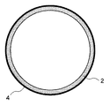
本発明のベルト状導電性部材の構成を図1に示す。本発明のベルト状導電性部材は、弾性体層2の外周面上に最表面層4が形成されて構成されている。また、弾性体層2と最表面層4の間に中間層が形成されていてもよい。
本発明のベルト状導電性部材の外周面の摩擦係数は、0.1以上0.3以下であることを必須とし、0.13以上0.27以下であることが好ましく、0.16以上0.24以下であることがより好ましい。本発明のベルト状導電性部材の外周面の摩擦係数が0.1未満であると、用紙の搬送力の低下またはベルト上に現像剤が保持できなくなるため画像不良が発生し、0.3を超えると、当接する感光体或いはクリーニングブレード等との摩擦が大きくなり、画像形成装置内において、駆動ロールを含む複数のロールで張架された場合に、ベルト伸長率の変化、及び駆動ロールとの間で発生するスリップの発生が無く、現像剤の転写均一性が向上するという効果が得られない。
The configuration of the belt-like conductive member of the present invention is shown in FIG. The belt-like conductive member of the present invention is configured by forming the outermost surface layer 4 on the outer peripheral surface of the
The friction coefficient of the outer peripheral surface of the belt-like conductive member of the present invention must be 0.1 or more and 0.3 or less, preferably 0.13 or more and 0.27 or less, and preferably 0.16 or more and 0 or less. More preferably, it is 24 or less. If the friction coefficient of the outer peripheral surface of the belt-like conductive member of the present invention is less than 0.1, the conveyance force of the paper is lowered or the developer cannot be held on the belt, and an image defect occurs. If exceeded, the friction with the abutting photoreceptor or cleaning blade increases, and in the image forming apparatus, when stretched by a plurality of rolls including the drive roll, the change in the belt extension rate and the drive roll No slip is generated between the two, and the effect of improving the transfer uniformity of the developer cannot be obtained.
また、本発明のベルト状導電性部材の内周面の摩擦係数は、0.4以上1.0以下であることを必須とし、0.45以上0.9以下であることが好ましく、0.5以上0.8以下であることがより好ましい。本発明のベルト状導電性部材の内周面の摩擦係数0.4未満であると、駆動ロールとの摩擦が小さくなり、画像形成装置内において、駆動ロールを含む複数のロールで張架された場合に、ベルト伸長率の変化、及び駆動ロールとの間で発生するスリップの発生が無く、現像剤の転写均一性が向上するという効果が得られず、1.0を超えると、紙粉および現像剤等が付着し易くなり、スリップを発生させる原因となる。 Further, the friction coefficient of the inner peripheral surface of the belt-like conductive member of the present invention must be 0.4 or more and 1.0 or less, preferably 0.45 or more and 0.9 or less. More preferably, it is 5 or more and 0.8 or less. When the friction coefficient of the inner peripheral surface of the belt-like conductive member of the present invention is less than 0.4, the friction with the drive roll is reduced, and the belt is stretched by a plurality of rolls including the drive roll in the image forming apparatus. In this case, there is no change in the belt elongation rate and the occurrence of slip between the driving roll and the effect of improving the transfer uniformity of the developer cannot be obtained. Developer or the like is likely to adhere, causing slip.
本発明のベルト状導電性部材の外周面の摩擦係数は、図2に示すように、平坦な金属板(材質:SUS304、表面粗さRa:0.1μm〜0.2μm)22をベルト状導電性部材20の内部に置き、摩擦係数測定機(HEIDON トライボギア ミューズ94iII)24をベルト状導電性部材20ベルト上に載せることにより測定した、ベルト状導電性部材20の外周面と摩擦係数測定機24の金属測定子26との摩擦係数である。
一方、本発明のベルト状導電性部材の内周面の摩擦係数は、図3に示すように、平坦な金属板(材質:SUS304、表面粗さRa:0.1μm〜0.2μm)22上にベルト状導電性部材20を置き、ベルト内部に摩擦係数測定機(HEIDON トライボギア ミューズ94iII)24を置くことにより測定した、ベルト状導電性部材20の内周面と摩擦係数測定機24の金属測定子26との摩擦係数である。
As shown in FIG. 2, the friction coefficient of the outer peripheral surface of the belt-shaped conductive member of the present invention is obtained by applying a flat metal plate (material: SUS304, surface roughness Ra: 0.1 μm to 0.2 μm) 22 to the belt-shaped conductive material. The outer peripheral surface of the belt-like
On the other hand, the friction coefficient of the inner peripheral surface of the belt-like conductive member of the present invention is as follows on a flat metal plate (material: SUS304, surface roughness Ra: 0.1 μm to 0.2 μm) 22, as shown in FIG. The belt-like
本発明のベルト状導電性部材の体積抵抗率は、25℃における体積抵抗率であり、1.0×10⁴〜1.0×10¹²Ω・cmであることが好ましく、さらに、中間転写ベルトとして用いる場合は、1.0×10⁷〜1.0×10¹¹Ω・cmであることが好ましく、転写搬送ベルトとして用いる場合は5.0×10⁴〜1.0×10¹⁰Ω・cmであることが好ましい。
尚、本発明のベルト状導電性部材の体積抵抗率は、25℃の条件下で、電極(アドバンテスト社製、R12702A/Bレジスティビィティ・チェンバ)をベルト内部に挿入し、ベルト外周面に電極と同軸上にリング状のアース電極を更に取り付け、電極およびリング状のアース電極に高抵抗測定器(アドバンテスト社製、R8340Aデジタル高抵抗/微小電流計)を接続し、印加電圧1000Vを印加し、10秒充電後の抵抗値を求めた。
The volume resistivity of the belt-like conductive member of the present invention is a volume resistivity at 25 ° C., preferably 1.0 × 10 4 to 1.0 × 10 12 Ω · cm, and further, an intermediate transfer belt. Is preferably 1.0 × 10 7 to 1.0 × 10 11 Ω · cm, and 5.0 × 10 4 to 1.0 × 10 10 Ω · cm when used as a transfer conveyance belt. It is preferable that
The volume resistivity of the belt-like conductive member of the present invention is 25 ° C. The electrode (advantest R12702A / B resilience chamber) is inserted into the belt and the belt outer peripheral surface is placed. A ring-shaped earth electrode is further mounted on the same axis as the electrode, and a high resistance measuring instrument (manufactured by Advantest, R8340A digital high resistance / microammeter) is connected to the electrode and the ring-shaped ground electrode, and an applied voltage of 1000 V is applied. The resistance value after charging for 10 seconds was obtained.
弾性体層2は、ゴム弾性体からなることが好ましい。前記ゴム弾性体の材料は、ジエン系もしくは非ジエン系のゴム弾性体であり、固形状、液状のどちらでもよく、アクリルゴム、イソプレンゴム、ブタジエンゴム、エチレン−プロピレン共重合ゴム、アクリロニトリル−ブタジエンゴム、スチレン−ブタジエンゴム、エピクロルヒドリン共重合ゴム、ウレタンゴム、シリコーンゴム、ブチルゴム、クロロプレンゴム、ノルボルネン等が挙げられ、中でもエチレン−プロピレン共重合ゴム、アクリロニトリル−ブタジエンゴム、スチレン−ブタジエンゴム、エピクロルヒドリン共重合ゴム、クロロプレンゴムが好ましい。これら弾性体は、単独または2種類以上を混合して用いることができる。
The
前記ゴム弾性体の体積抵抗率はカーボンブラック等の導電剤により調整することができる。更に必要に応じて軟化剤、可塑剤、硬化剤、加硫剤、加硫促進剤、老化防止剤、シリカおよび炭酸カルシウム等の充填剤等、通常ゴムに添加され得る材料を加えてもよい。 The volume resistivity of the rubber elastic body can be adjusted with a conductive agent such as carbon black. Furthermore, if necessary, materials that can be usually added to rubber, such as softeners, plasticizers, curing agents, vulcanizing agents, vulcanization accelerators, anti-aging agents, fillers such as silica and calcium carbonate, and the like may be added.
一方、最表面層4は、樹脂を含有していることが好ましく、最表面層4を構成する樹脂としては、ウレタン樹脂、ポリエステル、フェノール、アクリル、ポリウレタン、エポキシ樹脂、セルロース、共重合ナイロン等が挙げられ、ウレタン樹脂、ポリエステル、共重合ナイロンが好ましい。このうちの共重合ナイロンは、610ナイロン、11ナイロン、12ナイロンの内のいずれか1種または複数種を重合単位として含むものであって、この共重合体に含まれる他の重合単位としては、6ナイロン、66ナイロン等が挙げられる。ここで、610ナイロン、11ナイロン、12ナイロンよりなる重合単位が共重合体中に含まれる割合は、質量比で合わせて10%以上であるのが好ましい。前記重合単位が10%以上の場合は、調液性および表面層塗布時における成膜性に優れるとともに、特に繰り返し使用時における樹脂層の磨耗や樹脂層への異物付着が少なく、ベルトの耐久性が優れ、また同時に吸湿性が低く、環境による特性の変化も少なくなる。 On the other hand, the outermost surface layer 4 preferably contains a resin, and examples of the resin constituting the outermost surface layer 4 include urethane resin, polyester, phenol, acrylic, polyurethane, epoxy resin, cellulose, copolymer nylon, and the like. And urethane resin, polyester, and copolymer nylon are preferable. Among these, the copolymer nylon includes one or more of 610 nylon, 11 nylon, and 12 nylon as polymerized units, and the other polymerized units contained in the copolymer include: Examples include 6 nylon and 66 nylon. Here, it is preferable that the proportion of polymer units composed of 610 nylon, 11 nylon, and 12 nylon contained in the copolymer is 10% or more in total by mass ratio. When the polymerized unit is 10% or more, it is excellent in liquid preparation and film-forming properties at the time of coating the surface layer, and in particular, wear of the resin layer during repeated use and adhesion of foreign matter to the resin layer are small, and the durability of the belt In addition, the hygroscopicity is low, and the change in properties due to the environment is reduced.
最表面層4は、粒子状導電剤を含有していてもよい。粒子状導電剤は該導電性材料として、粒径が3μm以下で体積抵抗率が109Ωcm以下であるものが好ましい。例えば、酸化錫、酸化チタン、酸化亜鉛、CeO2、ZrO2、In2O3等の金属酸化物あるいはそれらの合金からなる微粒子、あるいはBaSO4やTiO2のような微粒子の表面にこれらの金属酸化物を被覆したもの、あるいはカーボンブラック等を用いることができる。
所望のベルトの体積抵抗値を得るために最表面層4の体積抵抗値は109Ω・cm以上が好ましく、前記粒子状導電剤添加量は、添加する導電性粒子によって異なるが、上述の最表面層4を構成する樹脂として記載の樹脂ならば、添加量は樹脂固形分に対し0%〜150%とすることが好ましい。
更に、最表面層4には、フッ素系あるいはシリコーン系の樹脂或いは微粒子を添加してもよく、その場合、表面が疎水性となってベルト表面への異物の付着が防止されるように作用する。また下の層との接着性向上のためにカップリング剤を添加することも可能である。
The outermost surface layer 4 may contain a particulate conductive agent. The particulate conductive agent is preferably a conductive material having a particle size of 3 μm or less and a volume resistivity of 10 9 Ωcm or less. For example, fine particles made of metal oxides such as tin oxide, titanium oxide, zinc oxide, CeO 2 , ZrO 2 , In 2 O 3 or alloys thereof, or these metals on the surface of fine particles such as BaSO 4 or TiO 2. An oxide-coated one or carbon black can be used.
In order to obtain the desired volume resistance value of the belt, the volume resistance value of the outermost surface layer 4 is preferably 10 9 Ω · cm or more, and the amount of the particulate conductive agent added varies depending on the conductive particles to be added, but the above-mentioned maximum If it is resin described as resin which comprises the surface layer 4, it is preferable to make addition amount into 0%-150% with respect to resin solid content.
Further, a fluorine-based or silicone-based resin or fine particles may be added to the outermost surface layer 4, and in this case, the surface becomes hydrophobic and acts to prevent the adhesion of foreign matters to the belt surface. . It is also possible to add a coupling agent in order to improve the adhesion with the lower layer.
また、本発明のベルト状導電性部材は、弾性体層2と最表面層4の間に中間層が形成されていてもよい。該中間層としては、抵抗調整、或いは下地として設けるもので、前記ゴム弾性体材料および前記最表面層を構成する樹脂に使用できる材料が好ましく、さらにゴムとしては、エチレン−プロピレン共重合ゴム、アクリロニトリル−ブタジエンゴム、スチレン−ブタジエンゴム、エピクロルヒドリン共重合ゴム、クロロプレンゴムが好ましく、樹脂としてはウレタン樹脂、ポリエステル、共重合ナイロン等が好ましい。
In the belt-like conductive member of the present invention, an intermediate layer may be formed between the
本発明のベルト状導電性部材は、25℃における硬度が65〜85であることが好ましく、70〜80であることがより好ましい。前記硬度が85を超えると、ベルトを伸長した際にベルト表面にクラックが発生する場合があり、65未満であると、ベルトが駆動する力に相反するようにベルトを静止する力が発生し、この静止する力が大きくなるとクリーニングブレード近傍でベルトの伸長率が変化したり、駆動ロールとの間でスリップが発生し画像欠陥を引き起こす場合がある。前記硬度は、例えば日本高分子計器社製アスカーMD−1硬度計を使用することにより測定できる。 The belt-like conductive member of the present invention preferably has a hardness at 25 ° C. of 65 to 85, and more preferably 70 to 80. If the hardness is greater than 85, cracks may occur on the belt surface when the belt is extended, and if it is less than 65, a force is generated to stop the belt against the driving force of the belt, If this static force increases, the belt elongation rate may change in the vicinity of the cleaning blade, or slip may occur with the drive roll, causing image defects. The hardness can be measured, for example, by using an Asker MD-1 hardness meter manufactured by Nippon Kobunshi Keiki Co., Ltd.
本発明のベルト状導電性部材の製造方法は、弾性体層の外周面上に少なくとも最表面層が形成されてなるベルト状導電性部材の製造方法であって、ベルト状の弾性体層を架橋する架橋工程と、該架橋工程後に弾性体層の内周面を研磨した後、弾性体層の外周面を研磨し、再度弾性体層の内周面を研磨する研磨工程と、研磨工程を経た弾性体層の外周面上に最表面層を形成する最表面層形成工程と、を有することを特徴とする。 The method for manufacturing a belt-shaped conductive member of the present invention is a method for manufacturing a belt-shaped conductive member in which at least the outermost surface layer is formed on the outer peripheral surface of the elastic layer, and the belt-shaped elastic layer is crosslinked. A polishing step, a polishing step of polishing the outer peripheral surface of the elastic layer after polishing the inner peripheral surface of the elastic layer after the cross-linking step, and a polishing step of polishing the inner peripheral surface of the elastic layer again And an outermost surface layer forming step of forming an outermost surface layer on the outer peripheral surface of the elastic body layer.
前記ベルト状の弾性体層は、ゴム弾性体等の材料および配合剤をバンバリーミキサー、ニーダー、2本ロール等の混練り機を使用し混練を行い、混合物を作製し、作製した混合物を押し出し機を使用してチューブ状に予備成型を行った後、円筒上の金型に被覆し、加硫した後、金型から取り外すことにより得られる。 The belt-like elastic body layer is prepared by kneading materials and compounding agents such as rubber elastic bodies using a kneader such as a Banbury mixer, a kneader, or a two-roll to produce a mixture, and extruding the produced mixture. It is obtained by pre-molding into a tube shape using, then coating on a cylindrical mold, vulcanizing, and then removing from the mold.
前記得られたベルト状の弾性体層は、蒸気加硫、プレス加硫、トランスファー加硫、熱空気加硫等の方法で架橋を行い円筒状の成形物を作製する(架橋工程)。
前記蒸気加硫は、加硫缶内に加圧水蒸気を充満させ、円筒状金型に被覆した弾性体層に熱および圧力をかけて加硫する方法である。
前記プレス加硫は、円筒状金型に被覆した弾性体層をプレス用金型に入れ、プレスにより挟み込み熱と圧力をかけて加硫する方法である。
前記熱空気加硫は、高温にされた室内に円筒状の金型に被覆した弾性体層を入れ、熱をかけて加硫する方法である。
The obtained belt-like elastic body layer is crosslinked by a method such as steam vulcanization, press vulcanization, transfer vulcanization, and hot air vulcanization to produce a cylindrical molded product (crosslinking step).
The steam vulcanization is a method in which pressurized steam is filled in a vulcanizing can and vulcanized by applying heat and pressure to an elastic body layer covered with a cylindrical mold.
The press vulcanization is a method in which an elastic body layer coated on a cylindrical mold is placed in a press mold and sandwiched by a press and vulcanized by applying heat and pressure.
The hot air vulcanization is a method in which an elastic body layer covered with a cylindrical mold is placed in a high temperature chamber and vulcanized by applying heat.
得られた円筒状の成形物は、研磨工程として、NC研磨機等で内周面を研磨(第一研磨工程)した後、弾性体層の外周面を研磨(第二研磨工程)し、再度弾性体層の内周面を研磨(第三研磨工程)する。
本発明のベルト状導電性部材を得るためには、円筒状の成形物の外周面を平滑にし、内周面を見かけ上の接触面積が増加するよう荒らすことが好ましい。しかし、内周面を荒らした後、外周面を研磨すると表面の平滑性が失われ早期に円筒状の成形物表面にクラックが発生してしまう。そこで本発明における研磨工程では、円筒状の成形物の内周面を研磨することにより平滑にした後、円筒状の成形物の外周面を研磨することにより平滑にし、再度円筒状の成形物の内周面を研磨することにより荒し、外周面の平滑性と内周面の粗面性を両立させている。これら第一〜第三研磨工程においては、砥石種類、ワーク回転数、砥石回転数、送り速度等の条件によって摩擦係数、表面平滑性を変化させることができる。以下に各研磨工程について説明する。
The obtained cylindrical molded product is polished as a polishing step with an NC grinder or the like (first polishing step), then the outer peripheral surface of the elastic layer is polished (second polishing step), and again The inner peripheral surface of the elastic layer is polished (third polishing step).
In order to obtain the belt-shaped conductive member of the present invention, it is preferable to smooth the outer peripheral surface of the cylindrical molded product and roughen the inner peripheral surface so that the apparent contact area increases. However, if the outer peripheral surface is polished after roughening the inner peripheral surface, the smoothness of the surface is lost, and cracks are generated on the surface of the cylindrical molded product at an early stage. Therefore, in the polishing step of the present invention, the inner peripheral surface of the cylindrical molded product is smoothed by polishing, and then the outer peripheral surface of the cylindrical molded product is smoothed by polishing, and again the cylindrical molded product It is roughened by polishing the inner peripheral surface, and both smoothness of the outer peripheral surface and rough surface properties of the inner peripheral surface are achieved. In these first to third polishing steps, the friction coefficient and surface smoothness can be changed according to conditions such as the type of grindstone, the number of revolutions of the workpiece, the number of revolutions of the grindstone, and the feed rate. Each polishing process will be described below.
上述のように、前記第一研磨工程は、円筒状の成形物の内周面を平滑にするための工程であり、これにより次の第二研磨工程で容易に円筒状の成形物の外周面を平滑にすることができる。前記第一研磨工程は、内周面の入射角85°のグロス値を、30〜40とすることが好ましく、33〜38とすることがより好ましい。 As described above, the first polishing step is a step for smoothing the inner peripheral surface of the cylindrical molded product, whereby the outer peripheral surface of the cylindrical molded product can be easily obtained in the next second polishing step. Can be smoothed. In the first polishing step, the gloss value at an incident angle of 85 ° on the inner peripheral surface is preferably 30 to 40, and more preferably 33 to 38.
上述のように、前記第二研磨工程は、円筒状の成形物の外周面を平滑にするための工程である。前記第二研磨工程は、外周面の入射角85°のグロス値を、30〜40とすることが好ましく、34〜39とすることがより好ましい。 As described above, the second polishing step is a step for smoothing the outer peripheral surface of the cylindrical molded product. In the second polishing step, the gloss value at an incident angle of 85 ° on the outer peripheral surface is preferably 30 to 40, and more preferably 34 to 39.
上述のように、前記第三研磨工程は、円筒状の成形物の内周面を荒らすための工程である。前記第二研磨工程は、内周面の入射角85°のグロス値を、4〜10とすることが好ましく、5〜9とすることがより好ましい。 As described above, the third polishing step is a step for roughening the inner peripheral surface of the cylindrical molded product. In the second polishing step, the gloss value at an incident angle of 85 ° on the inner peripheral surface is preferably 4 to 10, and more preferably 5 to 9.
前記最表面層形成工程は、ベルト状導電性部材の表面の平滑性を向上させるための工程である。最表面層の形成は、前記樹脂をスプレーコート、浸漬塗布等によって、最表面層の厚さが3〜10μmとなるようにコートすることで、目的とする外周面の摩擦係数を得ることができる。なお、スプレーコートの場合は、塗料の吐出量を調整することにより厚さを制御することができる。 The outermost surface layer forming step is a step for improving the smoothness of the surface of the belt-like conductive member. The outermost surface layer can be formed by coating the resin so that the thickness of the outermost surface layer is 3 to 10 μm by spray coating, dip coating, or the like, thereby obtaining the desired friction coefficient of the outer peripheral surface. . In the case of spray coating, the thickness can be controlled by adjusting the amount of paint discharged.
既述の本発明のベルト状導電性部材は、上述の本発明のベルト状導電性部材の製造方法により好ましく得られる。 The belt-like conductive member of the present invention described above is preferably obtained by the above-described method for producing a belt-shaped conductive member of the present invention.
本発明の画像形成装置は、少なくとも、感光体と、駆動ロールを含む複数のロールに張架されたベルト状導電性部材と、を備える画像形成装置であって、前記ベルト状導電性部材が既述の本発明のベルト状導電性部材であることを特徴とする。
本発明の画像形成装置の一例の要部を図4に示す。図4に示すように、本発明の画像形成装置の一例は、感光体30と、駆動ロール34及び従動ロール36に張架された転写搬送ベルト32と、を備えている。
An image forming apparatus of the present invention is an image forming apparatus comprising at least a photosensitive member and a belt-like conductive member stretched around a plurality of rolls including a drive roll, wherein the belt-like conductive member is already present. It is a belt-like conductive member of the present invention described above.
The principal part of an example of the image forming apparatus of the present invention is shown in FIG. As shown in FIG. 4, an example of the image forming apparatus of the present invention includes a
本発明の画像形成装置の一例では、転写搬送ベルト32上に記録用紙40を保持した後、感光体30上のトナー像を転写ロール38により、転写搬送ベルト32上の記録用紙40に転写し、更に記録用紙40を搬送することができる。
本発明の画像形成装置に用いる感光体は、特に制限されるものではなく、例えば、表面がメチロール基を有するフェノール誘導体からなるものが挙げられる。該メチロール基を有するフェノール誘導体は、モノメチロールフェノール類、ジメチロールフェノール類若しくはトリメチロールフェノール類のモノマー、それらの混合物、それらがオリゴマー化されたもの、又はそれらモノマーとオリゴマーの混合物が挙げられる。このようなメチロール基を有するフェノール誘導体は、レゾルシン、ビスフェノール等、フェノール、クレゾール、キシレノール、パラアルキルフェノール、パラフェニルフェノール等の水酸基を1個含む置換フェノール類、カテコール、レゾルシノール、ヒドロキノン等の水酸基を2個含む置換フェノール類、ビスフェノールA、ビスフェノールZ等のビスフェノール類、ビフェノール類等、フェノール構造を有する化合物と、ホルムアルデヒド、パラホルムアルデヒド等とを、酸触媒又はアルカリ触媒下で反応させることで得られるもので、一般にフェノール樹脂として市販されているものも使用できる。
In an example of the image forming apparatus of the present invention, after holding the
The photoreceptor used in the image forming apparatus of the present invention is not particularly limited, and examples thereof include those composed of a phenol derivative having a methylol group on the surface. Examples of the phenol derivative having a methylol group include monomers of monomethylolphenols, dimethylolphenols or trimethylolphenols, mixtures thereof, oligomers thereof, or mixtures of these monomers and oligomers. Such phenol derivatives having a methylol group include resorcin, bisphenol, etc., substituted phenols containing one hydroxyl group such as phenol, cresol, xylenol, paraalkylphenol, paraphenylphenol, and two hydroxyl groups such as catechol, resorcinol, hydroquinone, etc. It is obtained by reacting a compound having a phenol structure, such as substituted phenols, bisphenol A, bisphenol Z, and the like having a phenol structure with formaldehyde, paraformaldehyde, etc. in the presence of an acid catalyst or an alkali catalyst, Generally what is marketed as a phenol resin can also be used.
本発明の画像形成装置は、転写搬送ベルト32として本発明のベルト状導電性部材を用いることにより、画像形成装置内において、駆動ロールを含む複数のロールで張架された場合に、ベルト伸長率の変化、及び駆動ロールとの間で発生するスリップの発生が無く、現像剤の転写均一性を向上させることができる。
また、本発明の画像形成装置は、図4に示すように記録用紙40を搬送した後、転写搬送ベルト32をクリーニングするクリーニングブレード50を備えることが好ましい。本発明のベルト状導電性部材である転写搬送ベルト32は、外周面及び内周面の摩擦係数が制御されているため、転写搬送ベルト32にクリーニングブレード50を押し当ててクリーニングしても、ベルト伸長率の変化、及び駆動ロールとの間で発生するスリップの発生が無く、好ましくクリーニングすることができる。
The image forming apparatus of the present invention uses the belt-like conductive member of the present invention as the
The image forming apparatus of the present invention preferably includes a cleaning blade 50 for cleaning the transfer / conveying
本発明の画像形成装置に用いられるクリーニングブレード50としては、保持部材52に取り付けて使用される、ブレード状のゴムからなる構成のクリーニングブレードが挙げられ、前記ブレード状のゴムは単層でも複層であってもよい。また、クリーニングブレード50は、クリーニング対象部材(例えば本発明のベルト状導電性部材)に当接する部分のみが、クリーニングブレード50を構成する他の部分と異なる硬度を有していてもよく、複層の場合はクリーニング対称部材に当接する側の層のみが他の層と異なる硬度を有していてもよい。クリーニングブレード50として使用するゴムは、前述の弾性体層に使用するゴムが好ましく、中でもウレタンゴムが好ましい。
Examples of the cleaning blade 50 used in the image forming apparatus of the present invention include a cleaning blade made of blade-like rubber that is used by being attached to a holding
本発明の画像形成装置に用いられる転写ロール38としては、金属芯体上に弾性層を有する構成であることが好ましく、この弾性層は、前述の弾性体層に使用するゴムの発泡体からなることが好ましく、中でもエチレン−プロピレン共重合ゴム、アクリロニトリル−ブタジエンゴム、スチレン−ブタジエンゴム、エピクロルヒドリン共重合ゴム、クロロプレンゴムを単独もしくは2種以上混合させた発泡体が好ましい。
The
本発明の画像形成装置に用いられる駆動ロール34としては、金属を使用したものを使用することが好ましい。
As the driving
本発明の画像形成装置は、帯電装置42、露光装置44、現像装置46、感光体30をクリーニングするクリーニング部材48等の構成については、従来の電子写真方式の画像形成装置のものを用いることができる。
In the image forming apparatus of the present invention, the structure of the charging
以上、本発明のベルト状導電性部材を転写搬送ベルトに用いた場合を説明したが、本発明のベルト状導電性部材を中間転写ベルトに用いても同様の効果が得られる。 As described above, the case where the belt-like conductive member of the present invention is used for the transfer conveyance belt has been described, but the same effect can be obtained even if the belt-shaped conductive member of the present invention is used for the intermediate transfer belt.
以下、本発明を実施例により、具体的に説明するが、本発明は以下の実施例に限定されるものではない。
<実施例1>
クロロプレン(電気化学工業社製 ES−40)100質量部に、アサヒサーマル(旭カーボン社製)40質量部、ケッチェンブラックEC 8質量部、酸化マグネシウム(協和化学工業社製 キョーワマグ150)4質量部、硫黄0.5質量部(鶴見化学工業社製 200メッシュ)、加硫促進剤2.0質量部(大内新興化学工業社製 ノクセラーTS:1.0質量部、ノクセラーDT:1.0質量部)を加え、オープンロールで混練りした混合物を直径95mmの金属製パイプに厚さ1.0mmの円筒状に被覆し、加硫缶に入れ170℃で30分加硫させ、金属性のパイプから抜きとり円筒状の成型物を得た。得られた円筒状の成型物の内周面をNC研磨機(水口製作所製)により研磨し、内周面の入射角85°のグロス値を33.8とした。次に円筒状の成型物の外周面をNC研磨機(水口製作所製)により研磨し、外周面の入射角85°のグロス値を36.4とした。更にその後、円筒状の成型物の内周面をNC研磨機(水口製作所製)により研磨し、内周面の入射角85°のグロス値を8.7として、厚さ0.47mmの円筒状の成型物を得た。
EXAMPLES Hereinafter, although an Example demonstrates this invention concretely, this invention is not limited to a following example.
<Example 1>
100 parts by mass of chloroprene (ES-40 manufactured by Denki Kagaku Kogyo Co., Ltd.), 40 parts by mass of Asahi Thermal (manufactured by Asahi Carbon Co., Ltd.), 8 parts by mass of Ketjen Black EC, 4 parts by mass of magnesium oxide (Kyowa Mag 150 manufactured by Kyowa Chemical Industry Co., Ltd.) , 0.5 parts by mass of sulfur (200 mesh manufactured by Tsurumi Chemical Co., Ltd.), 2.0 parts by mass of a vulcanization accelerator (manufactured by Ouchi Shinsei Chemical Co., Ltd. Noxeller TS: 1.0 part by mass, Noxeller DT: 1.0 mass Part) and a mixture kneaded with an open roll is coated on a metal pipe with a diameter of 95 mm in a cylindrical shape with a thickness of 1.0 mm, placed in a vulcanizing can and vulcanized at 170 ° C. for 30 minutes, and then a metallic pipe A cylindrical shaped product was obtained by extracting from the product. The inner peripheral surface of the obtained cylindrical molded product was polished by an NC polishing machine (manufactured by Mizuguchi Seisakusho), and the gloss value at an incident angle of 85 ° on the inner peripheral surface was set to 33.8. Next, the outer peripheral surface of the cylindrical molded product was polished by an NC polishing machine (manufactured by Mizuguchi Seisakusho), and the gloss value at an incident angle of 85 ° on the outer peripheral surface was set to 36.4. After that, the inner peripheral surface of the cylindrical molded product is polished by an NC polishing machine (manufactured by Mizuguchi Seisakusho), and the gross value at an incident angle of 85 ° on the inner peripheral surface is 8.7, and the cylindrical shape has a thickness of 0.47 mm. The molded product was obtained.
上述のように研磨した円筒状の成型物の外周面に、最表面層形成用のJLY−601ESD(日本アチソン社製)塗布液をスプレーコートにてコーティングを行い、140℃で30分間焼成し、最表面層を形成し、ベルト状導電性部材を得た。このときの最表面層の厚みは5.0μmであった。既述の方法で測定したベルト状導電性部材の外周面の摩擦係数は0.21、内周面の摩擦係数は0.65であった。また、ベルト状導電性部材の25℃における硬度をアスカーMD−1型硬度計を用いて測定した。その結果77であった。更に既述の方法で測定した25℃における体積抵抗率は8.0×10⁶Ω・cmであった。 The outer peripheral surface of the cylindrical molded product polished as described above is coated with a coating solution of JLY-601 ESD (manufactured by Nippon Atsson Co., Ltd.) for forming the outermost surface layer by spray coating, and baked at 140 ° C. for 30 minutes. An outermost surface layer was formed to obtain a belt-like conductive member. The thickness of the outermost surface layer at this time was 5.0 μm. The friction coefficient of the outer peripheral surface of the belt-like conductive member measured by the method described above was 0.21, and the friction coefficient of the inner peripheral surface was 0.65. Further, the hardness of the belt-like conductive member at 25 ° C. was measured using an Asker MD-1 type hardness meter. As a result, it was 77. Furthermore, the volume resistivity at 25 ° C. measured by the method described above was 8.0 × 10 6 Ω · cm.
このようにして作製されたベルト状導電性部材をDocuCentre a1100(富士ゼロックス社製)の転写搬送ベルトに装着し、温度22℃、湿度55%の環境下で、プロセススピード461mm/secの条件で72時間ランニングテストした後、同じく温度22℃、湿度55%の環境下で、記録用紙としてA4サイズのJ紙(富士ゼロックスオフィスサプライ社製)を用い、印字テストを実施した。初期及び10000枚プリント後の画質、及び転写搬送ベルトの表面の汚れを評価した。更に用紙搬送性を評価した。その結果を表1に示す。尚、DocuCentre a1100は、感光体及び転写搬送ベルトをクリーニングするクリーニングブレードを備えたものであり、転写搬送ベルトは、駆動ロールを含む複数のロールに張架された状態で設置した。 The belt-like conductive member thus produced is attached to a transfer conveyance belt of DocuCentre a1100 (manufactured by Fuji Xerox Co., Ltd.). After a time running test, a printing test was conducted using A4 size J paper (manufactured by Fuji Xerox Office Supply) as recording paper under the same temperature of 22 ° C. and humidity of 55%. The initial image quality after printing 10,000 sheets, and the stain on the surface of the transfer conveyance belt were evaluated. Furthermore, the paper transportability was evaluated. The results are shown in Table 1. The DocuCentre a1100 is provided with a cleaning blade for cleaning the photosensitive member and the transfer conveyance belt, and the transfer conveyance belt is installed in a stretched state on a plurality of rolls including a drive roll.
<実施例2>
クロロプレン(電気化学工業社製 ES−40)70質量部に、エチレンプロピレン共重合体(JSR社製 EP−33)30質量部、アサヒサーマル(旭カーボン社製)40質量部、ケッチェンブラックEC8質量部、酸化マグネシウム(協和化学工業社製 キョーワマグ150)4質量部、硫黄(鶴見化学工業社製 200メッシュ)0.5質量部、加硫促進剤2.0質量部(大内新興化学工業社製 ノクセラーTS:1.0質量部、ノクセラーDT:1.0質量部)を加え、オープンロールで混練りした混合物を直径95mmの金属製パイプに厚さ1.0mmの円筒状に被覆し加硫缶に入れ170℃で30分加硫させ、金属性のパイプから抜きとり円筒状の成型物を得た。得られた円筒状の成型物の内周面をNC研磨機(水口製作所製)により研磨し、内周面の入射角85°のグロス値を34.7とした。次に円筒状の成型物の外周面をNC研磨機(水口製作所製)により研磨し、外周面の入射角85°のグロス値を34.1とした。更にその後、円筒状の成型物の内周面をNC研磨機(水口製作所製)により研磨し、内周面の入射角85°のグロス値を8.4として、厚さ0.47mmの円筒状の成型物を得た。
<Example 2>
70 parts by mass of chloroprene (ES-40 manufactured by Denki Kagaku Kogyo Co., Ltd.), 30 parts by mass of an ethylene propylene copolymer (EP-33 manufactured by JSR), 40 parts by mass of Asahi Thermal (manufactured by Asahi Carbon Co., Ltd.), 8 masses of ketjen black EC Part, magnesium oxide (Kyowa Chemical Industry Co., Ltd. Kyowa Mag 150) 4 parts by mass, sulfur (Tsurumi Chemical Co., Ltd. 200 mesh) 0.5 parts by mass, vulcanization accelerator 2.0 parts by mass (Ouchi Shinsei Chemical Industry Co., Ltd.) Noxeller TS: 1.0 part by mass, Noxeller DT: 1.0 part by mass), and the mixture kneaded with an open roll is coated on a metal pipe with a diameter of 95 mm in a cylindrical shape with a thickness of 1.0 mm, and a vulcanized can It was vulcanized at 170 ° C. for 30 minutes and extracted from a metallic pipe to obtain a cylindrical molded product. The inner peripheral surface of the obtained cylindrical molded product was polished by an NC polishing machine (manufactured by Mizuguchi Seisakusho), and the gloss value at an incident angle of 85 ° on the inner peripheral surface was set to 34.7. Next, the outer peripheral surface of the cylindrical molded product was polished by an NC polishing machine (manufactured by Mizuguchi Seisakusho), and the gloss value at an incident angle of 85 ° on the outer peripheral surface was set to 34.1. Thereafter, the inner peripheral surface of the cylindrical molded product is polished by an NC polishing machine (manufactured by Mizuguchi Seisakusho), and the gross value at an incident angle of 85 ° on the inner peripheral surface is set to 8.4, and the cylindrical shape has a thickness of 0.47 mm. The molded product was obtained.
上述のように研磨した円筒状の成型物の外周面に、最表面層形成用のJLY−601ESD(日本アチソン社製)塗布液をスプレーコートにてコーティングを行い、140℃で30分間焼成し、最表面層を形成し、ベルト状導電性部材を得た。このときの最表面層の厚みは5.0μmであった。実施例1と同様にして測定した得られたベルト状導電性部材の外周面の摩擦係数は0.19、内周面の摩擦係数は0.50であった。また、実施例1と同様にしてベルト状導電性部材の硬度を測定した。その結果78であった。更に実施例1と同様にして測定した25℃における体積抵抗率は7.4×10⁵Ω・cmであった。
このようにして作製されたベルト状導電性部材を実施例1と同様にして、初期及び10000枚プリント後の画質、及び転写搬送ベルトの表面の汚れ、用紙搬送性を評価した。その結果を表1に示す。
The outer peripheral surface of the cylindrical molded product polished as described above is coated with a coating solution of JLY-601 ESD (manufactured by Nippon Atsson Co., Ltd.) for forming the outermost surface layer by spray coating, and baked at 140 ° C. for 30 minutes. An outermost surface layer was formed to obtain a belt-like conductive member. The thickness of the outermost surface layer at this time was 5.0 μm. The friction coefficient of the outer peripheral surface of the obtained belt-like conductive member measured in the same manner as in Example 1 was 0.19, and the friction coefficient of the inner peripheral surface was 0.50. Further, the hardness of the belt-like conductive member was measured in the same manner as in Example 1. As a result, it was 78. Furthermore, the volume resistivity at 25 ° C. measured in the same manner as in Example 1 was 7.4 × 10 5 Ω · cm.
The belt-like conductive member thus produced was evaluated in the same manner as in Example 1 for the initial image quality after printing 10,000 sheets, the contamination on the surface of the transfer conveyance belt, and the sheet conveyance property. The results are shown in Table 1.
<実施例3>
クロロプレン(電気化学工業社製 ES−40)70質量部に、エピクロルヒドリン共重合体(日本ゼオン社製 ゼクロン3106)30質量部にアサヒサーマル(旭カーボン社製)40質量部、ケッチェンブラックEC8質量部、酸化マグネシウム(協和化学工業社製 キョーワマグ150)4質量部、硫黄(鶴見化学工業社製 200メッシュ)0.5質量部、加硫促進剤2.0質量部(大内新興化学工業社製 ノクセラーTS:1.0質量部、ノクセラーDT:1.0質量部)を加え、オープンロールで混練りした混合物を直径95mmの金属製パイプに厚さ1.0mmの円筒状に被覆し加硫缶に入れ170℃で30分加硫させ、金属性のパイプから抜きとり円筒状の成型物を得た。得られた円筒状の成型物の内周面をNC研磨機(水口製作所製)により研磨し、内周面の入射角85°のグロス値を33.4とした。次に円筒状の成型物の外周面をNC研磨機(水口製作所製)により研磨し、外周面の入射角85°のグロス値を36.2とした。更にその後、円筒状の成型物の内周面をNC研磨機(水口製作所製)により研磨し、内周面の入射角85°のグロス値を6.2として、厚さ0.47mmの円筒状の成型物を得た。
<Example 3>
70 parts by mass of chloroprene (ES-40 manufactured by Denki Kagaku Kogyo Co., Ltd.), 30 parts by mass of epichlorohydrin copolymer (Zeklon 3106 manufactured by Nippon Zeon Co., Ltd.), 40 parts by mass of Asahi Thermal (Asahi Carbon Co., Ltd.), 8 parts by mass of Ketjen Black EC , Magnesium oxide (Kyowa Chemical Industry Kyowa Mag 150) 4 parts by mass, Sulfur (Tsurumi Chemical Co., Ltd. 200 mesh) 0.5 parts by mass, Vulcanization accelerator 2.0 parts by mass (Ouchi Shinsei Chemical Co., Ltd. Noxeller) TS: 1.0 part by mass, NOXELLER DT: 1.0 part by mass), and the mixture kneaded with an open roll is coated on a metal pipe having a diameter of 95 mm in a cylindrical shape with a thickness of 1.0 mm, and then vulcanized. The mixture was vulcanized at 170 ° C. for 30 minutes and extracted from a metallic pipe to obtain a cylindrical molded product. The inner peripheral surface of the obtained cylindrical molded product was polished by an NC polishing machine (manufactured by Mizuguchi Seisakusho), and the gloss value at an incident angle of 85 ° on the inner peripheral surface was set to 33.4. Next, the outer peripheral surface of the cylindrical molded product was polished by an NC polishing machine (manufactured by Mizuguchi Seisakusho), and the gloss value at an incident angle of 85 ° on the outer peripheral surface was set to 36.2. Thereafter, the inner peripheral surface of the cylindrical molded product is polished by an NC polishing machine (manufactured by Mizuguchi Seisakusho), and the gross value at an incident angle of 85 ° on the inner peripheral surface is 6.2, and the cylindrical shape has a thickness of 0.47 mm. The molded product was obtained.
上述のように研磨した円筒状の成型物の外周面に、最表面層形成用のJLY−601ESD(日本アチソン社製)塗布液をスプレーコートにてコーティングを行い、140℃で30分間焼成し、最表面層を形成し、ベルト状導電性部材を得た。このときの最表面層の厚みは5.0μmであった。実施例1と同様にして測定した得られたベルト状導電性部材の外周面の摩擦係数は0.21、内周面の摩擦係数は0.58であった。また、実施例1と同様にしてベルト状導電性部材の硬度を測定した。その結果77であった。更に実施例1と同様にして測定した25℃における体積抵抗率は6.3×10⁶Ω・cmであった。
このようにして作製されたベルト状導電性部材を実施例1と同様にして、初期及び10000枚プリント後の画質、及び転写搬送ベルトの表面の汚れ、用紙搬送性を評価した。その結果を表1に示す。
The outer peripheral surface of the cylindrical molded product polished as described above is coated with a coating solution of JLY-601 ESD (manufactured by Nippon Atsson Co., Ltd.) for forming the outermost surface layer by spray coating, and baked at 140 ° C. for 30 minutes. An outermost surface layer was formed to obtain a belt-like conductive member. The thickness of the outermost surface layer at this time was 5.0 μm. The friction coefficient of the outer peripheral surface of the obtained belt-like conductive member measured in the same manner as in Example 1 was 0.21, and the friction coefficient of the inner peripheral surface was 0.58. Further, the hardness of the belt-like conductive member was measured in the same manner as in Example 1. As a result, it was 77. Furthermore, the volume resistivity at 25 ° C. measured in the same manner as in Example 1 was 6.3 × 10 6 Ω · cm.
The belt-like conductive member thus produced was evaluated in the same manner as in Example 1 for the initial image quality after printing 10,000 sheets, the contamination on the surface of the transfer conveyance belt, and the sheet conveyance property. The results are shown in Table 1.
<実施例4>
クロロプレン(電気化学工業社製 ES−40)70質量部に、エピクロルヒドリン共重合体(日本ゼオン社製 ゼクロン3106)30質量部にアサヒサーマル(旭カーボン社製)40質量部、ケッチェンブラックEC8質量部、酸化マグネシウム(協和化学工業社製 キョーワマグ150)4質量部、硫黄(鶴見化学工業社製 200メッシュ)0.5質量部、加硫促進剤2.0質量部(大内新興化学工業社製 ノクセラーTS:1.0質量部、ノクセラーDT:1.0質量部)を加え、オープンロールで混練りした混合物を直径95mmの金属製パイプに厚さ1.0mmの円筒状に被覆し加硫缶に入れ170℃で30分加硫させ、金属性のパイプから抜きとり円筒状の成型物を得た。得られた円筒状の成型物の内周面をNC研磨機(水口製作所製)により研磨し、内周面の入射角85°のグロス値を37.9とした。次に円筒状の成型物の外周面をNC研磨機(水口製作所製)により研磨し、外周面の入射角85°のグロス値を38.1とした。更にその後、円筒状の成型物の内周面をNC研磨機(水口製作所製)により研磨し、内周面の入射角85°のグロス値を5.7として、厚さ0.47mmの円筒状の成型物を得た。
<Example 4>
70 parts by mass of chloroprene (ES-40 manufactured by Denki Kagaku Kogyo Co., Ltd.), 30 parts by mass of epichlorohydrin copolymer (Zeklon 3106 manufactured by Nippon Zeon Co., Ltd.), 40 parts by mass of Asahi Thermal (Asahi Carbon Co., Ltd.), 8 parts by mass of Ketjen Black EC , Magnesium oxide (Kyowa Chemical Industry Kyowa Mag 150) 4 parts by mass, Sulfur (Tsurumi Chemical Co., Ltd. 200 mesh) 0.5 parts by mass, Vulcanization accelerator 2.0 parts by mass (Ouchi Shinsei Chemical Co., Ltd. Noxeller) TS: 1.0 part by mass, NOXELLER DT: 1.0 part by mass), and the mixture kneaded with an open roll is coated on a metal pipe having a diameter of 95 mm in a cylindrical shape with a thickness of 1.0 mm, and then vulcanized. The mixture was vulcanized at 170 ° C. for 30 minutes and extracted from a metallic pipe to obtain a cylindrical molded product. The inner peripheral surface of the obtained cylindrical molded product was polished by an NC polishing machine (manufactured by Mizuguchi Seisakusho), and the gloss value at an incident angle of 85 ° of the inner peripheral surface was set to 37.9. Next, the outer peripheral surface of the cylindrical molded product was polished by an NC polishing machine (manufactured by Mizuguchi Seisakusho), and the gloss value at an incident angle of 85 ° on the outer peripheral surface was set to 38.1. After that, the inner peripheral surface of the cylindrical molded product is polished by an NC polishing machine (manufactured by Mizuguchi Seisakusho), and the gross value at an incident angle of 85 ° on the inner peripheral surface is set to 5.7, and the cylindrical shape has a thickness of 0.47 mm. The molded product was obtained.
上述のように研磨した円筒状の成型物の外周面に、最表面層形成用のJLY−601ESD(日本アチソン社製)塗布液をスプレーコートにてコーティングを行い、140℃で30分間焼成し、最表面層を形成し、ベルト状導電性部材を得た。このときの最表面層の厚みは5.0μmであった。実施例1と同様にして測定した得られたベルト状導電性部材の外周面の摩擦係数は0.23、内周面の摩擦係数は0.46であった。また、実施例1と同様にしてベルト状導電性部材の硬度を測定した。その結果77であった。更に実施例1と同様にして測定した25℃における体積抵抗率は5.2×10⁶Ω・cmであった。
このようにして作製されたベルト状導電性部材を実施例1と同様にして、初期及び10000枚プリント後の画質、及び転写搬送ベルトの表面の汚れ、用紙搬送性を評価した。その結果を表1に示す。
The outer peripheral surface of the cylindrical molded product polished as described above is coated with a coating solution of JLY-601 ESD (manufactured by Nippon Atsson Co., Ltd.) for forming the outermost surface layer by spray coating, and baked at 140 ° C. for 30 minutes. An outermost surface layer was formed to obtain a belt-like conductive member. The thickness of the outermost surface layer at this time was 5.0 μm. The friction coefficient of the outer peripheral surface of the obtained belt-like conductive member measured in the same manner as in Example 1 was 0.23, and the friction coefficient of the inner peripheral surface was 0.46. Further, the hardness of the belt-like conductive member was measured in the same manner as in Example 1. As a result, it was 77. Furthermore, the volume resistivity at 25 ° C. measured in the same manner as in Example 1 was 5.2 × 10 6 Ω · cm.
The belt-like conductive member thus produced was evaluated in the same manner as in Example 1 for the initial image quality after printing 10,000 sheets, the contamination on the surface of the transfer conveyance belt, and the sheet conveyance property. The results are shown in Table 1.
<比較例1>
クロロプレン(電気化学工業社製 ES−40)100質量部に、アサヒサーマル(旭カーボン社製)40質量部、ケッチェンブラックEC8質量部、酸化マグネシウム(協和化学工業社製 キョーワマグ150)4質量部、硫黄(鶴見化学工業社製 200メッシュ)0.5質量部、加硫促進剤2.0質量部(大内新興化学工業社製 ノクセラーTS:1.0質量部、ノクセラーDT:1.0質量部)を加え、オープンロールで混練りした混合物を直径95mmの金属製パイプに厚さ1.0mmの円筒状に被覆し加硫缶に入れ170℃で30分加硫させ、金属性のパイプから抜きとり円筒状の成型物を得た。得られた円筒状の成型物の内周面をNC研磨機(水口製作所製)により研磨し、内周面の入射角85°のグロス値を36.9とした。次に円筒状の成型物の外周面をNC研磨機(水口製作所製)により研磨し、外周面の入射角85°のグロス値を33.5として、厚さ0.47mmの円筒状の成型物を得た。
<Comparative Example 1>
100 parts by mass of chloroprene (ES-40 manufactured by Denki Kagaku Kogyo Co., Ltd.), 40 parts by mass of Asahi Thermal (manufactured by Asahi Carbon Co., Ltd.), 8 parts by mass of Ketjen Black EC, 4 parts by mass of magnesium oxide (Kyowa Mag 150 manufactured by Kyowa Chemical Industry Co., Ltd.) 0.5 parts by mass of sulfur (200 mesh manufactured by Tsurumi Chemical Industry Co., Ltd.), 2.0 parts by mass of vulcanization accelerator (manufactured by Ouchi Shinsei Chemical Co., Ltd. Noxeller TS: 1.0 part by mass, Noxeller DT: 1.0 part by mass) ), And the mixture kneaded with an open roll is coated on a metal pipe with a diameter of 95 mm in a cylindrical shape with a thickness of 1.0 mm, placed in a vulcanizing can and vulcanized at 170 ° C. for 30 minutes, and then extracted from the metal pipe A cylindrical molded product was obtained. The inner peripheral surface of the obtained cylindrical molded product was polished by an NC polishing machine (manufactured by Mizuguchi Seisakusho), and the gloss value at an incident angle of 85 ° on the inner peripheral surface was set to 36.9. Next, the outer peripheral surface of the cylindrical molded product is polished by an NC polishing machine (manufactured by Mizuguchi Seisakusho), the gloss value at an incident angle of 85 ° on the outer peripheral surface is 33.5, and the cylindrical molded product is 0.47 mm thick. Got.
上述のように研磨した円筒状の成型物の外周面に、最表面層形成用のJLY−601ESD(日本アチソン社製)塗布液をスプレーコートにてコーティングを行い、140℃で30分間焼成し、最表面層を形成し、ベルト状導電性部材を得た。このときの最表面層の厚みは5.0μmであった。実施例1と同様にして測定した得られたベルト状導電性部材の外周面の摩擦係数は0.22、裏面の摩擦係数は0.21であった。また、実施例1と同様にしてベルト状導電性部材の硬度を測定した。その結果77であった。更に実施例1と同様にして測定した25℃における体積抵抗率は5.7×10⁶Ω・cmであった。
このようにして作製されたベルト状導電性部材を実施例1と同様にして、初期及び10000枚プリント後の画質、及び転写搬送ベルトの表面の汚れ、用紙搬送性を評価した。その結果を表1に示す。
The outer peripheral surface of the cylindrical molded product polished as described above is coated with a coating solution of JLY-601 ESD (manufactured by Nippon Atsson Co., Ltd.) for forming the outermost surface layer by spray coating, and baked at 140 ° C. for 30 minutes. An outermost surface layer was formed to obtain a belt-like conductive member. The thickness of the outermost surface layer at this time was 5.0 μm. The friction coefficient of the outer peripheral surface of the obtained belt-like conductive member measured in the same manner as in Example 1 was 0.22, and the friction coefficient of the back surface was 0.21. Further, the hardness of the belt-like conductive member was measured in the same manner as in Example 1. As a result, it was 77. Furthermore, the volume resistivity at 25 ° C. measured in the same manner as in Example 1 was 5.7 × 10 6 Ω · cm.
The belt-like conductive member thus produced was evaluated in the same manner as in Example 1 for the initial image quality after printing 10,000 sheets, the contamination on the surface of the transfer conveyance belt, and the sheet conveyance property. The results are shown in Table 1.
<比較例2>
クロロプレン(電気化学工業社製 ES−40)70質量部、エチレンプロピレン共重合体(JSR社製 EP−33)30質量部に、アサヒサーマル(旭カーボン社製)40質量部、ケッチェンブラックEC8質量部、酸化マグネシウム(協和化学工業社製 キョーワマグ150)4質量部、硫黄(鶴見化学工業社製 200メッシュ)0.5質量部、加硫促進剤2.0質量部(大内新興化学工業社製 ノクセラーTS:1.0質量部、ノクセラーDT:1.0質量部)を加え、オープンロールで混練りした混合物を直径95mmの金属製パイプに厚さ1.0mmの円筒状に被覆し加硫缶に入れ170℃で30分加硫させ、金属性のパイプから抜きとり円筒状の成型物を得た。得られた円筒状の成型物の内周面をNC研磨機(水口製作所製)により研磨し、内周面の入射角85°のグロス値を43.0とした。次に円筒状の成型物の外周面をNC研磨機(水口製作所製)により研磨し、外周面の入射角85°のグロス値を42.5として、厚さ0.47mmの円筒状の成型物を得た。
<Comparative example 2>
70 parts by mass of chloroprene (ES-40 manufactured by Denki Kagaku Kogyo Co., Ltd.), 30 parts by mass of ethylene propylene copolymer (EP-33 manufactured by JSR), 40 parts by mass of Asahi Thermal (Asahi Carbon Co., Ltd.), 8 masses of Ketjen Black EC Part, magnesium oxide (Kyowa Chemical Industry Co., Ltd. Kyowa Mag 150) 4 parts by mass, sulfur (Tsurumi Chemical Co., Ltd. 200 mesh) 0.5 parts by mass, vulcanization accelerator 2.0 parts by mass (Ouchi Shinsei Chemical Industry Co., Ltd.) Noxeller TS: 1.0 part by mass, Noxeller DT: 1.0 part by mass), and the mixture kneaded with an open roll is coated on a metal pipe with a diameter of 95 mm in a cylindrical shape with a thickness of 1.0 mm, and a vulcanized can It was vulcanized at 170 ° C. for 30 minutes and extracted from a metallic pipe to obtain a cylindrical molded product. The inner peripheral surface of the obtained cylindrical molded product was polished by an NC polishing machine (manufactured by Mizuguchi Seisakusho), and the gloss value at an incident angle of 85 ° on the inner peripheral surface was set to 43.0. Next, the outer peripheral surface of the cylindrical molded product is polished by an NC polishing machine (manufactured by Mizuguchi Seisakusho), and the gloss value at an incident angle of 85 ° on the outer peripheral surface is set to 42.5, and the cylindrical molded product having a thickness of 0.47 mm. Got.
上述のように研磨した円筒状の成型物の外周面に、最表面層形成用のJLY−601ESD(日本アチソン社製)塗布液をスプレーコートにてコーティングを行い、140℃で30分間焼成し、最表面層を形成し、ベルト状導電性部材を得た。このときの最表面層の厚みは5.0μmであった。実施例1と同様にして測定した得られたベルト状導電性部材の外周面の摩擦係数は0.23、内周面の摩擦係数は0.17であった。また、実施例1と同様にしてベルト状導電性部材の硬度を測定した。その結果77であった。更に実施例1と同様にして測定した25℃における体積抵抗率は7.9×10⁵Ω・cmであった。
このようにして作製されたベルト状導電性部材を実施例1と同様にして、初期及び10000枚プリント後の画質、及び転写搬送ベルトの表面の汚れ、用紙搬送性を評価した。その結果を表1に示す。
The outer peripheral surface of the cylindrical molded product polished as described above is coated with a coating solution of JLY-601 ESD (manufactured by Nippon Atsson Co., Ltd.) for forming the outermost surface layer by spray coating, and baked at 140 ° C. for 30 minutes. An outermost surface layer was formed to obtain a belt-like conductive member. The thickness of the outermost surface layer at this time was 5.0 μm. The friction coefficient of the outer peripheral surface of the obtained belt-like conductive member measured in the same manner as in Example 1 was 0.23, and the friction coefficient of the inner peripheral surface was 0.17. Further, the hardness of the belt-like conductive member was measured in the same manner as in Example 1. As a result, it was 77. Furthermore, the volume resistivity at 25 ° C. measured in the same manner as in Example 1 was 7.9 × 10 5 Ω · cm.
The belt-like conductive member thus produced was evaluated in the same manner as in Example 1 for the initial image quality after printing 10,000 sheets, the contamination on the surface of the transfer conveyance belt, and the sheet conveyance property. The results are shown in Table 1.
<比較例3>
クロロプレン(電気化学工業社製 ES−40)70質量部、エピクロルヒドリン共重合体(日本ゼオン社製 ゼクロン3106)30質量部に、アサヒサーマル(旭カーボン社製)40質量部、ケッチェンブラックEC8質量部、酸化マグネシウム(協和化学工業社製 キョーワマグ150)4質量部、硫黄(鶴見化学工業社製 200メッシュ)0.5質量部、加硫促進剤2.0質量部(大内新興化学工業社製 ノクセラーTS:1.0質量部、ノクセラーDT:1.0質量部)を加え、オープンロールで混練りした混合物を直径95mmの金属製パイプに厚さ1.0mmの円筒状に被覆し加硫缶に入れ170℃で30分加硫させ、金属性のパイプから抜きとり円筒状の成型物を得た。得られた円筒状の成型物の内周面をNC研磨機(水口製作所製)により研磨し、内周面の入射角85°のグロス値を34.8とした。次に円筒状の成型物の外周面をNC研磨機(水口製作所製)により研磨し、外周面の入射角85°のグロス値を39.7として、厚さ0.47mmの円筒状の成型物を得た。
<Comparative Example 3>
70 parts by mass of chloroprene (ES-40 manufactured by Denki Kagaku Kogyo), 30 parts by mass of epichlorohydrin copolymer (Zeklon 3106 manufactured by Nippon Zeon Co., Ltd.), 40 parts by mass of Asahi Thermal (Asahi Carbon Co., Ltd.), 8 parts by mass of Ketjen Black EC , Magnesium oxide (Kyowa Chemical Industry Kyowa Mag 150) 4 parts by mass, Sulfur (Tsurumi Chemical Co., Ltd. 200 mesh) 0.5 parts by mass, Vulcanization accelerator 2.0 parts by mass (Ouchi Shinsei Chemical Co., Ltd. Noxeller) TS: 1.0 part by mass, NOXELLER DT: 1.0 part by mass), and the mixture kneaded with an open roll is coated on a metal pipe having a diameter of 95 mm in a cylindrical shape with a thickness of 1.0 mm, and then vulcanized. The mixture was vulcanized at 170 ° C. for 30 minutes and extracted from a metallic pipe to obtain a cylindrical molded product. The inner peripheral surface of the obtained cylindrical molded product was polished by an NC polishing machine (manufactured by Mizuguchi Seisakusho), and the gloss value at an incident angle of 85 ° on the inner peripheral surface was set to 34.8. Next, the outer peripheral surface of the cylindrical molded product is polished by an NC polishing machine (manufactured by Mizuguchi Seisakusho), the gross value of the incident angle of 85 ° of the outer peripheral surface is 39.7, and the cylindrical molded product having a thickness of 0.47 mm. Got.
上述のように研磨した円筒状の成型物の外周面に、最表面層形成用のJLY−601ESD(日本アチソン社製)塗布液をスプレーコートにてコーティングを行い、140℃で30分間焼成し、最表面層を形成し、ベルト状導電性部材を得た。このときの最表面層の厚みは5.0μmであった。実施例1と同様にして測定した得られたベルト状導電性部材の外周面の摩擦係数は0.19、内周面の摩擦係数は0.23であった。また、実施例1と同様にしてベルト状導電性部材の硬度を測定した。その結果78であった。更に実施例1と同様にして測定した25℃における体積抵抗率は7.3×10⁶Ω・cmであった。
このようにして作製されたベルト状導電性部材を実施例1と同様にして、初期及び10000枚プリント後の画質、及び転写搬送ベルトの表面の汚れ、用紙搬送性を評価した。その結果を表1に示す。
The outer peripheral surface of the cylindrical molded product polished as described above is coated with a coating solution of JLY-601 ESD (manufactured by Nippon Atsson Co., Ltd.) for forming the outermost surface layer by spray coating, and baked at 140 ° C. for 30 minutes. An outermost surface layer was formed to obtain a belt-like conductive member. The thickness of the outermost surface layer at this time was 5.0 μm. The friction coefficient of the outer peripheral surface of the obtained belt-like conductive member measured in the same manner as in Example 1 was 0.19, and the friction coefficient of the inner peripheral surface was 0.23. Further, the hardness of the belt-like conductive member was measured in the same manner as in Example 1. As a result, it was 78. Furthermore, the volume resistivity at 25 ° C. measured in the same manner as in Example 1 was 7.3 × 10 6 Ω · cm.
The belt-like conductive member thus produced was evaluated in the same manner as in Example 1 for the initial image quality after printing 10,000 sheets, the contamination on the surface of the transfer conveyance belt, and the sheet conveyance property. The results are shown in Table 1.
<比較例4>
クロロプレン(電気化学工業社製 ES−40)100質量部に、アサヒサーマル(旭カーボン社製)40質量部、ケッチェンブラックEC8質量部、酸化マグネシウム(協和化学工業社製 キョーワマグ150)4質量部、硫黄(鶴見化学工業社製 200メッシュ)0.5質量部、加硫促進剤2.0質量部(大内新興化学工業社製 ノクセラーTS:1.0質量部、ノクセラーDT:1.0質量部)をオープンロールで混練りした混合物を直径95mmの金属製パイプに厚さ1.0mmの円筒状に被覆し加硫缶に入れ170℃で30分加硫させ、金属性のパイプから抜きとり円筒状の成型物を得た。得られた円筒状の成型物の内周面をNC研磨機(水口製作所製)により研磨し、内周面の入射角85°のグロス値を42.0とした。次に円筒状の成型物の外周面をNC研磨機(水口製作所製)により研磨し、外周面の入射角85°のグロス値を46.1として、厚さ0.47mmの円筒状の成型物を得た。
<Comparative example 4>
100 parts by mass of chloroprene (ES-40 manufactured by Denki Kagaku Kogyo Co., Ltd.), 40 parts by mass of Asahi Thermal (manufactured by Asahi Carbon Co., Ltd.), 8 parts by mass of Ketjen Black EC, 4 parts by mass of magnesium oxide (Kyowa Mag 150 manufactured by Kyowa Chemical Industry Co., Ltd.) 0.5 parts by mass of sulfur (200 mesh manufactured by Tsurumi Chemical Industry Co., Ltd.), 2.0 parts by mass of vulcanization accelerator (manufactured by Ouchi Shinsei Chemical Co., Ltd. Noxeller TS: 1.0 part by mass, Noxeller DT: 1.0 part by mass) ) Is kneaded with an open roll on a metal pipe with a diameter of 95 mm, coated in a cylindrical shape with a thickness of 1.0 mm, placed in a vulcanizing can, vulcanized at 170 ° C. for 30 minutes, extracted from the metallic pipe and cylindrical A shaped molding was obtained. The inner peripheral surface of the obtained cylindrical molded product was polished by an NC polishing machine (manufactured by Mizuguchi Seisakusho), and the gloss value at an incident angle of 85 ° on the inner peripheral surface was set to 42.0. Next, the outer peripheral surface of the cylindrical molded product is polished by an NC polishing machine (manufactured by Mizuguchi Seisakusho), and the gloss value at an incident angle of 85 ° on the outer peripheral surface is set to 46.1, and the cylindrical molded product having a thickness of 0.47 mm. Got.
上述のように研磨した円筒状の成型物の外周面に、最表面層形成用のJLY−601ESD(日本アチソン社製)塗布液をスプレーコートにてコーティングを行い、140℃で30分間焼成し、最表面層を形成し、ベルト状導電性部材を得た。このときの最表面層の厚みは5.0μmであった。実施例1と同様にして測定した得られたベルト状導電性部材の外周面の摩擦係数は0.28、内周面の摩擦係数は0.30であった。また、実施例1と同様にしてベルト状導電性部材の硬度を測定した。その結果78であった。更に実施例1と同様にして測定した25℃における体積抵抗率は5.7×10⁶Ω・cmであった。
このようにして作製されたベルト状導電性部材を実施例1と同様にして、初期及び10000枚プリント後の画質、及び転写搬送ベルトの表面の汚れ、用紙搬送性を評価した。その結果を表1に示す。
The outer peripheral surface of the cylindrical molded product polished as described above is coated with a coating solution of JLY-601 ESD (manufactured by Nippon Atsson Co., Ltd.) for forming the outermost surface layer by spray coating, and baked at 140 ° C. for 30 minutes. An outermost surface layer was formed to obtain a belt-like conductive member. The thickness of the outermost surface layer at this time was 5.0 μm. The friction coefficient of the outer peripheral surface of the obtained belt-like conductive member measured in the same manner as in Example 1 was 0.28, and the friction coefficient of the inner peripheral surface was 0.30. Further, the hardness of the belt-like conductive member was measured in the same manner as in Example 1. As a result, it was 78. Furthermore, the volume resistivity at 25 ° C. measured in the same manner as in Example 1 was 5.7 × 10 6 Ω · cm.
The belt-like conductive member thus produced was evaluated in the same manner as in Example 1 for the initial image quality after printing 10,000 sheets, the contamination on the surface of the transfer conveyance belt, and the sheet conveyance property. The results are shown in Table 1.

表1より、ベルト状導電性部材の外周面の摩擦係数が0.1以上0.3以下であり、かつ、ベルト状導電性部材の内周面の摩擦係数が0.4以上1.0以下である実施例1〜4は、画質及び用紙搬送性が良好で、転写搬送ベルトの汚れが少ないことがわかる。 From Table 1, the friction coefficient of the outer peripheral surface of the belt-shaped conductive member is 0.1 or more and 0.3 or less, and the friction coefficient of the inner peripheral surface of the belt-shaped conductive member is 0.4 or more and 1.0 or less. In Examples 1 to 4, the image quality and the paper transportability are good, and the transfer and transport belt is less contaminated.
2 弾性体層
4 最表面層
20 ベルト状導電性部材
22 金属板
24 摩擦係数測定機
26 金属測定子
30 感光体
32 転写搬送ベルト
34 駆動ロール
36 従動ロール
38 転写ロール
40 記録用紙
42 帯電装置
44 露光装置
46 現像装置
48 クリーニング部材
50 クリーニングブレード
52 保持部材
2 Elastic layer 4
Claims (1)
ベルト状の弾性体層を架橋する架橋工程と、該架橋工程後に弾性体層の内周面を研磨した後、弾性体層の外周面を研磨し、再度弾性体層の内周面を研磨する研磨工程と、研磨工程を経た弾性体層の外周面上に最表面層を形成する最表面層形成工程と、を有することを特徴とするベルト状導電性部材の製造方法。 A cross-linking step of cross-linking the belt-like elastic body layer, and after polishing the inner peripheral surface of the elastic body layer after the cross-linking step, the outer peripheral surface of the elastic body layer is polished and the inner peripheral surface of the elastic body layer is polished again. A method for producing a belt-like conductive member, comprising: a polishing step; and an outermost surface layer forming step of forming an outermost surface layer on the outer peripheral surface of the elastic body layer that has undergone the polishing step.
Priority Applications (1)
| Application Number | Priority Date | Filing Date | Title |
|---|---|---|---|
| JP2005300718A JP4802652B2 (en) | 2005-10-14 | 2005-10-14 | Manufacturing method of belt-like conductive member |
Applications Claiming Priority (1)
| Application Number | Priority Date | Filing Date | Title |
|---|---|---|---|
| JP2005300718A JP4802652B2 (en) | 2005-10-14 | 2005-10-14 | Manufacturing method of belt-like conductive member |
Publications (3)
| Publication Number | Publication Date |
|---|---|
| JP2007108530A JP2007108530A (en) | 2007-04-26 |
| JP2007108530A5 JP2007108530A5 (en) | 2008-11-27 |
| JP4802652B2 true JP4802652B2 (en) | 2011-10-26 |
Family
ID=38034421
Family Applications (1)
| Application Number | Title | Priority Date | Filing Date |
|---|---|---|---|
| JP2005300718A Expired - Fee Related JP4802652B2 (en) | 2005-10-14 | 2005-10-14 | Manufacturing method of belt-like conductive member |
Country Status (1)
| Country | Link |
|---|---|
| JP (1) | JP4802652B2 (en) |
Families Citing this family (1)
| Publication number | Priority date | Publication date | Assignee | Title |
|---|---|---|---|---|
| JP2011141365A (en) * | 2010-01-06 | 2011-07-21 | Canon Inc | Cylindrical seamless belt for electrophotography, and method for manufacturing the same |
Family Cites Families (5)
| Publication number | Priority date | Publication date | Assignee | Title |
|---|---|---|---|---|
| JPS6383765A (en) * | 1986-09-29 | 1988-04-14 | Matsushita Electric Ind Co Ltd | Transfer belt |
| JPH0512125U (en) * | 1991-03-22 | 1993-02-19 | バンドー化学株式会社 | Transfer conveyor belt |
| JP2004182382A (en) * | 2002-12-02 | 2004-07-02 | Nitto Denko Corp | Conveyance belt |
| JP2005025052A (en) * | 2003-07-04 | 2005-01-27 | Fuji Xerox Co Ltd | Semiconductive belt, its manufacturing method, and intermediate transfer belt and image forming apparatus using the same |
| JP2005134156A (en) * | 2003-10-28 | 2005-05-26 | Ricoh Co Ltd | Endless belt perimeter measuring device |
-
2005
- 2005-10-14 JP JP2005300718A patent/JP4802652B2/en not_active Expired - Fee Related
Also Published As
| Publication number | Publication date |
|---|---|
| JP2007108530A (en) | 2007-04-26 |
Similar Documents
| Publication | Publication Date | Title |
|---|---|---|
| JP4928120B2 (en) | Conductive member for electrophotography, electrophotographic apparatus and process cartridge using the same | |
| JP2018025735A (en) | Charging member and electrophotographic apparatus | |
| KR101613860B1 (en) | Cleaning member for image forming apparatus, charging device, unit for image forming apparatus, process cartridge, image forming apparatus | |
| US6728502B2 (en) | Electroconductive member and image forming apparatus using the same | |
| WO1997003122A1 (en) | Conductive rubber composition and process for the production thereof | |
| JP2018025736A (en) | Charging member and electrophotographic apparatus | |
| US20150355567A1 (en) | Charging member, manufacturing method for charging member, electrophotographic apparatus, and process cartridge | |
| JP6035811B2 (en) | Cleaning member for image forming apparatus, charging device, unit for image forming apparatus, process cartridge, and image forming apparatus | |
| JP2008209488A (en) | Charging device, process cartridge and image forming apparatus | |
| US7715737B2 (en) | Charge roll with axial end portions in contact with cleaning member and image forming apparatus | |
| KR20090012142A (en) | Conductive rubber roller, transfer roller, and image forming apparatus | |
| JP4802652B2 (en) | Manufacturing method of belt-like conductive member | |
| JP7254504B2 (en) | Intermediate transfer belt and image forming apparatus | |
| EP2251744A1 (en) | Cleaning blade for image-forming apparatus | |
| JPH11272043A (en) | Semiconducting rubber roll and image forming device | |
| JP2009300849A (en) | Charging member cleaning member, charging device, process cartridge and image forming apparatus | |
| KR100916864B1 (en) | Cleaning device | |
| JP4636942B2 (en) | Roller manufacturing method, roller, developing roller, developing device, electrophotographic process cartridge, and image forming apparatus | |
| JP5256579B2 (en) | Belt-like conductive member and image forming apparatus | |
| JP2010008440A (en) | Transfer roll for electrophotographic apparatus and method for manufacturing the same | |
| JP4514176B2 (en) | Charging roller | |
| JP3724465B2 (en) | Conductive rubber roller | |
| JP2017062322A (en) | Charging member, charging device, process cartridge, and image forming apparatus | |
| US11966172B2 (en) | Charging member, charging device, process cartridge, and image forming apparatus | |
| JP2008122781A (en) | Conductive roller |
Legal Events
| Date | Code | Title | Description |
|---|---|---|---|
| A521 | Request for written amendment filed |
Free format text: JAPANESE INTERMEDIATE CODE: A523 Effective date: 20081010 |
|
| A621 | Written request for application examination |
Free format text: JAPANESE INTERMEDIATE CODE: A621 Effective date: 20081010 |
|
| A977 | Report on retrieval |
Free format text: JAPANESE INTERMEDIATE CODE: A971007 Effective date: 20110421 |
|
| A131 | Notification of reasons for refusal |
Free format text: JAPANESE INTERMEDIATE CODE: A131 Effective date: 20110426 |
|
| A521 | Request for written amendment filed |
Free format text: JAPANESE INTERMEDIATE CODE: A523 Effective date: 20110622 |
|
| TRDD | Decision of grant or rejection written | ||
| A01 | Written decision to grant a patent or to grant a registration (utility model) |
Free format text: JAPANESE INTERMEDIATE CODE: A01 Effective date: 20110712 |
|
| A01 | Written decision to grant a patent or to grant a registration (utility model) |
Free format text: JAPANESE INTERMEDIATE CODE: A01 |
|
| A61 | First payment of annual fees (during grant procedure) |
Free format text: JAPANESE INTERMEDIATE CODE: A61 Effective date: 20110725 |
|
| R150 | Certificate of patent or registration of utility model |
Ref document number: 4802652 Country of ref document: JP Free format text: JAPANESE INTERMEDIATE CODE: R150 Free format text: JAPANESE INTERMEDIATE CODE: R150 |
|
| FPAY | Renewal fee payment (event date is renewal date of database) |
Free format text: PAYMENT UNTIL: 20140819 Year of fee payment: 3 |
|
| S533 | Written request for registration of change of name |
Free format text: JAPANESE INTERMEDIATE CODE: R313533 |
|
| R350 | Written notification of registration of transfer |
Free format text: JAPANESE INTERMEDIATE CODE: R350 |
|
| LAPS | Cancellation because of no payment of annual fees |