JP4801673B2 - 2-point locking thermal actuator with varying bending stiffness - Google Patents
2-point locking thermal actuator with varying bending stiffness Download PDFInfo
- Publication number
- JP4801673B2 JP4801673B2 JP2007543400A JP2007543400A JP4801673B2 JP 4801673 B2 JP4801673 B2 JP 4801673B2 JP 2007543400 A JP2007543400 A JP 2007543400A JP 2007543400 A JP2007543400 A JP 2007543400A JP 4801673 B2 JP4801673 B2 JP 4801673B2
- Authority
- JP
- Japan
- Prior art keywords
- deformable member
- layer
- locking
- thermal actuator
- central portion
- Prior art date
- Legal status (The legal status is an assumption and is not a legal conclusion. Google has not performed a legal analysis and makes no representation as to the accuracy of the status listed.)
- Expired - Fee Related
Links
- 238000005452 bending Methods 0.000 title claims description 35
- 239000000463 material Substances 0.000 claims description 56
- 239000007788 liquid Substances 0.000 claims description 41
- 239000000758 substrate Substances 0.000 claims description 24
- 230000007423 decrease Effects 0.000 claims description 3
- 238000007599 discharging Methods 0.000 claims description 2
- 239000012530 fluid Substances 0.000 description 34
- 238000010438 heat treatment Methods 0.000 description 24
- 238000004519 manufacturing process Methods 0.000 description 20
- 239000000976 ink Substances 0.000 description 19
- 230000000930 thermomechanical effect Effects 0.000 description 17
- 238000000034 method Methods 0.000 description 16
- 229910021324 titanium aluminide Inorganic materials 0.000 description 13
- OQPDWFJSZHWILH-UHFFFAOYSA-N [Al].[Al].[Al].[Ti] Chemical compound [Al].[Al].[Al].[Ti] OQPDWFJSZHWILH-UHFFFAOYSA-N 0.000 description 12
- 238000013461 design Methods 0.000 description 10
- 230000006870 function Effects 0.000 description 10
- 238000004377 microelectronic Methods 0.000 description 10
- 230000008569 process Effects 0.000 description 10
- 229910052782 aluminium Inorganic materials 0.000 description 8
- XAGFODPZIPBFFR-UHFFFAOYSA-N aluminium Chemical compound [Al] XAGFODPZIPBFFR-UHFFFAOYSA-N 0.000 description 8
- 238000004458 analytical method Methods 0.000 description 8
- 238000004364 calculation method Methods 0.000 description 8
- 238000006073 displacement reaction Methods 0.000 description 7
- 230000007704 transition Effects 0.000 description 7
- 238000005530 etching Methods 0.000 description 6
- 238000007641 inkjet printing Methods 0.000 description 6
- 238000002161 passivation Methods 0.000 description 6
- VYPSYNLAJGMNEJ-UHFFFAOYSA-N Silicium dioxide Chemical compound O=[Si]=O VYPSYNLAJGMNEJ-UHFFFAOYSA-N 0.000 description 5
- 230000008901 benefit Effects 0.000 description 5
- 230000015572 biosynthetic process Effects 0.000 description 5
- 230000000694 effects Effects 0.000 description 5
- 238000005755 formation reaction Methods 0.000 description 5
- 230000002829 reductive effect Effects 0.000 description 5
- 229910052814 silicon oxide Inorganic materials 0.000 description 5
- 238000013459 approach Methods 0.000 description 4
- 238000004141 dimensional analysis Methods 0.000 description 4
- 230000004048 modification Effects 0.000 description 4
- 238000012986 modification Methods 0.000 description 4
- 230000000284 resting effect Effects 0.000 description 4
- 239000004642 Polyimide Substances 0.000 description 3
- 229910052581 Si3N4 Inorganic materials 0.000 description 3
- 230000006835 compression Effects 0.000 description 3
- 238000007906 compression Methods 0.000 description 3
- 230000006872 improvement Effects 0.000 description 3
- 229910052751 metal Inorganic materials 0.000 description 3
- 239000002184 metal Substances 0.000 description 3
- 230000000704 physical effect Effects 0.000 description 3
- 229920001721 polyimide Polymers 0.000 description 3
- 238000007789 sealing Methods 0.000 description 3
- 229910010271 silicon carbide Inorganic materials 0.000 description 3
- HQVNEWCFYHHQES-UHFFFAOYSA-N silicon nitride Chemical compound N12[Si]34N5[Si]62N3[Si]51N64 HQVNEWCFYHHQES-UHFFFAOYSA-N 0.000 description 3
- 229910000679 solder Inorganic materials 0.000 description 3
- 239000000126 substance Substances 0.000 description 3
- 239000010409 thin film Substances 0.000 description 3
- 229910004298 SiO 2 Inorganic materials 0.000 description 2
- 230000001133 acceleration Effects 0.000 description 2
- 238000000576 coating method Methods 0.000 description 2
- 230000000295 complement effect Effects 0.000 description 2
- 239000004020 conductor Substances 0.000 description 2
- 238000010276 construction Methods 0.000 description 2
- 238000000151 deposition Methods 0.000 description 2
- 238000010586 diagram Methods 0.000 description 2
- 238000001312 dry etching Methods 0.000 description 2
- 239000007789 gas Substances 0.000 description 2
- 238000009413 insulation Methods 0.000 description 2
- WABPQHHGFIMREM-UHFFFAOYSA-N lead(0) Chemical compound [Pb] WABPQHHGFIMREM-UHFFFAOYSA-N 0.000 description 2
- 230000007246 mechanism Effects 0.000 description 2
- 229910021421 monocrystalline silicon Inorganic materials 0.000 description 2
- 230000036961 partial effect Effects 0.000 description 2
- 230000002093 peripheral effect Effects 0.000 description 2
- 238000007639 printing Methods 0.000 description 2
- 230000009467 reduction Effects 0.000 description 2
- YCKRFDGAMUMZLT-UHFFFAOYSA-N Fluorine atom Chemical compound [F] YCKRFDGAMUMZLT-UHFFFAOYSA-N 0.000 description 1
- XUIMIQQOPSSXEZ-UHFFFAOYSA-N Silicon Chemical compound [Si] XUIMIQQOPSSXEZ-UHFFFAOYSA-N 0.000 description 1
- 239000004809 Teflon Substances 0.000 description 1
- 229920006362 Teflon® Polymers 0.000 description 1
- 238000010521 absorption reaction Methods 0.000 description 1
- 238000009825 accumulation Methods 0.000 description 1
- QVGXLLKOCUKJST-UHFFFAOYSA-N atomic oxygen Chemical compound [O] QVGXLLKOCUKJST-UHFFFAOYSA-N 0.000 description 1
- 230000009286 beneficial effect Effects 0.000 description 1
- 238000009835 boiling Methods 0.000 description 1
- 239000013590 bulk material Substances 0.000 description 1
- 230000008859 change Effects 0.000 description 1
- 238000006243 chemical reaction Methods 0.000 description 1
- 239000011248 coating agent Substances 0.000 description 1
- 239000012141 concentrate Substances 0.000 description 1
- 230000008602 contraction Effects 0.000 description 1
- 230000008878 coupling Effects 0.000 description 1
- 238000010168 coupling process Methods 0.000 description 1
- 238000005859 coupling reaction Methods 0.000 description 1
- 230000009849 deactivation Effects 0.000 description 1
- 230000001419 dependent effect Effects 0.000 description 1
- 230000008021 deposition Effects 0.000 description 1
- 238000011161 development Methods 0.000 description 1
- 230000004069 differentiation Effects 0.000 description 1
- 238000010292 electrical insulation Methods 0.000 description 1
- 238000005265 energy consumption Methods 0.000 description 1
- 238000005516 engineering process Methods 0.000 description 1
- 229910052731 fluorine Inorganic materials 0.000 description 1
- 239000011737 fluorine Substances 0.000 description 1
- 230000002779 inactivation Effects 0.000 description 1
- 238000010348 incorporation Methods 0.000 description 1
- 230000006698 induction Effects 0.000 description 1
- 238000002664 inhalation therapy Methods 0.000 description 1
- 229910000765 intermetallic Inorganic materials 0.000 description 1
- 230000000670 limiting effect Effects 0.000 description 1
- 238000001755 magnetron sputter deposition Methods 0.000 description 1
- 230000000873 masking effect Effects 0.000 description 1
- 238000013178 mathematical model Methods 0.000 description 1
- 239000007769 metal material Substances 0.000 description 1
- 238000012821 model calculation Methods 0.000 description 1
- 150000004767 nitrides Chemical class 0.000 description 1
- 230000003287 optical effect Effects 0.000 description 1
- 239000001301 oxygen Substances 0.000 description 1
- 229910052760 oxygen Inorganic materials 0.000 description 1
- 230000000149 penetrating effect Effects 0.000 description 1
- 238000001020 plasma etching Methods 0.000 description 1
- 229910021420 polycrystalline silicon Inorganic materials 0.000 description 1
- 229920005591 polysilicon Polymers 0.000 description 1
- 229920001343 polytetrafluoroethylene Polymers 0.000 description 1
- 239000004810 polytetrafluoroethylene Substances 0.000 description 1
- 238000012545 processing Methods 0.000 description 1
- 230000001737 promoting effect Effects 0.000 description 1
- 230000001681 protective effect Effects 0.000 description 1
- 230000004044 response Effects 0.000 description 1
- 238000012552 review Methods 0.000 description 1
- 230000000630 rising effect Effects 0.000 description 1
- 229910052710 silicon Inorganic materials 0.000 description 1
- 239000010703 silicon Substances 0.000 description 1
- HBMJWWWQQXIZIP-UHFFFAOYSA-N silicon carbide Chemical compound [Si+]#[C-] HBMJWWWQQXIZIP-UHFFFAOYSA-N 0.000 description 1
- 125000006850 spacer group Chemical group 0.000 description 1
- 238000001228 spectrum Methods 0.000 description 1
- 238000012360 testing method Methods 0.000 description 1
- 238000005382 thermal cycling Methods 0.000 description 1
- 230000036962 time dependent Effects 0.000 description 1
- 238000001039 wet etching Methods 0.000 description 1
Images


Classifications
-
- B—PERFORMING OPERATIONS; TRANSPORTING
- B41—PRINTING; LINING MACHINES; TYPEWRITERS; STAMPS
- B41J—TYPEWRITERS; SELECTIVE PRINTING MECHANISMS, i.e. MECHANISMS PRINTING OTHERWISE THAN FROM A FORME; CORRECTION OF TYPOGRAPHICAL ERRORS
- B41J2/00—Typewriters or selective printing mechanisms characterised by the printing or marking process for which they are designed
- B41J2/005—Typewriters or selective printing mechanisms characterised by the printing or marking process for which they are designed characterised by bringing liquid or particles selectively into contact with a printing material
- B41J2/01—Ink jet
- B41J2/135—Nozzles
- B41J2/14—Structure thereof only for on-demand ink jet heads
-
- B—PERFORMING OPERATIONS; TRANSPORTING
- B41—PRINTING; LINING MACHINES; TYPEWRITERS; STAMPS
- B41J—TYPEWRITERS; SELECTIVE PRINTING MECHANISMS, i.e. MECHANISMS PRINTING OTHERWISE THAN FROM A FORME; CORRECTION OF TYPOGRAPHICAL ERRORS
- B41J2/00—Typewriters or selective printing mechanisms characterised by the printing or marking process for which they are designed
- B41J2/005—Typewriters or selective printing mechanisms characterised by the printing or marking process for which they are designed characterised by bringing liquid or particles selectively into contact with a printing material
- B41J2/01—Ink jet
- B41J2/135—Nozzles
- B41J2/16—Production of nozzles
- B41J2/1621—Manufacturing processes
- B41J2/1626—Manufacturing processes etching
- B41J2/1628—Manufacturing processes etching dry etching
-
- B—PERFORMING OPERATIONS; TRANSPORTING
- B41—PRINTING; LINING MACHINES; TYPEWRITERS; STAMPS
- B41J—TYPEWRITERS; SELECTIVE PRINTING MECHANISMS, i.e. MECHANISMS PRINTING OTHERWISE THAN FROM A FORME; CORRECTION OF TYPOGRAPHICAL ERRORS
- B41J2/00—Typewriters or selective printing mechanisms characterised by the printing or marking process for which they are designed
- B41J2/005—Typewriters or selective printing mechanisms characterised by the printing or marking process for which they are designed characterised by bringing liquid or particles selectively into contact with a printing material
- B41J2/01—Ink jet
- B41J2/135—Nozzles
- B41J2/16—Production of nozzles
- B41J2/1621—Manufacturing processes
- B41J2/1626—Manufacturing processes etching
- B41J2/1629—Manufacturing processes etching wet etching
-
- B—PERFORMING OPERATIONS; TRANSPORTING
- B41—PRINTING; LINING MACHINES; TYPEWRITERS; STAMPS
- B41J—TYPEWRITERS; SELECTIVE PRINTING MECHANISMS, i.e. MECHANISMS PRINTING OTHERWISE THAN FROM A FORME; CORRECTION OF TYPOGRAPHICAL ERRORS
- B41J2/00—Typewriters or selective printing mechanisms characterised by the printing or marking process for which they are designed
- B41J2/005—Typewriters or selective printing mechanisms characterised by the printing or marking process for which they are designed characterised by bringing liquid or particles selectively into contact with a printing material
- B41J2/01—Ink jet
- B41J2/135—Nozzles
- B41J2/16—Production of nozzles
- B41J2/1621—Manufacturing processes
- B41J2/1637—Manufacturing processes molding
- B41J2/1639—Manufacturing processes molding sacrificial molding
-
- B—PERFORMING OPERATIONS; TRANSPORTING
- B41—PRINTING; LINING MACHINES; TYPEWRITERS; STAMPS
- B41J—TYPEWRITERS; SELECTIVE PRINTING MECHANISMS, i.e. MECHANISMS PRINTING OTHERWISE THAN FROM A FORME; CORRECTION OF TYPOGRAPHICAL ERRORS
- B41J2/00—Typewriters or selective printing mechanisms characterised by the printing or marking process for which they are designed
- B41J2/005—Typewriters or selective printing mechanisms characterised by the printing or marking process for which they are designed characterised by bringing liquid or particles selectively into contact with a printing material
- B41J2/01—Ink jet
- B41J2/135—Nozzles
- B41J2/16—Production of nozzles
- B41J2/1621—Manufacturing processes
- B41J2/164—Manufacturing processes thin film formation
- B41J2/1646—Manufacturing processes thin film formation thin film formation by sputtering
-
- B—PERFORMING OPERATIONS; TRANSPORTING
- B41—PRINTING; LINING MACHINES; TYPEWRITERS; STAMPS
- B41J—TYPEWRITERS; SELECTIVE PRINTING MECHANISMS, i.e. MECHANISMS PRINTING OTHERWISE THAN FROM A FORME; CORRECTION OF TYPOGRAPHICAL ERRORS
- B41J2/00—Typewriters or selective printing mechanisms characterised by the printing or marking process for which they are designed
- B41J2/005—Typewriters or selective printing mechanisms characterised by the printing or marking process for which they are designed characterised by bringing liquid or particles selectively into contact with a printing material
- B41J2/01—Ink jet
- B41J2/135—Nozzles
- B41J2/14—Structure thereof only for on-demand ink jet heads
- B41J2002/14346—Ejection by pressure produced by thermal deformation of ink chamber, e.g. buckling
Description
本発明は、一般的に微小電気機械装置に関し、より詳細には、インクジェット装置及び他の液滴放出器で用いられるタイプのような微小電気機械熱アクチュエータに関する。 The present invention relates generally to microelectromechanical devices, and more particularly to microelectromechanical thermal actuators such as those used in ink jet devices and other drop emitters.
微小電気機械システム(MEMS)は、比較的最近の発展である。かかるMEMSは、アクチュエータ、バルブ及びポジショナーのような従来の電気機械装置に対する代替として用いられている。微小電気機械装置は、微小電子製造技術の使用に起因して、潜在的に低いコストである。新規の用途は、また、MEMS装置の小さいサイズスケールに起因して見出されている。MEMSの多くの潜在的な用途は、熱作動を利用し、かかる装置において必要とされる動きを提供する。例えば、多くのアクチュエータ、バルブ及びポジショナーは、移動のために熱アクチュエータを用いる。ある用途では、第1の位置へのアクチュエータの復帰が後続する、第1の位置から第2の位置への迅速な変位は、液体内に圧力パルスを生成するために用いられ、若しくは、作動パルスあたりの単位距離若しくは回転で機構を動かすために用いられる場合があるだろう。ドロップ・オン・デマンド式液滴放出器は、離散的な圧力パルスを用いてノズルから離散的な量の液体を放出する。 Microelectromechanical systems (MEMS) are a relatively recent development. Such MEMS are used as an alternative to conventional electromechanical devices such as actuators, valves and positioners. Microelectromechanical devices are potentially low cost due to the use of microelectronic manufacturing techniques. New applications have also been found due to the small size scale of MEMS devices. Many potential applications of MEMS utilize thermal actuation to provide the movement required in such devices. For example, many actuators, valves and positioners use thermal actuators for movement. In some applications, rapid displacement from the first position to the second position, followed by return of the actuator to the first position, is used to generate a pressure pulse in the liquid, or an actuation pulse It may be used to move the mechanism in unit distance or rotation around. Drop-on-demand drop ejectors use discrete pressure pulses to eject discrete amounts of liquid from the nozzle.
ドロップ・オン・デマンド式液(DOD)液体放出装置は、多年、インクジェット印刷システムにおけるインク印刷装置として知られてきた。従前の装置は、特許文献1及び2に開示されるような圧電アクチュエータに基づいていた。 Drop-on-demand liquid (DOD) liquid discharge devices have been known for many years as ink printing devices in ink jet printing systems. Previous devices were based on piezoelectric actuators as disclosed in US Pat.
特許文献3及び4は、圧電作動式インクジェット液生成器の効率的な構成を開示する。これらの開示は、柔軟なダイヤフラム層を長方形の液生成器液圧室上に形成し、ついで、長方形の室に位置合わせしてダイヤフラム上にプレート上の圧電エクスパンダを形成することによって、積層型圧電トランスデューサの構成を教示する。開示される試験データが示すところによると、圧電積層体の撓み量は、圧電プレートが、ダイヤフラム層により被覆されている圧力室への長方形の開口幅よりも幾分狭い場合により大きい。特許文献3及び4の開示は、圧力室が〈112〉格子方向に沿って配列される(110)格子面に沿って切られたシリコン基板の利用に向けられる。
インクジェット印刷の現在一般的な形態である熱インクジェット(若しくは“バブルジェット(登録商標)”)は、特許文献5で議論されるように、液滴放出を引き起こす蒸気バブルを生成するために電気抵抗ヒータを用いる。電気抵抗ヒータアクチュエータは、高度に発展した超小型電子技術プロセスを用いて製造できるので、圧電アクチュエータよりも製造コストで有利である。他方、熱インクジェット液滴放出機構は、インクが気化可能な成分を有することを必要とし、インク温度をこの成分の沸点よりも非常に上まで局所的に上昇させる。この温度照射は、熱インクジェット装置により信頼性が高い態様で放出されることができるインク及び他の液体の形成に対して過酷な制限を与える。圧電式作動装置は、液体が機械的に加圧されるので、噴射されることができる液体に対してかかる過酷な制限を与えない。 Thermal ink jet (or “Bubble Jet®”), which is currently a common form of ink jet printing, is an electrical resistance heater for generating vapor bubbles that cause droplet ejection, as discussed in US Pat. Is used. Electrical resistance heater actuators are advantageous in terms of manufacturing cost over piezoelectric actuators because they can be manufactured using highly developed microelectronic processes. On the other hand, thermal ink jet droplet ejection mechanisms require that the ink have a vaporizable component and raise the ink temperature locally well above the boiling point of this component. This temperature irradiation places severe limitations on the formation of inks and other liquids that can be released in a reliable manner by thermal ink jet devices. Piezoelectric actuators do not impose such severe restrictions on the liquid that can be ejected because the liquid is mechanically pressurized.
インクジェット装置のサプライヤーにより実現されてきた利用可能性、コスト及び技術的な性能の改善は、また、液体の微小計量を必要とする他の用途用の装置における関心を発生させた。これらの新しい用途は、特許文献6に開示されるように、微小分析化学のために、専用化学物質を計量分配すること、特許文献7に開示されるように、電子装置製造用にコーティング材料を計量分配すること、及び、特許文献8に開示されるように、医療吸入療法のために微小液滴を計量分配することを含む。要求に応じて、広範な液体のミクロンサイズの液滴を放出できる装置及び方法は、最高の品質の画像印刷に対して必要とされるだけでなく、液体計量分配が超小型液滴の単分散、正確な配置及びタイミング、及び微小増分を必要とする用途を出現させるためにも必要とされる。 Improvements in availability, cost and technical performance that have been realized by inkjet device suppliers have also generated interest in devices for other applications that require micrometering of liquids. These new applications include dispensing special chemicals for microanalytical chemistry, as disclosed in US Pat. No. 6,077,096, and coating materials for electronic device manufacturing, as disclosed in US Pat. Dispensing, and dispensing microdroplets for medical inhalation therapy as disclosed in US Pat. On demand, an apparatus and method capable of discharging a wide range of liquid micron-sized droplets is not only needed for the highest quality image printing, but liquid dispensing is a monodisperse of micro droplets Needed to emerge applications that require precise placement and timing, and small increments.
広範な液体形成で用いることができる、微小液滴放出及び微小流体計量分配(valving)に対する低コストのアプローチが必要とされる。熱インクジェット用の微小電子部品製造技術の利点と、ピエゾ−エレクトロ−機械装置に利用可能な液体成分寛容度とを組み合わせる装置が必要とされる。 There is a need for a low cost approach to microdroplet ejection and microfluidic valving that can be used in a wide range of liquid formations. There is a need for an apparatus that combines the advantages of microelectronic component manufacturing techniques for thermal ink jetting with the liquid component latitude available in piezo-electro-mechanical devices.
熱−機械アクチュエータを利用する機械DODインクジェット装置は、特許文献9により開示される。アクチュエータは、インク放出ノズルと対向してインク室内に配置される単一の電気抵抗材料から構成される薄いビーム(梁)として構成される。ビームは、電流がビームを通過するときに圧縮方向の熱−機械力に起因して座屈する。ビームは、製造中にノズルに向けてお辞儀する形状に事前に曲げられ、従って、熱−機械座屈は、常に、事前に曲げられた方向に発生する。 A mechanical DOD ink jet device utilizing a thermo-mechanical actuator is disclosed in US Pat. The actuator is configured as a thin beam composed of a single electrically resistive material disposed in the ink chamber opposite the ink ejection nozzle. The beam buckles due to the thermo-mechanical force in the compression direction as current passes through the beam. The beam is pre-bent into a shape that bows towards the nozzle during manufacture, so thermo-mechanical buckling always occurs in the pre-bent direction.
特許文献10乃至13は、熱−機械DODインクジェット構成を開示する。超小型電子技術プロセスを用いて熱−機械装置を製造する方法は、特許文献14乃至16に開示される。開示される熱アクチュエータは、熱モーメントが実質的に異なる熱膨張係数を有する層間に生成される二層片持ちビームタイプである。加熱時、片持ち微小ビームは、熱膨張係数が高い方の層から離れる方向に曲がり、自由端が撓み、液滴放出が引き起こされる。 U.S. Pat. Nos. 5,098,086 and 13 disclose thermo-mechanical DOD inkjet configurations. Methods for manufacturing thermo-mechanical devices using microelectronic technology processes are disclosed in US Pat. The disclosed thermal actuator is a two-layer cantilever beam type where the thermal moment is generated between layers having substantially different coefficients of thermal expansion. During heating, the cantilever microbeam bends away from the layer with the higher coefficient of thermal expansion, deflecting the free end and causing droplet ejection.
幾つかの開示は、熱膨脹電気抵抗層の選択として金属間チタンアルミナイドを含む特に効率的な材料を利用する熱−機械アクチュエータに対してなされる。これらの開示は、特許文献17乃至19を含む。後者の2つの特許文献は、更に、ビームアクチュエータの部分的な長さを加熱することにより達成される改善されたエネルギ効率を有する片持ち熱アクチュエータを更に開示する。 Some disclosures are made for thermo-mechanical actuators that utilize particularly efficient materials including intermetallic titanium aluminides as the choice of thermally expanded electrical resistance layers. These disclosures include US Pat. The latter two patents further disclose cantilever thermal actuators having improved energy efficiency achieved by heating a partial length of the beam actuator.
特許文献20では、“スナップ−スルー(snap-through)”モードで動作する2点係止式ビーム形態の熱アクチュエータが開示される。この開示では、スナップ−スルーモードは、ビームを半硬質(semi-rigid)態様で係止することによって実現されることが教示される。 U.S. Patent No. 6,057,051 discloses a thermal actuator in the form of a two-point locking beam that operates in a "snap-through" mode. In this disclosure, it is taught that the snap-through mode is achieved by locking the beam in a semi-rigid manner.
熱−機械作動式液滴放出器は、微小電子材料及び装置を用いて量産されることができ、且つ、熱インクジェット装置において信頼性が低いだろう液体との動作を可能とする低コスト装置として見込みがある。大型の信頼性の高い力アクチュエータは、二層構成を熱サイクリングすることにより実現されることができる。しかし、高い液滴反復周期での熱アクチュエータ型液滴放出器の動作は、過剰な熱の蓄積を防止するために、液滴放出を引き起こすために必要とされるエネルギに注意深く注意を払うことを必要とする。液滴生成は、ノズルでの液体における大きな圧力インパルスを生成することにも依存する。力及び体積変位を最大化する構成及び設計は、それ故に、より効率的に動作することができ、また、より高い粘性及び密度を有する流体を用いて使用可能となることができる。 Thermo-mechanically actuated droplet emitters can be mass-produced using microelectronic materials and devices, and as low cost devices that allow operation with liquids that would be unreliable in thermal ink jet devices There is a prospect. Large reliable force actuators can be realized by thermal cycling the two-layer configuration. However, the operation of a thermal actuator type drop emitter with a high drop repetition period requires careful attention to the energy required to cause drop ejection to prevent excessive heat build-up. I need. Droplet generation also relies on generating large pressure impulses in the liquid at the nozzle. Configurations and designs that maximize force and volume displacement can therefore operate more efficiently and can be used with fluids having higher viscosities and densities.
バイナリ流体微小バルブ用途は、開から閉状態への迅速な遷移から利益を享受し、これにより、中間圧力で費やされる時間を最小化する。改善されたエネルギ効率の熱−機械アクチュエータは、作動状態に維持されるとき、より頻繁な作動及びより少ないエネルギ消費を可能とするだろう。バイナリ微小スイッチ用途は、また、微小バルブと同様の改善された熱アクチュエータ特性から利点を享受するだろう。 Binary fluid microvalve applications benefit from a quick transition from open to closed states, thereby minimizing the time spent at intermediate pressures. An improved energy efficient thermo-mechanical actuator would allow for more frequent actuation and less energy consumption when maintained in an operational state. Binary microswitch applications will also benefit from improved thermal actuator characteristics similar to microvalves.
熱−機械アクチュエータに対する有用な設計は、対向する縁部で装置構造に係止されその中心で外向きに曲がる(反る)ことができるビーム若しくはプレートであり、ビーム若しくはプレートのノミナルの休止(定常)面に直角である機械作動を提供する。少なくとも2つの対向する縁部に沿って係止される熱−機械ビームは、2点係止式(doubly-anchored)熱アクチュエータと称される。熱アクチュエータの移動可能な部材に対する構成は、ここでは変形可能な部材と称され、変形可能な部材の周囲まわりを完全に係止することを含め、多様な平らな形状及び周囲係止の量を有してよい。かかる多係止型変形可能な部材の全ては、本発明の予測される構成であり、用語“2点係止式”に含まれることが意図される。 A useful design for thermo-mechanical actuators is a beam or plate that is locked to the device structure at opposite edges and can bend (warp) outwardly at its center, with the beam or plate nominal resting (steady state) Provide mechanical actuation that is perpendicular to the surface. A thermo-mechanical beam that is locked along at least two opposing edges is referred to as a doubly-anchored thermal actuator. The arrangement for the movable member of the thermal actuator is referred to herein as a deformable member and includes a variety of flat shapes and amounts of peripheral locking, including fully locking around the periphery of the deformable member. You may have. All such multi-locking deformable members are contemplated configurations of the present invention and are intended to be included in the term “two-point locking”.
変形可能な部材の変形は、変形可能な部材の面内に熱膨張作用をもたらすことによって引き起こされる。変形可能な部材材料の嵩膨脹及び収縮の双方は、変形可能な部材の厚さの勾配と共に、熱−機械アクチュエータの設計で有用である。かかる膨脹勾配は、温度勾配により引き起こされることができ、若しくは、変形可能な部材を介した、実際の材料の変化、層によって引き起こされることができる。これらの嵩及び勾配熱−機械効果は、所定の大きさの変位で所定方向に座屈することによって動作するアクチュエータを設計するために共に用いられてよい。 Deformation of the deformable member is caused by providing a thermal expansion effect in the plane of the deformable member. Both bulk expansion and contraction of the deformable member material, as well as the thickness gradient of the deformable member, are useful in the design of thermo-mechanical actuators. Such expansion gradients can be caused by temperature gradients, or can be caused by actual material changes, layers through deformable members. These bulk and gradient thermo-mechanical effects may be used together to design an actuator that operates by buckling in a predetermined direction with a predetermined amount of displacement.
許容可能なピーク温度で動作できつつ、大きな力の多き及び加速度を搬送する2点係止式熱アクチュエータは、MEMS製造方法を用いて製造されることができ高い周波数で多様な流体を用いて動作するシステムを構築するために必要とされる。エネルギ効率を相当に改善する設計特徴は、MEMSベースの熱アクチュエータ及び集積電子部品の商業的な用途に有用である。
それ故に、本発明の目的は、大きな力の大きさ及び加速度を提供し且つ過剰なピーク温度を必要としない2点係止式熱アクチュエータを提供することである。 Therefore, an object of the present invention is to provide a two-point locking thermal actuator that provides large force magnitude and acceleration and does not require excessive peak temperatures.
また、本発明の目的は、2点係止式熱アクチュエータにより動作される液滴放出器を提供することである。 It is also an object of the present invention to provide a drop ejector operated by a two-point locking thermal actuator.
また、本発明の目的は、2点係止式熱アクチュエータにより動作される流体微小バルブを提供することである。 Another object of the present invention is to provide a fluid microvalve operated by a two-point locking thermal actuator.
また、本発明の目的は、2点係止式熱アクチュエータにより動作される電気微小スイッチを提供することである。 Another object of the present invention is to provide an electric micro switch operated by a two-point locking thermal actuator.
本発明の上述及び多くの他の特徴、目的及び効果は、ここに付与される詳細な説明、請求項及び図面を参照することで容易に明らかになる。これらの特徴、目的及び効果は、対向する係止縁部を有する凹部が形成されたベース部材を含む微小電気機械装置用2点係止式熱アクチュエータを構築することによって達成される。対向する係止縁部にてベース部材に取り付けられて第1の位置に定在する変形可能な部材は、低い熱膨張係数を有する第1の材料の第1の層と高い熱膨張係数を有する第2の材料の第2の層とを有する平らな積層体として構成される。変形可能な部材は、係止縁部の近傍に係止部、及び、係止部間に中央部を有し、係止部の曲げ剛性が中央部の曲げ剛性よりも実質的に低い。2点係止式熱アクチュエータは、更に、変形可能な部材の温度の急な上昇を引き起こすための熱パルスを変形可能な部材に印加するように構成された装置を含む。変形可能な部材は、第2の材料に向かう方向に反り(曲がり)、その後、温度が減少した際に緩和して第1の位置に戻る。 The foregoing and many other features, objects and advantages of the present invention will become readily apparent with reference to the detailed description, claims and drawings provided herein. These features, objects and effects are achieved by constructing a two-point locking thermal actuator for a microelectromechanical device that includes a base member formed with a recess having opposing locking edges. The deformable member attached to the base member at the opposing locking edge and standing in the first position has a high coefficient of thermal expansion with a first layer of the first material having a low coefficient of thermal expansion. Constructed as a flat laminate having a second layer of a second material. The deformable member has a locking portion in the vicinity of the locking edge and a central portion between the locking portions, and the bending rigidity of the locking portion is substantially lower than the bending rigidity of the central portion. The two-point locking thermal actuator further includes a device configured to apply a heat pulse to the deformable member to cause a sudden rise in the temperature of the deformable member. The deformable member warps (bends) in a direction toward the second material, and then relaxes and returns to the first position when the temperature decreases.
本発明は、特に、DODインクジェット印刷用のプリントヘッドとして用いられる液滴放出器用の熱アクチュエータとして好適である。この好ましい実施例では、2点係止式熱アクチュエータは、液体が充填された室であって、液体を放出するノズルを含む室内に定在する。2点係止式熱アクチュエータへの熱パルスの印加は、ノズルに向かう方向での急速な曲がりを引き起こし、液体をノズルから付勢する。 The present invention is particularly suitable as a thermal actuator for a droplet emitter used as a print head for DOD inkjet printing. In this preferred embodiment, the two-point locking thermal actuator resides in a chamber filled with liquid that includes a nozzle that discharges the liquid. Application of a heat pulse to the two-point locking thermal actuator causes rapid bending in the direction toward the nozzle and urges liquid from the nozzle.
本発明は、高速な圧力スイッチングを必要とする流体定量装置若しくはシステムで用いられる流体微小バルブ用の熱アクチュエータとして好適である。この好ましい実施例では、2点係止式熱アクチュエータは、流体フローポートを含む液体充填室内に定在する。2点係止式熱アクチュエータは、本発明の実施例の常態で開のバルブ若しくは常態で閉のバルブに対して流体フローポートを開成若しくは閉成するために機能する。2点係止式熱アクチュエータへの熱パルスの印加は、初期的に、流体フローポートを開成若しくは閉成するように構成された座屈を引き起こす。 The present invention is suitable as a thermal actuator for a fluid microvalve used in a fluid metering device or system that requires high-speed pressure switching. In this preferred embodiment, the two-point locking thermal actuator resides in a liquid fill chamber that includes a fluid flow port. The two-point locking thermal actuator functions to open or close the fluid flow port relative to the normally open valve or the normally closed valve of embodiments of the present invention. Application of heat pulses to the two-point locking thermal actuator initially causes buckling that is configured to open or close the fluid flow port.
本発明は、また、電子回路を制御するために用いられる電気微小スイッチ用の熱アクチュエータとして好適である。この好ましい実施例では、2点係止式熱アクチュエータは、外部回路を開成若しくは閉成するためにスイッチ電極と接触若しくは離反する制御電極を動作させる。2点係止式熱アクチュエータへの熱パルスの印加は、微小スイッチを開成若しくは閉成するように構成された座屈を引き起こす。 The present invention is also suitable as a thermal actuator for an electric microswitch used for controlling an electronic circuit. In this preferred embodiment, the two-point locking thermal actuator operates a control electrode that contacts or separates from the switch electrode to open or close an external circuit. Application of heat pulses to the two-point locking thermal actuator causes buckling configured to open or close the microswitch.
本発明は、ある好ましい実質的にを特に参照して詳説されるが、変形及び修正は、本発明の範囲内で実現できることは理解されるだろう。 While the invention will be described in detail with particular reference to certain preferred substantial embodiments, it will be understood that variations and modifications can be effected within the scope of the invention.
以下で詳説する如く、本発明は、2点係止式熱アクチュエータ、ドロップ・オン・デマンド式液体放出装置、常態閉及び常態開の微小バルブ、及び、常態閉及び常態開の微小スイッチを提供する。かかる装置のうちの最も知られた装置は、インクジェット印刷システムにおけるプリントヘッドとして用いられる。インクジェットプリントヘッドに類する装置を利用するが、精密に定量され高い空間精度で付着される必要があるインク以外の液体を放出する多くの他の用途は出現している。インクジェット及び液滴放出器の用語は、ここでは互いに互換性がある態様で用いられる。以下で開示される本発明は、広範な流体特性に対して改善された液滴放出性能を有する熱−機械アクチュエータに基づく液滴放出器を提供する。本発明は、更に、改善されたエネルギ効率を備える微小バルブ及び微小スイッチを提供する。 As described in detail below, the present invention provides a two-point locking thermal actuator, a drop-on-demand liquid discharge device, a normally closed and normally open microvalve, and a normally closed and normally open microswitch. . The most known of these devices is used as a print head in an inkjet printing system. Many other applications have emerged that utilize devices similar to inkjet printheads, but emit liquids other than ink that need to be precisely quantified and deposited with high spatial accuracy. The terms inkjet and droplet emitter are used herein in a manner that is compatible with each other. The invention disclosed below provides a droplet ejector based on a thermo-mechanical actuator with improved droplet ejection performance over a wide range of fluid properties. The present invention further provides microvalves and microswitches with improved energy efficiency.
本発明の発明者は、クランプされた若しくは2点係止された、変形可能な部材型微小熱アクチュエータが、変形可能な部材の曲げ剛性が係止縁部近傍の部位で低減された場合に、顕著に改善されたエネルギ効率を有するように設計されることができることを、知見した。加熱時、複数層の変形可能な部材は、最も高い熱膨張の層の方向に反る。加熱を中央部に制限し、変形可能な部材がクランプされる縁部及び位置の近傍で変形可能な部材の曲げ剛性を低減することによって、より大きい撓みが、所与の量の熱入力エネルギに対して達成される。 The inventor of the present invention, when a deformable member-type micro thermal actuator clamped or locked at two points, reduces the bending rigidity of the deformable member near the locking edge, It has been found that it can be designed to have significantly improved energy efficiency. Upon heating, the multi-layer deformable member warps in the direction of the highest thermal expansion layer. By limiting the heating to the center and reducing the bending stiffness of the deformable member near the edge and position where the deformable member is clamped, greater deflection can be applied to a given amount of heat input energy. Is achieved.
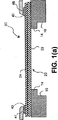
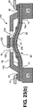
図1は、従来の2点係止式熱アクチュエータの側面視を示す。変形可能な部材20は、2つの対向する係止(アンカー)縁部14にてベース部材10に係止される。図示された変形可能な部材は、2つの層、第1層22及び第2層24からなる薄いビームである。第1層22は、酸化珪素や窒化珪素のような、低い熱膨張係数を有する材料から構成される。第2層24は、金属のような、高い熱膨張係数を有する材料から構成される。図1(a)は、通常の動作温度での定在(休止)時の変形可能な部材20を示す。図示された従来の熱アクチュエータでは、第2の材料は、チタンアルミナイドのような電気抵抗金属であり、電流が層24を通って半田バンプ43,47及びTABボンドリード線41,46のような図示された電気接点を介して流れるときに自己加熱する。電流を印加することによって変形可能な部材を加熱することは、図1(b)に示すように、より熱膨張しやすいそう24に向かう方向に変形可能な部材を変形(曲げ若しくは座屈)させる。
FIG. 1 shows a side view of a conventional two-point locking thermal actuator. The
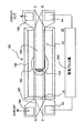
図2(a)及び図2(b)は、本発明による2点係止式熱アクチュエータ15の側面視を示す。図2(a)では、2点係止式熱アクチュエータは、休止の第1位置にある。図2(b)では、変形可能な部材は、第2層24における電気抵抗材料に電流を通すことによって加熱され、温度が上昇し、変形可能な部材が第2の釣り合い(平衡)形状まで曲げられ若しくは座屈させられる。第2層24は、係止部24a及び中央部24cを有するように図示されている。本発明の重要な局面は、変形可能な部材の曲げ剛性が、係止縁部14に近傍の係止部18において、中央部19の曲げ剛性に比べて低減されることである。機械的な低減は、係止部18における曲げ剛性が変形可能な部材20の中央部10の曲げ剛性よりも少なくとも20%小さい場合に実質的であるといわれる。
2A and 2B show a side view of the two-point locking
第2層24上の第3層26は、図2にも図示されている。この層は、2点係止式熱アクチュエータの特別な用途に依存して多様な機能を有することができる。液滴放出器若しくは微小バルブで用いられるとき、第3層26は、適切な化学的耐性及び電気的絶縁性を有する不活性化層であってよい。マイクロスイッチでの使用に対しては、第3層26は、絶縁性のある副層及び導電性のある副層を有する多層積層体であってよい。第3層26は、第1層22から見て第2層24の反対側に設けられるので、その曲げ剛性が変形可能な部材の熱曲げを阻害しないことが重要である。第3層は、典型的には、第1層22若しくは第2層24よりも実質的に低い厚さで設けられ、実現可能な場合には、非常に低いヤング率を有する材料を用いる。
The
変形可能な部材20は、図2に示す3層からなって図示されている。本発明の実際の実現は、製造上の理由若しくは追加の保護及び不活性化のために導入される追加の層を含んでよい。また、考えられることとして、図示された層の任意の層は、改善された性能若しくは製造上の利点のために複数の副層からなってもよい。本発明の全ての実施例は、実質的に異なる熱膨張係数を有する第1及び第2層22,24を有する特徴を共有し、これにより、加熱されたときに熱−機械変形を提供する。例えば上層26のような他の層は、信頼性の改善を含め、更なる有利な機能を提供するために設けられてよい。
The
本発明のある好ましい実施例では、より小さい係止部剛性は、第2層の係止部を、第2層の中央部を形成する材料よりもヤング率が実質的に小さい材料を用いて形成することによって、達成される。例えば、第2層24の係止部24aは、アルミニウムで形成されてよく、中央部24cは、チタンアルミナイドで形成されてもよい。係止部において変形可能な部材の中央部よりも小さい剛性を達成する他のアプローチは、変形可能な部材の係止部におけるより薄い層若しくはより狭い実効幅を含む。
In one preferred embodiment of the present invention, the lower locking portion stiffness is formed by using a material having a substantially lower Young's modulus than the material forming the central portion of the second layer. To achieve. For example, the locking
図2及び他の図における2点係止式熱アクチュエータ15のジオメトリは、典型的な微小ビーム構造に対するスケールに従っていない。典型的には、第1層22及び第2層24は、厚さ数ミクロンで形成され、2点係止式変形可能な部材20の長さは、100ミクロンより大きく、典型的には、300ミクロンより小さい。
The geometry of the two-point locking
変形可能な部材の挙動の根底をなす物理のより詳細な理解は、2つの係止ポイントで支持されるビームを支配する偏微分式の解析によりアプローチされることができる。以下の座標及び幾何学上のパラメータは、図2に示される。変形可能な部材20は、対向する係止縁部14で基板10に係止されるビームである。変形可能な部材に反った軸は、“x”で指示され、左側の係止縁部14でx=0であり、変形可能な部材の中心でx=Lであり、右側の係止縁部14でx=2Lである。更に、変形可能な部材の係止部18と中央部19の間の境界は、近似的であり、各係止縁部から距離Laに位置する。係止部と中央部の間の境界は、本発明により実際に構築された変形可能な部材が、剛性が中央部の実効値から係止部の実効値に変化するまでの有限遷移領域を有することになることは、理解されるべきである。x軸に垂直なビームの撓みは、f(x)で示される。図示された対称のビームの変形は、中心に関して対称であり、それ故に、軸から離れる最大撓みfmaxは、x=Lに位置し、即ちfmax=f(L)である。
A more detailed understanding of the physics underlying the behavior of the deformable member can be approached by analysis of partial differential equations governing the beam supported at the two locking points. The following coordinate and geometric parameters are shown in FIG. The
図示された変形可能な部材20は、厚さh1の第1層22及び厚さh2の第2層24からなる。対向する係止縁部14間の微小ビームの長さは、2Lである。実際に実現されるビームは、また、有限の幅wを有することになる。図2の側面視は、幅寸法を示していない。幅寸法は、幅が変形可能な部材の横断方向で一定である構成に対して本発明の理解に重要でない。しかし、本発明のある好ましい実施例では、変形可能な部材の幅、若しくは、変形可能な部材のある層の幅は、曲げ剛性を低減するために係止部において狭くされてもよい。
The illustrated
図2におけるx軸は、対向する係止縁部位置14間の空間を端から端まで延在して示されている。x軸は、ここで変形可能な部材20の中心面と称される面内に位置する。この面は、残留の変形若しくは座屈の無い平らな変形可能な部材の部分を示す。
The x-axis in FIG. 2 is shown extending from end to end in the space between opposing locking edge positions 14. The x-axis is located in a plane referred to herein as the center plane of the
振動するビームの小さな振動に対する標準式は、以下の通りであり、 The standard formula for small vibrations of an oscillating beam is:

本発明のある好ましい実施例に対して、一以上の層jの幅は、変形可能な部材20の中央部10に対して係止部18において有意に狭くされてよい。それ故に、実効ヤング率Ejは、上記式4における各層に対して、j番目の層の各幅部分wjiのヤング率Ejiを積算し、変形可能な部材の全体の幅wにより正規化することによって、算出される。例えば、層が半分だけ狭くされている場合、当該層の実効ヤング率Ejは、嵩材料のヤング率地の半分まで低減されることになる。このように異なる実効層幅を考慮することは、以下の解析を均一な幅を有する変形可能な部材に対するモデルを用いて進めることを可能とする。係止部18の全体としての幅waが中央部の幅wcに対して低減される場合、これは、解析において、式2の剛性Dを評価するときにwに対して、それぞれの全体の幅wa若しくはwcを用い、式4において実効層ヤング率値Ejを用いることによって、考慮されることができる。
For certain preferred embodiments of the present invention, the width of one or more layers j may be significantly narrowed at the locking
標準式1は、加熱、残留歪及び取り付け接続部によりビーム端部に掛かるモーメントを考慮する境界条件に起因したビームの圧縮若しくは膨脹を含む幾つかの追加の物理作用を考慮するために修正される。 Standard 1 is modified to take into account several additional physical effects including beam compression or expansion due to boundary conditions that take into account heating, residual strain and moments applied to the beam ends by attachment connections. .
拘束される微小ビームを加熱する主な作用は、圧縮応力である。加熱された微小ビームは、拘束されていない場合には、膨脹するだろう。膨脹に対してビームを拘束する際、取り付け接続部は、対向する係止縁部14間の微小ビームを圧縮する。微小ビームの未変形の形状に対して、この熱により誘起される応力は、次の項を式1の形態に付加することによって表される。 The main effect of heating the confined microbeam is compressive stress. The heated microbeam will expand if not constrained. When constraining the beam against expansion, the attachment connection compresses the microbeam between the opposing locking edges 14. For the undeformed shape of the microbeam, this thermally induced stress is expressed by adding the following terms to the form of Equation 1.
しかし、微小ビームは、均一に圧縮されない。それは、外向きに曲がって変形され、変形は、圧縮を緩和することになる。
微小ビームの局部膨脹は、次の通りである。
However, the micro beam is not uniformly compressed. It is bent outwardly and deformed, and the deformation will ease the compression.
The local expansion of the microbeam is as follows.
式14は、固定温度Tで平衡形状f(x)の項の改変であり、次の微分方程式を生む。
本発明は、変形された部材の温度が上昇するにつれて生ずる膨脹座屈の事前バイアス方向に対して作用する内部熱−機械力が発生されることを必要とする。必要とされる力は、不均質構造により達成され、不均質構造は、典型的には、異なる熱−機械特性を有する、特に実質的に異なる熱膨張係数を有する複数材料からなる平らな積層体である。図2に示す2層部材に対して、第1層22及び第2層24の熱膨張係数が実質的に異なる一方でそれらそれぞれのヤング率の値が類似する場合に、有効な熱モーメントcTが、上昇温度Tで発生することになる。
The present invention requires that an internal thermo-mechanical force acting on the pre-bias direction of expansion buckling that occurs as the temperature of the deformed member increases is generated. The required force is achieved by a heterogeneous structure, which is typically a flat laminate composed of a plurality of materials having different thermo-mechanical properties, in particular having substantially different coefficients of thermal expansion. It is. In the case where the thermal expansion coefficients of the
熱モーメントは、構造を平衡形状に曲げる作用をし、平衡形状では、熱膨張係数の大きい方の層が曲げの外側である。それ故に、第2層24が、第1層22の熱膨張係数よりも有意に大きい熱膨張係数を有する場合、熱モーメントは、変形可能な部材20を図2の上向きに曲げるように作用することになる。
The thermal moment acts to bend the structure into an equilibrium shape, where the layer with the higher coefficient of thermal expansion is outside the bend. Therefore, if the
2次元積層構造の熱モーメント係数cは、次のように、積層体を構成する層の厚さ及び材料特性から見出すことができる。 The thermal moment coefficient c of the two-dimensional laminated structure can be found from the thickness and material characteristics of the layers constituting the laminated body as follows.
変形可能な部材の特性、加熱、及び作動荷重がx=Lに関して対称である限り、“半ビーム”の解析、即ちx=0からLの区間上の微分式は、全体の変形可能な部材20の挙動を捕捉することになる。本発明は、変形可能な部材の中心に関して力及び特性における対称性の簡易仮定をなすことにより理解されてもよい。ここでは、以下、式16は、図2に示した変形可能な部材20に適用され、この場合、変形可能な部材の特性及び力は、空間範囲x=LaからLに亘る中央部19に対する値に比べて、空間範囲x=0からLaに亘る係止部18に対して異なる値を有してよい。これは、対称な変形可能な部材20の左側である。右側は、左側の解析に対称な結果を示すことになる。
As long as the properties of the deformable member, the heating, and the operating load are symmetric with respect to x = L, the “half beam” analysis, ie the differential equation over the interval x = 0 to L, gives the overall
図2の変形可能な部材20の左側に上記式を適用すると、次の平衡微分方程式及び関連する境界条件のセットは、周囲よりも高い特定の平衡温度Tに対する変形可能な部材の撓みないし形状f(x)を表す。
Applying the above equation to the left side of the
適用可能な境界条件は次の通りであり、 The applicable boundary conditions are as follows:
上記のx=0、L及びLaで境界条件を備える非線形微分方程式は、次の変数xの変形を用いて数学的により容易に解かれる。 Nonlinear differential equations with the boundary conditions in the above x = 0, L and L a are easily solved by mathematically using a variant of the following variables x.
好ましい材料及び層の一例の設計は、数値計算を介してモデル化された。この例の変形可能な部材は、5層からなった。第1層22は、2つの副層、即ち0.3μmの厚さのβ−炭化珪素(β−SiC)から形成される副層22a、及び、0.2μmの厚さの酸化珪素(SiO2)から形成される副層22bからなった。第2層24は、係止部18及び中央部19に対して異なる特性を付与するために層24内に部位24a及び24cに構成される、2つの材料、即ち1.5μmの厚さのアルミニウム(Al)若しくはチタンアルミナイド(TiAl)からなった。第3層26は、2つの副層、即ち0.5μmの厚さの酸化珪素(SiO2)から形成される副層26a、及び、0.3μmの厚さのテフロン(登録商標)(PTFE)から形成される副層26bからなった。
An example design of preferred materials and layers was modeled through numerical calculations. The deformable member in this example consisted of 5 layers. The
モデル化された変形可能な部材は、全体で3.8μmの厚さであった。全体の長さ2Lは、300μmであり、全ての層が同一の幅30μmを有していた。実効ヤング率、密度及び熱膨張係数の値は、上記の式3乃至式9を用いて計算されることができる。モデル計算で用いられた材料値及び計算された実行パラメータは、表1に与えられる。
The modeled deformable member had a total thickness of 3.8 μm. The
第2層24全体にチタンアルミナイドを有するモデル構成であるケース2に対する式25乃至30の数値解の結果が、図3にプロットされている。プロットは、中央部19が周囲温度よりも高い温度T、100℃に達するまで加熱された後の変形可能な部材20の左側の計算された平衡形状f(x)を示す。変形量f(x)は、変形可能な部材に沿った位置xと同様、ミクロンの単位で表現される。変形された部材20は、対称形状を有すると仮定され、従って、右側が相補形を有するだろう。最大の変形fmaxは、ビーム中心x=150μmで生ずる。
The results of the numerical solutions of
個々の曲線210乃至222は、係止部から中央部への遷移の異なる位置、即ちLaに対する異なる値をプロットする。各曲線と関連付けられたLaの値は、次の通りである。曲線210(La=5/6L)、曲線212(La=4/6L)、曲線214(La=3/6L)、曲線216(La=2/6L)、曲線218(La=1/4L)、曲線220(La=1/5L)、及び曲線222(La=1/6L)。
このケース2の構成に対して、変形可能な部材20の係止部18及び中央部19は、同一の機械的特性を有する。結果として、最大変形の異なる量は、中央部のみが加熱され、中央部のみが荷重Pを受けるという仮定から生じている。これらの仮定は、ヒータが中央部のみで実効的となるようにパターン化され且つ荷重が変形可能な部材20の中心で最も大きい抵抗を印加するように構成されているケースに近似する。後者の条件は、以下の図7及び図8に示す液体室の砂時計形状により液滴生成器に対して伝えられる。室は、変形可能な部材20の中央部19を囲繞して最も収縮されるので、主要な流体の逆圧荷重は、中央部19に印加されることになる。図3のプロット図を研究することにより、ケース2に対しては、最大変形量を最大化するに対する最適な選択肢、即ちL=La=1/4Lに対してfmax≒2.27μmが存在することが理解できる。
With respect to the configuration of the case 2, the locking
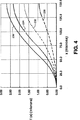
第2層24の係止部24aに対してアルミニウムを有し中央部24cに対してチタンアルミナイドを有するモデル構成であるケース1に対する式25乃至30の数値解の結果が、図4にプロットされている。プロットは、中央部19が周囲温度よりも高い温度T、100℃に達するまで加熱された後の変形可能な部材20の左側の計算された平衡形状f(x)を示す。変形量f(x)は、変形可能な部材に沿った位置xと同様、ミクロンの単位で表現される。変形された部材20は、対称形状を有すると仮定され、従って、右側が相補形を有するだろう。最大の変形fmaxは、ビーム中心x=150μmで生ずる。
The results of the numerical solutions of
個々の曲線230乃至236は、係止部から中央部への遷移の異なる位置、即ちLaに対する異なる値をプロットする。各曲線と関連付けられたLaの値は、次の通りである。曲線230(La=5/6L)、曲線232(La=4/6L)、曲線234(La=3/6L)、及び曲線236(La=2/6L)。
このケース1の構成に対して、変形可能な部材20の係止部18及び中央部19は、異なる機械的特性を有する。特に、係止部は、ケース1ではケース2に比べて剛性が低い。これは、表1における実効ヤング率の値を比べることにより理解できる。ケース1では、実効ヤング率が114GPaであり、ケース2の194GPaの実効ヤング率よりも約40%小さい。図4の曲線230乃至236により表される異なる量の最大変形は、係止部18における低減された曲げ剛性と共に、中央部のみが加熱され且つ中央部のみが荷重Pを受けるという仮定から生ずる。
With respect to the configuration of the case 1, the locking
ケース1の変形可能な部材の最大変形量は、L=La=1/3Lに対してfmax≒2.69μmである。係止部における曲げ剛性を40%低減することは、最大変形量の18%の増加をもたらした。 The maximum deformation amount of the deformable member of case 1 is f max ≈2.69 μm with respect to L = L a = 1 / 3L. Reducing the bending stiffness at the locking part by 40% resulted in an 18% increase in the maximum deformation.
図3及び図4におけるプロットされた結果は、2次元解析に基づいていた。3次元数値解析も、ケース1及びケース2の構成の変形可能な部材20に対して実行された。ESI CFD社による数値解析器CFD−ACE*が、3次元解析に用いられた。このソフトウェアパッケージは、インターネットのウェブサイトwww.esi-group.comにて入手可能である。
The plotted results in FIGS. 3 and 4 were based on a two-dimensional analysis. A three-dimensional numerical analysis was also performed on the
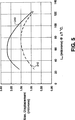
3D計算は、係止部から中央部への遷移位置Laの関数としてf(L)=fmaxの値を求めるために実行された。モデルに対する式25乃至30のこれらの3次元数値解の結果は、図5にプロットされている。図5のプロット240は、第2層の中央部24aがアルミニウムで形成されたケース1に対してである。図5のプロット242は、第2層の中央部24aがチタンアルミナイドで形成されたケース2に対してである。3次元計算は、2次元解析が変形量を過大に評価することを示す。しかし、3次元計算は、また、係止部18における剛性を低減する比例的な効果が、2次元解析により過小に評価されることを示す。図5のプロット240及び242は、係止部18における剛性の40%までの低減は、最大変形量の40%までの増加を生むこと、即ちfmaxが1.51μmから2.2μmまで増加することを示す。
A 3D calculation was performed to determine the value of f (L) = f max as a function of the transition position La from the locking part to the central part. The results of these three-dimensional numerical solutions of equations 25-30 for the model are plotted in FIG. The
図5のプロットは、明らかに、係止縁部14に近傍の2点係止式熱アクチュエータの変形可能な部材20の部位の曲げ剛性を低減することによって達成可能な最大変形量の増加を実証している。入力される同一のエネルギに対する変形量の改善は、係止部間の距離を増加するため、使用されるエネルギの全体量を低減するため、若しくは、作動の繰り返し周期を増加させるために、利用されてよい。
The plot of FIG. 5 clearly demonstrates the maximum amount of deformation that can be achieved by reducing the bending stiffness of the portion of the
改善の量は、上述の多くの材料、形状及び幾何因子に依存する。上述の解析されたモデルの変形可能な部材20における曲げ剛性を低減する手段は、第2層24の一部を、実質的に低いヤング率を有する材料で置き換えることであった。式2,25乃至30を精査することから理解できるように、曲げ剛性パラメータDを低減する任意の手段は、所与のエネルギ入力に対する改善された変形をもたらすことになる。曲げ剛性を低減する手段は、実効厚さhを低減すること、実効幅wを低減すること、実効ヤング率Eを低減すること、若しくはこれらの任意の組み合わせを含む。
The amount of improvement depends on the many materials, shapes and geometric factors mentioned above. The means for reducing the bending stiffness in the
これより、係止位置近傍の曲げ剛性が低減された2点係止式熱アクチュエータの幾つかの微小装置への適用例が議論される。本発明は、特にインクジェットプリントヘッドである液滴放出器、液体微小バルブ及び電気微小スイッチへの、かかる熱アクチュエータの組み込みを含む。 Thus, examples of application of the two-point locking thermal actuator with reduced bending rigidity near the locking position to several micro devices will be discussed. The present invention includes the incorporation of such thermal actuators, particularly in droplet ejectors, liquid microvalves and electrical microswitches that are inkjet printheads.
図6を参照するに、本発明による装置を使用してよいインクジェット印刷システムの概略図が示されている。システムは、液滴を印刷するためのコマンドとしてコントローラ300により受信される信号を供給する画像データ源400を含む。コントローラ300は、電気パルス源200に信号を出力する。パルス源200は、電気エネルギパルスからなる電圧信号を生成し、電圧信号は、インクジェットプリントヘッド100内の各2点係止式熱アクチュエータ15に対応付けられた電気抵抗手段に印加される。電気エネルギパルスは、2点係止式熱アクチュエータ15を迅速に変形させ、ノズル30位置のインクを加圧し、受像体500上に着地するインク液滴50を放出する。
Referring to FIG. 6, there is shown a schematic diagram of an ink jet printing system that may use an apparatus according to the present invention. The system includes an
図7は、インクジェットプリントヘッド100の平面視を示す。熱作動式インクジェットユニット110のアレイは、中央に整列されたノズル30及びインク室12を有して示されている。インクジェットユニット110は、超小型電子部品製造方法を用いて基板内及び基板上に形成される。
FIG. 7 shows a plan view of the
各液滴放出ユニット110は、対応する電気ヒータ電極接点42,44を有し、電気ヒータ電極接点42,44は、2点係止式熱アクチュエータの変形可能な部材20の第2層内に形成され、後述の如く熱−機械作用に参加する電気抵抗ヒータと一体に形成され、若しくは、電気抵抗ヒータに電気的に接続される。本実施例の電気抵抗は、変形可能な部材20の第2層24に対応し、図7の平面視では別個に見えない。プリントヘッド100の部材80は、微小電子基板10、及び、液体供給、電気信号及び機械的インターフェース機能を相互接続する他の手段に対する搭載面を提供する。
Each
図8(a)は、単一の液滴放出ユニット110の平面視を示し、2番目の平面視図8bは、ノズル30を含む液室カバー28が除去されている。
FIG. 8A shows a plan view of the single
図8aに架空的に示される2点係止式熱アクチュエータ15は、図8(b)において実線で見ることができる。2点係止式熱アクチュエータ15の変形可能な部材20は、基板10内の凹部(くぼみ)として形成される液体室12の対向する係止縁部14から延在する。変形可能な部材の固定部20bは、基板10に結合され、変形可能な部材を係止する。
The two-point locking
アクチュエータの変形可能な部材20は、長くて薄い幅広のビームの形状を有する。この形状は、使用できる2点係止式熱アクチュエータ用の変形可能な部材の単なる例である。多くの他の形状が適用可能である。本発明のある実施例に対して、変形可能な部材は、その外周まわりで連続的にベース部材に取り付けられるプレートである。
The
図8では、液体室12は、2点係止変形中にアクチュエータの移動に対するクリアランスを提供するために離間された、変形可能な部材20の中央部19に対応する狭い壁部を12cに有する。2点係止式熱アクチュエータの最大変形が生ずる室12の壁の閉じ位置は、ノズル30で液滴放出に効果的に影響するように生成された圧力インパルスを集中させる補助をする。
In FIG. 8, the
図8(b)は、ヒータ電極42及び44での電気抵抗ヒータ(変形可能な部材20の第2層に対応する)への電気パルス源200の取り付けを概略的に示す。電圧差が、抵抗を解して抵抗加熱を引き起こすために電圧端子42及び44に印加される。これは、電流Iを示す矢印により一般的に指示される。図8の平面視では、変形可能な部材20の中央部19は、電気的に脈動され、その中心面から外向きに座屈するとき、図を見る人に向かう方向に移動する。液滴は、カバー28内のノズル30から図を見る人に向かう方向に放出される。この作動及び液滴放出のジオメトリは、多くのインクジェット開示において“ルーフシューター(roof shooter)”と呼ばれている。
FIG. 8 (b) schematically shows the attachment of the
図9は、本発明の好ましい実施例による2点係止式熱アクチュエータの側面視を示す。図9(a)では、変形可能な部材20は、第1の休止位置にある。図9(b)は、第2位置へと上向きに座屈された変形可能な部材を示す。変形可能な部材20は、2点係止式熱アクチュエータに対するベース部材として機能する基板10に係止される。
FIG. 9 shows a side view of a two-point locking thermal actuator according to a preferred embodiment of the present invention. In FIG. 9A, the
液滴放出器におけるアクチュエータとして用いられるとき、変形可能な部材の座屈応答は、ノズルでの液体を十分に加圧するほど迅速でなければならない。典型的には、電気抵抗加熱装置が、熱パルスを印加するように適合される。10μsecより短い電気パルス持続時間が用いられ、好ましくは、2μsecより短い持続時間が用いられる。 When used as an actuator in a drop emitter, the buckling response of the deformable member must be fast enough to pressurize the liquid at the nozzle. Typically, an electrical resistance heating device is adapted to apply a heat pulse. An electrical pulse duration of less than 10 μsec is used, preferably a duration of less than 2 μsec.
図10乃至図16は、本発明の好ましい実施例の幾つかによる単一の液滴放出器を構成するための製造処理ステップを示す。これらの実施例に対して、第2層24は、チタンアルミナイドのような、電気的に抵抗のある材料を用いて構成され、電流Iを搬送する部位が、抵抗内にパターン化される。第2層24の係止部24aは、変形可能な部材20の係止部18の曲げ剛性を有意に低減し且つ中央部に加熱領域を閉じ込めるため、アルミニウムのような、より柔軟な伝導性材料で置換される。
10-16 illustrate manufacturing process steps for constructing a single droplet emitter according to some of the preferred embodiments of the present invention. For these embodiments, the
図10は、微小電気機械処理シーケンスの初期ステージにおける、例えば単結晶シリコンである微小電子部品材料基板10を示す。図示された製造シーケンスでは、基板10は、2点係止式熱アクチュエータのベース部材10になる。不活性化層21は、酸化物、窒化物、ポリシリコン若しくはその類のような材料であってよく、製造シーケンスの終了付近で後方側のエッチングに対するエッチングストッパとして機能もする。エッチング可能な領域62は、最終の変形可能な部材まわりの液体補充を提供し、変形可能な部材を解放するため、層21内に開口される。
FIG. 10 shows a microelectronic
図10は、また、事前に用意された基板上に堆積及びパターン化された将来の変形可能な部材の第1層22を示す。第1層22に対して用いられる第1材料は、低い熱膨張係数を有し、比較的高いヤング率を有する。第1層22に適する典型的な材料は、珪素の酸化物若しくは窒化物、及びβ型炭化珪素である。しかし、多数の微小電子部品材料は、強い熱モーメントを生成する補助をし、ひずんだときに弾性エネルギを貯める第1層22の機能を提供する。第1層22は、また、一以上の副層からなってもよい。多数の微小アクチュエータ装置の用途に対して、第1層は、厚さが数ミクロンとなるだろう。
FIG. 10 also shows a
図11は、第1層の上に被覆される将来の変形可能な部材の第2層24の形成を図示する。第2層24は、金属のような、大きい熱膨張係数を有する第2材料から構成される。大きな熱モーメントを生成し、且つ、2点係止式熱アクチュエータに対する弾性エネルギの蓄積を最大化するために、好ましくは、第2材料は、第1材料と同等のヤング率を有する。本発明に対して好ましい第2材料は、チタンアルミナイド金属間化合物である。チタンアルミナイド金属間化合物の堆積は、例えばRF若しくはパルスDCマグネトロンスパッタリングにより、実行されてよい。図10乃至16に示した本発明の実施例に対して、第2層24は、また、変形可能な部材20の中央部19及び第2層24の中央部24cも画成するレジスタパターンを形成する電気抵抗である。
FIG. 11 illustrates the formation of a
図12は、アルミニウムのような柔軟な金属材料の追加により第2層24の形成の完成を示す図である。この材料は、第2層24の係止部24aを形成する。アルミニウムは、また、第2層の中央部24cとして形成される電気抵抗材料への電気接続を形成する。
FIG. 12 shows the completion of the formation of the
図13は、変形可能な部材の前に形成された層上への第3層の形成の完成を示す図である。上述の如く、第3層26は、多様の機能のために用いられてよい。図10乃至図16において製造されているインクジェットプリントヘッド用途に対しては、第3層26は、インク(作動流体)との化学的及び電気的反応からの変形可能な部材の保護を提供する。第3層は、酸化物及び有機コーティングの双方のような、異なる材料の副層からなってよい。
FIG. 13 shows the completion of the formation of the third layer on the layer formed before the deformable member. As described above, the
第3層26は、電気接点電極42,44を提供するように窓が開けられる。ヒータ電極42,44は、第1層22及び不活性化層21(図13に示されず)を介して貫通する基板10に事前に形成された回路に接触してよい。或いは、ここで図示されるように、ヒータ電極42,44は、Tape Automated Bonding(TAB)やワイヤ結合のような、他の標準的な電気接続方法により外部的に接触されてもよい。
The
本発明の代替実施例は、変形可能な部材に熱パルスを印加するために追加の電気抵抗素子を利用する。この場合、かかる素子は、第1層22及び第2層24の間若しくは第2層24の上方に配置される一以上の追加の積層体として構成されてもよい。熱膨張する層である第2層24への直接的な熱パルスの印加は、第2層及び第1層22の間の熱望調査を最大化することによって最大の熱モーメントを促進する上で利点がある。しかし、電気抵抗ヒータ素子を含む追加の積層体は、変形可能な部材の全体の熱−機械挙動に寄与するので、第2層24の上方若しくは下方の、これらの積層体の最も好ましい位置付けは、追加の層の機械的な特性に依存する。
Alternative embodiments of the present invention utilize an additional electrical resistance element to apply a heat pulse to the deformable member. In this case, the element may be configured as one or more additional laminates disposed between the
図14は、液滴放出器の室の内部の形状へと形成される犠牲層29の追加を示す。犠牲層29は、前に堆積された層上に形成される。この目的のために適した材料は、ポリイミドである。ポリイミドは、第1層22、第2層24、第3層26及び種々の目的のために追加された追加層のトポグラフィーを有する表面を平坦化するためにも、十分な深さで装置基板内に付与される。近傍の材料に対して選択的に除去されることができる任意の材料が、犠牲構造29を構成するために用いられてよい。
FIG. 14 shows the addition of a
図15は、犠牲層構造29上に、プラズマ堆積される酸化珪素、窒化珪素若しくはその類のような、コンフォーマル材料を堆積することによって形成されるカバー28及び液滴放出器の上室の壁を示す。この層は、液滴放出器室を完成させるためにパターン化され、基板10のエッチング部位により追加的に形成されることになり、図7及び図8において室12として指示される。ノズル30は、液滴放出器の上室28に形成され、製造シーケンスのこの段階では液滴放出器の上室内のままである犠牲材料層29に連通する。
FIG. 15 shows a
図16(a)乃至図16(c)は、図15のA−Aで指示される断面を通る装置の側面視を示す。図16(a)では、犠牲層29は、ノズル開口30を除く液滴放出器の上室壁28内に収容されている。また、図16(a)に示すように、基板10は手が付けられていない。図16(b)では、基板10は、変形可能な部材20まわり及び周辺の液体室領域12(図10乃至図13参照)及び変形可能な部材20の下方が除去される。除去は、使用される基板が単結晶シリコンである場合に対して配向依存エッチング、反応性イオンエッチング、若しくは、ウエット及びドライエッチング方法のある組み合わせのような、異方性エッチング処理によりなされてよい。2点係止式熱アクチュエータ単独を構成するためには、犠牲構造及び液体室ステップは必要でなく、基板10のエッチング除去のステップは、変形可能な部材を解放するために用いられてよい。
16 (a) to 16 (c) show a side view of the device through the cross section indicated by AA in FIG. In FIG. 16A, the
図16(c)では、犠牲層29が、ポリイミドの使用の場合に酸素及びフッ素源を用いたドライエッチングにより除去されている。エッチング剤ガスは、ノズル30を介して、基板の裏側から前にエッチングされた、新たに開口された流体供給室領域12から入る。このステップは、変形可能な部材20を解放し、液滴放出器構造の製造が完了する。
In FIG. 16C, the
図10乃至図16は、好ましい製造シーケンスを示す。しかし、多くの他の構成アプローチが、広く知られた微小電子部品製造プロセス及び材料を用いて追従されてもよい。本発明の目的のため、第1層22、第2層24を含み、係止部18の曲げ剛性が変形可能な部材20の中央部19の曲げ剛性よりも実質的に小さい変形可能な部材を生む任意の製造アプローチが追従されてもよい。更に、図10乃至図16の図示されたシーケンスでは、液滴放出器の室壁12,28及びノズル30は、基板10上の位置に形成されていた。或いは、2点係止式熱アクチュエータは、別に構成され、液滴放出器を形成するために液体室構成要素に結合されることも可能でありうる。
10 to 16 show a preferred manufacturing sequence. However, many other configuration approaches may be followed using well-known microelectronic component manufacturing processes and materials. For the purpose of the present invention, a deformable member that includes the
図10乃至図16は、第2層が電気抵抗材料で形成される好ましい実施例を示す。第2層24の一部は、電気パルスが対のヒータ電極42,44に印加されるときに電流を搬送する同時抵抗部位へと形成され、これにより、第2層24を直接加熱する。本発明の他の好ましい実施例では、第2層24は、変形可能な部材に熱を印加するように適合された他の装置により加熱される。例えば、薄膜抵抗構造は、第1層22上に形成され、次いで、その上に第2層24が形成されてもよい。或いは、薄膜抵抗構造は、第2層24の上部上に形成されることができる。
10-16 illustrate a preferred embodiment in which the second layer is formed of an electrically resistive material. A portion of the
熱は、電気抵抗以外の装置により第2層24に導入されてもよい。光エネルギのパルスは、変形可能な部材の第1及び第2層により吸収され、若しくは、光エネルギの特定のスペクトルの効率的な吸収対として機能する特別に付加された追加の層により吸収されうる。熱パルスを印加するための光エネルギパルスの使用は、本発明による2点係止式熱アクチュエータ微小バルブに関連して以下の図20において図示される。変形可能な部材に熱エネルギのパルスを伝達するように適合されることができる任意の装置が、本発明を実現するための実行可能な手段として考えられる。
Heat may be introduced into the
本発明による2点係止式熱アクチュエータは、流体微小バルブの構成において有用である。常態閉の流体微小バルブ構成は、図17に示され、常態開の流体微小バルブ構成は、図18に示されている。常態閉及び常態開のバルブ構成の双方に対して、2点係止式熱アクチュエータは、顕著に改善されたエネルギ効率若しくは最大撓みの理由により効果的である。 The two-point locking thermal actuator according to the present invention is useful in the construction of fluid microvalves. A normally closed fluid microvalve configuration is shown in FIG. 17, and a normally open fluid microvalve configuration is shown in FIG. For both normally closed and normally open valve configurations, the two-point locking thermal actuator is effective for reasons of significantly improved energy efficiency or maximum deflection.
常態閉の微小バルブは、図17(a)に示すように構成されてよく、従って、変形可能な部材20がその休止位置にあるとき第2層22は流体フローポート32に対して付勢される。図示されたバルブ構成では、バルブシーリング部材38は、第1層22上に担持されている。バルブシーリング部材38は、バルブシート36に対して密接する。不活性化層21は、第1層22が不活性化機能を実現できるので、このバルブ構成に対しては省略されている。図示された構成では、流体は、図8の上に図示されたインクジェット液滴生成器室用に図示されるような変形可能な部材まわりの入口経路(図示せず)を介して圧力下で源から入れられる。熱パルスが変形可能な部材20に印加されるとき、バルブが最大に開き、ストリーム52(図17(b))を放出する。バルブは、上向きに座屈した状態を維持するために変形可能な部材の加熱を継続することによって、開状態に維持されることができる。
The normally closed microvalve may be configured as shown in FIG. 17 (a) so that the
状態開の微小バルブは、図18(a)に示すように構成されてもよい。変形可能な部材20は、流体フローポート32の近傍に配置され、変形可能な部材20の座屈変形がフローポート32を閉じるために十分であるように、流体フローポート32の十分近くに配置される。図18には図示されていないが、バルブシーリング部材は、変形可能な部材20により担持されうり、バルブシートは、図17に示す常態閉の微小バルブに同様の態様で設けられうる。熱パルスが変形可能な部材に印加されるとき、バルブは、流体フローポート32に向けて変形可能な部材を付勢することによって閉じる。バルブは、上向きに座屈した状態を維持するために変形可能な部材の加熱を継続することによって、閉状態に維持されることができる。
The micro valve in the open state may be configured as shown in FIG. The
上述の2点係止式熱アクチュエータ、液滴放出器及び微小バルブの説明は、対向する係止縁部に両端が半剛結で取り付けられる薄い長方形の微小ビームの形状で変形可能な部材を示してきた。変形可能な部材の長い縁部は、取り付けられず、自由に動き、2次元の座屈変形を生む。或いは、変形可能な部材は、完全に閉じた外周まわりに取り付けられるプレートとして構成されてもよい。 The description of the two-point locking thermal actuator, drop ejector and microvalve described above shows a deformable member in the form of a thin rectangular microbeam that is semi-rigidly attached to opposite locking edges at both ends. I came. The long edges of the deformable member are not attached and move freely, producing a two-dimensional buckling deformation. Alternatively, the deformable member may be configured as a plate attached around a completely closed outer periphery.
図19は、その円形の外周まわり全体が取り付けられる円形積層体として構成された変形可能な部材20の平面視を示す。かかる変形可能な部材は、3次元の態様で、座屈ないしパッカーリングする。変形可能な部材の外周完全取り付け型構成は、作動流体内に浸された変形可能な部材を作動させることが望ましいときに効果的となりえる。若しくは、変形可能な部材は、一方の面でエア、真空、若しくは他の低抵抗媒体に対して作動し、反対の面に当たる作動流体の印加に対して変形することも利点となりうる。
FIG. 19 shows a plan view of a
図19(a)は、中央ノズル30を備える正方形流体上室28を有する液滴放出器を示す。図19(a)で架空に示すように、円形の変形可能な部材20は、外周の係止縁部14に接続される。変形可能な部材20は、流体室の底壁の一部を形成する。流体は、入口ポート31を介して室に入る。図19(b)では、上室28が除去されている。熱パルスは、ヒータ電極42、44を介して変形可能な部材20の積層構造内に含まれる電気抵抗層に電流を通すことによって印加される。
FIG. 19 (a) shows a drop emitter having a square fluid
図20は、変形可能な部材が、完全な円形外周まわりが取り付けられた円形積層体である本発明の代替実施例を示す。変形可能な部材は、常態閉の微小バルブの壁の一部を形成する。変形可能な部材の第2層24側は、光収集及び合焦部材40により方向付けられる光エネルギ39にアクセス可能であるように構成されている。流体は、入口ポート31を介して微小バルブに入ることができる。バルブは、十分な強度の光エネルギのパルスを方向付け、2点係止式座屈を引き起こすために適切な温度時間プロフィールにより変形可能な部材を加熱することによって、動作される。バルブは、変形可能な部材の十分に上昇した温度を維持するために十分な光エネルギパルスを供給し続けることによって、開状態に維持されてよい。
FIG. 20 shows an alternative embodiment of the invention in which the deformable member is a circular laminate with a full circular perimeter attached. The deformable member forms part of the wall of the normally closed microvalve. The
本発明による光作動式装置は、完全な電気的及び機械的絶縁が微小バルブの開成中に維持されている点で効果的である。液滴放出器、微小バルブ若しくは他の2点係止式熱アクチュエータ用の光作動式構成は、本発明による同様の態様で設計されてもよい。 The light actuated device according to the invention is advantageous in that complete electrical and mechanical insulation is maintained during the opening of the microvalve. Light actuated configurations for drop emitters, microvalves or other two-point locking thermal actuators may be designed in a similar manner according to the present invention.
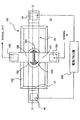
本発明による2点係止式熱アクチュエータは、電気回路を制御する微小スイッチの構成においても有用である。本発明による微小スイッチユニット150の平面視が図21に示されている。図22(a)及び図22(b)は、常態閉の微小スイッチユニット160の側面視を示し、図23(a)及び図22(b)は、常態開の微小スイッチユニット170の側面視を示す。
The two-point locking thermal actuator according to the present invention is also useful in the configuration of a micro switch for controlling an electric circuit. A plan view of the
図21の平面視では、変形可能な部材20は、電気抵抗手段により加熱される。電気パルスは、ヒータ電極42,44を介して電気パルス源200により印加される。微小スイッチは、第1スイッチ電極155と第2スイッチ電極157を介して電気回路を制御する。第1スイッチ電極155及び第2スイッチ電極157は、変形可能な部材20の上の位置にスペーサ支持体152により支持されている。空間159は、第1及び第2スイッチ電極155,157を分離し、従って、スイッチ入力パッド156,158に接続される外部回路は、第1及び第2スイッチ電極が電気的に短絡されない限り、オープンである。第1及び第2スイッチ電極155,157の下方の制御電極154は、スペーシング構造152内の電極アクセス開口153を介して短絡接触へと付勢されてもよい。制御電極154は、高い伝導性の材料から構成される。変形可能な部材20は、熱パルスの印加により座屈を受ける際に、第1及び第2スイッチ電極155,157に向かう方向若しくは離れる方向に制御電極を移動させるように配置される。
In the plan view of FIG. 21, the
常態閉の微小スイッチは、図22に示すように構成されてもよい。図22の側面視は、図21のラインC−Cに沿って形成される。変形可能な部材20の第1層22は、変形可能な部材20がその休止形状にあるときに、制御電極154を第1及び第2スイッチ電極155,157(図示せず)に接触するように付勢し、これにより、入力パッド156,158(図示せず)を介して外部回路を閉じる。熱パルスが変形可能な部材20に印加されるとき、微小スイッチは、最大に開き(図22(b))、外部回路を切断し、即ち微小スイッチを開く。微小スイッチは、上向きの座屈状態を維持するために十分に変形可能な部材を加熱し続けることによって開状態に維持されてもよい。
The normally closed micro switch may be configured as shown in FIG. The side view of FIG. 22 is formed along line CC in FIG. The
常態開の微小スイッチは、図23に示すように構成されてもよい。図23の側面視は、図21のラインC−Cに沿って形成される。変形可能な部材20は、電極アクセス開口159の近傍に配置され、座屈後に変形が制御電極154を第1及び第2スイッチ電極155,157(図示せず)に短絡接触するように付勢するほど十分であるように、電極アクセス開口159の十分近くに配置される。熱パルスが変形可能な部材20に印加される時、微小スイッチは、制御電極154を第1及び第2スイッチ電極155,157との電気接触状態へと付勢することによって、閉じる。微小スイッチは、上向きの座屈状態を維持するために十分に変形可能な部材を加熱し続けることによって閉状態に維持されてもよい。第2層24が電気的に抵抗のある本発明の実施例に対しては、電気絶縁層151が、制御電極154の下方に設けられてよい。
The normally open micro switch may be configured as shown in FIG. The side view of FIG. 23 is formed along line CC in FIG. The
図21乃至図23に示す微小スイッチに対しては、第1及び第2スイッチ電極の双方は、スペーシング構造152により支持され、制御電極154は、スイッチを開若しくは閉にするために双方と短絡接触する。第2スイッチ電極154が変形可能な部材20上に形成され、制御電極154との永久的に接触する代替例の微小スイッチ構成が、図24に示される。第1スイッチ電極155は、スペーシング構造152により支持され、電気アクセス開口153を介して制御電極による接触のためにアクセス可能である。本発明のこの図示された実施例では、開閉する微小スイッチは、それ故に、第1スイッチ電極155との接触するように若しくは離反するように制御電極154を付勢する変形可能な部材20から得られる。
For the microswitch shown in FIGS. 21-23, both the first and second switch electrodes are supported by a
図24は、永久電気接点で第2スイッチ電極及び制御スイッチ154を有する構成の代替例の微小スイッチユニット150の平面視を示す。図25(a)は、本発明のこの構成による常態閉の微小スイッチユニット160の側面視を示す。図25(a)は、図24のラインD−Dに沿って形成された側面視であり、定常の常態閉の常態のスイッチを示す。この視では、外部電気回路入力リード線156,158が見えるが、変形可能な部材を加熱する電気抵抗手段に取り付けられるヒータ電極42,44は示されていない。図25(b)は、熱パルスが印加され変形可能な部材が座屈を受けた後の常態閉の微小スイッチユニット160の側面視であり、制御スイッチ154と第1スイッチ電極155の間の空間159を開き、これにより、外部回路をオープンにする。図25(b)は、図24のラインE−Eに沿って形成され、ヒータ電極42,44を示すが、入力電極156,158は示していない。
FIG. 24 shows a plan view of an alternative
上述の2点係止式熱アクチュエータ微小スイッチの説明は、対向する係止縁部に両端が取り付けられる薄い長方形の微小ビームの形状で変形可能な部材を示してきた。変形可能な部材の長い縁部は、取り付けられず、自由に動き、2次元の座屈変形を生む。或いは、変形可能な部材は、微小バルブに対して上記の図19に示したように、完全に閉じた外周まわりに取り付けられるプレートとして構成されてもよい。外周完全取り付け型の変形可能な部材は、制御電極に対向する面側が真空若しくは他の低抵抗ガス内の変形可能な部材を動作させることが望ましいときに効果的となりうる。 The description of the two-point locking thermal actuator microswitch described above has shown a deformable member in the form of a thin rectangular microbeam with both ends attached to opposing locking edges. The long edges of the deformable member are not attached and move freely, producing a two-dimensional buckling deformation. Alternatively, the deformable member may be configured as a plate that is attached to the microvalve around a fully closed perimeter as shown in FIG. 19 above. A perimeter fully mounted deformable member can be effective when it is desirable to operate a deformable member in a vacuum or other low resistance gas on the side facing the control electrode.
図26は、変形可能な部材が、完全な円形外周まわりが取り付けられた円形積層体である常態閉の微小スイッチユニット160の代替実施例の側面視を示す。変形可能な部材の第2層24側は、光収集及び合焦部材40により方向付けられる光エネルギ39にアクセス可能であるように構成されている。微小スイッチは、十分な強度の光エネルギのパルスを方向付け、2点係止式座屈を引き起こすために変形可能な部材を加熱することによって、動作される。微小スイッチは、変形可能な部材の十分に上昇した温度を維持するために十分な光エネルギパルスを供給し続けることによって、開状態に維持されてよい。
FIG. 26 shows a side view of an alternative embodiment of a normally closed
本発明による光作動式装置は、完全な電気的及び機械的絶縁が微小スイッチの開成中に維持できる点で効果的である。常態開の微小スイッチに対する光作動式構成は、本発明による同様の態様で設計されてもよい。 The photoactuated device according to the invention is advantageous in that complete electrical and mechanical insulation can be maintained during the opening of the microswitch. Light actuated configurations for normally open microswitches may be designed in a similar manner according to the present invention.
図27は、係止部18における変形可能な部材20の曲げ剛性を低減する代替設計の平面視を示す。スロット27により図示されるように、係止部における変形可能な部材20の一以上の層から材料が除去されている。この態様の材料の除去は、変形可能な部材20の中央部19に比べて係止部18におけるビーム構造の実効幅を低減することによって、曲げ剛性を低減する。
FIG. 27 shows a plan view of an alternative design that reduces the bending stiffness of the
図28は、係止部18における変形可能な部材20の曲げ剛性を低減する代替設計の側面視を示す。図示された2点係止式熱アクチュエータに対しては、第1層22は、係止部において完全に除去されている。この態様での材料の除去は、実効厚さ及び実効ヤング率の双方を係止部18において低減することによって、曲げ剛性を低減する。
FIG. 28 shows a side view of an alternative design that reduces the bending stiffness of the
ここでの各図は、平らで中心面内にあるような変形可能な部材20の休止形状を示している。しかし、上昇若しくは降下される温度からの製造プロセス作用若しくは動作に起因して、変形可能な部材の休止形状は、中心面から弓状に曲げられてもよい。本発明は、変形可能な部材20の休止形状のこの多様性を予期し含んでいる。
Each figure here shows the resting shape of the
上述の説明の多くは、単一の2点係止式熱アクチュエータ、液滴放出器、微小バルブ若しくは微小スイッチに向けていたが、本発明が、かかる単一の装置ユニットの組立体及びアレイを形成することに適用可能であることは、理解されるべきである。また、本発明による2点係止式熱アクチュエータ装置は、他の電子部品及び回路と同時に製造されてもよく、若しくは、電子部品及び回路の製造前後に同一の基板上に形成されてもよい。 Although much of the above description has been directed to a single two-point locking thermal actuator, droplet ejector, microvalve or microswitch, the present invention provides an assembly and array of such a single device unit. It should be understood that it is applicable to forming. In addition, the two-point locking thermal actuator device according to the present invention may be manufactured simultaneously with other electronic components and circuits, or may be formed on the same substrate before and after the manufacturing of the electronic components and circuits.
更に、上述の詳細な説明は、主に、電気抵抗装置、パルス光エネルギにより加熱される2点係止式熱アクチュエータを議論しているが、誘導加熱のような、熱パルスを生成する他の手段が、本発明による変形可能な部材に熱パルスを印加するために適合されてもよい。 In addition, the detailed description above discusses primarily electrical resistance devices, two-point locking thermal actuators that are heated by pulsed light energy, but other heat generating pulses, such as induction heating. Means may be adapted for applying a heat pulse to the deformable member according to the invention.
上述からは、本発明は、目的の全てを得るように良好に適合されたものであることが分かる。本発明の好ましい実施例の上述の説明は、図示及び説明の目的で提示されてきた。本発明を、網羅的であることや開示される正確な形態に限定することは意図されていない。修正及び変形は、可能であり、上述の教示に照らして当業者により認識されるだろう。かかる追加の実施例は、添付の請求項の範囲内に内包される。 From the foregoing it can be seen that the present invention is well adapted to achieve all of its objectives. The foregoing description of the preferred embodiment of the present invention has been presented for purposes of illustration and description. It is not intended to be exhaustive or to limit the invention to the precise form disclosed. Modifications and variations are possible and will be recognized by those skilled in the art in light of the above teachings. Such additional embodiments are within the scope of the appended claims.
10 基板ベース部材
11 液体室狭幅壁部
12 液体室
12c 液体室12の狭幅の中央部
13 柔軟な結合材料
14 変形可能な部材12の係止位置の、対向する係止縁部
15 本発明による2点係止式熱アクチュエータ
17 ベース部材の解放位置
18 変形可能な部材の係止部
19 変形可能な部材の中央部
20 変形可能な部材
20b 基板10に結合される変形可能な部材20の固定部
21 不活性化層及び/又はエッチング停止マスキング層
22 第1層
24 第2層
24a 第2層の係止部
24c 第2層の中央部
26 第3層
27 係止部の変形可能な部材の材料を除去する穴
28 液体室構造、壁及びカバー
29 犠牲層
30 ノズル
31 流体入口ポート
32 流体フローポート
34 流体入口経路
36 バルブシート
38 バルブシーリング部材
40 光方向付け部材
41 TABリード線
42 ヒータ電極
43 半田バンプ
44 ヒータ電極
45 半田バンプ
46 TABリード線
47 電気抵抗部材、薄膜抵抗レジスタ
50 液滴
52 流体ストリーム
60 流体
62 エッチング可能な領域
80 マウンチング構造
90 2点係止式熱アクチュエータの従来の設計
100 インクジェットプリントヘッド
110 液滴放出器ユニット
120 常態閉の微小(マイクロ)バルブユニット
130 常態開の微小(マイクロ)バルブユニット
150 微小(マイクロ)スイッチユニット
151 電極下方の電気絶縁層
152 スペーシング構造
153 電極アクセス開口
154 制御電極
155 第1スイッチ電極
156 第1スイッチ電極への入力パッド
157 第2スイッチ電極
158 第2スイッチ電極への入力パッド
159 第1及び第2スイッチ電極間の空間
160 常態閉の微小(マイクロ)スイッチユニット
170 常態開の微小(マイクロ)スイッチユニット
200 電極パルス源
300 コントローラ
400 画像データ源
500 受信機
DESCRIPTION OF SYMBOLS 10 Substrate base member 11 Liquid chamber narrow wall part 12 Liquid chamber 12c Narrow center part of liquid chamber 12 Flexible coupling material 14 Opposing locking edge 15 of locking position of deformable member 12 15 2-point locking thermal actuator by 17 17 Base member release position 18 Deformable member locking portion 19 Deformable member central portion 20 Deformable member 20b Fixing of deformable member 20 coupled to substrate 10 Part 21 deactivation layer and / or etching stop masking layer 22 first layer 24 second layer 24a second layer locking part 24c second layer central part 26 third layer 27 of locking part deformable member Hole for removing material 28 Liquid chamber structure, wall and cover 29 Sacrificial layer 30 Nozzle 31 Fluid inlet port 32 Fluid flow port 34 Fluid inlet path 36 Valve seat 38 Valve seat 40 directional member 41 TAB lead wire 42 heater electrode 43 solder bump 44 heater electrode 45 solder bump 46 TAB lead wire 47 electric resistance member, thin film resistor resistor 50 droplet 52 fluid stream 60 fluid 62 etchable region 80 mounting Structure 90 Conventional design of two-point locking thermal actuator 100 Inkjet print head 110 Droplet ejector unit 120 Normally closed micro valve unit 130 Normally open micro valve unit 150 Micro switch unit 151 Electrical insulating layer below electrode 152 Spacing structure 153 Electrode access opening 154 Control electrode 155 First switch electrode 156 Input pad to first switch electrode 157 Second switch electrode 158 Second Input pad to switch electrode 159 Space between first and second switch electrodes 160 Normally closed micro switch unit 170 Normally open micro switch unit 200 Electrode pulse source 300 Controller 400 Image data source 500 Receiver
Claims (2)
(a)対向する係止縁部を有する凹部が形成されたベース部材と、
(b)前記対向する係止縁部にて前記ベース部材に取り付けられて第1の位置に定在し、低い熱膨張係数を有する第1の材料の第1の層と高い熱膨張係数を有する第2の材料の第2の層とを有する平らな積層体として構成され、前記係止縁部の近傍に係止部及び前記係止部間に中央部を有する変形可能な部材であって、前記係止部の曲げ剛性が前記中央部の曲げ剛性よりも実質的に低い変形可能な部材と、
(c)前記変形可能な部材に熱パルスを印加するように構成された装置であって、前記変形可能な部材の温度の急な上昇を引き起こし、前記変形可能な部材を前記第2の材料に向かう方向に反らせ、次いで、前記変形可能な部材の温度が減少した際に前記第1の位置へと緩和させる、装置とを含み、
前記係止部の実効ヤング率はE a であり、前記中央部の実効ヤング率はE c であり、E a はE c よりも実質的に小さい、熱アクチュエータ。A thermal actuator for a microelectromechanical device,
(A) a base member formed with a recess having opposing locking edges;
(B) A first layer of a first material having a low coefficient of thermal expansion and a high coefficient of thermal expansion, attached to the base member at the opposing locking edge and standing in a first position. A deformable member configured as a flat laminate having a second layer of a second material, having a locking portion in the vicinity of the locking edge and a central portion between the locking portions, A deformable member having a bending rigidity of the locking portion substantially lower than that of the central portion;
(C) an apparatus configured to apply a heat pulse to the deformable member, causing a sudden rise in the temperature of the deformable member, wherein the deformable member is applied to the second material; directed arched direction, then the temperature of the deformable member to relax into the first position upon decrease, viewed contains a device,
The effective Young's modulus of the locking portion is E a, the effective Young's modulus of the central portion is E c, E a is substantially smaller than E c, the thermal actuator.
(a)基板内に形成され、液体が充填され、前記液体の滴を放出するノズルを有する室と、
(b)前記基板から支持される対向する係止縁部と、
(c)前記対向する係止縁部にて前記ベース部材に取り付けられ、第1の位置に定在する変形可能な部材であって、変形時に前記ノズルで前記液体を加圧するように構成され、低い熱膨張係数を有する第1の材料の第1の層と高い熱膨張係数を有する第2の材料の第2の層とを有する平らな積層体として構成され、前記係止縁部の近傍に係止部、及び、前記係止部間に、前記係止部の曲げ剛性よりも実質的に低い曲げ剛性の中央部を有する変形可能な部材と、
(d)前記変形可能な部材に熱パルスを印加するように構成された装置であって、前記変形可能な部材の温度の急な上昇を引き起こし、前記変形可能な部材を前記第2の材料に向かう方向に反らせ、次いで、前記変形可能な部材の温度が減少した際に前記第1の位置へと緩和させる、装置とを含み、
前記係止部の実効ヤング率はE a であり、前記中央部の実効ヤング率はE c であり、E a はE c よりも実質的に小さい、液滴放出器。A droplet emitter,
(A) a chamber formed in a substrate, filled with a liquid and having a nozzle for discharging a drop of the liquid;
(B) opposing locking edges supported from the substrate;
(C) A deformable member that is attached to the base member at the opposing locking edge and is fixed at a first position, and is configured to pressurize the liquid with the nozzle during deformation, Configured as a flat laminate having a first layer of a first material having a low coefficient of thermal expansion and a second layer of a second material having a high coefficient of thermal expansion, in the vicinity of the locking edge A deformable member having a middle part of a bending rigidity substantially lower than the bending rigidity of the locking part, between the locking part and the locking part;
(D) an apparatus configured to apply a heat pulse to the deformable member, causing a sudden rise in temperature of the deformable member, wherein the deformable member is applied to the second material; directed arched direction, then the temperature of the deformable member to relax into the first position upon decrease, viewed contains a device,
The engagement effective Young's modulus of the retaining portion is E a, the effective Young's modulus of the central portion is E c, E a is substantially smaller than E c, the droplet emitter.
Applications Claiming Priority (3)
| Application Number | Priority Date | Filing Date | Title |
|---|---|---|---|
| US10/994,952 | 2004-11-22 | ||
| US10/994,952 US7175258B2 (en) | 2004-11-22 | 2004-11-22 | Doubly-anchored thermal actuator having varying flexural rigidity |
| PCT/US2005/042320 WO2006058003A1 (en) | 2004-11-22 | 2005-11-17 | Doubly-anchored thermal actuator having varying flexural rigidity |
Publications (3)
| Publication Number | Publication Date |
|---|---|
| JP2008520909A JP2008520909A (en) | 2008-06-19 |
| JP2008520909A5 JP2008520909A5 (en) | 2008-12-18 |
| JP4801673B2 true JP4801673B2 (en) | 2011-10-26 |
Family
ID=35929825
Family Applications (1)
| Application Number | Title | Priority Date | Filing Date |
|---|---|---|---|
| JP2007543400A Expired - Fee Related JP4801673B2 (en) | 2004-11-22 | 2005-11-17 | 2-point locking thermal actuator with varying bending stiffness |
Country Status (4)
| Country | Link |
|---|---|
| US (1) | US7175258B2 (en) |
| EP (1) | EP1814739B1 (en) |
| JP (1) | JP4801673B2 (en) |
| WO (1) | WO2006058003A1 (en) |
Cited By (2)
| Publication number | Priority date | Publication date | Assignee | Title |
|---|---|---|---|---|
| KR20160145109A (en) * | 2014-05-06 | 2016-12-19 | 멤스 드라이브, 인크. | Low stiffness flexure |
| US10244171B2 (en) | 2014-05-06 | 2019-03-26 | Mems Drive, Inc. | Electrical bar latching for low stiffness flexure MEMS actuator |
Families Citing this family (15)
| Publication number | Priority date | Publication date | Assignee | Title |
|---|---|---|---|---|
| US7857422B2 (en) * | 2007-01-25 | 2010-12-28 | Eastman Kodak Company | Dual feed liquid drop ejector |
| FR2911865B1 (en) * | 2007-01-26 | 2009-04-17 | Commissariat Energie Atomique | METHOD FOR PRODUCING A COMPONENT PROTECTION COVER ON A SUBSTRATE |
| US8190402B2 (en) * | 2009-05-04 | 2012-05-29 | King Fahd University Of Petroleum & Minerals | Method of modeling flexural characteristics of a bar subjected to local heating |
| US8531952B2 (en) | 2009-11-30 | 2013-09-10 | The Hong Kong Polytechnic University | Method for measurement of network path capacity with minimum delay difference |
| WO2012145163A1 (en) | 2011-04-19 | 2012-10-26 | Eastman Kodak Company | Fluid ejector including mems composite transducer |
| US8864287B2 (en) | 2011-04-19 | 2014-10-21 | Eastman Kodak Company | Fluid ejection using MEMS composite transducer |
| US8434855B2 (en) | 2011-04-19 | 2013-05-07 | Eastman Kodak Company | Fluid ejector including MEMS composite transducer |
| US8746850B2 (en) * | 2012-04-10 | 2014-06-10 | Xerox Corporation | Patterned heater traces for inkjet printhead |
| US11215432B2 (en) | 2014-07-07 | 2022-01-04 | Nihaal Nath | Remotely detectable ammunition |
| CN107933911B (en) * | 2016-10-12 | 2019-07-12 | 清华大学 | A kind of bionic insect |
| JP6841133B2 (en) * | 2017-03-31 | 2021-03-10 | ブラザー工業株式会社 | Liquid discharge device |
| EP3527826B1 (en) | 2018-02-16 | 2020-07-08 | ams AG | Pumping structure, particle detector and method for pumping |
| JP6809515B2 (en) * | 2018-08-08 | 2021-01-06 | カシオ計算機株式会社 | Resin molded sheet, manufacturing method of resin molded sheet, modeled object and manufacturing method of modeled object |
| US20200115224A1 (en) | 2018-10-12 | 2020-04-16 | Stmicroelectronics S.R.L. | Mems device having a rugged package and fabrication process thereof |
| JP7342497B2 (en) * | 2019-07-31 | 2023-09-12 | セイコーエプソン株式会社 | Liquid ejection head, liquid ejection device, and method for manufacturing liquid ejection head |
Citations (1)
| Publication number | Priority date | Publication date | Assignee | Title |
|---|---|---|---|---|
| US20030214556A1 (en) * | 2002-05-15 | 2003-11-20 | Eastman Kodak Company | Snap-through thermal actuator |
Family Cites Families (19)
| Publication number | Priority date | Publication date | Assignee | Title |
|---|---|---|---|---|
| US3946398A (en) * | 1970-06-29 | 1976-03-23 | Silonics, Inc. | Method and apparatus for recording with writing fluids and drop projection means therefor |
| SE349676B (en) * | 1971-01-11 | 1972-10-02 | N Stemme | |
| US4296421A (en) * | 1978-10-26 | 1981-10-20 | Canon Kabushiki Kaisha | Ink jet recording device using thermal propulsion and mechanical pressure changes |
| JP3379106B2 (en) * | 1992-04-23 | 2003-02-17 | セイコーエプソン株式会社 | Liquid jet head |
| JPH07285221A (en) * | 1994-04-19 | 1995-10-31 | Sharp Corp | Ink jet head |
| US5599695A (en) * | 1995-02-27 | 1997-02-04 | Affymetrix, Inc. | Printing molecular library arrays using deprotection agents solely in the vapor phase |
| EP0738599B1 (en) * | 1995-04-19 | 2002-10-16 | Seiko Epson Corporation | Ink Jet recording head and method of producing same |
| JP3257340B2 (en) * | 1995-05-24 | 2002-02-18 | 松下電器産業株式会社 | Liquid coating method, liquid coating apparatus and slit nozzle |
| JPH08336965A (en) * | 1995-06-14 | 1996-12-24 | Sharp Corp | Ink-jet head |
| SE9503141D0 (en) * | 1995-09-12 | 1995-09-12 | Siemens Elema Ab | Anesthesia apparatus |
| US6087638A (en) * | 1997-07-15 | 2000-07-11 | Silverbrook Research Pty Ltd | Corrugated MEMS heater structure |
| AUPO807497A0 (en) * | 1997-07-15 | 1997-08-07 | Silverbrook Research Pty Ltd | A method of manufacture of an image creation apparatus (IJM23) |
| US6180427B1 (en) * | 1997-07-15 | 2001-01-30 | Silverbrook Research Pty. Ltd. | Method of manufacture of a thermally actuated ink jet including a tapered heater element |
| US6254793B1 (en) * | 1997-07-15 | 2001-07-03 | Silverbrook Research Pty Ltd | Method of manufacture of high Young's modulus thermoelastic inkjet printer |
| AUPO794797A0 (en) * | 1997-07-15 | 1997-08-07 | Silverbrook Research Pty Ltd | A device (MEMS07) |
| US6481821B1 (en) * | 1999-07-13 | 2002-11-19 | Samsung Electronics Co., Ltd. | Actuator for ink jet printer head using shape memory alloy |
| US6561627B2 (en) * | 2000-11-30 | 2003-05-13 | Eastman Kodak Company | Thermal actuator |
| US6631979B2 (en) * | 2002-01-17 | 2003-10-14 | Eastman Kodak Company | Thermal actuator with optimized heater length |
| US6598960B1 (en) * | 2002-05-23 | 2003-07-29 | Eastman Kodak Company | Multi-layer thermal actuator with optimized heater length and method of operating same |
-
2004
- 2004-11-22 US US10/994,952 patent/US7175258B2/en not_active Expired - Fee Related
-
2005
- 2005-11-17 WO PCT/US2005/042320 patent/WO2006058003A1/en active Application Filing
- 2005-11-17 JP JP2007543400A patent/JP4801673B2/en not_active Expired - Fee Related
- 2005-11-17 EP EP05852015.6A patent/EP1814739B1/en not_active Expired - Fee Related
Patent Citations (1)
| Publication number | Priority date | Publication date | Assignee | Title |
|---|---|---|---|---|
| US20030214556A1 (en) * | 2002-05-15 | 2003-11-20 | Eastman Kodak Company | Snap-through thermal actuator |
Cited By (4)
| Publication number | Priority date | Publication date | Assignee | Title |
|---|---|---|---|---|
| KR20160145109A (en) * | 2014-05-06 | 2016-12-19 | 멤스 드라이브, 인크. | Low stiffness flexure |
| US10071903B2 (en) | 2014-05-06 | 2018-09-11 | Mems Drive, Inc. | Low stiffness flexure |
| KR101953139B1 (en) * | 2014-05-06 | 2019-02-28 | 멤스 드라이브, 인크. | Low stiffness flexure |
| US10244171B2 (en) | 2014-05-06 | 2019-03-26 | Mems Drive, Inc. | Electrical bar latching for low stiffness flexure MEMS actuator |
Also Published As
| Publication number | Publication date |
|---|---|
| US7175258B2 (en) | 2007-02-13 |
| EP1814739A1 (en) | 2007-08-08 |
| WO2006058003A1 (en) | 2006-06-01 |
| EP1814739B1 (en) | 2013-06-26 |
| US20060109314A1 (en) | 2006-05-25 |
| JP2008520909A (en) | 2008-06-19 |
Similar Documents
| Publication | Publication Date | Title |
|---|---|---|
| JP4801673B2 (en) | 2-point locking thermal actuator with varying bending stiffness | |
| US7508294B2 (en) | Doubly-anchored thermal actuator having varying flexural rigidity | |
| EP1814741B1 (en) | Doubly-anchored thermal actuator having varying flexural rigidity | |
| JP4563020B2 (en) | Tapered multilayer thermal actuator and method of operation thereof | |
| US6869169B2 (en) | Snap-through thermal actuator | |
| JP4370148B2 (en) | Thermal actuator with spatial thermal pattern | |
| US6464341B1 (en) | Dual action thermal actuator and method of operating thereof | |
| US7073890B2 (en) | Thermally conductive thermal actuator and liquid drop emitter using same | |
| US6588884B1 (en) | Tri-layer thermal actuator and method of operating | |
| JP2004001517A (en) | Multilayer thermal actuator having optimized heater length and its operating method | |
| JP4250482B2 (en) | Tapered thermal actuator | |
| US7011394B2 (en) | Liquid drop emitter with reduced surface temperature actuator |
Legal Events
| Date | Code | Title | Description |
|---|---|---|---|
| A521 | Written amendment |
Free format text: JAPANESE INTERMEDIATE CODE: A523 Effective date: 20081029 |
|
| A621 | Written request for application examination |
Free format text: JAPANESE INTERMEDIATE CODE: A621 Effective date: 20081029 |
|
| A131 | Notification of reasons for refusal |
Free format text: JAPANESE INTERMEDIATE CODE: A131 Effective date: 20101109 |
|
| A521 | Written amendment |
Free format text: JAPANESE INTERMEDIATE CODE: A523 Effective date: 20110202 |
|
| TRDD | Decision of grant or rejection written | ||
| A01 | Written decision to grant a patent or to grant a registration (utility model) |
Free format text: JAPANESE INTERMEDIATE CODE: A01 Effective date: 20110712 |
|
| A01 | Written decision to grant a patent or to grant a registration (utility model) |
Free format text: JAPANESE INTERMEDIATE CODE: A01 |
|
| A61 | First payment of annual fees (during grant procedure) |
Free format text: JAPANESE INTERMEDIATE CODE: A61 Effective date: 20110805 |
|
| FPAY | Renewal fee payment (event date is renewal date of database) |
Free format text: PAYMENT UNTIL: 20140812 Year of fee payment: 3 |
|
| R150 | Certificate of patent or registration of utility model |
Free format text: JAPANESE INTERMEDIATE CODE: R150 |
|
| LAPS | Cancellation because of no payment of annual fees |