JP4800567B2 - Forced gas flow canister dewatering - Google Patents
Forced gas flow canister dewatering Download PDFInfo
- Publication number
- JP4800567B2 JP4800567B2 JP2003414240A JP2003414240A JP4800567B2 JP 4800567 B2 JP4800567 B2 JP 4800567B2 JP 2003414240 A JP2003414240 A JP 2003414240A JP 2003414240 A JP2003414240 A JP 2003414240A JP 4800567 B2 JP4800567 B2 JP 4800567B2
- Authority
- JP
- Japan
- Prior art keywords
- cavity
- reactive gas
- vapor pressure
- gas
- dry
- Prior art date
- Legal status (The legal status is an assumption and is not a legal conclusion. Google has not performed a legal analysis and makes no representation as to the accuracy of the status listed.)
- Expired - Lifetime
Links
- 238000000034 method Methods 0.000 claims abstract description 60
- 238000001816 cooling Methods 0.000 claims abstract description 32
- 238000001035 drying Methods 0.000 claims abstract description 20
- 230000002285 radioactive effect Effects 0.000 claims abstract description 12
- 239000007789 gas Substances 0.000 claims description 237
- 239000001307 helium Substances 0.000 claims description 107
- 229910052734 helium Inorganic materials 0.000 claims description 107
- SWQJXJOGLNCZEY-UHFFFAOYSA-N helium atom Chemical compound [He] SWQJXJOGLNCZEY-UHFFFAOYSA-N 0.000 claims description 107
- XLYOFNOQVPJJNP-UHFFFAOYSA-N water Substances O XLYOFNOQVPJJNP-UHFFFAOYSA-N 0.000 claims description 39
- XKRFYHLGVUSROY-UHFFFAOYSA-N Argon Chemical compound [Ar] XKRFYHLGVUSROY-UHFFFAOYSA-N 0.000 claims description 14
- IJGRMHOSHXDMSA-UHFFFAOYSA-N Atomic nitrogen Chemical compound N#N IJGRMHOSHXDMSA-UHFFFAOYSA-N 0.000 claims description 14
- CURLTUGMZLYLDI-UHFFFAOYSA-N Carbon dioxide Chemical compound O=C=O CURLTUGMZLYLDI-UHFFFAOYSA-N 0.000 claims description 14
- 238000010438 heat treatment Methods 0.000 claims description 11
- 239000011261 inert gas Substances 0.000 claims description 9
- 239000004215 Carbon black (E152) Substances 0.000 claims description 7
- 229910052786 argon Inorganic materials 0.000 claims description 7
- 239000001569 carbon dioxide Substances 0.000 claims description 7
- 229910002092 carbon dioxide Inorganic materials 0.000 claims description 7
- 229930195733 hydrocarbon Natural products 0.000 claims description 7
- 150000002430 hydrocarbons Chemical class 0.000 claims description 7
- 229910052743 krypton Inorganic materials 0.000 claims description 7
- DNNSSWSSYDEUBZ-UHFFFAOYSA-N krypton atom Chemical compound [Kr] DNNSSWSSYDEUBZ-UHFFFAOYSA-N 0.000 claims description 7
- 229910052757 nitrogen Inorganic materials 0.000 claims description 7
- 238000007789 sealing Methods 0.000 claims description 7
- 229910052724 xenon Inorganic materials 0.000 claims description 7
- FHNFHKCVQCLJFQ-UHFFFAOYSA-N xenon atom Chemical compound [Xe] FHNFHKCVQCLJFQ-UHFFFAOYSA-N 0.000 claims description 7
- 238000011144 upstream manufacturing Methods 0.000 claims description 4
- 239000004909 Moisturizer Substances 0.000 claims 2
- 230000018044 dehydration Effects 0.000 claims 2
- 238000006297 dehydration reaction Methods 0.000 claims 2
- 230000001333 moisturizer Effects 0.000 claims 2
- 238000004064 recycling Methods 0.000 claims 2
- 239000002915 spent fuel radioactive waste Substances 0.000 description 78
- 239000007788 liquid Substances 0.000 description 13
- 230000005855 radiation Effects 0.000 description 11
- 238000010586 diagram Methods 0.000 description 8
- VNWKTOKETHGBQD-UHFFFAOYSA-N methane Chemical compound C VNWKTOKETHGBQD-UHFFFAOYSA-N 0.000 description 8
- 239000012530 fluid Substances 0.000 description 7
- 230000007774 longterm Effects 0.000 description 6
- 230000007423 decrease Effects 0.000 description 5
- 239000002274 desiccant Substances 0.000 description 3
- 238000001704 evaporation Methods 0.000 description 3
- 230000001105 regulatory effect Effects 0.000 description 3
- 230000033228 biological regulation Effects 0.000 description 2
- 230000003247 decreasing effect Effects 0.000 description 2
- 238000013461 design Methods 0.000 description 2
- 230000008020 evaporation Effects 0.000 description 2
- 239000000446 fuel Substances 0.000 description 2
- 239000007791 liquid phase Substances 0.000 description 2
- 239000000463 material Substances 0.000 description 2
- 229910052751 metal Inorganic materials 0.000 description 2
- 239000002184 metal Substances 0.000 description 2
- 238000012544 monitoring process Methods 0.000 description 2
- 239000003758 nuclear fuel Substances 0.000 description 2
- 239000012071 phase Substances 0.000 description 2
- 238000001291 vacuum drying Methods 0.000 description 2
- UFHFLCQGNIYNRP-UHFFFAOYSA-N Hydrogen Chemical compound [H][H] UFHFLCQGNIYNRP-UHFFFAOYSA-N 0.000 description 1
- 229910000831 Steel Inorganic materials 0.000 description 1
- 229910052770 Uranium Inorganic materials 0.000 description 1
- 229910001093 Zr alloy Inorganic materials 0.000 description 1
- 238000010521 absorption reaction Methods 0.000 description 1
- 238000013459 approach Methods 0.000 description 1
- 230000015572 biosynthetic process Effects 0.000 description 1
- 239000003795 chemical substances by application Substances 0.000 description 1
- 238000005094 computer simulation Methods 0.000 description 1
- 239000001257 hydrogen Substances 0.000 description 1
- 229910052739 hydrogen Inorganic materials 0.000 description 1
- 238000009434 installation Methods 0.000 description 1
- -1 methane Chemical compound 0.000 description 1
- 239000000203 mixture Substances 0.000 description 1
- 238000013021 overheating Methods 0.000 description 1
- 238000004806 packaging method and process Methods 0.000 description 1
- 239000003507 refrigerant Substances 0.000 description 1
- 238000005057 refrigeration Methods 0.000 description 1
- 238000000926 separation method Methods 0.000 description 1
- 239000007787 solid Substances 0.000 description 1
- 238000010561 standard procedure Methods 0.000 description 1
- 239000010959 steel Substances 0.000 description 1
- 238000012546 transfer Methods 0.000 description 1
- JFALSRSLKYAFGM-UHFFFAOYSA-N uranium(0) Chemical compound [U] JFALSRSLKYAFGM-UHFFFAOYSA-N 0.000 description 1
- 238000003466 welding Methods 0.000 description 1
Images


Classifications
-
- G—PHYSICS
- G21—NUCLEAR PHYSICS; NUCLEAR ENGINEERING
- G21C—NUCLEAR REACTORS
- G21C19/00—Arrangements for treating, for handling, or for facilitating the handling of, fuel or other materials which are used within the reactor, e.g. within its pressure vessel
- G21C19/02—Details of handling arrangements
- G21C19/06—Magazines for holding fuel elements or control elements
-
- G—PHYSICS
- G21—NUCLEAR PHYSICS; NUCLEAR ENGINEERING
- G21F—PROTECTION AGAINST X-RADIATION, GAMMA RADIATION, CORPUSCULAR RADIATION OR PARTICLE BOMBARDMENT; TREATING RADIOACTIVELY CONTAMINATED MATERIAL; DECONTAMINATION ARRANGEMENTS THEREFOR
- G21F5/00—Transportable or portable shielded containers
- G21F5/06—Details of, or accessories to, the containers
-
- G—PHYSICS
- G21—NUCLEAR PHYSICS; NUCLEAR ENGINEERING
- G21F—PROTECTION AGAINST X-RADIATION, GAMMA RADIATION, CORPUSCULAR RADIATION OR PARTICLE BOMBARDMENT; TREATING RADIOACTIVELY CONTAMINATED MATERIAL; DECONTAMINATION ARRANGEMENTS THEREFOR
- G21F9/00—Treating radioactively contaminated material; Decontamination arrangements therefor
- G21F9/28—Treating solids
- G21F9/34—Disposal of solid waste
-
- Y—GENERAL TAGGING OF NEW TECHNOLOGICAL DEVELOPMENTS; GENERAL TAGGING OF CROSS-SECTIONAL TECHNOLOGIES SPANNING OVER SEVERAL SECTIONS OF THE IPC; TECHNICAL SUBJECTS COVERED BY FORMER USPC CROSS-REFERENCE ART COLLECTIONS [XRACs] AND DIGESTS
- Y02—TECHNOLOGIES OR APPLICATIONS FOR MITIGATION OR ADAPTATION AGAINST CLIMATE CHANGE
- Y02E—REDUCTION OF GREENHOUSE GAS [GHG] EMISSIONS, RELATED TO ENERGY GENERATION, TRANSMISSION OR DISTRIBUTION
- Y02E30/00—Energy generation of nuclear origin
- Y02E30/30—Nuclear fission reactors
Abstract
Description
発明の背景
本発明は、一般的には、放射性元素を貯蔵する分野に関するものであり、具体的には、「乾燥状態」で長期貯蔵するために使用済核燃料を乾燥させるシステム及び方法に関するものである。
BACKGROUND OF THE INVENTION This invention relates generally to the field of storing radioactive elements, and in particular to systems and methods for drying spent nuclear fuel for long-term storage in a “dry state”. is there.
原子炉の運転においては、 燃料集合体として知られている濃縮ウランで充填された中空ジルカロイ管を原子炉炉心内で燃焼させる。通常、このような核燃料集合体のエネルギーが所定のレベルまで低下したら、原子炉から核燃料集合体を取り出す。減損し、その後に取り出されたとき、この使用済核燃料(SNF)は、依然として高度に放射性であり、かなりの熱を生成するので、その後の包装、輸送及び貯蔵においては多大な注意を要する。具体的には、SNFは、極めて危険な中性子及びガンマ光子を放射する。これらの中性子及びガンマ光子は、炉心から取り出された後では常に存在する。 In the operation of a nuclear reactor, a hollow Zircaloy tube filled with enriched uranium known as a fuel assembly is burned in the reactor core. Usually, when the energy of such a nuclear fuel assembly is reduced to a predetermined level, the nuclear fuel assembly is taken out from the nuclear reactor. When depleted and subsequently removed, this spent nuclear fuel (SNF) is still highly radioactive and generates significant heat, which requires great care in subsequent packaging, transportation and storage. Specifically, SNF emits extremely dangerous neutrons and gamma photons. These neutrons and gamma photons are always present after being removed from the core.
原子炉から燃料集合体を取り出すとき、原子炉からSNFを取り出し、水面下にSNFを配置するのは共通の場所であり、その場所は、使用済燃料貯蔵プール又は使用済燃料貯蔵池として一般的に知られている。プールの水によりSNFの冷却が容易になり、充分な放射線遮蔽が提供される。SNFを安全に輸送できる充分に低いレベルまで熱及び放射線を低減できるほど充分に長い期間、SNFはプールの中に貯蔵される。しかしながら、安全、空間及び経済的な関心から、かなり長い期間SNFを貯蔵する必要がある場合には、プールのみの使用では充分ではない。したがって、SNFを長期間貯蔵するときは、使用済燃料プール中に短期間貯蔵した後に、乾燥状態でSNFを貯蔵すること、すなわち、充分な放射線遮蔽を提供する構造内に封入された乾燥不活性ガス雰囲気中にSNFを貯蔵することは、原子力産業では標準的な技術である。乾燥状態で長期間SNFを貯蔵するために用いられる一つの典型的な構造は貯蔵キャスクである。 When a fuel assembly is taken out from a nuclear reactor, it is common place to take out the SNF from the nuclear reactor and place the SNF under the surface of the water, and the place is generally used as a spent fuel storage pool or spent fuel storage pond. Known to. Pool water facilitates cooling of the SNF and provides sufficient radiation shielding. The SNF is stored in the pool for a period long enough to reduce heat and radiation to a low enough level to safely transport the SNF. However, for safety, space and economic concerns, the use of a pool alone is not sufficient if the SNF needs to be stored for a fairly long period of time. Therefore, when storing SNF for long periods of time, storing it in the spent fuel pool for a short period of time, then storing the SNF in a dry state, i.e., dry inertness enclosed in a structure that provides sufficient radiation shielding. Storing SNF in a gas atmosphere is a standard technique in the nuclear industry. One typical structure used to store SNF for long periods in the dry state is a storage cask.
貯蔵キャスクは、SNFのキャニスターを受容するように適合されたキャビティを有し、鋼、鉛、コンクリート及び環境に適する含水素材料製の大きな重構造となるように設計される。しかしながら、貯蔵キャスクを設計する場合の関心事は、SNFを長期間貯蔵するために充分な放射線遮蔽を提供することにあるので、サイズ及び重量は、(考慮したとしても)二次的な考慮事項である場合が多い。結果として、貯蔵キャスクの重量及びサイズにより、持ち上げたり、取り扱うときに問題が生じる場合が多い。典型的には、貯蔵キャスクは、重量100トン超であり、高さは15フィート(4.6m)超である。貯蔵キャスクに関連するよくある問題は、ほとんどの原子力発電所のクレーンでは重過ぎて持ち上げられないということである。別のよくある問題は、貯蔵キャスクが一般的に大き過ぎて使用済燃料プール中に配置できないことである。したがって、プールで冷却してから貯蔵キャスク中にSNFを貯蔵するために、SNFを、キャスクへと移動させ、プールから取り出し、中継場所に配置し、脱水し、乾燥させ、そして貯蔵施設へと輸送する。この輸送手順の全ての段階を通じて充分な放射線遮蔽が必要である。 The storage cask has a cavity adapted to receive the SNF canister and is designed to be a large heavy structure of steel, lead, concrete and environmentally friendly hydrogen-containing materials. However, when designing a storage cask, the concern is to provide sufficient radiation shielding for long-term storage of SNF, so size and weight are secondary considerations (if considered). In many cases. As a result, the weight and size of the storage cask often creates problems when lifting and handling. Typically, the storage cask weighs over 100 tons and has a height of over 15 feet (4.6 m) . A common problem associated with storage casks is that most nuclear power plant cranes are too heavy to lift. Another common problem is that storage casks are generally too large to be placed in the spent fuel pool. Therefore, in order to store the SNF in the storage cask after cooling in the pool, the SNF is moved to the cask, removed from the pool, placed in the transit location, dewatered, dried, and transported to the storage facility To do. Sufficient radiation shielding is required throughout all stages of this transportation procedure.
SNFを、使用済燃料プールから取り出し、更に貯蔵キャスクへと移動させるために、典型的には、開放キャニスターを使用済燃料プール中に沈める。次に、水中に沈めながら、SNF棒を直接、開放キャニスター中に配置する。しかしながら、密封した後でも、キャニスター単独では、SNFの放射線を充分に閉じ込められない。充填されたキャニスターは、更なる放射線遮蔽なしでは、使用済燃料プールから取り出したり移動させたりできない。したがって、SNFを輸送している間に追加の放射線遮蔽を提供する装置が必要である。この追加の放射線遮蔽は、プール中に存在させたままで、輸送キャスクと呼ばれている大きな円筒容器中にSNFで充填されたキャニスターを配置することによって達成される。貯蔵キャスクと同様に、輸送キャスクは、SNFのキャニスターを受容するように適合されたキャビティを有しており、内部のSNFによって放出される放射線から環境を遮蔽するように設計されている。 In order to remove the SNF from the spent fuel pool and move it to a storage cask, typically an open canister is submerged in the spent fuel pool. The SNF rod is then placed directly into the open canister while submerged in water. However, even after sealing, the canister alone cannot sufficiently confine SNF radiation. A filled canister cannot be removed or moved from the spent fuel pool without further radiation shielding. Therefore, there is a need for a device that provides additional radiation shielding while transporting SNF. This additional radiation shielding is accomplished by placing a canister filled with SNF in a large cylindrical container called a transport cask while remaining in the pool. Similar to the storage cask, the transport cask has a cavity adapted to receive the SNF canister and is designed to shield the environment from radiation emitted by the internal SNF.
充填されたキャニスターを輸送するために輸送キャスクを用いる施設では、最初に、空のキャニスターを、開放輸送キャスクのキャビティ中に配置する。次に、そのキャニスター及び輸送キャスクを、使用済燃料プール中に沈める。キャスク貯蔵前に、SNFを、原子炉から取り出し、使用済燃料プールの底部上に配列された湿潤貯蔵ラックに配置する。乾燥貯蔵のためには、水で満たされて輸送キャスク内にある水中キャニスターの中にSNFを移動させる。次に、その充填キャニスターに蓋を嵌め、その中に、SNFとプールからの水とを封入する。次に、充填キャニスター及び輸送キャスクを、クレーンでプールから取り出し、中継場所に降ろして、長期乾燥貯蔵のためのSNF充填キャニスターを用意する。SNF充填キャニスターを乾燥貯蔵のために適切に用意するために、米国原子力規制委員会(N.R.C.)は、キャニスターを密封し、貯蔵キャスクへと移動させる前に、SNFとキャニスターの内部とを充分に乾燥させることを要求している。具体的には、N.R.C.規則は、キャニスターを不活性ガスで充填し密封する前に、キャニスター内の蒸気圧(vP)が3トル(0.4kPa)(1トル = 1mmHg)未満であることを義務付けている。蒸気圧は、平衡時における液体上に存在する蒸気の圧力であり、その場合、平衡とは、等しい数の分子が液相から気相へと変化し、また気相から液相へと変化する分子が存在している状態と規定される。3トル(0.4kPa)以下の低いvPにすると、キャニスター内部及びSNF上に存在する水分量は充分に少量であり、その結果として、長期貯蔵のためにSNFが充分に乾燥していることが保証される。 In a facility that uses a transport cask to transport a filled canister, an empty canister is first placed in the cavity of an open transport cask. The canister and transport cask are then submerged in the spent fuel pool. Prior to cask storage, the SNF is removed from the reactor and placed in a wet storage rack arranged on the bottom of the spent fuel pool. For dry storage, the SNF is moved into an underwater canister filled with water and in a transport cask. Next, a lid is fitted to the filling canister, and SNF and water from the pool are enclosed therein. Next, the filling canister and the transport cask are removed from the pool with a crane and lowered to a relay station to prepare an SNF filling canister for long-term dry storage. In order to properly prepare the SNF-filled canister for dry storage, the US Nuclear Regulatory Commission (NRC) has confirmed that the SNF and the canister's interior before sealing the canister and moving it to the storage cask. Is required to be sufficiently dried. Specifically, N.I. R. C. The regulations require that the vapor pressure (vP) in the canister be less than 3 Torr (0.4 kPa) (1 Torr = 1 mmHg) before filling and sealing the canister with inert gas. Vapor pressure is the pressure of the vapor present on the liquid at equilibrium, in which case the equilibrium changes an equal number of molecules from the liquid phase to the gas phase and from the gas phase to the liquid phase. Defined as the presence of a molecule. At a low vP of 3 Torr (0.4 kPa) or less, the amount of water present inside the canister and on the SNF is small enough that the SNF is sufficiently dry for long-term storage. Guaranteed.
現在、原子力施設は、真空乾燥プロセスを行うことによって、N.R.C.の蒸気圧3トル(0.4kPa)以下という要件を遵守している。このプロセスを行なう場合、最初に、キャニスター内のバルク水をキャニスターから排出する。液体の水の大部分を排出したら、真空システムをキャニスターに結合させて活性化させ、キャニスター内に減圧状態をつくる。キャニスター内が減圧状態であると、残留している液体の水の蒸発が促進されるので、真空は水蒸気を除去するのに役立つ。次に、例えば真空計のような適切な測定器をキャニスター中に配置し、キャニスター内に存在しているガス含量を直接測定することによってキャニスター内のvPを測定する。必要であれば、この真空手順は、vPが3トル(0.4kPa)以下となるまで繰返す。許容可能なvPに達したら、不活性ガスでキャニスターを充填し密封する。次に、輸送キャスク(その中にキャニスターを有する)を、貯蔵キャスクの上の位置に移動し、SNF充填キャニスターを長期貯蔵用の貯蔵中に降ろす。 At present, the nuclear facility has a N.D. R. C. The vapor pressure is 3 torr (0.4 kPa) or less. When performing this process, the bulk water in the canister is first drained from the canister. When most of the liquid water has been drained, the vacuum system is coupled to the canister and activated, creating a vacuum in the canister. The vacuum helps to remove water vapor because the canister is under reduced pressure, which facilitates evaporation of the remaining liquid water. A suitable instrument such as a vacuum gauge is then placed in the canister and the vP in the canister is measured by directly measuring the gas content present in the canister. If necessary, this vacuum procedure is repeated until vP is 3 Torr (0.4 kPa) or less. When an acceptable vP is reached, the canister is filled with an inert gas and sealed. The transport cask (with the canister therein) is then moved to a position above the storage cask and the SNF filled canister is lowered during storage for long term storage.
N.R.C.の蒸気圧3トル(0.4kPa)以下(vP)の要件を満たす現在の方法は、潜在的に危険であり、操作に時間が掛かり、間違いを犯しやすい傾向があり、SNF棒が高温に曝され、またコストが掛かる。第一に、キャニスターは高度に放射性のSNFを含んでいるので、vPを直接(侵入的に)測定するのは危険である。キャニスターを物理的に破壊しなければならないときは常に、周囲環境に放射能を浴びせ、また作業員を被爆させる危険性がある。更に、キャニスターにおいて減圧状態をつくるには、高価な真空装置が必要であり、また複雑な装置に起因する問題が生じる可能性がある。最後に、真空乾燥のための運転時間は、許容できないほど長く、数日単位の真空乾燥時間が普通である。真空運転では、キャニスター内側でラインが凍結し氷が形成される傾向があり、それにより計器の示度が狂うことがある。キャニスターの圧力を低下させると、熱伝達媒体(キャニスターに存在するギャップ及び開放空間を充填しているガス)が漸進的に失われ、それにより、熱を生成しているSNF棒の温度が実質的に上昇する。 N. R. C. Current methods that meet the vapor pressure requirements of 3 Torr (0.4 kPa) and below (vP) are potentially dangerous, time consuming and prone to error, and SNF bars are exposed to high temperatures. Is also costly. First, since canisters contain highly radioactive SNF, it is dangerous to measure vP directly (intrusively). Whenever a canister must be physically destroyed, there is a risk of exposing the surrounding environment to radiation and exposing workers to exposure. Furthermore, creating a reduced pressure state in a canister requires expensive vacuum equipment and can cause problems due to complex equipment. Finally, the operating time for vacuum drying is unacceptably long, and vacuum drying times of several days are common. In vacuum operation, the lines tend to freeze and ice form inside the canister, which can cause instrument readings to go wrong. Decreasing the canister pressure progressively loses the heat transfer medium (gas filling the gap and open space present in the canister), thereby substantially reducing the temperature of the SNF rod generating heat. To rise.
発明の要旨
本発明の目的は、SNF充填キャビティの内部を乾燥させるための方法及びシステムを提供することにある。
SUMMARY OF THE INVENTION It is an object of the present invention to provide a method and system for drying the interior of an SNF filled cavity.
本発明の別の目的は、キャビティ内が許容可能な低いvPであることを保証するため、キャビティ内に侵入させて物理的にvPを測定する必要がなく、SNF充填キャビティの内部を乾燥させるための方法及びシステムを提供することにある。 Another object of the present invention is to dry the interior of the SNF-filled cavity without the need to penetrate the cavity and physically measure vP to ensure that the cavity has an acceptable low vP. It is to provide a method and a system.
本発明の更に別の目的は、SNF充填キャビティの内部を減圧状態に暴露せずに、該キャビティの内部を乾燥させるための方法及びシステムを提供することにある。
本発明の更に別の目的は、高価な真空装置を用いずにSNF充填キャビティの内部を充分に乾燥させるための方法及びシステムを提供することにある。
It is yet another object of the present invention to provide a method and system for drying the interior of an SNF filled cavity without exposing the interior of the cavity to reduced pressure.
Yet another object of the present invention is to provide a method and system for sufficiently drying the interior of an SNF filled cavity without the use of expensive vacuum equipment.
本発明の更なる目的は、時間効率のよい方法で乾燥貯蔵するためのSNF充填キャビティを用意するための方法及びシステムを提供することにある。
本発明のなお更なる目的は、コスト効率のよい方法で乾燥貯蔵するためのSNF充填キャビティを用意するための方法及びシステムを提供することにある。
It is a further object of the present invention to provide a method and system for providing SNF filled cavities for dry storage in a time efficient manner.
A still further object of the present invention is to provide a method and system for providing a SNF filled cavity for dry storage in a cost effective manner.
本発明の追加の目的は、従来技術と関連のある過度なSNF棒の温度を排除する、乾燥させるための方法及びシステムを提供することにある。
これらの目的及び他の目的は、本発明により満たされ、本発明は一の側面においては、自由体積(VF)、出発蒸気圧(vPS)及びキャビティ圧力(PC)を有する放射性元素で充填されたキャビティを乾燥させる方法を含み、該方法は:所望の蒸気圧(vPD)を得るためにキャビティにおける所望の乾燥度を決め;非反応性ガスを温度(TC)まで冷却することによって非反応性ガスを乾燥させ;時間(t)、流量(R)で、乾燥非反応性ガスをキャビティ中に導入そ;そして、キャビティから湿潤非反応性ガスを取り出すことを含む。その際、TC及びRを調節して、時間t後に、キャビティ中において所望の蒸気圧(vPD)を達成する。
It is an additional object of the present invention to provide a method and system for drying that eliminates excessive SNF rod temperatures associated with the prior art.
These and other objects are met by the present invention, which in one aspect is a radioactive element having a free volume (V F ), a starting vapor pressure (vP S ), and a cavity pressure (P C ). Including a method of drying the filled cavity, the method comprising: determining a desired degree of drying in the cavity to obtain a desired vapor pressure (vP D ); cooling the non-reactive gas to a temperature (T C ) Drying the non-reactive gas by time; introducing dry non-reactive gas into the cavity at time (t), flow rate (R); and removing the wet non-reactive gas from the cavity. In so doing, T C and R are adjusted to achieve the desired vapor pressure (vP D ) in the cavity after time t.
好ましくは、この方法は、冷却工程後及び導入工程前に、温度(TH)まで乾燥非反応性ガスを加熱することを更に含む。その際、THを調節して、時間tの後に、キャビティにおいて所望の蒸気圧vPDを達成する。 Preferably, the method further comprises heating the dry non-reactive gas to a temperature (T H ) after the cooling step and before the introduction step. At that time, by adjusting the T H, after a time t, to achieve the desired vapor pressure vP D in the cavity.
更に好ましくは、冷却工程は、非反応性ガスを凝縮器を通して流し、次に、その非反応性ガスを凍結乾燥させる脱湿剤モジュールを通して該ガスを流すことを含む。その際、脱湿剤モジュールは、非反応性ガスを温度TCで排気するように適合される。キャビティから取り出される湿潤非反応性ガスは、その取り出された湿潤非反応性ガスを冷却工程に曝露することによって、再循環させることができる。更に、好ましくは、この方法は、追加の工程:すなわち、時間tが経過したら、キャビティ中への乾燥非反応性ガスの導入を停止し;そして、そのキャビティを密封することによって、キャビティ内において乾燥非反応性ガスの雰囲気(キャビティはvPD又はそれより低い蒸気圧を有する)を形成させることを含む。 More preferably, the cooling step comprises flowing a non-reactive gas through a condenser and then flowing the gas through a dehumidifier module that freeze-drys the non-reactive gas. In so doing, the dehumidifier module is adapted to evacuate the non-reactive gas at a temperature T C. The wet non-reactive gas removed from the cavity can be recycled by exposing the removed wet non-reactive gas to a cooling step. Furthermore, preferably the method comprises an additional step: when the time t has elapsed, the introduction of dry non-reactive gas into the cavity is stopped; and the cavity is dried by sealing the cavity. the non-reactive gas atmosphere (cavity has a vP D or lower vapor pressure than) includes forming a.
入手可能な装置に依存して、調節される流量Rは、体積流量又は質量流量であることができる。適する非反応性ガスとしては、窒素、二酸化炭素及び低級炭化水素ガス(例えば、メタン)が挙げられ、また、ヘリウム、アルゴン、クリプトン及びキセノンからなる群から選択される不活性ガスが挙げられる。好ましくは、キャビティにおける所望の蒸気圧vPDは、約21°F(−6.1℃)又はそれより低い温度TCに相当する約3トル(0.4kPa)又はそれより低い圧力である。 Depending on the available equipment, the regulated flow rate R can be a volume flow rate or a mass flow rate. Suitable non-reactive gases include nitrogen, carbon dioxide, and lower hydrocarbon gases (eg, methane), and inert gases selected from the group consisting of helium, argon, krypton, and xenon. Preferably, the desired vapor pressure vP D in the cavity is about 3 Torr (0.4 kPa) or a pressure lower than that corresponding to about 21 ° F (-6.1 ℃) or lower temperatures T C.
別の側面においては、本発明は、自由体積(VF)、出発蒸気圧(vPS)及びキャビティ圧力(PC)を有する放射性元素で充填されたキャビティを乾燥させる方法であって、該方法は:所望の蒸気圧(vPD)を得るためにキャビティにおける所望の乾燥度を決め;非反応性ガスを温度(TC)まで冷却することによって非反応性ガスを乾燥させ;キャビティの自由体積VFがX回入れ替わるように、乾燥非反応性ガスをキャビティ中に導入し;そして、キャビティから湿潤非反応性ガスを取り出すことを含む。該方法では、TC及びXを調節してキャビティにおいて所望の蒸気圧(vPD)を達成する。 In another aspect, the present invention provides a method of drying a cavity filled with a radioactive element having a free volume (V F ), a starting vapor pressure (vP S ), and a cavity pressure (P C ), the method comprising: Determine the desired dryness in the cavity to obtain the desired vapor pressure (vP D ); dry the nonreactive gas by cooling the nonreactive gas to temperature (T C ); free volume of the cavity Introducing dry non-reactive gas into the cavity such that V F is switched X times; and removing the wet non-reactive gas from the cavity. In the method, T C and X are adjusted to achieve the desired vapor pressure (vP D ) in the cavity.
好ましくは、本方法は、冷却工程後及び導入工程前に、温度(TH)まで乾燥非反応性ガスを加熱することを更に含む。その際、THを調節して所望の蒸気圧vPDを達成する。この方法の冷却工程は、非反応性ガスを凝縮器モジュールを通して流し、次に、その非反応性ガスを凍結乾燥させる脱湿剤モジュールを通して該ガスを流すことを含むことができる。その際、脱湿剤モジュールは、非反応性ガスを温度TCで排気するように適合される。 Preferably, the method further comprises heating the dry non-reactive gas to a temperature (T H ) after the cooling step and before the introduction step. At that time, by adjusting the T H to achieve the desired vapor pressure vP D. The cooling step of the method can include flowing a non-reactive gas through the condenser module and then flowing the gas through a dehumidifier module that freeze-drys the non-reactive gas. In so doing, the dehumidifier module is adapted to evacuate the non-reactive gas at a temperature T C.
この方法は、更に、取り出された湿潤非反応性ガスを冷却工程に暴露することによってキャビティから取り出された湿潤非反応性ガスを再循環させ;キャビティの自由体積VFがX回入れ替わった後、キャビティ中への乾燥非反応性ガスの導入を停止し;そして、キャビティを密封することによって、キャビティ内において乾燥非反応性ガスの雰囲気(キャビティはvPD以下の蒸気圧を有する)を形成させることを含む。 This method further recirculates the wet non-reactive gas removed from the cavity by exposing the extracted wet non-reactive gas to a cooling step; after the free volume VF of the cavity has been replaced X times, the cavity and stopping the introduction of the dry non-reactive gas into the medium; and, by sealing the cavities, that the formation of atmosphere of dry non-reactive gas (cavity has a vapor pressure below vP D) in the cavity Including.
適切な非反応性ガスとしては、窒素、二酸化炭素、及び例えば、メタンのような低級炭化水素ガスが挙げられ、また、ヘリウム、アルゴン、クリプトン及びキセノンからなる群から選択される不活性ガスが挙げられる。所望の蒸気圧vPDは、約21°F(−6.1℃)又はそれより低い温度TCに相当する約3トル(0.4kPa)又はそれより低い圧力であることができる。 Suitable non-reactive gases include nitrogen, carbon dioxide, and lower hydrocarbon gases such as methane, and inert gases selected from the group consisting of helium, argon, krypton and xenon. It is done. Desired vapor pressure vP D may be from about 3 Torr (0.4 kPa) or a pressure lower than that corresponding to about 21 ° F (-6.1 ℃) or lower temperatures T C.
もう一つ別の側面では、本発明は、自由体積(VF)、出発蒸気圧(vPS)、及びキャビティ圧力(PC)を有する放射性元素で充填されたキャビティを乾燥させるためのシステムであり、該システムは:システムに対して非反応性ガスを供給するように適合された非反応性ガス源;非反応性ガスを温度(TC)まで冷却することによって非反応性ガスを乾燥させる手段;その乾燥非反応性ガスを、時間(t)の間、流量Rで、キャビティに導入するように適合された、乾燥非反応性ガスをキャビティに流す流動手段;湿潤非反応性ガスをキャビティから取り出す手段を含み、その際、非反応性ガス源、冷却手段、流動手段、取り出し手段、及びキャビティは流動的に結合されており;また、TC及びRを調節して、時間tでキャビティ中において所望の蒸気圧(vPD)を達成する。 In another aspect, the present invention is a system for drying a cavity filled with a radioactive element having a free volume (V F ), a starting vapor pressure (vP S ), and a cavity pressure (P C ). Yes, the system: a non-reactive gas source adapted to supply non-reactive gas to the system; drying the non-reactive gas by cooling the non-reactive gas to a temperature (T C ) Means; fluid means for flowing dry non-reactive gas into the cavity, adapted to introduce the dry non-reactive gas into the cavity at a flow rate R for time (t); wet non-reactive gas into the cavity The non-reactive gas source, the cooling means, the flow means, the take-out means, and the cavity are fluidly coupled; and by adjusting T C and R, the cavity at time t During ~ To achieve the Oite desired vapor pressure (vP D).
好ましくは、システムは、乾燥非反応性ガスを温度(TH)まで加熱する手段を更に含み、該加熱手段は、冷却手段の下流でキャビティの上流においてシステムに対して流動的に結合されていて、その際、THを調節して、所望の蒸気圧vPDを達成する。この加熱手段は好ましくは補助ヒーターである。 Preferably, the system further comprises means for heating the dry non-reactive gas to a temperature (T H ), said heating means being fluidly coupled to the system downstream of the cooling means and upstream of the cavity. , this time, by adjusting the T H, to achieve the desired vapor pressure vP D. This heating means is preferably an auxiliary heater.
流量Rは、質量流量又は体積流量であることができる。流動手段はガスサーキュレータであることができ、冷却手段は、脱湿剤モジュールに対して上流で流動的に結合された凝縮器モジュールを含むことができ、該脱湿剤モジュールは、脱湿剤モジュールを出る非反応性ガスが温度TCであるように、非反応性ガスを凍結乾燥させるように適合されている。 The flow rate R can be a mass flow rate or a volume flow rate. The flow means can be a gas circulator and the cooling means can include a condenser module fluidly coupled upstream to the dehumidifier module, the dehumidifier module comprising a dehumidifier module. The non-reactive gas is adapted to lyophilize such that the non-reactive gas exiting is at temperature T C.
更に好ましくは、システムによってキャビティから取り出される湿潤非反応性ガスを再循環させるようにシステムを適合させる。非反応性ガスは、窒素、二酸化炭素、例えばメタンのような低級炭化水素ガスが挙げられ、又は、ヘリウム、アルゴン、クリプトン及びキセノンからなる群から選択される不活性ガスが挙げられる。キャビティのキャビティにおける所望の蒸気圧vPは、約21°F(−6.1℃)又はそれより低い温度TCに相当する約3トル(0.4kPa)又はそれより低い圧力である。 More preferably, the system is adapted to recirculate wet non-reactive gas removed from the cavity by the system. Non-reactive gases include lower hydrocarbon gases such as nitrogen, carbon dioxide, such as methane, or inert gases selected from the group consisting of helium, argon, krypton and xenon. Desired vapor pressure vP in the cavity of the cavity is about 3 Torr (0.4 kPa) or a pressure lower than that corresponding to about 21 ° F (-6.1 ℃) or lower temperatures T C.
最後に、好ましくは、キャビティは頂部及び底部を有し、システムは、キャビティの底部又は底部近傍においてキャビティに乾燥非反応性ガスを供給するように適合させ、また更に、キャビティの頂部又は頂部近傍において、キャビティから湿潤非反応性ガスを取り出すように適合させる。 Finally, preferably the cavity has a top and a bottom, and the system is adapted to supply dry non-reactive gas to the cavity at or near the bottom of the cavity, and further at or near the top of the cavity. Adapted to remove wet non-reactive gas from the cavity.
図面の具体的な説明
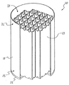
図1は、本発明で用いるのに適するキャニスター20を示している。キャニスター20は例示目的のみで図示してある。本発明は、特定の幾何学的配置、構造、又は寸法に限定されないが、放射性元素を輸送、貯蔵、又は保持するために用いられる任意のタイプの格納容器に対して適用可能である。したがって、本発明の範囲には、キャニスターを用いずにキャスクのキャビティ中に直接、使用済燃料(SNF)が充填されるキャスク態様も含まれる。
Detailed Description of the Drawings Figure 1 shows a
キャニスター20は、キャビティ21を形成する底部プレート22と円筒壁24とを含む。本明細書において、底部プレート22の最も近くにあるキャニスター20の末端25をキャニスター20の底部と呼び、底部プレート22から最も遠位にあるキャニスター20の末端26をキャニスター20の頂部と呼ぶ。キャニスター20のキャビティ21は、その中に配置されたハニカムグリッド23を有する。ハニカムグリッド23は、使用済核燃料(SNF)棒を受容するように適合された矩形ボックスを複数含む。キャニスター20は、更に、キャニスター20の外側からキャビティ21への密封可能な通路を提供する、キャニスター20の底部に又は底部近傍に配置された排水孔(図示せず)も含む。排水孔は、底部プレート22上に配置できる。更に、排水孔は、開けることができ、又は従来のプラグ、排水バルブ、もしくは溶接法を用いて密閉することができる。
The
図1に示してあるように、キャニスター20は空であり(すなわち、キャビティ21はハニカムグリッド23中に配置されるSNF棒を有していない)、キャニスター20の頂部26は開いている。キャニスター20を用いてSNF棒を輸送し貯蔵する場合、キャニスター20を輸送キャスク10の内側に配置する(図2)。キャニスター20は開放されていて空である。そのとき、キャニスター20の底部又は底部近傍に配置された排水孔は、閉じられ密閉されている。次に、開放輸送キャスク10及び開放キャニスター20を使用済燃料プール中に沈め、キャビティ21の残りの体積を水で満たす。次に、原子炉から取り出されるSNF棒を、使用済燃料プール中に沈め、キャニスター20のキャビティ21の内側に配置する。好ましくは、SNF棒の単一束をハニカムグリッド23の各々の矩形ボックスに配置する。SNF棒をキャビティ21に充填したら、キャニスターの蓋27(図2)を、キャニスター20の頂部26に固定して、SNF棒と、プール水とをキャビティ21中に密封する。キャニスターの蓋27は、開放したときに、キャニスター20の外部からキャビティ21中への通路を形成する複数の密封可能な蓋の孔28を有する。次に、クレーンによって輸送キャスク10(その中に充填され密封されたキャニスター20を有する)を使用済燃料プールから持ち上げ、(図2に示してある)中継場所に真っ直ぐに配置して、キャニスター20を乾燥貯蔵のために適切に用意することができる。
As shown in FIG. 1, the
図2をみると、中継場所において、キャニスター20(SNF棒及びプール水を含む)は輸送キャスク10内にある。キャニスター20及び輸送キャスク10は双方とも直立配置である。中継場所に適切に配置したら、キャニスター20の底部25又は底部近傍にある排水孔(図示せず)を開け、キャニスター20のキャビティ21に閉じ込められているバルク水を排水する。キャビティ21からバルク水を排水するが、極微量の液体の水及び水蒸気がキャビティ21の内部に残留するので、水分はキャビティ21中及びSNF棒上に残留している。しかしながら、キャニスター20を、永久的に密封し、長期乾燥貯蔵のための貯蔵キャスクに移動させる前に、確実に、キャニスター20の中に含まれているキャビティ21及びSNF棒を充分に乾燥させなければならない。容器内の蒸気圧(vP)が低いということは、存在している水分量が低レベルであるということなので、米国原子力規制委員会(N.R.C.)は、3トル(0.4kPa)又はそれより低い蒸気圧(vP)がキャビティ21内で得られるときに、充分な乾燥が達成されるとしている。
Looking at FIG. 2, at the transit location, the canister 20 (including SNF rods and pool water) is in the
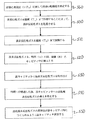
図3は、キャビティ21内で得られるvPを侵入的に測定する必要なく、許容可能なN.R.C.レベルまでキャビティ21を乾燥させることができる閉ループシステム300の一の態様を概略示している。図5は、本発明にしたがってシステム300を運転する方法の一態様に関する流れ図である。図6は、本発明にしたがってシステム300を運転する方法の第二の態様に関する流れ図である。
FIG. 3 shows an acceptable N.D. without the need to invasively measure the vP obtained in the
システム300をキャニスター20に接続して、閉ループシステムを形成する。しかしながら、本発明は、閉ループシステムが無くても実行可能である。システム300は、非反応性ガスリザーバ340、ガス冷却要素310、温度センサー320、ガス循環器330、補助ヒーター350、ガス流調節器360、及びガス分配器370を含む。図示してあるように、ガス冷却要素310は凝縮器370及び脱湿剤モジュール380を含む。これらの要素はすべて、非反応性ガスが外部環境中へと抜け出さずにシステム300を通って流れることができるように、流動的に接続されている。本明細書で説明するすべての流体接続は、ねじ込み接続、シール、リングクランプ、及び/又はガスケットを用いることによって、システム300の要素を流動的に接続する適するチュービング又はパイピングを用いることによって達成できる。パイピング及びチュービングは、金属製可とう性管又は金属製非可とう性管から構成できる。システム300の様々な要素に対してパイピング及びチュービングを流動的に接続する設計は、選択される装置の特定の設計構造及び選択されるパイピング又はチュービングの材料組成によって左右される。
好ましくは、非反応性ガスリザーバ340を用いてヘリウムガスを貯蔵する。ヘリウムガスは好ましい非反応性ガスであるが、システム300では、任意の非反応性ガスを用いることができ、それもまた本発明の範囲内である。例えば、非反応性ガスは、窒素、二酸化炭素、例えばメタンのような低級炭化水素ガス、又は限定するものではないがヘリウム、アルゴン、クリプトン及びキセノンを含む任意の不活性ガスであることができる。
Preferably, the
システム300中を流れるヘリウムガス流は、ガス循環器330によって生じる。ガス循環器330は、ガス循環器330を出るときにヘリウムガスの圧力を増大させることによって、システム300及びキャニスター20を通してヘリウムガスを循環させる。こうして、ガス循環器330を出るヘリウムガスは、システム300を反時計回りに押出される。システム300を流れるガス流の方向は、流体接続に関して示した矢印によって図示されている。
The helium gas stream flowing through the
ヘリウムリザーバ340はシステム300に対して充分なヘリウムガス源を提供する。ヘリウムリザーバ340は凝縮器370に対して流動的に接続されている。ヘリウムガスをシステム300中へ押出すと、ヘリウムリザーバ340内にあるヘリウムガスは凝縮器370中に流れる。ヘリウムガスが凝縮器370を通って流れると、ヘリウムガスは冷却される。この冷却により、ヘリウムガス中にトラップされている水分(すなわち、水蒸気)のいくらかがヘリウムガスから凝縮し、液体形態で凝縮器370中に集められる。液体の水は、排流管(図示せず)を経由して凝縮器370から取り出され、一方、部分的に乾燥したヘリウムガスは、分離流体接続を経由して脱湿剤モジュール380(凍結乾燥器としても知られている)中に流れる。次に、その部分乾燥ヘリウムガスは脱湿剤モジュール380中に流れ、そこで、管状熱交換器中を流れる冷媒流体によってヘリウムガスを凍結乾燥することによって、更にヘリウムガスが冷却される。部分乾燥ヘリウムガスのこの更なる温度低下により、追加の水分が生じ、ヘリウムガスから取り出される。そのようにして、脱湿剤モジュール380を出るヘリウムガスは、含水量が非常に低く(すなわち、蒸気圧が低い)、非常に乾燥している。脱湿剤モジュール380においてヘリウムガスから取り出される水分は、冷凍流体で冷却された熱交換器管によって直接凍結される。
The
脱湿剤モジュール380から流れ出てくるヘリウムガスの温度をモニターして、その温度を充分に低く保つことにより、ヘリウムガスを非常に乾燥した状態に確実にすることができる。脱湿剤モジュール380は、流出していくヘリウムガスを所望の低い温度Tcまで確実に冷却するように適合される。それは、温度センサー320を用いて流出していくヘリウムガスの温度をモニターすることによって達成される。温度センサー320は、電気接続325によって、脱湿剤モジュール380に対して使用可能に結合される。ユーザーインタフェース及び適切にプログラムされたプロセッサ(図示せず)を用いることによって、使用者によって、所望の温度TCが入力される。温度センサー320は、脱湿剤モジュール380を出ていくヘリウムガスの温度を繰返し測定する。流出ヘリウムガスの温度が入力した所望の温度TCと一致していない場合、適切な信号が脱湿剤モジュール380へと送られる。脱湿剤モジュール380は、送られた信号にしたがって、ヘリウムガスの冷却を強めたり弱めたりすることによって、信号に適切に応答する。この調節方法は、脱湿剤モジュールを出ていくヘリウムガスがTC又はそれより低い所望の温度に達する(且つ維持される)まで繰返され、図5及び図6それぞれの工程500及び600を完了する。以下で詳細に説明しているように、キャビティ21(図1)から充分量の水分を取り出して、キャビティ21において所望の蒸気圧(vPD)を達成できるように、流出していくヘリウムガスが充分に乾燥していることを保証するために、使用者によってTCは選択される。
By monitoring the temperature of the helium gas flowing out of the
乾燥ヘリウムガス(所望の温度TCとなっている)をガス循環器330中に流し、上記したように、乾燥ヘリウムガスの圧力を増加させて、乾燥ヘリウムガスを押出し、補助ヒーター350中に流し、システム300全体に循環させる。補助ヒーター350は、ガス循環器330の下流に流動的に接続されている。補助ヒーター350に入ると、乾燥ヘリウムガスは、所望の加熱温度(TH)まで過熱され、図5及び図6それぞれの工程510及び610を完了する。ヘリウムガスの温度をTHまで上昇させると、ヘリウムガスがキャビティ21に入るときに、キャビティ21から水分(SNF棒上の水分を含む)を取り出すことが容易になる。しかしながら、SNF棒は、しばしば、多量の熱を発生させるので、そのような場合には、補助ヒーター350の使用は不要であるかもしれない。補助ヒーター350により、使用可能に結合された温度センサー(図示せず)を用いて、補助ヒーター350から流出していく乾燥ヘリウムガスを、温度THに確実に維持する。この使用可能な接続に関する考察は、接続及び調節は脱湿剤モジュール380及び温度センサー320に関して用いられるものと同様であるので重複を避けるために省略される。
Dry helium gas (having the desired temperature T C ) is flowed into the
補助ヒーター350を出ると、乾燥ヘリウムガス(温度TH)はガス流調節器360中に流れる。ガス流調節要素360は、電気接続390によって、ガス循環器330に対して使用可能に結合される。本発明のいずれの方法が用いられるかに依存して、ガス流調節器360は、体積流量調節器又は質量流量調節器であることができる。
Upon exiting the
ガス流調節器360が体積流量調節器である場合、バルブは、一定の所望の体積流量(R)でヘリウムガスがバルブを通って流れるように適合される。所望の体積流量Rは、適切にプログラムされたプロセッサを有する結合されたユーザーインタフェース(図示せず)を介して使用者によって入力される。適切にプログラムされたプロセッサは、体積流量バルブへと信号を送り、所望の体積流量Rが達成されるようにバルブを調節する。この態様では、使用者は、所望の時間(t)もユーザーインタフェースに入力する。時間tが経過したら、適切にプログラムされたプロセッサは、ガス流調節器360に運転停止信号を送り、システム300中のヘリウムガスの流れを停止させる。このようにして、ガス流調節器360によって図5の工程520が容易に実行される。
If the
図5の工程520を容易にしうる別の方法は、質量流量調節器を用いる方法である。ガス流調節器360が質量流量調節器である場合、バルブは、質量流量調節器を通って流れる加熱された乾燥ヘリウムガスの質量を測定するように適合される。使用者は、体積流量値ではなく、所望の質量流量(R)及び所望の時間tを入力する。質量流量又は体積流量にかかわらず、所望の流量R及び時間tを使用者が決定する方法に関しては以下で詳細に説明する。
Another method that can facilitate step 520 of FIG. 5 is to use a mass flow controller. If the
別法として、使用者がユーザーインタフェースに数値Xを入力するようにガス流調節器360を適合させることができ、その際、値Xは、使用者がヘリウムガス流でキャビティ21の自由体積(VF)を入れ替えたい回数を表している。本明細書で使用するように、キャビティの自由体積(VF)とは、充填されたSNF棒とハニカムグリッド23とによって占有されていないキャビティの空間と規定される。VF値は、種々のキャニスターで異なり、キャニスターがSNF棒で完全に充填されているか否かに依存するが、任意の所定のキャニスターに関するVFは、キャビティ中に充填されるSNF棒の数及びサイズと、空のときのキャビティの体積とを知ることによって概算することができる。本特許において、充分なガスがキャビティ中に流されて自由体積VFを満たし、且つその自由体積をそれまで占有していたガスが置換されるとき、VFは入れ替えられる。例えば、VFが300立方フィート(8.50m 3 )であって、600立方フィート(17.0m 3 )の体積の乾燥ヘリウムガスがVF中に流れる場合、自由体積VFは2回入れ替えられる。したがって、Xは2.0である。システム300のこの態様では、VFが特定の回数入れ替えられて、キャビティ内において所望の蒸気圧vPDが達成されるように、使用者はXを選択する。使用者が所望のXを計算する方法については以下で詳細に説明する。所望のXは既知であると仮定すると、R及びtの代わりに、使用者は、ユーザーインタフェースにその値を入力する。適切にプログラムされたプロセッサはガス流調節器360(質量流量調節器又は体積流量調節器)と通信し、キャビティのVFを所望の回数X入れ替える体積の乾燥ヘリウムガスを供給して、図6の工程620を完了させる。所望の回数X回入れ替える体積の乾燥ヘリウムガスがキャビティ21に供給されると、適切にプログラムされたプロセッサは、ガス循環器330に対して運転停止の信号を送って、システム300を流れているヘリウムガス流を停止させる。
Alternatively, the
ガス流調節器360を出ると、乾燥ヘリウムガスはガス分配器370中に流れる。ガス分配器370は、キャビティ21に流動的に結合されていて、おそらくバルク水を排水するのに用いられるのと同じ排水バルブ(図示せず)を通して、キャニスター20の底部に又は底部近傍においてキャビティ21(図1)中に、加熱された乾燥ヘリウムガスを導入するように適合される。ガス分配器370は、キャビティ21のVF中に、加熱された乾燥ヘリウムガスを導入し、図5及び図6の工程520及び620それぞれを完了させる。キャビティ21の内部に入ると、水分を吸収することによって乾燥ヘリウムガスは湿潤する。乾燥ヘリウムガスによるこの水分吸収は、キャビティ21中に既に存在している水蒸気と混合することによって、またキャビティ21中及びSNF棒上に残留しているかもしれない液体の水を蒸発させることによって、起こる。乾燥ヘリウムガスを温度THまで過熱すると、乾燥ヘリウムガス中の加えられたエネルギーは、液体水の蒸発の開始に役立つ。乾燥ヘリウムガスをキャビティ21中に連続して導入すると、キャビティ21のVFが満たされる。VFが満たされると、乾燥ヘリウムガスの連続供給により、湿潤ヘリウムガスは、キャビティ21の頂部又は頂部近傍にある出口オリフィスからキャビティ21の外へと押出され、したがって図5及び図6の工程530及び630それぞれが完了する。出口オリフィスは、密封可能なキャニスターの蓋の孔28(図2)であることができる。キャビティ21から湿潤ヘリウムガスを取り出すと、キャビティ21における生成蒸気圧が低下する。湿潤ヘリウムガスがキャビティ21から流出すると、湿潤ヘリウムガスは、流体接続を通ってヘリウムリザーバ340へと運ばれる。かくして、湿潤ヘリウムガスは、システム300中を再循環して、連続キャニスター乾燥法を維持することができる。
Upon exiting
上記したように、加熱された乾燥ヘリウムガスを、時間t、流量Rでキャビティ21を通して循環させたら、キャビティ21中への加熱された乾燥ヘリウムガスの導入を停止し、図5の工程540を完了させる。別の態様では、VFをX回入れ替えて、図6の工程640を完了させるように、加熱された乾燥ヘリウムガスをキャビティ21を通して循環させて、加熱された乾燥ヘリウムガスのキャビティ21中への導入を停止する。この時点で、システム300は、キャニスター20と、キャビティ21中へのすべての開口(排水バルブ及び排水オリフィスを含む)とから切り離され、密封され、それにより、キャビティ21中に乾燥ヘリウムガスを閉じ込め、キャビティ21内に非反応性雰囲気をつくりだし、図5及び図6の工程550及び工程650のそれぞれを完了させる。
As described above, when the heated dry helium gas is circulated through the
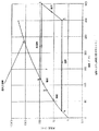
図4をみると、蒸気圧−温度線図によって、システム300を通って循環しているヘリウムガスの熱力学サイクルが図示されている。この線図でプロットされているのは、水に関する蒸気圧曲線である。蒸気圧曲線の上の部分では、水は液体状態であり、下の部分は、水蒸気状態である。曲線上の任意の点において、水蒸気と液体は平衡状態で同時に存在する。説明する目的のため、その熱力学グラフは、TCが21°F(−6.1℃)、THが300°F(149℃)及びキャビティ21における出発蒸気圧(vPS)が87トル(12kPa)であるようにシステム300が運転されていると仮定している。本明細書で用いているキャビティにおける出発蒸気圧vPSとは、キャビティからバルク水を排水した後ではあるが、乾燥ヘリウムガスをキャビティを通して循環させる前のキャビティにおける蒸気圧である。線図のポイント1で出発し、水蒸気で満たされている過熱されたヘリウムガスは、キャニスター20のキャビティ21から出て、凝縮器370に入る。凝縮器370の内部に入ると、過熱されたヘリウムガスはライン1−2に沿って、蒸気圧曲線と交わっている露点(すなわち、ポイント2)に達するまで冷却される。ライン2−3に沿って蒸気圧曲線の下方に向けて、凝縮器370において、露点未満の温度でヘリウムガスの冷却を継続して、ヘリウムガスから水蒸気を徐々に凝縮させる。2−3で凝縮される液体を分離し、凝縮器から取り出し、部分乾燥されたヘリウムガスは、脱湿剤モジュール380中に流れ、そこで凍結乾燥される。脱湿剤モジュール380では、ヘリウムガスを露点未満の温度まで更に冷却するが、TC(21°F(−6.1℃))が達成されるまで、ライン3−4に沿ってヘリウムガスから更に多くの水蒸気を凝縮させる。乾燥ヘリウムガスは、凝縮器モジュール380から出て、ライン4−5に沿って補助ヒーター350でTHまで過熱され、キャビティ21において液体の水を蒸発させるのに役立つ。SNF棒が充分に熱い場合、この過熱は、キャビティ21の内部で起こるので、補助ヒーター350の必要性が無くなる。キャビティ21の内部では、乾燥ヘリウムガスは、SNF棒から放出される熱によって更に加熱され、その加熱された乾燥ヘリウムガスは、蒸発している液体の水から生じる水蒸気を吸収するので、湿潤し、ライン5−1に沿って乾燥ヘリウムガスの蒸気圧が増加する。乾燥ヘリウムガスがキャビティ21を通って流れる限り、キャビティ21内の蒸気圧は低下し続ける。また、流出して行く湿潤ヘリウムガスの蒸気圧(ポイント5)は時間の経過と共に低下する。キャビティ21内の蒸気圧は、単調に減少し続けて、キャビティ21に入って行く加熱された乾燥非反応性ガスの蒸気圧に接近する。したがって、脱湿剤モジュール380に入って行くヘリウムガスの温度(TC)を充分に低くして、所望の蒸気圧(vPD)(この場合は3トル(0.4kPa)である)に比べて、等しいか又はそれより低い蒸気圧に相当するようにすることにより、前記の所望の蒸気圧(vPD)は、乾燥ヘリウムガスの充分量がキャビティ21を通って流れる限り、キャビティ21において達成できる。したがって、所望の乾燥度が蒸気圧に関して既知である限りは、システム300の使用者は、図4又は同様なグラフを用いてTCを計算して、あるレベルの乾燥度を達成できる。現在のN.R.C.規則が、乾燥度の一つの指標として、3トル(0.4kPa)又はそれより低い蒸気圧がキャビティ21で達成されることを要求していることから、vPDは3トル(0.4kPa)又はそれより低い。したがって、図5及び図6の工程560及び工程660のそれぞれを完了させる。かくして、所望の蒸気圧は21°F(−6.1℃)又はそれより低いTCに相当するということが図4から認められる。
Turning to FIG. 4, a vapor pressure-temperature diagram illustrates the thermodynamic cycle of helium gas circulating through the
vPD(3トル(0.4kPa))が既知であって、TCが計算されたら(21°F(−6.1℃))、次の工程において、キャビティ21内に存在する自由体積VFを決める。それは、キャビティ21に含まれているSNF棒のおおよその体積と、キャビティ21中に存在し得る任意の他の固体、例えばハニカムグリッド23の体積とを、キャビティ21の総体積から引くことによって求める。自由体積VFが決まったら、次に、システムの使用者は、補助ヒーター350によって乾燥ヘリウムガスが加熱される温度TH及びその加熱された乾燥ヘリウムガスがキャビティ21へと供給される流量Rを選択する。乾燥されるキャビティに関するVFの値と、TH及びRに関して選択される値とにしたがって、キャビティが3トル(0.4kPa)の所望の蒸気圧vPDに達する前に、加熱された乾燥ヘリウムガスを、時間tの間、キャビティに通って流さなければならない。キャビティ21内の条件をシミュレートし、システム300の変数に関して仮定値を設定することにより、データの適切なグラフを読み取って、時間tを、変数の任意の所定のセットに関して決定できる。
Once vP D (3 Torr (0.4 kPa) ) is known and TC is calculated (21 ° F. (−6.1 ° C.) ), the free volume V present in the
図7をみると、シミュレートされた条件の所定のセットに関して、キャビティを通って流れるガス流の時間に対してキャビティ中において得られた蒸気圧をグラフ化しているデータグラフが図示してある。この時間−蒸気圧グラフを作成する際、次の条件を仮定又は選択した:(1)vPDは3トル(0.4kPa)(図4から、21°F(−6.1℃)のTCと関連がある);(2)VFは300立方フィート(8.50m 3 );(3)THは300°F(149℃)(一立方フィートあたり約0.032ポンド(0.513kg/m 3 )のヘリウム密度ρと関連がある);(4)Rは一分あたり78.125立方フィート(2.2123m 3 );(5)キャビティ圧力(PC)は一平方インチあたり50ポンド(3.4kPa);及び(6)キャビティ内の出発蒸気圧vPSは87トル(12kPa)である。データプロットから分かるように、乾燥ヘリウムガスを長時間キャビティ中に流すと、キャビティ内で得られる蒸気圧は低下する。そのデータをプロットすることによって、約22.5分の時間tにおいて、キャビティ内で得られる蒸気圧は、3トル(0.4kPa)のvPDに等しいことが分かる。時間tを決める際、温度TCが脱湿剤モジュールを出ていくヘリウムガスに関して温度TCが達成された後に、時間を計測し始める。図7の条件は、ただ例示目的のみで選択した。キャビティ内の始動条件の任意の所定のセット及び使用者によって選択された任意の変数に関して、同様なグラフをシミュレートすることができる。したがって、任意の所望のvPDを達成するのに要する時間は、キャビティ内の蒸気圧を直接(侵入的に)測定する必要なく、条件の任意の所定のセットに関して概算できる。適切なグラフは、適切にプログラムされたコンピュータによるシミュレーションによって又は実際の実験データをグラフ化することによって作成できる。
Turning to FIG. 7, a data graph is shown that graphs the vapor pressure obtained in the cavity against the time of gas flow flowing through the cavity for a given set of simulated conditions. The time - when creating vapor pressure graph, assuming the following conditions or selected: (1) vP D is from 3 torr (0.4 kPa) (Fig. 4, T of 21 ° F (-6.1 ℃) C to be related); (2) V F is 300 cubic feet (8.50m 3); (3) T H is 300 ° F (149 ℃) (about 0.032 lbs per one cubic foot (0.513Kg / m 3) is associated with the helium density ρ of); (4) R is 78.125 cubic feet per minute (2.2123m 3); (5) a
別法として、Rは質量流量であるように選択できる。質量流量は、単にガス流の密度が分かれば、体積流量と容易に置き換えることができる。ガスの質量流量は、体積流量にガス密度を掛けた値に等しい。例えば、上で選択した78.125立方フィート(2.2123m 3 )/分の体積流量Rは、ヘリウムの密度が約0.032ポンド/立方フィート(0.513kg/m 3 )であるので、2.5ポンド(1.1kg)/分の質量流量に相当する。したがって、所定の質量流量に関して、図7と同様なデータプロットをシミュレートできる。 Alternatively, R can be selected to be a mass flow rate. Mass flow rate can be easily replaced with volume flow rate simply by knowing the density of the gas flow. The mass flow rate of the gas is equal to the volume flow rate multiplied by the gas density. For example, the volume flow rate R selected above of 78.125 cubic feet (2.2123 m 3 ) / min is 2 because the density of helium is about 0.032 pounds / cubic foot (0.513 kg / m 3 ). Corresponds to a mass flow of .5 pounds (1.1 kg) / min. Therefore, a data plot similar to FIG. 7 can be simulated for a given mass flow rate.
更に、任意の単一の変数を、残りの変数を設定することによって、計算できる。例えば、ある乾燥時間tが望ましい場合、得られる蒸気圧対ガス流量Rをプロットしているグラフを作成でき、その際、時間tは一定に保たれ、流量Rは変えられる。したがって、本発明は、任意の特定の変数が一定に保たれている状態に限定されない。 In addition, any single variable can be calculated by setting the remaining variables. For example, if a certain drying time t is desired, a graph plotting the resulting vapor pressure versus gas flow rate R can be created, with the time t being kept constant and the flow rate R being varied. Thus, the present invention is not limited to the situation where any particular variable is kept constant.
図8をみると、シミュレートされた条件の所定のセットに関して、ガスによる自由体積(VC)時間の入れ替え回数(X)に対するキャビティで得られる蒸気圧をグラフ化しているデータグラフが図示してある。この入れ替え回数−蒸気圧グラフを作成する際、次の条件を仮定又は選択した:(1)vPDは3トル(図4から、21°F(−6.1℃)のTCと関連がある);(2)VFは300立方フィート(8.50m 3 );(3)THは300°F(149℃)(一立方フィートあたり約0.032ポンド(0.513kg/m 3 )のヘリウム密度ρと関連がある);(4)キャビティ圧力(PC)は一平方インチあたり50ポンド(3.4kPa);及び(5)キャビティ内の出発蒸気圧vPSは87トル(12kPa)である。任意の所定のキャニスターに関してシステム300を連続運転するとき、キャビティの自由体積VF中に流れるガスの総体積(Vtot)は増加する。Xは、VtotをVFで割った値に等しいので、ヘリウムガスが流れ続けると、Xも増加する。Xが増加すると、得られる蒸気圧は、蒸気圧プロット線に沿って低下することが、図8から分かる。このデータプロット線から、キャビティ内部で得られる蒸気圧が、3トル(0.4kPa)という所望の蒸気圧vPDに等しいか又はそれより低いときのXを求めることができる。
Referring to FIG. 8, a data graph illustrating the vapor pressure obtained in the cavity against the number of replacements (X) of free volume (V C ) time by gas for a given set of simulated conditions is illustrated. is there. The replacement times - when creating vapor pressure graph, the following conditions assumed or selected: (1) vP D is from 3 torr (4, associated with T C of 21 ° F (-6.1 ℃) there); (2) V F is 300 cubic feet (8.50m 3); (3) T H is 300 ° F (149 ℃) (about 0.032 lbs per one cubic foot (0.513kg / m 3) it is associated with the helium density ρ of); (4) a
図9をみると、5.86に等しいか又はそれより大きいXが得られるように、充分な体積の加熱された乾燥ヘリウムガスをキャビティを通して流すとき、キャビティ内において、所望の蒸気圧(vPD)3トル(0.4kPa)が達成されることが分かる。したがって、5.86以下のXが達成されるようにシステム300をプログラミングすることによって、キャビティ内部を直接(侵入的に)測定する必要なく、3トル(0.4kPa)という所望の蒸気圧vPDがキャビティ中で達成されることを保証することができる。図8及び図9の条件は、ただ例示目的のみで選択した。本発明の精神から逸脱せずに、キャビティ内の始動条件の任意の所定のセットに関して、また使用者によって所望された又は選択された任意の変数に関して同様なグラフをシミュレート(又は実際の実験データを用いてプロット)することができる。
Referring to FIG. 9, when a sufficient volume of heated dry helium gas is flowed through the cavity to obtain an X equal to or greater than 5.86, the desired vapor pressure (vP D It can be seen that 3 Torr (0.4 kPa) is achieved. Thus, by programming the
Claims (35)
水の蒸気圧曲線を用いて、所望の蒸気圧(vP D )以下の蒸気圧に相当する温度(T C )を決定し、
非反応性ガスを前記温度(TC)まで冷却することによって該非反応性ガスを乾燥させ;
時間(t)の間、流量(R)で該乾燥非反応性ガスを該キャビティ中に導入し;そして、
該キャビティから湿潤非反応性ガスを取り出すことを含み、
その際、時間tの後に、該キャビティ中において所望の蒸気圧(vPD)が達成されるように、前記キャビティの自由体積(V F )、出発蒸気圧(vP S )及びキャビティ圧力(P C )に基づいてT C 及びRが調節される、前記方法。 A method of drying a cavity filled with a radioactive element, the filled cavity having a free volume (V F ), a starting vapor pressure (vP S ) and a cavity pressure (P C ), :
Using vapor pressure curve of water, to determine the temperature (T C) corresponding to a desired vapor pressure (vP D) vapor pressure below,
Dry the non-reactive gas by cooling the non-reactive gas to said temperature (T C);
Introducing the dry non-reactive gas into the cavity at a flow rate (R) for a time (t); and
Removing wet non-reactive gas from the cavity;
In so doing, after time t, the free volume (V F ), the starting vapor pressure (vP S ) and the cavity pressure (P C ) of the cavity are achieved so that the desired vapor pressure (vP D ) is achieved in the cavity. ), Wherein TC and R are adjusted .
0立方フィート(8.50m3)であり、PCが一平方インチあたり50ポンド(3.4kPa)であり、そしてvPSが87トル(12kPa)であり;Rが一分あたり2.5ポンド(1.1kg)に設定された質量流量であり、THが300°F(149℃)に設定され、そしてTCが21°F(−6.1℃)又はそれより低く設定され;時間tが22.5分である、請求項3記載の方法。 A non-reactive gas is helium, when vP D is 3 Torr (0.4 kPa), V F is 30
0 is cubic feet (8.50m 3), P C is 50 pounds per one square inch (3.4 kPa), and vP S is located at 87 torr (12 kPa); R 2.5 pounds per minute a mass flow rate that is set to (1.1kg), T H is set to 300 ° F (149 ℃), and T C is 21 ° F (-6.1 ℃) or set it lower than; time 4. A method according to claim 3, wherein t is 22.5 minutes.
該キャビティを密封することによって、該キャビティ内において乾燥非反応性ガスの雰囲気を形成させ、その際、該キャビティがvPD又はそれより低い蒸気圧を有することを更に含む、請求項1記載の方法。 Stop the introduction of dry non-reactive gas into the cavity after time t has passed; and
By sealing the cavity to form a atmosphere of dry non-reactive gas within the cavity, whereby, further comprising The method of claim 1, wherein that the cavity has a vP D or lower vapor pressure than that .
水の蒸気圧曲線を用いて、所望の蒸気圧(vP D )以下の蒸気圧に相当する温度(T C )を決定し、
非反応性ガスを前記温度(TC)まで冷却することによって該非反応性ガスを乾燥させ;
該キャビティの自由体積VFがX回入れ替わるように、該乾燥非反応性ガスを該キャビティ中に導入し;そして、
該キャビティから湿潤非反応性ガスを取り出すことを含み
その際、該キャビティ中において該所望の蒸気圧(vPD)が達成されるように、前記キャビティの自由体積(V F )、出発蒸気圧(vP S )及びキャビティ圧力(P C )に基づいてT C 及びRが調節される、前記方法。 A method of drying a cavity filled with a radioactive element, the filled cavity having a free volume (V F ), a starting vapor pressure (vP S ) and a cavity pressure (P C ), :
Using vapor pressure curve of water, to determine the temperature (T C) corresponding to a desired vapor pressure (vP D) vapor pressure below,
Dry the non-reactive gas by cooling the non-reactive gas to said temperature (T C);
Introducing the dry non-reactive gas into the cavity such that the free volume V F of the cavity is replaced X times; and
At that time it comprises retrieving the wet non-reactive gas from the cavity, so that said desired vapor pressure during the cavity (vP D) is achieved, the free volume (V F) of the cavity, starting vapor pressure ( The method , wherein TC and R are adjusted based on vP S ) and cavity pressure (P C ) .
該キャビティを密封することによって、該キャビティ内において乾燥非反応性ガスの雰囲気を形成させ、該キャビティがvPD又はそれより低い蒸気圧を有することを更に含む、請求項12記載の方法。 After replacing the free volume V F of the cavity X times, stopping the introduction of dry non-reactive gas into the cavity; and
By sealing the cavity to form a atmosphere of dry non-reactive gas within the cavity, further comprising the method of claim 12, wherein that said cavity has a vP D or lower vapor pressure than that.
該システムに対して非反応性ガスを供給するように適合させた非反応性ガス源;
水の蒸気圧曲線を用いて決定される、所望の蒸気圧(vP D )以下の蒸気圧に相当する温度(T C )まで非反応性ガスを冷却することによって該非反応性ガスを乾燥させる手段;
該乾燥非反応性ガスを該キャビティに流す手段であって、該乾燥非反応性ガスを該キャビティに流量Rで時間(t)の間導入するように適合させた、該流動手段;
湿潤非反応性ガスを該キャビティから取り出す手段を含み;
その際、該非反応性ガス源、該冷却手段、該流動手段、該取り出し手段、及び該キャビティが流動的に結合されていて;
時間tで該キャビティ中において所望の蒸気圧(vPD)が達成されるように、前記キャビティの自由体積(V F )、出発蒸気圧(vP S )及びキャビティ圧力(P C )に基づいてT C 及びRが調節される、前記システム。 A system for drying a cavity filled with a radioactive element, wherein the filled cavity has a free volume (V F ), a starting vapor pressure (vP S ) and a cavity pressure (P C ), :
A non-reactive gas source adapted to supply a non-reactive gas to the system;
Means for drying the non-reactive gas by cooling the non-reactive gas to a temperature (T C ) determined using a water vapor pressure curve and corresponding to a vapor pressure below the desired vapor pressure (vP D ) ;
Means for flowing the dry non-reactive gas into the cavity, the flow means adapted to introduce the dry non-reactive gas into the cavity at a flow rate R for a time (t);
Means for removing wet non-reactive gas from the cavity;
Wherein the non-reactive gas source, the cooling means, the flow means, the removal means, and the cavity are fluidly coupled;
Based on the free volume (V F ) of the cavity , the starting vapor pressure (vP S ) and the cavity pressure (P C ), so that the desired vapor pressure (vP D ) is achieved in the cavity at time t. The system , wherein C and R are adjusted .
34. A system according to any of claims 21 to 33, wherein the cavities are not exposed to reduced pressure.
Applications Claiming Priority (2)
| Application Number | Priority Date | Filing Date | Title |
|---|---|---|---|
| US10/318,657 US7096600B2 (en) | 2002-12-13 | 2002-12-13 | Forced gas flow canister dehydration |
| US10/318657 | 2002-12-13 |
Publications (3)
| Publication Number | Publication Date |
|---|---|
| JP2004219408A JP2004219408A (en) | 2004-08-05 |
| JP2004219408A5 JP2004219408A5 (en) | 2006-11-16 |
| JP4800567B2 true JP4800567B2 (en) | 2011-10-26 |
Family
ID=32325973
Family Applications (1)
| Application Number | Title | Priority Date | Filing Date |
|---|---|---|---|
| JP2003414240A Expired - Lifetime JP4800567B2 (en) | 2002-12-13 | 2003-12-12 | Forced gas flow canister dewatering |
Country Status (7)
| Country | Link |
|---|---|
| US (3) | US7096600B2 (en) |
| EP (1) | EP1429344B1 (en) |
| JP (1) | JP4800567B2 (en) |
| KR (1) | KR100840809B1 (en) |
| AT (1) | ATE496375T1 (en) |
| DE (1) | DE60335778D1 (en) |
| ES (1) | ES2362495T3 (en) |
Families Citing this family (35)
| Publication number | Priority date | Publication date | Assignee | Title |
|---|---|---|---|---|
| KR100556503B1 (en) * | 2002-11-26 | 2006-03-03 | 엘지전자 주식회사 | Control Method of Drying Time for Dryer |
| US7096600B2 (en) * | 2002-12-13 | 2006-08-29 | Holtec International, Inc. | Forced gas flow canister dehydration |
| US20050102851A1 (en) | 2003-11-15 | 2005-05-19 | Tianqing He | Device and methods for rapid drying of porous materials |
| US7707741B2 (en) * | 2005-06-06 | 2010-05-04 | Holtec International, Inc. | Method and apparatus for dehydrating high level waste based on dew point temperature measurements |
| JP4880271B2 (en) * | 2005-09-21 | 2012-02-22 | 株式会社神戸製鋼所 | Radioactive waste disposal method and radioactive waste burying disposal container structure |
| US7994380B2 (en) * | 2006-10-11 | 2011-08-09 | Holtec International, Inc. | Apparatus for transporting and/or storing radioactive materials having a jacket adapted to facilitate thermosiphon fluid flow |
| DE102007013092A1 (en) * | 2007-03-14 | 2008-09-18 | Testo Ag | Apparatus and method for drying fluids circulated in closed circuits |
| ES2673615T3 (en) | 2007-12-21 | 2018-06-25 | Holtec International, Inc. | Method for preparing a container loaded with wet radioactive elements for dry storage |
| JP4838788B2 (en) * | 2007-12-25 | 2011-12-14 | 株式会社神戸製鋼所 | A method for measuring residual moisture in a drying process of radioactive solid waste and a drying treatment apparatus for radioactive solid waste provided with a residual moisture measuring device |
| US9001958B2 (en) | 2010-04-21 | 2015-04-07 | Holtec International, Inc. | System and method for reclaiming energy from heat emanating from spent nuclear fuel |
| US11569001B2 (en) | 2008-04-29 | 2023-01-31 | Holtec International | Autonomous self-powered system for removing thermal energy from pools of liquid heated by radioactive materials |
| US8404099B2 (en) * | 2008-09-19 | 2013-03-26 | David E. Fowler | Electrolysis of spent fuel pool water for hydrogen generation |
| EP2430635A4 (en) * | 2009-05-06 | 2013-12-25 | Holtec International Inc | Apparatus for storing and/or transporting high level radioactive waste, and method for manufacturing the same |
| JP2013503353A (en) * | 2009-08-31 | 2013-01-31 | トランスニュークリア インコーポレイテッド | Rack system and assembly for fuel storage |
| US8995604B2 (en) | 2009-11-05 | 2015-03-31 | Holtec International, Inc. | System, method and apparatus for providing additional radiation shielding to high level radioactive materials |
| US10811154B2 (en) | 2010-08-12 | 2020-10-20 | Holtec International | Container for radioactive waste |
| US9514853B2 (en) | 2010-08-12 | 2016-12-06 | Holtec International | System for storing high level radioactive waste |
| US8905259B2 (en) | 2010-08-12 | 2014-12-09 | Holtec International, Inc. | Ventilated system for storing high level radioactive waste |
| US11373774B2 (en) | 2010-08-12 | 2022-06-28 | Holtec International | Ventilated transfer cask |
| US11887744B2 (en) | 2011-08-12 | 2024-01-30 | Holtec International | Container for radioactive waste |
| FR2985365B1 (en) * | 2011-12-29 | 2014-01-24 | Tn Int | THERMAL DRIVER FOR SIDE BODY FOR PACKAGING TRANSPORT AND / OR STORAGE OF RADIOACTIVE MATERIALS |
| DE102012212006A1 (en) * | 2012-03-02 | 2013-09-05 | Areva Gmbh | Container for gas-tight encapsulation of fuel rod or fuel rod portion, comprises hollow cylindrical container portion that is closed at free ends in fluid-tight manner by closure stopper, where closure stopper is provided with channel |
| WO2013127894A1 (en) | 2012-03-02 | 2013-09-06 | Areva Gmbh | Method and device for encapsulating a fuel rod or a fuel rod section for temporary storage |
| KR101333066B1 (en) * | 2012-03-30 | 2013-11-27 | 한국원자력환경공단 | Transport or storage concrete cask for spent nuclear fuel |
| US9831005B2 (en) | 2012-04-18 | 2017-11-28 | Holtec International, Inc. | System and method of storing and/or transferring high level radioactive waste |
| US9136027B2 (en) * | 2013-07-20 | 2015-09-15 | Institute Of Nuclear Energy Research | Method of drying high-level radioactive wastes and device thereof |
| EP3134900B1 (en) | 2014-04-24 | 2019-10-23 | Holtec International | Storage system for nuclear fuel |
| CN106482451B (en) * | 2016-09-23 | 2022-05-27 | 广东核电合营有限公司 | Vacuum drying and helium filling device for spent fuel storage and transportation container |
| KR101959790B1 (en) * | 2018-11-19 | 2019-03-19 | 세안기술 주식회사 | A suitability evaluation method of drying using gas mass spectrometry for the drystorage of spent nuclear fuel and apparatus thereof |
| KR102021889B1 (en) * | 2019-03-05 | 2019-09-17 | 세안기술 주식회사 | A dryer for transport and storage of the spent nuclear fuel with the dry adeguacy by gas spectrometry and control method thereof |
| JP7181150B2 (en) * | 2019-04-19 | 2022-11-30 | 日立Geニュークリア・エナジー株式会社 | Drying equipment and processing system |
| FR3110278B1 (en) | 2020-05-18 | 2023-10-06 | Tn Int | detachable heating device from a lateral packaging body for radioactive material, comprising a jacket filled with heat transfer liquid |
| KR102248412B1 (en) * | 2020-09-28 | 2021-05-06 | 세안기술 주식회사 | A drier for canister of spent nuclear fuel |
| CN112361948B (en) * | 2020-10-29 | 2022-02-22 | 中国核动力研究设计院 | Heating device for simulating different temperature control of fuel rod-spent pool |
| US20230079635A1 (en) * | 2021-09-16 | 2023-03-16 | Benjamin BRITTON | Extraction freeze drying system with removable condenser |
Family Cites Families (90)
| Publication number | Priority date | Publication date | Assignee | Title |
|---|---|---|---|---|
| US2861033A (en) * | 1956-04-26 | 1958-11-18 | Treshow Michael | Horizontal boiling reactor system |
| GB827085A (en) * | 1956-06-29 | 1960-02-03 | Atomic Energy Commission | Nuclear reactors |
| US2873242A (en) * | 1956-06-29 | 1959-02-10 | Treshow Michael | Neutronic reactor system |
| NL238889A (en) * | 1958-05-05 | |||
| NL242148A (en) * | 1958-08-08 | |||
| US3105026A (en) * | 1958-08-26 | 1963-09-24 | James J Dickson | Fuel elment for nuclear reactors |
| US3158543A (en) * | 1959-08-14 | 1964-11-24 | Sherman Jerome | Fuel assembly support system for nuclear reactor |
| US3060111A (en) * | 1959-08-14 | 1962-10-23 | Sherman Jerome | Nuclear reactor |
| US3228848A (en) * | 1959-10-29 | 1966-01-11 | Socony Mobil Oil Co Inc | Method and contact material for chemical conversion in presence of nuclear fission fragments |
| GB1089342A (en) * | 1964-05-09 | 1967-11-01 | English Electric Co Ltd | Nuclear reactor reactivity control arrangements |
| US3483380A (en) * | 1965-04-09 | 1969-12-09 | Gulf General Atomic Inc | Shielded cask for radioactive material |
| US3278387A (en) * | 1965-11-29 | 1966-10-11 | Leonard E Mcneese | Fuel recycle system in a molten salt reactor |
| GB1169214A (en) * | 1966-04-01 | 1969-10-29 | English Electric Co Ltd | Nuclear Reactor Fuel Handling Arrangements |
| SE324191B (en) * | 1968-12-02 | 1970-05-25 | Asea Ab | |
| US3666616A (en) * | 1970-01-07 | 1972-05-30 | Babcock & Wilcox Co | Vapor suppressing means for a nuclear reactor |
| US3812008A (en) * | 1970-05-20 | 1974-05-21 | E Fryer | Seal ring for nuclear reactors |
| US3752738A (en) * | 1970-07-06 | 1973-08-14 | Nuclear Services Corp | Nuclear reactor plant and multiple purpose shielding system therefor |
| US4210614A (en) * | 1970-08-05 | 1980-07-01 | Nucledyne Engineering Corp. | Passive containment system |
| US4050983A (en) * | 1970-08-05 | 1977-09-27 | Nucledyne Engineering Corporation | Passive containment system |
| US3865688A (en) * | 1970-08-05 | 1975-02-11 | Frank W Kleimola | Passive containment system |
| US3732427A (en) * | 1971-03-17 | 1973-05-08 | A Trudeau | Integrated transport system for nuclear fuel assemblies |
| US3944646A (en) * | 1972-05-11 | 1976-03-16 | Union Carbide Corporation | Radioactive krypton gas separation |
| US3950152A (en) * | 1972-12-01 | 1976-04-13 | Rockwell International Corporation | Filter vapor trap |
| US4053067A (en) * | 1973-06-25 | 1977-10-11 | Westinghouse Electric Corporation | Fuel transfer system for a nuclear reactor |
| US3878040A (en) * | 1973-09-20 | 1975-04-15 | Combustion Eng | Failed fuel detector |
| US4182652A (en) * | 1974-12-17 | 1980-01-08 | Puechl Karl H | Nuclear fuel element, core for nuclear reactor, nuclear fuel material |
| US4055508A (en) * | 1976-08-06 | 1977-10-25 | Automation Industries, Inc. | Cask handling method and apparatus |
| US4209420A (en) * | 1976-12-21 | 1980-06-24 | Asea Aktiebolag | Method of containing spent nuclear fuel or high-level nuclear fuel waste |
| US4225467A (en) * | 1977-11-25 | 1980-09-30 | The Carborundum Company | Neutron absorbing article and method for manufacture of such article |
| US4287145A (en) * | 1977-11-25 | 1981-09-01 | Kennecott Corporation | Method for manufacturing neutron absorbing article |
| US4257912A (en) * | 1978-06-12 | 1981-03-24 | Westinghouse Electric Corp. | Concrete encapsulation for spent nuclear fuel storage |
| FR2461337A1 (en) * | 1979-07-06 | 1981-01-30 | Centre Etd Energie Nucleaire | METHOD FOR LOCATING A FUYARD BAR IN A NUCLEAR FUEL ASSEMBLY |
| US4336460A (en) * | 1979-07-25 | 1982-06-22 | Nuclear Assurance Corp. | Spent fuel cask |
| GB2116900B (en) * | 1982-02-18 | 1985-06-05 | Nat Nuclear Corp Ltd | Dry storage of irradiated nuclear fuel |
| DE3226986C2 (en) * | 1982-07-19 | 1984-08-30 | Kraftwerk Union AG, 4330 Mülheim | Process for encapsulating radioactive components and equipment for carrying out this process |
| DE3320071A1 (en) * | 1983-06-03 | 1984-12-06 | Siemens AG, 1000 Berlin und 8000 München | ARRANGEMENT FOR RECEIVING BURNED NUCLEAR REACTOR FUEL BARS AND METHOD FOR HANDLING THE SAME |
| US4781883A (en) * | 1984-09-04 | 1988-11-01 | Westinghouse Electric Corp. | Spent fuel storage cask having continuous grid basket assembly |
| DE3505242A1 (en) * | 1985-02-15 | 1986-08-21 | Deutsche Gesellschaft für Wiederaufarbeitung von Kernbrennstoffen mbH, 3000 Hannover | METHOD AND DEVICE FOR SEPARATING FUEL RODS OF A FUEL ELEMENT |
| US4952339A (en) * | 1985-03-22 | 1990-08-28 | Nuclear Packaging, Inc. | Dewatering nuclear wastes |
| US4709579A (en) * | 1985-08-16 | 1987-12-01 | Westinghouse Electric Corp. | Measurement of moisture content |
| US4723359A (en) * | 1986-06-13 | 1988-02-09 | Westinghouse Electric Corp. | Spent fuel rod horizontal consolidation system and method |
| US4828760A (en) | 1987-03-09 | 1989-05-09 | Rockwell International Corporation | Method of cleaning a spent fuel assembly |
| US4828700A (en) * | 1987-07-20 | 1989-05-09 | The Dow Chemical Company | Rejection enhancing coatings for reverse osmosis membranes |
| US5149491A (en) * | 1990-07-10 | 1992-09-22 | General Electric Company | Seed and blanket fuel arrangement for dual-phase nuclear reactors |
| US5063299A (en) * | 1990-07-18 | 1991-11-05 | Westinghouse Electric Corp. | Low cost, minimum weight fuel assembly storage cask and method of construction thereof |
| US5098644A (en) * | 1990-08-22 | 1992-03-24 | Nuclear Assurance Corporation | Apparatus for consolidation of spent nuclear fuel rods |
| US5194216A (en) * | 1990-08-22 | 1993-03-16 | Nuclear Assurance Corporation | Guide plate for locating rods in an array |
| US5152958A (en) * | 1991-01-22 | 1992-10-06 | U.S. Tool & Die, Inc. | Spent nuclear fuel storage bridge |
| US5790617A (en) * | 1992-03-26 | 1998-08-04 | Siemens Power Corporation | Method and apparatus for detection of failed fuel rods by use of acoustic energy frequency attenuation |
| US5253597A (en) * | 1992-06-18 | 1993-10-19 | Chemical Waste Management, Inc. | Process for separating organic contaminants from contaminated soils and sludges |
| US5319686A (en) * | 1993-07-30 | 1994-06-07 | Newport News Shipbuilding And Dry Dock Company | Dry transfer of spent nuclear rods for transporation |
| JPH07218686A (en) * | 1994-02-04 | 1995-08-18 | Ishikawajima Harima Heavy Ind Co Ltd | Method and device for loading spent fuel assembly to canister |
| WO1996010830A1 (en) * | 1994-10-04 | 1996-04-11 | Siemens Aktiengesellschaft | Drying station for liquid or damp waste |
| US5633904A (en) * | 1994-11-09 | 1997-05-27 | Newport News Shipbuilding And Dry Dock Company | Spent nuclear fuel (SNF) dry transfer system |
| US5646971A (en) * | 1994-11-16 | 1997-07-08 | Hi-Temp Containers Inc. | Method and apparatus for the underwater loading of nuclear materials into concrete containers employing heat removal systems |
| US5677938A (en) * | 1995-03-13 | 1997-10-14 | Peco Energy Company | Method for fueling and operating a nuclear reactor core |
| US5793636A (en) * | 1995-04-28 | 1998-08-11 | Westinghouse Electric Corporation | Integrated fuel management system |
| US5848111A (en) * | 1995-08-07 | 1998-12-08 | Advanced Container Int'l, Inc. | Spent nuclear fuel container |
| JPH0980196A (en) * | 1995-09-11 | 1997-03-28 | Ishikawajima Harima Heavy Ind Co Ltd | Method and container for housing spent fuel |
| US5995573A (en) * | 1996-09-18 | 1999-11-30 | Murray, Jr.; Holt A. | Dry storage arrangement for spent nuclear fuel containers |
| US5771265A (en) * | 1996-12-19 | 1998-06-23 | Montazer; Parviz | Method and apparatus for generating electrical energy from nuclear waste while enhancing safety |
| DE19701549C2 (en) * | 1997-01-17 | 2000-08-03 | Gnb Gmbh | Method for recooling a container loaded with spent fuel elements for the transport and / or storage of the fuel elements |
| US6372157B1 (en) | 1997-03-24 | 2002-04-16 | The United States Of America As Represented By The United States Department Of Energy | Radiation shielding materials and containers incorporating same |
| US5898747A (en) * | 1997-05-19 | 1999-04-27 | Singh; Krishna P. | Apparatus suitable for transporting and storing nuclear fuel rods and methods for using the apparatus |
| US20020025016A1 (en) * | 1997-06-05 | 2002-02-28 | Francesco Venneri | Accelerator-driven transmutation of spent fuel elements |
| US6680994B2 (en) * | 1997-09-19 | 2004-01-20 | British Nuclear Fuels Plc | Monitoring the contents of a container by ultrasonic means |
| DE19814791C1 (en) * | 1998-04-02 | 1999-11-25 | Gnb Gmbh | Drying of transport- and/or storage-containers holding radioactive waste |
| JPH11337693A (en) | 1998-05-29 | 1999-12-10 | Hitachi Zosen Corp | Vacuum drying device of spent nuclear fuel containment vessel |
| US6327321B1 (en) * | 1998-11-20 | 2001-12-04 | Framatome Anp, Inc. | Borated aluminum rodlets for use in spent nuclear fuel assemblies |
| BR0009655A (en) * | 1999-04-08 | 2002-03-26 | Electric Power Res Inst | Apparatus and process for cleaning an irradiated nuclear fuel assembly |
| WO2001024199A1 (en) * | 1999-09-29 | 2001-04-05 | Hitachi, Ltd. | Method of carrying equipment out of nuclear power plant |
| JP3297412B2 (en) * | 1999-11-01 | 2002-07-02 | 三菱重工業株式会社 | Neutron absorption rod, insertion device, cask, and method for transporting and storing spent nuclear fuel assemblies |
| GB2370037B (en) * | 1999-12-17 | 2004-06-09 | Warner Lambert Res & Dev Ie | A process for removing trace solvent from a material |
| JP3207841B1 (en) * | 2000-07-12 | 2001-09-10 | 三菱重工業株式会社 | Aluminum composite powder and method for producing the same, aluminum composite material, spent fuel storage member and method for producing the same |
| JP2002156488A (en) * | 2000-11-21 | 2002-05-31 | Hitachi Ltd | Draying method for vessel and dryer |
| JP2002243888A (en) * | 2001-02-14 | 2002-08-28 | Mitsubishi Heavy Ind Ltd | Sealing method for radioactive material and cooling device |
| JP3519694B2 (en) * | 2001-03-14 | 2004-04-19 | 三菱重工業株式会社 | Metal closed containers and methods for drying metal closed containers |
| US6597755B2 (en) * | 2001-07-06 | 2003-07-22 | Leroy Paul Seefeld | Apparatus and method for installing nuclear reactors |
| US6658078B2 (en) * | 2001-07-23 | 2003-12-02 | Tokyo Electric Power Co. | MOX nuclear fuel assembly employable for a thermal neutron nuclear reactor |
| US6950152B2 (en) * | 2001-10-18 | 2005-09-27 | Alps Electric Co., Ltd. | Television tuner which has leveled a gain deviation in the same band |
| US6865688B2 (en) * | 2001-11-29 | 2005-03-08 | International Business Machines Corporation | Logical partition management apparatus and method for handling system reset interrupts |
| US20050031066A1 (en) * | 2001-12-19 | 2005-02-10 | Hitachi, Ltd. | Method for carrying out the equipment of nuclear power plant |
| US20030198313A1 (en) * | 2002-04-19 | 2003-10-23 | Mccoy John Kevin | Thermal shunts and method for dry storage of spent nuclear fuel |
| US7096600B2 (en) * | 2002-12-13 | 2006-08-29 | Holtec International, Inc. | Forced gas flow canister dehydration |
| US20050135535A1 (en) * | 2003-06-05 | 2005-06-23 | Neutron Sciences, Inc. | Neutron detector using neutron absorbing scintillating particulates in plastic |
| CN2637894Y (en) * | 2003-11-25 | 2004-09-01 | 李晓锋 | Flash rainbow candle |
| US20060039524A1 (en) * | 2004-06-07 | 2006-02-23 | Herbert Feinroth | Multi-layered ceramic tube for fuel containment barrier and other applications in nuclear and fossil power plants |
| US20060018422A1 (en) * | 2004-07-20 | 2006-01-26 | Mayer John A | Nuclear fuel assembly end cap arrangement |
| JP4516085B2 (en) * | 2007-02-28 | 2010-08-04 | 株式会社日立製作所 | Light water reactor |
| US7773717B2 (en) * | 2007-02-28 | 2010-08-10 | General Electric Company | Systems for aligning and handling fuel rods within a nuclear fuel bundle |
-
2002
- 2002-12-13 US US10/318,657 patent/US7096600B2/en active Active
-
2003
- 2003-12-12 DE DE60335778T patent/DE60335778D1/en not_active Expired - Lifetime
- 2003-12-12 JP JP2003414240A patent/JP4800567B2/en not_active Expired - Lifetime
- 2003-12-12 ES ES03078878T patent/ES2362495T3/en not_active Expired - Lifetime
- 2003-12-12 EP EP03078878A patent/EP1429344B1/en not_active Expired - Lifetime
- 2003-12-12 AT AT03078878T patent/ATE496375T1/en not_active IP Right Cessation
- 2003-12-13 KR KR1020030090953A patent/KR100840809B1/en active IP Right Grant
-
2006
- 2006-06-27 US US11/477,189 patent/US7210247B2/en not_active Expired - Lifetime
-
2007
- 2007-03-27 US US11/691,780 patent/US20080056935A1/en not_active Abandoned
Also Published As
| Publication number | Publication date |
|---|---|
| US20060288607A1 (en) | 2006-12-28 |
| ES2362495T3 (en) | 2011-07-06 |
| EP1429344A2 (en) | 2004-06-16 |
| KR20040052204A (en) | 2004-06-22 |
| DE60335778D1 (en) | 2011-03-03 |
| US7210247B2 (en) | 2007-05-01 |
| JP2004219408A (en) | 2004-08-05 |
| EP1429344A3 (en) | 2008-02-13 |
| KR100840809B1 (en) | 2008-06-23 |
| ATE496375T1 (en) | 2011-02-15 |
| EP1429344B1 (en) | 2011-01-19 |
| US7096600B2 (en) | 2006-08-29 |
| US20050066541A1 (en) | 2005-03-31 |
| US20080056935A1 (en) | 2008-03-06 |
Similar Documents
| Publication | Publication Date | Title |
|---|---|---|
| JP4800567B2 (en) | Forced gas flow canister dewatering | |
| US10839969B2 (en) | System and method for preparing a container loaded with wet radioactive elements for dry storage | |
| US11217353B2 (en) | Method of preparing spent nuclear fuel for dry storage |
Legal Events
| Date | Code | Title | Description |
|---|---|---|---|
| A521 | Request for written amendment filed |
Free format text: JAPANESE INTERMEDIATE CODE: A523 Effective date: 20060929 |
|
| A621 | Written request for application examination |
Free format text: JAPANESE INTERMEDIATE CODE: A621 Effective date: 20060929 |
|
| A131 | Notification of reasons for refusal |
Free format text: JAPANESE INTERMEDIATE CODE: A131 Effective date: 20090313 |
|
| A521 | Request for written amendment filed |
Free format text: JAPANESE INTERMEDIATE CODE: A523 Effective date: 20090615 |
|
| A131 | Notification of reasons for refusal |
Free format text: JAPANESE INTERMEDIATE CODE: A131 Effective date: 20100222 |
|
| A601 | Written request for extension of time |
Free format text: JAPANESE INTERMEDIATE CODE: A601 Effective date: 20100518 |
|
| A602 | Written permission of extension of time |
Free format text: JAPANESE INTERMEDIATE CODE: A602 Effective date: 20100521 |
|
| A521 | Request for written amendment filed |
Free format text: JAPANESE INTERMEDIATE CODE: A523 Effective date: 20100819 |
|
| A521 | Request for written amendment filed |
Free format text: JAPANESE INTERMEDIATE CODE: A523 Effective date: 20100914 |
|
| RD02 | Notification of acceptance of power of attorney |
Free format text: JAPANESE INTERMEDIATE CODE: A7422 Effective date: 20100928 |
|
| RD04 | Notification of resignation of power of attorney |
Free format text: JAPANESE INTERMEDIATE CODE: A7424 Effective date: 20101129 |
|
| TRDD | Decision of grant or rejection written | ||
| A01 | Written decision to grant a patent or to grant a registration (utility model) |
Free format text: JAPANESE INTERMEDIATE CODE: A01 Effective date: 20110705 |
|
| A01 | Written decision to grant a patent or to grant a registration (utility model) |
Free format text: JAPANESE INTERMEDIATE CODE: A01 |
|
| A61 | First payment of annual fees (during grant procedure) |
Free format text: JAPANESE INTERMEDIATE CODE: A61 Effective date: 20110804 |
|
| FPAY | Renewal fee payment (event date is renewal date of database) |
Free format text: PAYMENT UNTIL: 20140812 Year of fee payment: 3 |
|
| R150 | Certificate of patent or registration of utility model |
Ref document number: 4800567 Country of ref document: JP Free format text: JAPANESE INTERMEDIATE CODE: R150 Free format text: JAPANESE INTERMEDIATE CODE: R150 |
|
| R250 | Receipt of annual fees |
Free format text: JAPANESE INTERMEDIATE CODE: R250 |
|
| R250 | Receipt of annual fees |
Free format text: JAPANESE INTERMEDIATE CODE: R250 |
|
| R250 | Receipt of annual fees |
Free format text: JAPANESE INTERMEDIATE CODE: R250 |
|
| R250 | Receipt of annual fees |
Free format text: JAPANESE INTERMEDIATE CODE: R250 |
|
| R250 | Receipt of annual fees |
Free format text: JAPANESE INTERMEDIATE CODE: R250 |
|
| R250 | Receipt of annual fees |
Free format text: JAPANESE INTERMEDIATE CODE: R250 |
|
| R250 | Receipt of annual fees |
Free format text: JAPANESE INTERMEDIATE CODE: R250 |
|
| R250 | Receipt of annual fees |
Free format text: JAPANESE INTERMEDIATE CODE: R250 |
|
| R250 | Receipt of annual fees |
Free format text: JAPANESE INTERMEDIATE CODE: R250 |