JP4796652B2 - Optical device for evaluating the optical depth in a sample - Google Patents
Optical device for evaluating the optical depth in a sample Download PDFInfo
- Publication number
- JP4796652B2 JP4796652B2 JP2009549885A JP2009549885A JP4796652B2 JP 4796652 B2 JP4796652 B2 JP 4796652B2 JP 2009549885 A JP2009549885 A JP 2009549885A JP 2009549885 A JP2009549885 A JP 2009549885A JP 4796652 B2 JP4796652 B2 JP 4796652B2
- Authority
- JP
- Japan
- Prior art keywords
- radiation
- polarization
- optical
- sample
- reflected
- Prior art date
- Legal status (The legal status is an assumption and is not a legal conclusion. Google has not performed a legal analysis and makes no representation as to the accuracy of the status listed.)
- Expired - Fee Related
Links
Images


Classifications
-
- A—HUMAN NECESSITIES
- A61—MEDICAL OR VETERINARY SCIENCE; HYGIENE
- A61B—DIAGNOSIS; SURGERY; IDENTIFICATION
- A61B5/00—Measuring for diagnostic purposes; Identification of persons
- A61B5/0059—Measuring for diagnostic purposes; Identification of persons using light, e.g. diagnosis by transillumination, diascopy, fluorescence
- A61B5/0082—Measuring for diagnostic purposes; Identification of persons using light, e.g. diagnosis by transillumination, diascopy, fluorescence adapted for particular medical purposes
- A61B5/0084—Measuring for diagnostic purposes; Identification of persons using light, e.g. diagnosis by transillumination, diascopy, fluorescence adapted for particular medical purposes for introduction into the body, e.g. by catheters
-
- A—HUMAN NECESSITIES
- A61—MEDICAL OR VETERINARY SCIENCE; HYGIENE
- A61B—DIAGNOSIS; SURGERY; IDENTIFICATION
- A61B5/00—Measuring for diagnostic purposes; Identification of persons
- A61B5/0059—Measuring for diagnostic purposes; Identification of persons using light, e.g. diagnosis by transillumination, diascopy, fluorescence
- A61B5/0075—Measuring for diagnostic purposes; Identification of persons using light, e.g. diagnosis by transillumination, diascopy, fluorescence by spectroscopy, i.e. measuring spectra, e.g. Raman spectroscopy, infrared absorption spectroscopy
-
- G—PHYSICS
- G01—MEASURING; TESTING
- G01N—INVESTIGATING OR ANALYSING MATERIALS BY DETERMINING THEIR CHEMICAL OR PHYSICAL PROPERTIES
- G01N21/00—Investigating or analysing materials by the use of optical means, i.e. using sub-millimetre waves, infrared, visible or ultraviolet light
- G01N21/17—Systems in which incident light is modified in accordance with the properties of the material investigated
- G01N21/47—Scattering, i.e. diffuse reflection
- G01N21/4795—Scattering, i.e. diffuse reflection spatially resolved investigating of object in scattering medium
-
- A—HUMAN NECESSITIES
- A61—MEDICAL OR VETERINARY SCIENCE; HYGIENE
- A61B—DIAGNOSIS; SURGERY; IDENTIFICATION
- A61B2562/00—Details of sensors; Constructional details of sensor housings or probes; Accessories for sensors
- A61B2562/02—Details of sensors specially adapted for in-vivo measurements
- A61B2562/0233—Special features of optical sensors or probes classified in A61B5/00
- A61B2562/0242—Special features of optical sensors or probes classified in A61B5/00 for varying or adjusting the optical path length in the tissue
-
- A—HUMAN NECESSITIES
- A61—MEDICAL OR VETERINARY SCIENCE; HYGIENE
- A61B—DIAGNOSIS; SURGERY; IDENTIFICATION
- A61B5/00—Measuring for diagnostic purposes; Identification of persons
- A61B5/44—Detecting, measuring or recording for evaluating the integumentary system, e.g. skin, hair or nails
- A61B5/441—Skin evaluation, e.g. for skin disorder diagnosis
- A61B5/444—Evaluating skin marks, e.g. mole, nevi, tumour, scar
-
- G—PHYSICS
- G01—MEASURING; TESTING
- G01N—INVESTIGATING OR ANALYSING MATERIALS BY DETERMINING THEIR CHEMICAL OR PHYSICAL PROPERTIES
- G01N21/00—Investigating or analysing materials by the use of optical means, i.e. using sub-millimetre waves, infrared, visible or ultraviolet light
- G01N21/17—Systems in which incident light is modified in accordance with the properties of the material investigated
- G01N21/47—Scattering, i.e. diffuse reflection
- G01N2021/4792—Polarisation of scatter light
Abstract
Description
本発明は、サンプル中の光学深さを評価する光学装置に関する。本発明は、対応するカテーテル、対応する方法、及び対応するコンピュータプログラム製品にも関する。 The present invention relates to an optical device for evaluating the optical depth in a sample. The invention also relates to a corresponding catheter, a corresponding method and a corresponding computer program product.
新生の光学技術によって検出可能である使用可能な医学的条件の数が増加していることに部分的に起因して、患者の医学的状態の光学特性決定は現在の成長領域である。特に、例えば癌の光学方法による早期発見は、患者の生存可能性を高める改善された検出機会を促進することができる。医学的に重要な情報が非常に小さい組織ボリュームから入手可能な場合、組織モルフォロジ及び生理機能における前癌性の変化さえ区別可能である。 Due in part to the increasing number of available medical conditions that can be detected by emerging optical technologies, optical characterization of patient medical conditions is a current growth area. In particular, early detection, for example by optical methods of cancer, can facilitate improved detection opportunities that increase patient viability. If medically important information is available from a very small tissue volume, even pre-cancerous changes in tissue morphology and physiology can be distinguished.
全ての癌のうちの90%以上が上皮性起源である。体表面は、大部分が上皮組織の薄膜層によって覆われる。さまざまな臓器のこの上皮組織層は、単純な(単一層の)扁平上皮における10ミクロン未満から、重層の(複数の細胞層の)上皮における数百ミクロンの厚さを有する。上皮層の下に、結合組織、炎症細胞、神経血管構造などの、さまざまな他の組織層が存在する。光の侵入深さが、一般に、上皮性層の深さより非常に大きいので、組織から後方散乱された光は、より深い層状組織から生じる大きいバックグラウンド信号に重畳された上皮層中の変化の情報を含む。これため、この信号から重要な情報を直接抽出することは難しい。この問題を解決するために、上皮性層からの信号が、より深い層に起因する信号(すなわちバックグラウンド信号)から分離されることができる方法が必要である。V. Backman等は、IEEE J. Selected Topics Quantum Electron., Vol. 5, No. 4, July/August 1999, p. 1019においてこの問題に対する解を開示する。Backman他による方法では、偏光した光が組織を照らすために用いられる。その後、偏光ビームスプリッタ及び2つの別々の検出器を用いることにより、同じ偏光及び直交偏光を有する散乱光を別々に検出する。上皮性層から来る信号は一般的に一回散乱するだけであるので、偏光はかなり維持される。より深い層から来る散乱光は複数回散乱され、元の偏光情報を解放して、等方的に分散され、それによって元の偏光は失われる。両方の信号を互いから差し引くことによって、上皮性層から後方散乱した所望の信号からバックグラウンド信号を除去することができる。 More than 90% of all cancers are of epithelial origin. The body surface is largely covered by a thin film layer of epithelial tissue. This epithelial tissue layer of various organs has a thickness of less than 10 microns in a simple (single layer) squamous epithelium to several hundred microns in the stratified (multiple cell layer) epithelium. Underneath the epithelial layer are various other tissue layers, such as connective tissue, inflammatory cells, and neurovascular structures. Since the light penetration depth is generally much greater than the depth of the epithelial layer, the light backscattered from the tissue is information of changes in the epithelial layer superimposed on a large background signal that arises from the deeper layered tissue including. For this reason, it is difficult to extract important information directly from this signal. To solve this problem, a method is needed that allows the signal from the epithelial layer to be separated from the signal from the deeper layer (ie, the background signal). V. Backman et al. Disclose a solution to this problem in IEEE J. Selected Topics Quantum Electron., Vol. 5, No. 4, July / August 1999, p. 1019. In the method by Backman et al., Polarized light is used to illuminate tissue. Thereafter, scattered light having the same polarization and orthogonal polarization is detected separately by using a polarizing beam splitter and two separate detectors. Since the signal coming from the epithelial layer is generally only scattered once, the polarization is maintained fairly. Scattered light coming from deeper layers is scattered multiple times, releasing the original polarization information and isotropically dispersed, thereby losing the original polarization. By subtracting both signals from each other, the background signal can be removed from the desired signal backscattered from the epithelial layer.
Backman他の方法の欠点は、通常は上皮性層より深い層から来る単散乱光子が依然として存在し、したがってこれらのより深い層が所望の信号に負の影響を及ぼす場合があることである。さらに、大きいバックグラウンド信号が小さい実際の信号から除去されるので、重大な量のノイズが最終的な信号中に存在し、測定精度を制限する。これは次に、組織中の癌がどれくらい早期に検出されることができるかに関する検出限界を制限する。加えて、患者が一時的に物質(例えば調合薬)の影響下にある場合、上皮層の光学特性は前記物質に応じて変化する場合があり、それによってこの方法による患者の光学的評価の信頼性が低下する。 The disadvantage of the Backman et al. Method is that there are still single scattered photons that usually come from deeper layers than the epithelial layer, so these deeper layers may negatively affect the desired signal. Furthermore, since a large background signal is removed from a small actual signal, a significant amount of noise is present in the final signal, limiting the measurement accuracy. This in turn limits the detection limit on how early cancer in the tissue can be detected. In addition, if the patient is temporarily under the influence of a substance (e.g. a drug), the optical properties of the epithelial layer may change depending on the substance, thereby ensuring the reliability of the patient's optical evaluation by this method Sex is reduced.
よって、改善された光学装置は有益であり、特に、より効率的及び/又は信頼性が高い光学装置は有益である。 Thus, improved optical devices are beneficial, and in particular, more efficient and / or more reliable optical devices are beneficial.
したがって、本発明は好ましくは、単独で又は任意の組み合わせで、一つ以上の上述の短所を緩和し、軽減し、又は排除することを試みる。特に、光学的に薄い層から信頼性が高い信号を取得することに関する従来の技術の上記の問題を解決する光学装置を提供することが本発明の目的として理解される。 Accordingly, the present invention preferably attempts to alleviate, reduce or eliminate one or more of the above-mentioned disadvantages, alone or in any combination. In particular, it is understood as an object of the present invention to provide an optical device that solves the above-mentioned problems of the prior art relating to obtaining a reliable signal from an optically thin layer.
この目的及びいくつかの他の目的は、関連するサンプル中の光学深さを評価するための光学装置を提供することによって本発明の第1の態様において達成される。
当該装置は、初期偏光(P_0)を持つ放射線を放射することが可能な放射源を有する。
当該装置は、第1及び第2放射線ガイドを有する。第1放射線ガイドは、サンプルに放射線を放射するために放射源に光学的に接続される。第1及び第2放射線ガイドは、互いに実質的に揃えられるそれぞれ端部を有する。端部はさらに、サンプルから反射された放射線を取り込むように配置される。
当該装置は、第1及び第2放射線ガイドに光学的に接続される検出器を有する。この検出器は、光学サブバンド内で、以下の指標を測定するように配置される。
- 反射された放射線の第1偏光 (P_1)。
- 反射された放射線の第2偏光(P_2)。第2偏光 (P_2) は第1偏光 (P_1)とは異なる
- それぞれ第1及び第2放射線ガイドにおける反射された放射線の第1及び第2強度 (I_1, I_2)。
当該装置は、検出器に使用可能に接続される処理手段を有する。この処理手段は、光学サブバンド内の第1(f)及び第2(g)スペクトル関数を計算するように適応される。両方のスペクトル関数(f, g)は、サンプル中の単散乱現象を実質的に示す。
- 第1スペクトル関数(f)は、反射された放射線の第1(P_1)偏光と反射された放射線の第2(P_2)偏光との間の偏光の差の測度である。
- 第2スペクトル関数(g)は、反射された放射線の第1及び第2強度(I_1, I_2)の間の強度の差の測度である。処理手段は、単散乱現象がサンプル内の実質的に同じ光学深さから生じるかどうかを評価するために第1(f)及び第2(g)スペクトル関数の間の相関の測度を計算するようにさらに配置される。
This object and some other objects are achieved in the first aspect of the present invention by providing an optical device for evaluating the optical depth in an associated sample.
The apparatus has a radiation source capable of emitting radiation having an initial polarization (P_0).
The apparatus has first and second radiation guides. The first radiation guide is optically connected to the radiation source for emitting radiation to the sample. The first and second radiation guides have respective ends that are substantially aligned with each other. The end is further arranged to capture radiation reflected from the sample.
The apparatus has a detector optically connected to the first and second radiation guides. This detector is arranged in the optical subband to measure the following indicators:
-First polarization of reflected radiation (P_1).
-Second polarization of reflected radiation (P_2). Second polarization (P_2) is different from first polarization (P_1)
-The first and second intensities (I_1, I_2) of the reflected radiation in the first and second radiation guides, respectively.
The apparatus has processing means operably connected to the detector. This processing means is adapted to calculate the first (f) and second (g) spectral functions in the optical subband. Both spectral functions (f, g) substantially indicate a single scattering phenomenon in the sample.
The first spectral function (f) is a measure of the difference in polarization between the first (P_1) polarization of the reflected radiation and the second (P_2) polarization of the reflected radiation.
The second spectral function (g) is a measure of the difference in intensity between the first and second intensity (I_1, I_2) of the reflected radiation. The processing means is adapted to calculate a measure of correlation between the first (f) and second (g) spectral functions in order to evaluate whether single scattering phenomena arise from substantially the same optical depth in the sample. Is further arranged.
本発明は特に(但しこれに限らず)、第1及び第2スペクトル関数間の因果関係が、2つのスペクトル関数を生じさせる単散乱現象が、前記光学サブバンドの中で、サンプル内の実質的に同じ光学深さ(D)から来るかどうか、すなわち第1(f)及び第2(g)スペクトル関数の間に有意な相関(C)があるかを評価するために用いられることができる光学装置を得るために有益である。例えば上皮性層の光学プロービングのために、上皮性層の下の層に対する識別は、上皮性層自体からの信頼性が高い信号の指標として相関が用いられることができるという利点を提供する。特に、患者の医学的状態(例えば(前)癌性病変)の評価のために、この相関は、後に正しい診断をもたらすことができる情報を提供することと、後に誤診に結びつく可能性がある情報を提供することの違いである場合があり、後者は例えば偽陽性診断又は偽陰性診断である。 In particular (but not exclusively), the present invention is such that a single scattering phenomenon in which the causal relationship between the first and second spectral functions produces two spectral functions is substantially within the sample within the optical subband. Optics that can be used to evaluate whether they come from the same optical depth (D), ie, there is a significant correlation (C) between the first (f) and second (g) spectral functions It is beneficial to get the device. For example, for optical probing of the epithelial layer, the identification of the layers below the epithelial layer offers the advantage that the correlation can be used as a reliable signal indicator from the epithelial layer itself. In particular, for the assessment of a patient's medical condition (eg (pre) cancerous lesion), this correlation provides information that can later lead to a correct diagnosis and information that can later lead to misdiagnosis. The latter is, for example, a false positive diagnosis or a false negative diagnosis.
本発明は特に、両方のスペクトル関数の根底ある物理的作用が、基本的に少なくとも多くの実際的な条件及びアプリケーション、特に医学的アプリケーションにとって、互いに独立しているとの事実に基づく。第1スペクトル関数(f)に結びつくサンプルの偏光解消は、存在する分子の種類に強く依存し、一方、第2スペクトル関数(g)に結びつくサンプル中の光子の平均自由行程は、サンプル中の分子の分布に強く依存する。 The present invention is based in particular on the fact that the underlying physical action of both spectral functions is essentially independent of at least many practical conditions and applications, in particular medical applications. The depolarization of the sample associated with the first spectral function (f) depends strongly on the type of molecules present, while the mean free path of photons in the sample associated with the second spectral function (g) Strongly depends on the distribution of.
したがって、第1及び第2スペクトル関数の両方が、それらが主に単散乱現象から生じるという意味で有効な場合、第1及び第2スペクトル関数は、異なる状態で取得されるが、適切な補正(例えば正規化)が実行されると、実質的に同じスペクトル信号をもたらすはずである。例えば、サンプル中に強い偏光解消があり、光子の平均自由行程が第1及び第2放射線ガイドの固有の直径より大きい場合、有意な相関が存在する可能性がある。 Thus, if both the first and second spectral functions are valid in the sense that they arise mainly from single scattering phenomena, the first and second spectral functions are obtained in different states, but with appropriate correction ( Performing normalization, for example, should result in substantially the same spectral signal. For example, if there is strong depolarization in the sample and the mean free path of photons is greater than the intrinsic diameter of the first and second radiation guides, a significant correlation may exist.
したがって、医学的アプリケーションの場合には、第1及び第2スペクトル関数の間に強い相関がある場合、提供される情報は、後の診断に関してより良好な信頼性を伴って用いられることができる。弱い相関の場合には、本発明のパラメータ及び/又は条件が修正又は適応されることができ、或いは、他の方法が、医療目的の情報を提供するために用いられることができる。 Thus, in the case of medical applications, if there is a strong correlation between the first and second spectral functions, the information provided can be used with better reliability for later diagnosis. In the case of weak correlations, the parameters and / or conditions of the present invention can be modified or adapted, or other methods can be used to provide information for medical purposes.
本発明との関連で、主にサンプル中の単散乱現象が第1及び第2スペクトル関数に寄与するという意味で、第1(f)及び第2(g)スペクトル関数は単散乱現象を実質的に示すことが理解されるべきである。それでも、二重散乱現象、三重散乱現象などからの第1及び/又は第2スペクトル関数への徐々に弱まる寄与が存在する場合もあり、一旦本発明の一般的な原理が認知されれば当業者によって容易に認識されるように、これらのより高次の散乱現象の寄与は、一般に放射線及び光学特性上の特定の相互作用に依存する。より具体的には、この相互作用及びそれによる高次の散乱現象からの寄与は、放射線の種類(例えば単色、広帯域)、放射線の偏光(直線、楕円形、円形)、放射線の強度(高パワー、低パワー)、そしてもちろん、問題のサンプルの光散乱特性(吸収、弾性散乱、非弾性散乱など)に依存する。一般に本発明は、サンプルから反射される光学放射線がサンプルに関する情報を抽出するために用いられる逆散乱問題に関連する。更なる技術上の詳細のために、読者は、Biomedical Photonics Handbook, Editor-in-CHief Tuan Vo-Dinh, CRC Press LLC, Florida, ISBN 0-8493-1116-0を参照されたい(例えば第2章)。 In the context of the present invention, the first (f) and second (g) spectral functions are substantially equivalent to the single scattering phenomenon, mainly in the sense that the single scattering phenomenon in the sample contributes to the first and second spectral functions. It should be understood that Nonetheless, there may be a gradually weakening contribution to the first and / or second spectral functions from double scattering, triple scattering, etc., once the general principles of the present invention are recognized, one skilled in the art. As will be readily appreciated, the contribution of these higher order scattering phenomena generally depends on specific interactions on radiation and optical properties. More specifically, this interaction and the resulting contribution from higher order scattering phenomena are: radiation type (e.g. monochromatic, broadband), radiation polarization (linear, elliptical, circular), radiation intensity (high power) , Low power) and, of course, depends on the light scattering properties (absorption, elastic scattering, inelastic scattering, etc.) of the sample in question. In general, the invention relates to the inverse scattering problem in which optical radiation reflected from a sample is used to extract information about the sample. For further technical details, readers should refer to Biomedical Photonics Handbook, Editor-in-CHief Tuan Vo-Dinh, CRC Press LLC, Florida, ISBN 0-8493-1116-0 (eg, Chapter 2). ).
本発明は医療分野における適切なアプリケーションを見いだすことができるが、本発明の教示はこの技術分野に制限されない。むしろ本発明は、なんらかの種類の基板に重ね合わせられる光学的に薄い層からの光学応答が望まれる、多くの光学アプリケーション及び領域におけるアプリケーションを見いだすことができる。条件は、この光学的に薄い層が好ましくは導電性(例えば金属)ではないことである。何故なら、導電性の層は一般的に非常に高い反射率を持ち、すなわち、より深い層は放射線の衝突ビームによって通常調べられないからである。したがって、生物学的サンプルの表面が分析される他のアプリケーションが想定される。あるいは、半導体表面層(例えばシリコン、又はシリカのようなその変種) は、本発明によって分析されることができる。 Although the present invention can find suitable applications in the medical field, the teachings of the present invention are not limited to this technical field. Rather, the present invention can find applications in many optical applications and areas where an optical response from an optically thin layer superimposed on some type of substrate is desired. The condition is that this optically thin layer is preferably not conductive (eg, metal). This is because the conductive layer generally has a very high reflectivity, i.e. the deeper layers are not usually examined by the impinging beam of radiation. Thus, other applications are envisaged in which the surface of a biological sample is analyzed. Alternatively, semiconductor surface layers (eg silicon, or variants thereof such as silica) can be analyzed according to the present invention.
有利には、第1スペクトル関数(f)は、偏光光散乱分光(PLSS)関数であることができる。加えて又は代わりに、第2スペクトル関数(g)は、第1及び第2放射線ガイドの間の差分経路長(DPL)の測度であることができる。 Advantageously, the first spectral function (f) can be a polarized light scattering spectroscopy (PLSS) function. Additionally or alternatively, the second spectral function (g) can be a measure of the differential path length (DPL) between the first and second radiation guides.
一般的に、検出器は、偏光した放射線の最も単純な光学経路を提供するための第1放射線ガイドによって取り込まれる反射された放射線の第1偏光(P_1)及び第2偏光(P_2)を、光学サブバンド内で測定するように配置されることができる。しかしながら、その代わりに又は付加的に、検出器は、第2放射線ガイドによって取り込まれる反射された放射線の第1偏光(P_1)及び第2偏光(P_2)を、光学サブバンド内で測定するように配置されることができる。 In general, a detector optically reflects a first polarization (P_1) and a second polarization (P_2) of reflected radiation captured by a first radiation guide to provide the simplest optical path of polarized radiation. It can be arranged to measure within a subband. However, alternatively or additionally, the detector may measure the first polarization (P_1) and the second polarization (P_2) of the reflected radiation captured by the second radiation guide within the optical subband. Can be arranged.
実施の形態において、追加的な第3放射線ガイドが、初期偏光(P_0)を有する放射線をサンプルに伝えるために配置されることができ、第3放射線ガイドは、第1及び第2放射線ガイドの端部と実質的に揃えられた端部を持つ。しかしながらこの実施の形態は、第3放射線ガイドのための更なる空間を必要とする。通常、第3放射線ガイドは、サンプルから反射された放射線を取り込むように配置されることができ、第3放射線ガイドは検出器に光学的に接続している。特に、この第3放射線ガイドは、PLSS及びDPL測定が互いに別々の放射線ガイドにおいて並列に実行されることができるという利点を提供する。 In an embodiment, an additional third radiation guide can be arranged to transmit radiation having an initial polarization (P_0) to the sample, the third radiation guide being at the ends of the first and second radiation guides. Having an end substantially aligned with the portion. However, this embodiment requires additional space for the third radiation guide. Typically, the third radiation guide can be arranged to capture radiation reflected from the sample, and the third radiation guide is optically connected to the detector. In particular, this third radiation guide offers the advantage that PLSS and DPL measurements can be performed in parallel in separate radiation guides.
他の一実施例において、検出器は、2つの実質的に直交する向きで、反射された放射線の第1( P_1)及び第2(P_2)偏光を測定するように配置されることができる。したがって、測定される偏光の相対的な向きが直交する場合、一般的に最大の差分信号を得る。加えて又は代わりに、光学装置の単純な、さらに効率的な光学構成を提供するために、放射源は、測定される第1(P_1)偏光又は測定される第2(P_2)偏光の偏光面に実質的に平行な面で直線偏光する初期偏光(P_0)を持つ放射線を放射するように配置されることができる。いくつかのアプリケーションにおいて、円形に偏光した放射線を利用することは、この偏光がいくつかの種類の放射線ガイドにおいて良好に保存されるので、より有利である。 In another embodiment, the detector can be arranged to measure the first (P_1) and second (P_2) polarizations of the reflected radiation in two substantially orthogonal orientations. Therefore, the maximum differential signal is generally obtained when the relative orientations of the measured polarizations are orthogonal. In addition or alternatively, in order to provide a simpler and more efficient optical configuration of the optical device, the radiation source is a polarization plane of the measured first (P_1) polarized light or measured second (P_2) polarized light Can be arranged to emit radiation having an initial polarization (P_0) that is linearly polarized in a plane substantially parallel to. In some applications, utilizing circularly polarized radiation is more advantageous because this polarization is well preserved in some types of radiation guides.
一実施例において、第1、第2及び/又は第3放射線ガイドは、光学ファイバであることができる。光学ファイバは、(クラッドを無視して)最大200マイクロメートル、好ましくは最大100マイクロメートル、さらに好ましくは最大50マイクロメートルの直径を持つことができる。 In one example, the first, second and / or third radiation guides can be optical fibers. The optical fiber can have a diameter of up to 200 micrometers (ignoring the cladding), preferably up to 100 micrometers, more preferably up to 50 micrometers.
しかしながら、サンプルから反射された放射線を取り込んで、それによる偏光散乱分光(PLSS)を実行するための第3放射線ガイドが配置されることができる実施の形態に関連して、一般に、放射線ガイドの直径が小さいほど、放射線ガイドを通してより適切に偏光が維持されるので、第3放射線ガイドは、100マイクロメートル、好ましくは最大50マイクロメートル、より好ましくは最大25マイクロメートルの最大直径を持つことができる。 However, in general with respect to embodiments in which a third radiation guide for capturing radiation reflected from a sample and thereby performing polarization scattering spectroscopy (PLSS) can be arranged, the diameter of the radiation guide. Since the smaller the is, the more properly polarized light is maintained through the radiation guide, the third radiation guide can have a maximum diameter of 100 micrometers, preferably up to 50 micrometers, more preferably up to 25 micrometers.
同様に、第3放射線ガイドの前記実施の形態に関して、一般に放射線ガイドの直径が、DPLに関してサンプルにどこまで侵入することができるかについての上限を設定するので、第1及び/又は第2放射線ガイドは、差分経路長(DPL)分光を実行するために、100マイクロメートル、好ましくは最小200マイクロメートル、さらに好ましくは最小300マイクロメートル、最も好ましくは400マイクロメートルの最小直径を持つことができる。 Similarly, for the embodiment of the third radiation guide, the diameter of the radiation guide generally sets an upper limit on how far the sample can penetrate with respect to the DPL, so the first and / or second radiation guide is In order to perform differential path length (DPL) spectroscopy, it can have a minimum diameter of 100 micrometers, preferably a minimum of 200 micrometers, more preferably a minimum of 300 micrometers, and most preferably 400 micrometers.
他の一実施例において、処理手段は、光学サブバンド内の複数の領域のための相関を決定するようにさらに配置されることができ、処理手段は、例えば患者の医学的状態の後の測定のための最適な設定を選択するために、後の光学測定のための最適な相関(C)の領域を後で選択するように適応されることができる。その代わりに又は付加的に、処理手段は、見いだされた相関に依存して光学サブバンドを変更するようにさらに配置されることができる。 In another embodiment, the processing means can be further arranged to determine correlations for a plurality of regions in the optical subband, the processing means being, for example, a measurement after a medical condition of the patient Can be adapted to later select the region of optimal correlation (C) for subsequent optical measurements. Alternatively or additionally, the processing means can be further arranged to change the optical subband depending on the found correlation.
有利には、光学装置は、相関に依存して、少なくとも第1及び第2放射線ガイドの間のそれぞれの端部の距離を変更するために配置される駆動手段を含むことができる。あるいは、この駆動手段は、お互い及び/又はサンプルに対するそれらの相対的な位置を調整することができる。 Advantageously, the optical device may comprise drive means arranged to change at least the distance of the respective end between the first and second radiation guides depending on the correlation. Alternatively, the drive means can adjust their relative position with respect to each other and / or the sample.
一実施例において、第1、第2及び/又は第3放射線ガイドは、カテーテルの一部を形成することができ、このカテーテルは患者のin-vivo特性決定に適している。 In one embodiment, the first, second and / or third radiation guides can form part of a catheter, which is suitable for in-vivo characterization of a patient.
第2の態様において、本発明は、関連する光学装置と協働するように配置されるカテーテルに関する。 In a second aspect, the invention relates to a catheter that is arranged to cooperate with an associated optical device.
当該カテーテルは、第1及び第2放射線ガイドを有する。第1放射線ガイドは、サンプルに放射線を放射するための放射源に光学的に接続可能である。第1及び第2放射線ガイドは、互いに実質的に揃えられるそれらそれぞれの端部を持つ。端部はさらに、サンプルから反射された放射線を取り込むように配置される。 The catheter has first and second radiation guides. The first radiation guide is optically connectable to a radiation source for emitting radiation to the sample. The first and second radiation guides have their respective ends substantially aligned with each other. The end is further arranged to capture radiation reflected from the sample.
前記関連する光学装置は以下を有する。
初期偏光(P_0)を有する放射線を放射することが可能な放射源。
第1及び第2放射線ガイドに光学的に接続している検出器。この検出器は、光学サブバンドの中で、以下の指標を測定するために配置される。
- 反射された放射線の第1偏光 (P_1)。
- 反射された放射線の第2偏光 (P_2)。当該第2偏光(P_2)は第1偏光(P_1)と異なる。
- それぞれ第1及び第2放射線ガイドにおける反射された放射線の第1及び第2強度 (I_1, I_2)。
使用可能な状態で検出器に接続している処理手段。この処理手段は、光学サブバンドの中で第1(f)及び第2(g)スペクトル関数を計算するように適応される。両方のスペクトル関数(f, g)は、サンプル中の単散乱現象を実質的に示す。
- 第1スペクトル関数(f)は、反射された放射線の第1(P_1)偏光と反射された放射線の第2(P_2)偏光との間の偏光の差分の測度である。
- 第2スペクトル関数(g)は、反射された放射線の第1及び第2強度(I_1, I_2)の間の強度の差分の測度である。
この処理手段は、単散乱現象がサンプルの中で実質的に同じ光学深さから生じるかどうかを評価するために、第1(f)及び第2(g)スペクトル関数の間の相関の測度を計算するようにさらに配置される。
The related optical device comprises:
A radiation source capable of emitting radiation having an initial polarization (P_0).
A detector optically connected to the first and second radiation guides. This detector is arranged in the optical subband to measure the following indicators:
-First polarization of reflected radiation (P_1).
-Second polarization of reflected radiation (P_2). The second polarized light (P_2) is different from the first polarized light (P_1).
-The first and second intensities (I_1, I_2) of the reflected radiation in the first and second radiation guides, respectively.
Processing means connected to the detector in a usable state. This processing means is adapted to calculate the first (f) and second (g) spectral functions in the optical subband. Both spectral functions (f, g) substantially indicate a single scattering phenomenon in the sample.
The first spectral function (f) is a measure of the difference in polarization between the first (P_1) polarization of the reflected radiation and the second (P_2) polarization of the reflected radiation.
The second spectral function (g) is a measure of the difference in intensity between the first and second intensity (I_1, I_2) of the reflected radiation.
This processing means provides a measure of the correlation between the first (f) and second (g) spectral functions in order to evaluate whether single scattering phenomena arise from substantially the same optical depth in the sample. Further arranged to calculate.
有利には、このカテーテルの中に、初期偏光(P_0)を有する放射線をサンプルに伝えるために第3放射線ガイドが配置されることができ、第3放射線ガイドは、第1及び第2放射線ガイドの端部に実質的に揃えられる端部を持つ。第3放射線ガイドは、サンプルから反射された放射線を取り込むように配置されることができ、第3放射線ガイドは、偏光散乱分光(PLSS)を実行するために、検出器に光学的に接続可能である。特に、第3放射線ガイドは、PLSS及び差分経路長(DPL)分光測定が、互いに並列に別々の放射線ガイドにおいて実行されることができるという利点を提供する。それによって本発明は、小さい直径の放射線ガイドが一般的に望まれるPLSSと、大きな直径の放射線ガイドが通常求められるDPLとの間の放射線ガイドの直径に関する対立する要求を緩和することができる。 Advantageously, a third radiation guide can be arranged in the catheter to transmit radiation having an initial polarization (P_0) to the sample, the third radiation guide being the first and second radiation guides. Having an end substantially aligned with the end; A third radiation guide can be arranged to capture the radiation reflected from the sample, and the third radiation guide can be optically connected to the detector to perform polarization scattering spectroscopy (PLSS). is there. In particular, the third radiation guide offers the advantage that PLSS and differential path length (DPL) spectroscopy measurements can be performed in separate radiation guides in parallel with each other. Thereby, the present invention can alleviate the conflicting requirements regarding the diameter of the radiation guide between the PLSS where a small diameter radiation guide is generally desired and the DPL where a large diameter radiation guide is typically required.
有利には、第1、第2及び/又は第3放射線ガイドは、第1(P_1)及び第2(P_2)偏光の実質的に歪められていない測定を容易にするために、偏光維持特性を持つことができる。 Advantageously, the first, second and / or third radiation guides provide polarization maintaining properties to facilitate substantially undistorted measurements of the first (P_1) and second (P_2) polarizations. Can have.
第3の態様において、本発明は、サンプル中の光学深さ(D)を評価するための光学装置を動作させるための方法に関し、当該方法は以下のステップを有する。
放射源によって初期偏光(P_0)を有する放射線を放射すること。
サンプルに対して第1及び第2放射線ガイドを配置すること。第1放射線ガイドは、サンプルに放射線を放射するための放射源に光学的に接続している。第1及び第2放射線ガイドは、互いに実質的に揃えられるそれらのそれぞれの端部を持つ。端部はさらに、サンプルから反射された放射線を取り込むように配置される。
第1及び第2放射線ガイドに光学的に接続された検出器を提供すること。この検出器は、光学サブバンドの中で、以下の指標を測定するように配置される。
- 反射された放射線の第1偏光 (P_1)。
- 反射された放射線の第2偏光 (P_2)。当該第2偏光(P_2)は第1偏光(P_1)と異なる。
- それぞれ第1及び第2放射線ガイドにおける反射された放射線の第1及び第2強度 (I_1, I_2)。
使用可能な状態で検出器に接続している処理手段を提供すること。この処理手段は、光学サブバンドの中で第1(f)及び第2(g)スペクトル関数を計算するように適応される。両方のスペクトル関数(f, g)は、サンプル中の単散乱現象を実質的に示す。
- 第1スペクトル関数 (f) は、反射された放射線の第1 (P_1) 偏光と反射された放射線の第2 (P_2) 偏光との間の偏光の差分の測度である。
- 第2スペクトル関数 (g) は、反射された放射線の第1及び第2強度 (I_1, I_2) の間の強度の差分の測度である。
単散乱現象がサンプル内で実質的に同じ光学的深さから生じるかどうかを評価するために、第1(f)及び第2(g)スペクトル関数の間の相関の測度を処理手段によって計算すること。
In a third aspect, the present invention relates to a method for operating an optical device for evaluating an optical depth (D) in a sample, the method comprising the following steps.
Emitting radiation with initial polarization (P_0) by the radiation source;
Place first and second radiation guides on the sample. The first radiation guide is optically connected to a radiation source for emitting radiation to the sample. The first and second radiation guides have their respective ends substantially aligned with each other. The end is further arranged to capture radiation reflected from the sample.
Providing a detector optically connected to the first and second radiation guides. This detector is arranged in the optical subband to measure the following indicators:
-First polarization of reflected radiation (P_1).
-Second polarization of reflected radiation (P_2). The second polarized light (P_2) is different from the first polarized light (P_1).
-The first and second intensities (I_1, I_2) of the reflected radiation in the first and second radiation guides, respectively.
Providing a processing means connected to the detector in a usable state. This processing means is adapted to calculate the first (f) and second (g) spectral functions in the optical subband. Both spectral functions (f, g) substantially indicate a single scattering phenomenon in the sample.
-The first spectral function (f) is a measure of the difference in polarization between the first (P_1) polarization of the reflected radiation and the second (P_2) polarization of the reflected radiation.
-The second spectral function (g) is a measure of the intensity difference between the first and second intensity (I_1, I_2) of the reflected radiation.
In order to evaluate whether a single scattering phenomenon arises from substantially the same optical depth in the sample, a measure of correlation between the first (f) and second (g) spectral functions is calculated by the processing means. thing.
第4の態様において、本発明は、少なくとも一つのコンピュータとそれに結合されたデータ記憶手段とを備えるコンピュータシステムが、本発明の第3の態様に従って光学装置を制御することを可能にするように適応されるコンピュータプログラム製品に関する。 In a fourth aspect, the present invention is adapted to allow a computer system comprising at least one computer and data storage means coupled thereto to control an optical device in accordance with the third aspect of the present invention. Related computer program products.
本発明のこの態様は、コンピュータシステムが本発明の第2の態様の動作を実行することを可能にするコンピュータプログラム製品によって本発明が実現されることができる点で特に(しかしこれに限らず)有益である。したがって、いくつかの既知の光学装置は、当該既知の光学装置を制御するコンピュータシステムにコンピュータプログラム製品をインストールすることによって、本発明にしたがって動作するように変更されることができることが意図される。そのようなコンピュータプログラム製品は、磁気若しくは光学ベースのメディアのような任意の種類のコンピュータ可読メディア、又はコンピュータベースのネットワーク(例えばインターネット) によって、提供されることができる。 This aspect of the invention is particularly (but not limited to) that the invention can be implemented by a computer program product that allows a computer system to perform the operations of the second aspect of the invention. It is beneficial. Accordingly, it is contemplated that some known optical devices can be modified to operate in accordance with the present invention by installing a computer program product in a computer system that controls the known optical device. Such a computer program product can be provided by any type of computer readable media, such as magnetic or optical based media, or a computer based network (eg, the Internet).
本発明の第1、第2、第3及び第4の態様は、任意の他の態様とそれぞれ組み合わせられることができる。本発明のこれらの及び他の態様は、以下に述べられる実施の形態から明らかであり、それらを参照して説明される。本発明は、添付の図を参照して、単に一例として以下に説明される。 The first, second, third and fourth aspects of the present invention can be combined with any other aspect, respectively. These and other aspects of the invention are apparent from and will be elucidated with reference to the embodiments described hereinafter. The invention will now be described, by way of example only, with reference to the accompanying figures.
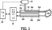
図1は、関連するサンプル100において光学深さD (以下の図3及び4参照) を評価するために用いられることができる光学装置の模式図である。この光学装置は、初期偏光P_0を有する放射線20を放射することが可能な放射源10を有する。放射源10は、例えば従来のレーザ、又はサンプルに向けた光学経路に沿った任意の位置で光学的に接続された適切な偏波フィルタを有するタングステンランプであることができる。「放射線」という用語によって、任意の種類の適切な放射線が、本発明に適用されることができることが理解されるべきであり、例えば、赤外線(IR)光、可視光、紫外線(UV)光及び(軟)X線が適用されることができる。
FIG. 1 is a schematic diagram of an optical device that can be used to evaluate the optical depth D (see FIGS. 3 and 4 below) in an associated
加えて、第1(30a)及び第2(30b)放射線ガイドが光学装置に含まれ、第1及び第2放射線ガイドは、例えば光ファイバ又は他の適切な光学ガイド手段であることができる。第1放射線ガイド30aは、図1に示すようにサンプル100に放射線20を放射するための放射源10に光学的に接続し、第1放射線ガイド30aは実質的に偏光維持特性を有する。放射源10は、補助放射線ガイド11によって、第1放射線ガイド30aに光学的に接続していることができる。
In addition, first (30a) and second (30b) radiation guides are included in the optical device, and the first and second radiation guides can be, for example, optical fibers or other suitable optical guide means. The
図1に概略的に示されるように、第1及び第2放射線ガイドは、互いに実質的に揃えられるそれらそれぞれの端部30a'及び30b'を有し、これらの端部はさらに、サンプル100から反射された放射線25a及び25bを取り込むように配置される。第1及び第2放射線ガイドのこの光学構成によって、本発明による光学装置によって差分経路長分光(DPL)を実行することが可能である。DPLについて詳しくは、読者はWO2005/029051(Amelink及びSterenborg) を参照されたい(この文献は全体として本願明細書に引用したものとする)。
As schematically shown in FIG. 1, the first and second radiation guides have their respective ends 30 a ′ and 30 b ′ that are substantially aligned with each other, and these ends further from the
光学装置はさらに、第1(30a)及び第2(30b)放射線ガイドに光学的に接続している検出器40を含む。検出器40は、光学サブバンド内で、以下の指標を測定するように配置される。
-反射された放射線25の第1偏光P_1。
-反射された放射線25の第2偏光P_2。当該第2偏光P_2は第1偏光P_1と異なる。
-それぞれ第1(30a)及び第2(30b)放射線ガイドにおける反射された放射線25a及び25bの第1(I_1)及び第2(I_2)強度。
The optical device further includes a
-The first polarization P_1 of the reflected
-The second polarization P_2 of the reflected
The first (I_1) and second (I_2) intensities of the reflected
検出器40は、例えば適切な偏光検出手段(例えば偏光フィルタ又は対応する光学ユニット) を有する一つ以上の分光器であることができる。したがって、測定された第1(I_1)及び第2(I_2)強度は、前記光学サブバンドによって定められるような特定の放射線バンドのスペクトログラフであることができる。反射された放射線25の第1偏光P_1及び第2偏光P_2(当該第2偏光P_2は第1偏光P_1と異なる)を検出することによって、光学装置によって偏光光散乱分光(PLSS)を実行することが可能である。PLSSについて詳しくは、読者は、V. Backman et al. in IEEE J. Selected Topics Quantum Electron., Vol. 5, No. 4, July/August 1999, p. 1019を参照されたい(この文献は全体として本願明細書に引用したものとする)。
The
加えて、処理手段60が検出器40に使用可能な状態で接続しており、この処理手段は、光学サブバンド内で第1(f)及び第2(g)スペクトル関数を計算するように適応され、両方のスペクトル関数(f, g)は、サンプル中の単散乱現象を実質的に示す。それでもやはり、上で説明されるように、二重散乱現象、三重散乱現象などからの第1(f)及び/又は第2(g)スペクトル関数への徐々に弱まる寄与も存在する場合がある。処理手段は、当業者によって容易に理解されるように、一つ以上のデータプロセッサ及び/又はデジタルシグナルプロセッサ上で動作するコンピュータソフトウェアとして実現されることができる。
In addition, a processing means 60 is operatively connected to the
第1スペクトル関数(f)は、反射された放射線25の第1(P_1)偏光と反射された放射線25の第2(P_2)偏光との間の偏光の差分の測度である。P_1及びP_2の相対的な位置で図1に示されるように、第1及び第2偏光は、第1放射線ガイド25aによって取り込まれる反射光25aから検出されることができるが、代わりに又は更に、第1及び第2偏光は、第2放射線ガイド25bによって取り込まれる反射光25bから検出されることができる(図1に示されない)。
The first spectral function (f) is a measure of the difference in polarization between the first (P_1) polarization of the reflected
第2スペクトル関数(g)は、放射線の第1(25a)及び第2(25b)ビームで反射された放射線の第1(I_1)及び第2(I_2)強度間の強度の差分の測度である。 The second spectral function (g) is a measure of the intensity difference between the first (I_1) and second (I_2) intensities of the radiation reflected by the first (25a) and second (25b) beams of radiation. .
処理手段60は、単散乱現象がサンプル100の中で実質的に同じ光学深さ(D)から生じるかどうかを評価するために、第1(f)及び第2(g)スペクトル関数の間の相関(C)の測度を計算するようにさらに配置される。
The processing means 60 determines whether the single scattering phenomenon occurs in the
図2は、PLSS(上部)及びDPL(下部)のための光学経路の模式図である。 FIG. 2 is a schematic diagram of optical paths for PLSS (upper part) and DPL (lower part).
PLSSに対して、入射光20の初期偏光はP_0によって示される。後方散乱に応じて、反射された光25は、検出器40(図2に示されない)が測定する少なくとも2つの成分P_1及びP_2を持つ特有の偏光を有する。反射された放射線25の第1(P_1)及び第2(P_2)偏光は、2つの実質的に直交する方向を指すように示され、他の相対的な方向も可能であるが、これが2つの測定された偏光方向の間の最大差分を有利にもたらすことができる。一般的に、放射源10(例えば固体レーザ)は、(図2に示されるように)測定される第1偏光(P_1)又は測定される第2(P_2)偏光の偏光面に実質的に平行な面中に直線偏光している初期偏光P_0を有する放射線を放射する。
For PLSS, the initial polarization of
DPLのために、反射された放射線25a及び25bの第1 (I_1)及び第2強度(I_2)間の強度差分が、それぞれ、更なる分析のために利用される。第1及び第2放射線ガイド30a及び30b(図示せず)の相対的な位置は、もちろん、どんな種類の情報が強度の差分信号から得られるかに関して非常に重要である。同様に、放射線ガイド(例えば光ファイバ) の有効径は、DPL分光にとって非常に重要である。目安として、光ファイバの直径は、DPLのための組織へのプロービング深さの約2倍である。
For DPL, the intensity difference between the first (I_1) and second intensity (I_2) of the reflected
図3は、単散乱現象に対する関連するサンプル100の中の光学経路の模式図である。図3に示されたように、入射放射線20は、特定の光学深さDでサンプル100に侵入し、サンプル100内の部位における光学的相互作用に応じて、特定の方向に反射される放射線25が存在する。反射された放射線25を光学装置によって測定するために、図3に示されるように、反射された放射線25は、おおよそ又は正確に入射放射線20の方向に後方散乱されることが通常必要である。しかしながら、レンズ及び/又は放射線ガイド30のより広い直径によって、反射された放射線25の取込みの立体角を増加させることができる。
FIG. 3 is a schematic diagram of the optical path in the
図4は、多重散乱現象に対する関連するサンプル100の中の光学経路の模式図である。図3と同様に、入射放射線20はサンプル100内の部位において散乱され、そして引き続いて、反射された放射線25の光学経路を示している矢印25の2つの変わり目によって示されるように、反射された放射線25はサンプル100の中で二回散乱する。したがって検出される放射線25は光学深さD'に侵入し、したがって反射された放射線25はこの深さのサンプルに関する情報を含み、この情報は3つの散乱現象の要約された寄与であり、各々の散乱現象から個々の寄与を分離することはほとんどできない。
FIG. 4 is a schematic diagram of the optical path in the
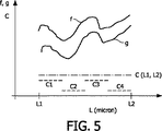
図5は、垂直軸に沿った第1(f)及び第2(g)スペクトル関数、並びに水平軸に沿った波長(L (μm) )によるグラフを示す。2つのスペクトル関数は、L1からL2までの光学サブバンドの中で示される。第1(f)及び第2(g)スペクトル関数の間の相関Cは、以下のように正規化によって計算されることができる。

図5において2つのスペクトル関数の下に、計算された相関C(L1, L2)が定数として示される。相関C(L1, L2)は、2つのスペクトル関数(f, g)をもたらす散乱現象がサンプル100内の同じ光学的深さDから生じていることの確かさの許容できるレベルを定める予め定められた値と比較されることができる。相関のレベルが予め定められた値と比較して許容できない場合、処理手段60は、検出器40の光学サブバンドL1,L2を調整することができ、放射源10の放射線20(電力、波長、繰り返し周波数など)を変更することができ、第1(25a)及び第2(25b)放射線ガイドの相対的な位置を修正することができ、第1(25a)及び/若しくは第2(25b)放射線ガイドの直径を変更することを提案することができ、並びに/又は、検出器40の設定(サンプリング速度、感度など)を変更することができる。処理手段60は、光学装置を制御しているオペレータの許可なしでこれらの変更又は修正を開始するように手配されることができ、又は処理手段は、オペレータの許可を求めることができ、あるいは処理手段は、オペレータにいくつかの変更(例えば他のセットの放射線ガイドを用いることにより放射線ガイドの直径を変えること)を提案することができる。
In FIG. 5, the calculated correlation C (L1, L2) is shown as a constant under the two spectral functions. The correlation C (L1, L2) is a predetermined that defines an acceptable level of certainty that the scattering phenomenon that results in the two spectral functions (f, g) originates from the same optical depth D in the
あるいは相関Cは、4つの相関C1, C2, C3及びC4によって示されるように、光学サブバンド内の複数の領域において処理手段60によって計算されることができる。4つの領域は、明確にするために重なり合わないように示されるが、これらの領域は互いに重なる場合もある。処理手段は引き続いて、光学装置によるその後の光学測定のための最適な相関(C)の領域を選択することができ、特に、後の診断のための最適な相関(C)が選択されることができる。 Alternatively, the correlation C can be calculated by the processing means 60 in a plurality of regions within the optical subband, as indicated by the four correlations C1, C2, C3 and C4. The four regions are shown not to overlap for clarity, but these regions may overlap each other. The processing means can subsequently select the region of optimal correlation (C) for subsequent optical measurements by the optical device, in particular that the optimal correlation (C) for subsequent diagnosis is selected. Can do.
他の一実施例において、処理手段60は、相関Cの全体の値を得るために、光学サブバンドL1, L2 内の複数の領域(例えば図5の4つの領域)からの相関を加算することができる。あるいは相関は、各々の相関に対する固有の重み付けで合計されることができ、重みは、見いだされる特定の相関(例えばC1, C2など)、予め定められたスペクトル特性(例えばfの最大値若しくは最小値)及び/又はスペクトル領域(波長L)によって、決定される。 In another embodiment, the processing means 60 adds the correlations from multiple regions (eg, the four regions in FIG. 5) in the optical subbands L1, L2 to obtain the overall value of the correlation C. Can do. Alternatively, the correlation can be summed with a unique weight for each correlation, the weight being the specific correlation found (e.g. C1, C2, etc.), a predetermined spectral characteristic (e.g. the maximum or minimum value of f) ) And / or spectral region (wavelength L).
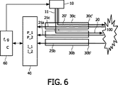
図6は本発明の他の光学装置の模式図であり、第3放射線ガイド30cが、サンプル100に初期偏光P_0を有する放射線20'を伝えるために配置される。図6に示される光学装置は、その他の点では図1に示される光学装置と同様である。第3放射線ガイド30cは、第1及び第2放射線ガイドの端部30a, 30bにそれぞれ実質的に揃えられる端部30cを持つことができる。第3放射線ガイド25aを通る放射線20'に平行に、第1放射線ガイドは放射線20をサンプル100に伝え、PLSSが図6に示すように反射された光25cを用いて追加された第3放射線ガイド30cでもっぱら実行されることができるので、放射線20は必ずしも偏光を必要とするわけではない。この実施例において、放射源10は、2つの別々の相互に独立した放射源に分割されることができる(図6に示されない)。光学装置のこの実施の形態は、PLSS及びDPLが互いに独立して実行されることができるという利点を持ち、それによって、第1(30a)及び/又は第2(30b)放射線ガイドが両方の種類の分光を実行することが可能でなければならないという制約のない光学装置を設計することを可能にする。
FIG. 6 is a schematic diagram of another optical device of the present invention, in which a
図7は、相関Cに依存して第1(30a)及び第2(30b)放射線ガイドの間のそれぞれの端部30a'及び30b'の距離d(二重矢印によって示される)を変えるように配置される駆動手段(図示せず)を含む他の光学装置の模式図である。したがって、相関Cは、距離dの関数として最適化されることができる。第1及び第2スペクトル関数は、現在利用可能な光学装置によって、通常すばやく(一秒未満で)見いだされることができ、そして同様に、相関Cは従来の計算手段によってさらにより短時間に見つけることができ、これは、光学装置が患者に適用される場合であっても、相関及び放射線ガイド距離dのそのような最適化を実行するための時間が多くの場合存在することを意味する。したがって、本発明の光学装置によるin-vivo特性解析が実行可能である。図7に示される光学装置は、図1に示される光学装置とその他の点では同様であり、検出器40及び処理手段60は明確にするために省略されている。
FIG. 7 shows that depending on the correlation C, the distance d (indicated by a double arrow) of each
図8は、本発明による方法のフローチャートである。この方法は、サンプル100中の光学深さDを評価するための光学装置を作動することを可能にし、当該方法は以下のステップを有する。
FIG. 8 is a flowchart of the method according to the present invention. This method makes it possible to operate an optical device for evaluating the optical depth D in the
S1: 放射源10によって初期偏光P_0を持つ放射線20を放射する。
S1:
S2: サンプルに対して第1(30a)及び第2(30b)放射線ガイドを配置する。第1放射線ガイド30aは、サンプルに放射線20を放射するように放射源に光学的に接続している。第1及び第2放射線ガイドは、互いに実質的に揃えられたそれらそれぞれの端部30a'及び30b'を持つ。端部はさらに、サンプルから反射された放射線25a及び25bを取り込むように配置される。
S2: First (30a) and second (30b) radiation guides are placed on the sample. The
S3: 第1及び第2放射線ガイドに光学的に接続される検出器40を提供する。検出器は、光学サブバンドの中で、以下の指標を測定するように配置される。
- 反射された放射線25の第1偏光P_1。
- 反射された放射線25の第2偏光P_2。当該第2偏光P_2は第1偏光P_1と異なる。
- それぞれ第1 (30a)及び第2(30b)放射線ガイドにおける反射された放射線25a及び25bの第1及び第2強度I_1及びI_2。
S3: Provide a
-The first polarization P_1 of the reflected
-Second polarization P_2 of reflected
The first and second intensities I_1 and I_2 of the reflected
S4: 使用可能な状態で検出器に接続している処理手段60を提供する。この処理手段は、光学サブバンド内の第1(f)及び第2(g)スペクトル関数を計算するように適応される。両方のスペクトル関数(f, g)はサンプル中の単散乱現象を実質的に示す。
- 第1スペクトル関数 (f) は、反射された放射線25の第1 (P_1) 偏光と反射された放射線25の第2 (P_2) 偏光との間の偏光の差分の測度である。
- 第2のスペクトル関数 (g) は、反射された放射線の第1及び第2強度I_1, I_2の間の強度の差分の測度である。
S4: Provide a processing means 60 connected to the detector in a usable state. This processing means is adapted to calculate the first (f) and second (g) spectral functions in the optical subband. Both spectral functions (f, g) substantially indicate a single scattering phenomenon in the sample.
The first spectral function (f) is a measure of the difference in polarization between the first (P_1) polarization of the reflected
The second spectral function (g) is a measure of the difference in intensity between the first and second intensities I_1, I_2 of the reflected radiation.
S5: 単散乱現象がサンプル内の実質的に同じ光学深さDから生じているかどうかを評価するために、第1 (f) 及び第2 (g) スペクトル関数の間の相関Cの測度を処理手段60によって計算する。 S5: Process the measure of the correlation C between the first (f) and second (g) spectral functions to evaluate whether the single scattering phenomenon originates from substantially the same optical depth D in the sample Calculate by means 60.
本発明は、ハードウェア、ソフトウェア、ファームウェア又はそれらの任意の組み合わせを含む任意の適切な形態で実現されることができる。本発明又は本発明のいくつかの特徴は、一つ以上のデータプロセッサ及び/又はデジタルシグナルプロセッサ上で動作するコンピュータソフトウェアとして実現されることができる。本発明の実施の形態の要素及びコンポーネントは、任意の適切な態様で、物理的に、機能的に、そして論理的に実現されることができる。実際に、機能性は、単一のユニットで、複数のユニットで又は他の機能ユニットの一部として実現されることができる。このように、本発明は、単一のユニットで実現されることができ、又は異なるユニット及びプロセッサの間で物理的及び機能的に分散されることができる。 The invention can be implemented in any suitable form including hardware, software, firmware or any combination of these. The invention or some features of the invention can be implemented as computer software running on one or more data processors and / or digital signal processors. The elements and components of an embodiment of the invention may be physically, functionally and logically implemented in any suitable manner. Indeed, the functionality can be realized in a single unit, in multiple units or as part of another functional unit. Thus, the present invention can be implemented in a single unit or can be physically and functionally distributed between different units and processors.
本発明が特定の実施の形態に関して述べられたが、本願明細書において記載される特定の形態に制限されることは意図されない。むしろ、本発明の範囲は、添付の請求の範囲によってのみ制限される。請求項中の「含む、有する」などの用語は、他の要素又はステップの存在を除外しない。加えて、個々の特徴が異なる請求項に含まれる場合があるが、これらはあるいは有利に組み合わせられることができ、そして、別々の請求項に含まれることは、特徴の組み合わせが実行可能でない及び/又は有益でないことを意味しない。加えて、単数形の参照は、複数を除外しない。したがって、"a"、 "an"、"第1"、"第2"などは複数を除外しない。さらに、請求項中の参照記号は、範囲を制限するものとして解釈されてはならない。 Although the invention has been described with reference to particular embodiments, it is not intended to be limited to the specific form set forth herein. Rather, the scope of the present invention is limited only by the accompanying claims. Terms such as “comprising” in the claims do not exclude the presence of other elements or steps. In addition, although individual features may be included in different claims, they may alternatively be combined, and included in separate claims that a combination of features is not feasible and / or Or does not mean that it is not beneficial. In addition, singular references do not exclude a plurality. Therefore, “a”, “an”, “first”, “second” and the like do not exclude a plurality. Furthermore, reference signs in the claims shall not be construed as limiting the scope.
Claims (18)
当該装置は、放射源、第1放射線ガイド、第2放射線ガイド、検出器及び処理手段を有し、
前記放射源は、初期偏光を持つ放射線を放射することができ、
第1放射線ガイドは、前記サンプルに放射線を放射するために前記放射源に光学的に接続し、第1及び第2放射線ガイドは、実質的に互いに揃えられたそれぞれの端部を備え、前記端部はさらに、前記サンプルから反射された放射線を取り込むように配置され、
前記検出器は、第1及び第2放射線ガイドに光学的に接続し、前記検出器は、光学サブバンド内で、
- 反射された放射線の第1偏光、
- 反射された放射線の、第1偏光とは異なる第2偏光、
- それぞれ第1及び第2放射線ガイドにおける反射された放射線の第1及び第2強度、
の指標を測定し、
前記処理手段は前記検出器に動作可能に接続し、前記処理手段は、前記光学サブバンド内で第1及び第2スペクトル関数を計算し、両方のスペクトル関数は、前記サンプル中の単散乱現象を実質的に示し、
- 第1スペクトル関数は、反射された放射線の第1偏光と反射された放射線の第2偏光との間の偏光の差の測度であり、
- 第2スペクトル関数は、反射された放射線の第1及び第2強度の間の強度の差の測度であり、
前記処理手段はさらに、単散乱現象が前記サンプル内の実質的に同じ光学深さから生じているかを評価するために、第1及び第2スペクトル関数の間の相関の測度を計算する、光学装置。An optical device for evaluating the optical depth in a relevant sample , comprising:
The device may have a radiation source, a first radiation guide, the second radiation guide, the detector and processing means,
The radiation source is, and can radiate the radiation with an initial polarization,
A first radiation guide is optically connected to the radiation source for emitting radiation to the sample, and the first and second radiation guides have respective ends substantially aligned with each other , the ends The portion is further arranged to capture radiation reflected from the sample ;
The detector is optically connected to the first and second radiation guide, the detector, in the optical sub-band,
-The first polarization of the reflected radiation ,
-A second polarization of the reflected radiation different from the first polarization ,
-First and second intensities of reflected radiation in the first and second radiation guides, respectively ;
Measure the indicators of
The processing means is operatively connected to the detector, the processing means calculates first and second spectral functions within the optical subband , both spectral functions representing a single scattering phenomenon in the sample. substantially shows,
- the first spectral function, Ri measure der of the difference in polarization between the second polarized light reflected from the first polarization of the reflected radiation radiation,
- the second spectral function, Ri measure der difference in intensity between the first and second intensity of the reflected radiation,
Said processing means further for single scattering events to evaluate whether the result from substantially the same optical depth within the sample, to calculate a measure of correlation between the first and second spectral function, optical device .
前記カテーテルは、第1放射線ガイド及び第2放射線ガイドを有し、
第1放射線ガイドは、サンプルに放射線を放射するために放射源に光学的に接続し、第1及び第2放射線ガイドは、実質的に互いに揃えられたそれぞれの端部を備え、前記端部はさらに、前記サンプルから反射された放射線を取り込むように配置され、
前記光学装置は、放射源、検出器及び処理手段を有し、
前記放射源は、初期偏光を持つ放射線を放射することができ、
前記検出器は、第1及び第2放射線ガイドに光学的に接続し、前記検出器は、光学サブバンド内で、
- 反射された放射線の第1偏光、
- 反射された放射線の、第1偏光とは異なる第2偏光、
- それぞれ第1及び第2放射線ガイドにおける反射された放射線の第1及び第2強度、
の指標を測定し、
前記処理手段は前記検出器に動作可能に接続し、前記処理手段は、前記光学サブバンド内で第1及び第2スペクトル関数を計算し、両方のスペクトル関数は、前記サンプル中の単散乱現象を実質的に示し、
- 第1スペクトル関数は、反射された放射線の第1偏光と反射された放射線の第2偏光との間の偏光の差の測度であり、
- 第2スペクトル関数は、反射された放射線の第1及び第2強度の間の強度の差の測度であり、
前記処理手段はさらに、単散乱現象が前記サンプル内の実質的に同じ光学深さから生じているかを評価するために、第1及び第2スペクトル関数の間の相関の測度を計算する、カテーテル。 A catheter for cooperating with optical science device,
The catheter, have a first radiation guide and a second radiation guide,
The first radiation guide is optically connected to a radiation source for emitting radiation to the sample , the first and second radiation guides having respective ends substantially aligned with each other , the ends being And is arranged to capture radiation reflected from the sample ,
Before SL optical science apparatus, it has a radiation source, detector and processing means,
The radiation source can emit radiation having an initial polarization ;
The detector is optically connected to the first and second radiation guide, the detector, in the optical sub-band,
-The first polarization of the reflected radiation ,
-A second polarization of the reflected radiation different from the first polarization ,
-First and second intensities of reflected radiation in the first and second radiation guides, respectively ;
Measure the indicators of
The processing means is operatively connected to the detector, the processing means calculates first and second spectral functions within the optical subband , both spectral functions representing a single scattering phenomenon in the sample. substantially shows,
- the first spectral function, Ri measure der of the difference in polarization between the second polarized light reflected from the first polarization of the reflected radiation radiation,
- the second spectral function, Ri measure der difference in intensity between the first and second intensity of the reflected radiation,
The processing means further calculates a measure of correlation between the first and second spectral functions to assess whether a single scattering phenomenon is arising from substantially the same optical depth in the sample .
放射源によって初期偏光を持つ放射線を放射するステップ、
前記サンプルに対して第1放射線ガイド及び第2放射線ガイドを配置するステップであって、第1放射線ガイドは、前記サンプルに放射線を放射するために前記放射源に光学的に接続し、第1及び第2放射線ガイドは、実質的に互いに揃えられたそれぞれの端部を備え、前記端部はさらに、前記サンプルから反射された放射線を取り込むように配置されるステップ、
第1及び第2放射線ガイドに光学的に接続している検出器を提供するステップであって、前記検出器は、光学サブバンド内で、
- 反射された放射線の第1偏光、
- 反射された放射線の、第1偏光とは異なる第2偏光、
- それぞれ第1及び第2放射線ガイドにおける反射された放射線の第1及び第2強度、
の指標を測定するステップ、
前記検出器に動作可能に接続している処理手段を提供するステップであって、前記処理手段は、前記光学サブバンド内で第1及び第2スペクトル関数を計算し、両方のスペクトル関数は、前記サンプル中の単散乱現象を実質的に示し、
- 第1スペクトル関数は、反射された放射線の第1偏光と反射された放射線の第2偏光との間の偏光の差の測度であり、
- 第2スペクトル関数は、反射された放射線の第1及び第2強度の間の強度の差の測度であるステップ、
前記処理手段によって、単散乱現象が前記サンプル内の実質的に同じ光学深さから生じているかを評価するために、第1及び第2スペクトル関数の間の相関の測度を計算するステップ、を有するコンピュータプログラム。According to the method of operating an optical device for evaluating the optical depth in a sample, the computer system having at least one computer and combined data storage means which allows it to control the optical device, a computer program there, the method comprising:
Emitting radiation with initial polarization by a radiation source ;
Disposing a first radiation guide and a second radiation guide relative to the sample, the first radiation guide, the optically connected to the radiation source for emitting radiation to the sample, the first and the second radiation guide is provided with a respective end portion substantially aligned with each other, the end Ru is further arranged to capture radiation reflected from the sample step,
Comprising: providing a detector which is optically coupled to the first and second radiation guide, the detector, in the optical sub-band,
-The first polarization of the reflected radiation ,
-A second polarization of the reflected radiation different from the first polarization ,
-First and second intensities of reflected radiation in the first and second radiation guides, respectively ;
Measuring the indicators of,
Providing processing means operably connected to the detector , wherein the processing means calculates first and second spectral functions within the optical subband , both spectral functions being substantially shows the single-scattering phenomenon in the sample,
- the first spectral function, Ri measure der of the difference in polarization between the second polarized light reflected from the first polarization of the reflected radiation radiation,
- the second spectral function, Ru measure der difference in intensity between the first and second intensity of the reflected radiation step,
By said processing means, in order to single scattering phenomenon to assess whether the result from substantially the same optical depth within the sample, comprising the step of computing the measures of correlation between the first and second spectral function Computer program .
Applications Claiming Priority (5)
| Application Number | Priority Date | Filing Date | Title |
|---|---|---|---|
| US89069507P | 2007-02-20 | 2007-02-20 | |
| US60/890,695 | 2007-02-20 | ||
| US90842207P | 2007-03-28 | 2007-03-28 | |
| US60/908,422 | 2007-03-28 | ||
| PCT/IB2008/050575 WO2008102294A2 (en) | 2007-02-20 | 2008-02-18 | An optical device for assessing optical depth in a sample |
Publications (3)
| Publication Number | Publication Date |
|---|---|
| JP2010519520A JP2010519520A (en) | 2010-06-03 |
| JP2010519520A5 JP2010519520A5 (en) | 2011-04-21 |
| JP4796652B2 true JP4796652B2 (en) | 2011-10-19 |
Family
ID=39710588
Family Applications (1)
| Application Number | Title | Priority Date | Filing Date |
|---|---|---|---|
| JP2009549885A Expired - Fee Related JP4796652B2 (en) | 2007-02-20 | 2008-02-18 | Optical device for evaluating the optical depth in a sample |
Country Status (8)
| Country | Link |
|---|---|
| US (1) | US8175690B2 (en) |
| EP (1) | EP2112901B1 (en) |
| JP (1) | JP4796652B2 (en) |
| CN (1) | CN101616627B (en) |
| AT (1) | ATE505130T1 (en) |
| DE (1) | DE602008006170D1 (en) |
| RU (1) | RU2469639C2 (en) |
| WO (1) | WO2008102294A2 (en) |
Families Citing this family (4)
| Publication number | Priority date | Publication date | Assignee | Title |
|---|---|---|---|---|
| CN103037751B (en) * | 2010-11-30 | 2015-06-10 | 松下电器产业株式会社 | Image processing device |
| US9675415B2 (en) * | 2012-02-28 | 2017-06-13 | Koninklijke Philips N.V. | Device for energy-based skin treatment |
| CN104280350B (en) * | 2013-07-03 | 2018-06-01 | 庞小峰 | A kind of early diagnosis of cancer of special sharpening and the device of therapeutic effect inspection |
| EP3451060A1 (en) * | 2017-08-28 | 2019-03-06 | ASML Netherlands B.V. | Substrate, metrology apparatus and associated methods for a lithographic process |
Citations (6)
| Publication number | Priority date | Publication date | Assignee | Title |
|---|---|---|---|---|
| JP2002535027A (en) * | 1999-01-25 | 2002-10-22 | マサチユセツツ・インスチチユート・オブ・テクノロジイ | Tissue polarization scattering spectroscopy |
| JP2002535645A (en) * | 1999-01-25 | 2002-10-22 | ニユートン・ラボラトリーズ・インコーポレーテツド | Imaging of tissue using polarized light |
| JP2004177257A (en) * | 2002-11-27 | 2004-06-24 | Olympus Corp | Determining method and determining device |
| JP2005501279A (en) * | 2001-08-23 | 2005-01-13 | ユニバーシティ・オブ・ワシントン | Collect depth-enhanced images |
| JP2005515472A (en) * | 2002-01-18 | 2005-05-26 | ニユートン・ラボラトリーズ・インコーポレーテツド | Spectroscopic diagnosis method and system |
| JP2007506114A (en) * | 2003-09-23 | 2007-03-15 | スティヒテング フォール デ テフニシェ ウェテンシャッペン | Method and apparatus for backscattering spectroscopy |
Family Cites Families (10)
| Publication number | Priority date | Publication date | Assignee | Title |
|---|---|---|---|---|
| AP931A (en) * | 1995-10-23 | 2001-02-02 | Cytometrics Inc | Method and apparatus for reflected imaging analysis. |
| US5719399A (en) * | 1995-12-18 | 1998-02-17 | The Research Foundation Of City College Of New York | Imaging and characterization of tissue based upon the preservation of polarized light transmitted therethrough |
| US6353226B1 (en) * | 1998-11-23 | 2002-03-05 | Abbott Laboratories | Non-invasive sensor capable of determining optical parameters in a sample having multiple layers |
| JP4845318B2 (en) * | 2000-03-28 | 2011-12-28 | ボード・オブ・リージエンツ,ザ・ユニバーシテイ・オブ・テキサス・システム | Method and apparatus for diagnostic multispectral digital imaging |
| US6640116B2 (en) * | 2000-08-18 | 2003-10-28 | Masimo Corporation | Optical spectroscopy pathlength measurement system |
| US7404929B2 (en) * | 2002-01-18 | 2008-07-29 | Newton Laboratories, Inc. | Spectroscopic diagnostic methods and system based on scattering of polarized light |
| RU2234242C2 (en) * | 2002-03-19 | 2004-08-20 | Федеральное государственное унитарное предприятие Научно-исследовательский институт "Полюс" | Method for determining biological tissue condition |
| US7307734B2 (en) | 2003-08-14 | 2007-12-11 | University Of Central Florida | Interferometric sensor for characterizing materials |
| US7587236B2 (en) * | 2004-01-08 | 2009-09-08 | Lawrence Livermore National Security, Llc | Optical spectroscopy for the detection of ischemic tissue injury |
| CA2597254A1 (en) * | 2005-02-09 | 2006-08-17 | Inlight Solutions, Inc. | Methods and apparatus for noninvasive determinations of analytes |
-
2008
- 2008-02-18 WO PCT/IB2008/050575 patent/WO2008102294A2/en active Application Filing
- 2008-02-18 AT AT08710071T patent/ATE505130T1/en not_active IP Right Cessation
- 2008-02-18 US US12/527,727 patent/US8175690B2/en not_active Expired - Fee Related
- 2008-02-18 CN CN2008800055488A patent/CN101616627B/en not_active Expired - Fee Related
- 2008-02-18 EP EP08710071A patent/EP2112901B1/en not_active Not-in-force
- 2008-02-18 DE DE602008006170T patent/DE602008006170D1/en active Active
- 2008-02-18 RU RU2009135012/14A patent/RU2469639C2/en not_active IP Right Cessation
- 2008-02-18 JP JP2009549885A patent/JP4796652B2/en not_active Expired - Fee Related
Patent Citations (6)
| Publication number | Priority date | Publication date | Assignee | Title |
|---|---|---|---|---|
| JP2002535027A (en) * | 1999-01-25 | 2002-10-22 | マサチユセツツ・インスチチユート・オブ・テクノロジイ | Tissue polarization scattering spectroscopy |
| JP2002535645A (en) * | 1999-01-25 | 2002-10-22 | ニユートン・ラボラトリーズ・インコーポレーテツド | Imaging of tissue using polarized light |
| JP2005501279A (en) * | 2001-08-23 | 2005-01-13 | ユニバーシティ・オブ・ワシントン | Collect depth-enhanced images |
| JP2005515472A (en) * | 2002-01-18 | 2005-05-26 | ニユートン・ラボラトリーズ・インコーポレーテツド | Spectroscopic diagnosis method and system |
| JP2004177257A (en) * | 2002-11-27 | 2004-06-24 | Olympus Corp | Determining method and determining device |
| JP2007506114A (en) * | 2003-09-23 | 2007-03-15 | スティヒテング フォール デ テフニシェ ウェテンシャッペン | Method and apparatus for backscattering spectroscopy |
Also Published As
| Publication number | Publication date |
|---|---|
| CN101616627A (en) | 2009-12-30 |
| WO2008102294A2 (en) | 2008-08-28 |
| EP2112901B1 (en) | 2011-04-13 |
| WO2008102294A3 (en) | 2008-11-20 |
| DE602008006170D1 (en) | 2011-05-26 |
| US20100113941A1 (en) | 2010-05-06 |
| EP2112901A2 (en) | 2009-11-04 |
| RU2469639C2 (en) | 2012-12-20 |
| CN101616627B (en) | 2011-08-03 |
| RU2009135012A (en) | 2011-03-27 |
| ATE505130T1 (en) | 2011-04-15 |
| US8175690B2 (en) | 2012-05-08 |
| JP2010519520A (en) | 2010-06-03 |
Similar Documents
| Publication | Publication Date | Title |
|---|---|---|
| US8355131B2 (en) | Device and method for acquiring image data from a turbid medium | |
| CN104968257B (en) | The imaging system of probe with the guiding of EO-1 hyperion camera | |
| TWI292030B (en) | High density multi-channel detecting device | |
| JP2009508571A (en) | Method and system for measuring composition directly under surface of specimen | |
| CN105980833B (en) | Method and apparatus for distributing plasma samples | |
| JP2015514446A (en) | Instrument for determining tissue characteristics | |
| JP6896906B2 (en) | Spectral image data processing device and two-dimensional spectroscopic device | |
| JP4796652B2 (en) | Optical device for evaluating the optical depth in a sample | |
| RU2009101910A (en) | X-RAY DEVICE AND METHOD OF VISUALIZING THE OBJECT TO BE TESTED | |
| Zhang et al. | Physiological model using diffuse reflectance spectroscopy for nonmelanoma skin cancer diagnosis | |
| JP5528966B2 (en) | Ultraviolet curable resin state estimation device, state estimation method and program | |
| Hall et al. | Simultaneous determination of the second-harmonic generation emission directionality and reduced scattering coefficient from three-dimensional imaging of thick tissues | |
| US20210196135A1 (en) | Blood vessel detection device and method therefor | |
| WO2007083691A1 (en) | Optical analyzer | |
| Saha et al. | Precision of Raman spectroscopy measurements in detection of microcalcifications in breast needle biopsies | |
| US9594024B2 (en) | Method for correcting a signal backscattered by a sample and associated device | |
| US9931072B2 (en) | Method for characterizing a sample by measurement of a backscattered optical signal | |
| JP2010504795A (en) | Equipment for optically analyzing the body | |
| WO2021210111A1 (en) | Measurement method, measurement device, measurement program, determination device, determination device operating method, and determination program | |
| TWI819004B (en) | Tissue identification device, tissue identification system,method for identifying tissue, testing method, tissue identification program, and storage medium | |
| CA2983792A1 (en) | Microscope device | |
| US20200359938A1 (en) | Lipid measurement device and method therefor | |
| CN102499647B (en) | Multi-mode low-coherence scattering spectrometer | |
| JP2005218760A (en) | Endoscopic apparatus | |
| Lu et al. | Measurement of the optical properties of apples by hyperspectral imaging for assessing fruit quality |
Legal Events
| Date | Code | Title | Description |
|---|---|---|---|
| A621 | Written request for application examination |
Free format text: JAPANESE INTERMEDIATE CODE: A621 Effective date: 20110218 |
|
| A521 | Request for written amendment filed |
Free format text: JAPANESE INTERMEDIATE CODE: A523 Effective date: 20110303 |
|
| A871 | Explanation of circumstances concerning accelerated examination |
Free format text: JAPANESE INTERMEDIATE CODE: A871 Effective date: 20110303 |
|
| A975 | Report on accelerated examination |
Free format text: JAPANESE INTERMEDIATE CODE: A971005 Effective date: 20110407 |
|
| A131 | Notification of reasons for refusal |
Free format text: JAPANESE INTERMEDIATE CODE: A131 Effective date: 20110414 |
|
| A521 | Request for written amendment filed |
Free format text: JAPANESE INTERMEDIATE CODE: A523 Effective date: 20110601 |
|
| TRDD | Decision of grant or rejection written | ||
| A01 | Written decision to grant a patent or to grant a registration (utility model) |
Free format text: JAPANESE INTERMEDIATE CODE: A01 Effective date: 20110630 |
|
| A01 | Written decision to grant a patent or to grant a registration (utility model) |
Free format text: JAPANESE INTERMEDIATE CODE: A01 |
|
| A61 | First payment of annual fees (during grant procedure) |
Free format text: JAPANESE INTERMEDIATE CODE: A61 Effective date: 20110729 |
|
| R150 | Certificate of patent or registration of utility model |
Free format text: JAPANESE INTERMEDIATE CODE: R150 |
|
| FPAY | Renewal fee payment (event date is renewal date of database) |
Free format text: PAYMENT UNTIL: 20140805 Year of fee payment: 3 |
|
| LAPS | Cancellation because of no payment of annual fees |