以下に、本発明に係る作動ガス循環型エンジンの実施形態を図面に基づいて詳細に説明する。なお、この実施形態によりこの発明が限定されるものではない。また、下記実施形態における構成要素には、当業者が置換可能かつ容易なもの、或いは実質的に同一のものが含まれる。
Hereinafter, an embodiment of a working gas circulation engine according to the present invention will be described in detail with reference to the drawings. In addition, this invention is not limited by this embodiment. In addition, constituent elements in the following embodiments include those that can be easily replaced by those skilled in the art or those that are substantially the same.
(実施形態1)
図1は、本発明の実施形態1に係る作動ガス循環型エンジンの模式的な概略構成図、図2は、本発明の実施形態1に係る作動ガス循環型エンジンの始動時を説明するタイムチャート、図3は、本発明の実施形態1に係る作動ガス循環型エンジンの酸素供給量マップ、図4は、本発明の実施形態1に係る作動ガス循環型エンジンの水素供給量マップ、図5は、本発明の実施形態1に係る作動ガス循環型エンジンの始動時の酸素供給制御を説明するフローチャート、図6は、本発明の実施形態1に係る作動ガス循環型エンジンの始動時の水素供給制御を説明するフローチャートである。(Embodiment 1)
FIG. 1 is a schematic schematic configuration diagram of a working gas circulation engine according to Embodiment 1 of the present invention, and FIG. 2 is a time chart for explaining a start time of the working gas circulation engine according to Embodiment 1 of the present invention. 3 is an oxygen supply amount map of the working gas circulation engine according to the first embodiment of the present invention, FIG. 4 is a hydrogen supply amount map of the working gas circulation engine according to the first embodiment of the present invention, and FIG. FIG. 6 is a flowchart for explaining oxygen supply control at the time of starting the working gas circulation engine according to Embodiment 1 of the present invention. FIG. 6 is a hydrogen supply control at the time of starting of the working gas circulation engine according to Embodiment 1 of the present invention. It is a flowchart explaining these.
本実施形態の作動ガス循環型エンジン1は、図1に示すように、反応物と、空気より比熱比の高い作動ガスとが供給され、反応物の反応に伴って作動ガスが膨張可能である燃焼室CCと、作動ガスを燃焼室CCの排気側から吸気側に循環させ再び燃焼室CCに供給可能な循環経路20と、反応物を供給する供給手段としての供給装置2とを備え、循環経路20を介して排気ガス中に含まれる作動ガスを燃焼室CCの排気側から吸気側に循環させ再び燃焼室CCに供給可能な、いわゆる、閉サイクルエンジンである。本実施形態では、反応物は、酸化剤としての酸素と、この酸化剤によって燃焼する燃料としての水素とが用いられ、本実施形態の供給装置2は、酸素供給手段としての酸化剤供給装置30と、水素供給手段としての燃料供給装置40とを有する。したがって、作動ガスは、燃焼室CCにおいて、酸化剤供給装置30から供給される酸素と燃料供給装置40から供給される水素との反応に伴って発生する反応熱、すなわち、水素の燃焼(発熱反応)に伴って発生する燃焼熱により膨張する。
As shown in FIG. 1, the working gas circulation engine 1 of the present embodiment is supplied with a reactant and a working gas having a higher specific heat ratio than air, and the working gas can expand as the reactant reacts. A combustion chamber CC, a circulation path 20 through which working gas can be circulated from the exhaust side to the intake side of the combustion chamber CC and can be supplied to the combustion chamber CC again, and a supply device 2 as a supply means for supplying reactants are provided. This is a so-called closed cycle engine in which the working gas contained in the exhaust gas can be circulated from the exhaust side to the intake side of the combustion chamber CC via the path 20 and supplied to the combustion chamber CC again. In this embodiment, the reactant uses oxygen as an oxidant and hydrogen as a fuel combusted by the oxidant, and the supply device 2 of the present embodiment has an oxidant supply device 30 as an oxygen supply means. And a fuel supply device 40 as a hydrogen supply means. Therefore, the working gas is generated in the combustion chamber CC in response to the reaction between oxygen supplied from the oxidant supply device 30 and hydrogen supplied from the fuel supply device 40, that is, combustion of hydrogen (exothermic reaction). ) To expand due to the combustion heat generated.
具体的には、作動ガス循環型エンジン1は、図1に示すように、酸化剤、この酸化剤によって燃焼する燃料及びこの燃料の燃焼に伴って動力を発生させる作動ガスが供給される燃焼室CCと、この燃焼室CCの吸気側と排気側とを繋ぐ循環経路20とを備え、その作動ガスが大気へと放出されることなく循環経路20を介して再び燃焼室CCに供給されるよう構成される。この作動ガス循環型エンジン1は、燃焼室CC内で燃料を燃焼させ、この燃料の燃焼に伴って作動ガスを熱膨張させて動力を発生させることで熱効率を向上するものである。
Specifically, as shown in FIG. 1, the working gas circulation engine 1 includes a combustion chamber to which an oxidant, a fuel combusted by the oxidant, and a working gas that generates power accompanying the combustion of the fuel are supplied. CC and a circulation path 20 connecting the intake side and the exhaust side of the combustion chamber CC are provided so that the working gas is supplied again to the combustion chamber CC via the circulation path 20 without being released to the atmosphere. Composed. This working gas circulation engine 1 improves thermal efficiency by burning fuel in a combustion chamber CC and generating power by thermally expanding the working gas as the fuel burns.
この作動ガス循環型エンジン1は、燃焼室CCが形成されるエンジン本体10と、燃焼室CCの吸気側と排気側とを繋ぐ循環経路20と、燃焼室CCに酸化剤を供給する酸化剤供給装置30と、燃焼室CCに燃料を供給する燃料供給装置40と、作動ガス循環型エンジン1の各部を制御する電子制御装置(ECU)50と、凝縮器60と、貯留タンク70とを備える。エンジン本体10の燃焼室CCと循環経路20とは、ともに作動ガスが充填されており、作動ガスは、燃焼室CCと循環経路20との間で循環する。なお、図1に例示するエンジン本体10は、1気筒のみを図示しているが、本発明の作動ガス循環型エンジン1は、これに限らず、多気筒のエンジン本体10も適用可能である。
The working gas circulation engine 1 includes an engine body 10 in which a combustion chamber CC is formed, a circulation path 20 that connects the intake side and the exhaust side of the combustion chamber CC, and an oxidant supply that supplies an oxidant to the combustion chamber CC. A device 30, a fuel supply device 40 that supplies fuel to the combustion chamber CC, an electronic control unit (ECU) 50 that controls each part of the working gas circulation engine 1, a condenser 60, and a storage tank 70 are provided. The combustion chamber CC and the circulation path 20 of the engine body 10 are both filled with working gas, and the working gas circulates between the combustion chamber CC and the circulation path 20. 1 shows only one cylinder, the working gas circulation engine 1 of the present invention is not limited to this, and a multi-cylinder engine body 10 can also be applied.
本実施形態の燃焼室CCは、エンジン本体10に形成される。このエンジン本体10の燃焼室CCは、酸化剤と、この酸化剤によって燃焼しここでは燃焼により水蒸気を生成する燃料と、作動ガスとが供給され、燃料の燃焼に伴って作動ガスが膨張可能であると共に燃料の燃焼後の排気ガスとして水蒸気と作動ガスとを排気可能なものである。
The combustion chamber CC of the present embodiment is formed in the engine body 10. The combustion chamber CC of the engine body 10 is supplied with an oxidant, a fuel that burns with the oxidant and generates steam by combustion, and a working gas, and the working gas can expand as the fuel burns. In addition, water vapor and working gas can be exhausted as exhaust gas after combustion of fuel.
具体的には、エンジン本体10は、燃焼室CCを形成するシリンダヘッド11、シリンダブロック12及びピストン13を備えている。ピストン13は、コネクティングロッド14を介してクランクシャフト19に連結し、シリンダヘッド11の下面の凹部11aとシリンダブロック12のシリンダボア12aとの間に区画される空間内に往復運動可能に配置される。燃焼室CCは、シリンダヘッド11の凹部11aの壁面とシリンダボア12aの壁面とピストン13の頂面13aとで囲まれた空間によって構成される。
Specifically, the engine body 10 includes a cylinder head 11, a cylinder block 12, and a piston 13 that form a combustion chamber CC. The piston 13 is connected to the crankshaft 19 via the connecting rod 14 and is disposed so as to be capable of reciprocating in a space defined between the recess 11 a on the lower surface of the cylinder head 11 and the cylinder bore 12 a of the cylinder block 12. The combustion chamber CC is configured by a space surrounded by the wall surface of the recess 11 a of the cylinder head 11, the wall surface of the cylinder bore 12 a, and the top surface 13 a of the piston 13.
エンジン本体10は、シリンダヘッド11に吸気ポート11b及び排気ポート11cが形成されている。吸気ポート11bと排気ポート11cとは、ともに循環経路20の一部をなすものである。吸気ポート11b、排気ポート11cは、それぞれ一端が燃焼室CC内に開口している。エンジン本体10は、吸気ポート11bの燃焼室CC側の開口部分に吸気弁15が配設されている。吸気弁15は、開弁時にこの吸気ポート11bの燃焼室CC側の開口を開く一方、閉弁時にこの吸気ポート11bの燃焼室CC側の開口を閉じるものである。エンジン本体10は、排気ポート11cの燃焼室CC側の開口部分に排気弁16が配設されている。排気弁16は、開弁時にこの排気ポート11cの燃焼室CC側の開口を開く一方、閉弁時にこの排気ポート11cの燃焼室CC側の開口を閉じるものである。
The engine body 10 has an intake port 11 b and an exhaust port 11 c formed in a cylinder head 11. Both the intake port 11b and the exhaust port 11c form part of the circulation path 20. One end of each of the intake port 11b and the exhaust port 11c opens into the combustion chamber CC. The engine body 10 is provided with an intake valve 15 at an opening portion of the intake port 11b on the combustion chamber CC side. The intake valve 15 opens the opening on the combustion chamber CC side of the intake port 11b when the valve is opened, and closes the opening on the combustion chamber CC side of the intake port 11b when the valve is closed. The engine body 10 is provided with an exhaust valve 16 at an opening portion of the exhaust port 11c on the combustion chamber CC side. The exhaust valve 16 opens the opening on the combustion chamber CC side of the exhaust port 11c when the valve is opened, and closes the opening on the combustion chamber CC side of the exhaust port 11c when the valve is closed.
吸気弁15や排気弁16としては、例えば、不図示のカムシャフトの回転と弾性部材(弦巻バネ)の弾発力に伴って開閉駆動されるものがある。この種の吸気弁15や排気弁16においては、そのカムシャフトとクランクシャフト19の間にチェーンやスプロケット等からなる動力伝達機構を介在させることによってそのカムシャフトをクランクシャフト19の回転に連動させ、予め設定された開閉時期に開閉駆動させる。また、このエンジン本体10は、吸気弁15と排気弁16の開閉時期やリフト量を変更可能な、いわゆる可変バルブタイミング&リフト機構等の可変バルブ機構を備えていてもよく、これにより、その吸気弁15や排気弁16の開閉時期やリフト量を運転条件に応じた好適なものへと変更できるようになる。さらにまた、このエンジン本体10は、このような可変バルブ機構と同様の作用効果を得るべく、電磁力を利用して吸気弁15や排気弁16を開閉駆動させる、いわゆる電磁駆動弁を適用してもよい。
As the intake valve 15 and the exhaust valve 16, for example, there are those that are opened and closed in accordance with the rotation of a camshaft (not shown) and the elastic force of an elastic member (string wound spring). In this type of intake valve 15 and exhaust valve 16, a camshaft is interlocked with the rotation of the crankshaft 19 by interposing a power transmission mechanism such as a chain or a sprocket between the camshaft and the crankshaft 19, Open / close drive is performed at a preset opening / closing timing. Further, the engine body 10 may include a variable valve mechanism such as a so-called variable valve timing & lift mechanism that can change the opening / closing timing and lift amount of the intake valve 15 and the exhaust valve 16. The opening / closing timing and lift amount of the valve 15 and the exhaust valve 16 can be changed to suitable ones according to the operating conditions. Furthermore, the engine body 10 is applied with a so-called electromagnetically driven valve that opens and closes the intake valve 15 and the exhaust valve 16 using electromagnetic force in order to obtain the same effect as the variable valve mechanism. Also good.
また、エンジン本体10は、吸気ポート11bの燃焼室CC側とは反対側の開口に吸気管17が接続される一方、排気ポート11cの燃焼室CC側とは反対側の開口に排気管18が接続されている。吸気管17と排気管18とは、ともに循環経路20の一部をなすものである。吸気管17は、筒状に形成され内部を流体が通過可能なものであり、後述するように燃焼室CCに作動ガスとしてのアルゴン(Ar)と、酸化剤としての酸素(O2)とを供給するための吸気通路である。つまり、燃焼室CCは、吸気弁15の開弁時に、この吸気管17から吸気ポート11bを介して酸化剤と作動ガスとが供給(吸気)される。一方、排気管18は、筒状に形成され内部を流体が通過可能なものであり、後述するように燃料としての水素(H2)の燃焼後の排気ガスとして、燃焼室CCから作動ガスとしてのアルゴン(Ar)と、水蒸気(H2O)とを排出するための排気通路である。つまり、燃焼室CCは、排気弁16の開弁時に、燃料の燃焼後の排気ガスとして、排気ポート11cを介して水蒸気と作動ガスとを排気管18に排気する。The engine body 10 has an intake pipe 17 connected to an opening of the intake port 11b opposite to the combustion chamber CC side, and an exhaust pipe 18 connected to an opening of the exhaust port 11c opposite to the combustion chamber CC side. It is connected. The intake pipe 17 and the exhaust pipe 18 together form part of the circulation path 20. The intake pipe 17 is formed in a cylindrical shape and allows fluid to pass therethrough. As will be described later, the combustion chamber CC contains argon (Ar) as a working gas and oxygen (O 2 ) as an oxidant. It is an intake passage for supplying. That is, when the intake valve 15 is opened, the oxidant and the working gas are supplied (intake) from the intake pipe 17 to the combustion chamber CC via the intake port 11b. On the other hand, the exhaust pipe 18 is formed in a cylindrical shape so that a fluid can pass therethrough. As will be described later, as an exhaust gas after combustion of hydrogen (H 2 ) as a fuel, the exhaust pipe 18 serves as a working gas from the combustion chamber CC. This is an exhaust passage for discharging argon (Ar) and water vapor (H 2 O). That is, when the exhaust valve 16 is opened, the combustion chamber CC exhausts water vapor and working gas to the exhaust pipe 18 through the exhaust port 11c as exhaust gas after combustion of fuel.
循環経路20は、排気管18に排気された排気ガス中に含まれる作動ガスを燃焼室CCの排気側から吸気側に循環させ再び燃焼室CCに供給可能なものである。循環経路20は、上述した吸気ポート11b及び排気ポート11cと、吸気ポート11bの他端と排気ポート11cの他端とを繋ぐ循環通路21とを含んで構成される。これにより、この循環経路20内と燃焼室CC内とは、基本的には閉塞された空間をなす。循環通路21は、筒状に形成され内部を流体が通過可能なものであり、上述の吸気管17と排気管18とは、この循環通路21の一部をなす。
The circulation path 20 can circulate the working gas contained in the exhaust gas exhausted to the exhaust pipe 18 from the exhaust side to the intake side of the combustion chamber CC and supply it again to the combustion chamber CC. The circulation path 20 includes the intake port 11b and the exhaust port 11c described above, and a circulation passage 21 that connects the other end of the intake port 11b and the other end of the exhaust port 11c. As a result, the circulation path 20 and the combustion chamber CC basically form a closed space. The circulation passage 21 is formed in a cylindrical shape and allows fluid to pass therethrough. The intake pipe 17 and the exhaust pipe 18 described above form part of the circulation passage 21.
この作動ガス循環型エンジン1は、循環経路20と燃焼室CCとからなる閉塞された空間内に作動ガスが充填される。作動ガス循環型エンジン1は、この作動ガスを循環経路20の吸気管17、吸気ポート11bから燃焼室CC内、燃焼室CC内から循環経路20の排気ポート11c、排気管18、そして、この排気ポート11c、排気管18から循環通路21を介して再び吸気管17、吸気ポート11bへと循環させる。つまり、循環経路20は、燃焼室CCの吸気側(吸気ポート11b側)と排気側(排気ポート11c側)とを燃焼室CCの外部で接続し、作動ガスを大気へと放出することなく再び燃焼室CCに供給する。さらに言えば、循環経路20は、両端が燃焼室CCに連通すると共に一端からは水蒸気と作動ガスとを含む排気ガスが燃焼室CCから流入し、他端からは燃焼室CCが吸気する酸化剤と作動ガスとが燃焼室CCに対して流出可能である。ここでは、作動ガス循環型エンジン1は、吸気弁15が開弁した際に、循環通路21の酸化剤、作動ガスが吸気管17、吸気ポート11bを介して燃焼室CCに供給される。また、作動ガス循環型エンジン1は、排気弁16が開弁した際に、燃焼室CC内の排気ガスが排気ポート11c、排気管18を介して循環通路21に排出される。
The working gas circulation engine 1 is filled with working gas in a closed space formed by the circulation path 20 and the combustion chamber CC. The working gas circulation engine 1 circulates the working gas through the intake pipe 17 of the circulation path 20, the intake port 11b into the combustion chamber CC, the exhaust port 11c of the circulation path 20 from the combustion chamber CC, the exhaust pipe 18, and the exhaust gas. The air is circulated from the port 11c and the exhaust pipe 18 through the circulation passage 21 to the intake pipe 17 and the intake port 11b again. That is, the circulation path 20 connects the intake side (intake port 11b side) and the exhaust side (exhaust port 11c side) of the combustion chamber CC outside the combustion chamber CC, and again without releasing the working gas to the atmosphere. Supply to combustion chamber CC. Furthermore, the circulator 20 has both ends communicating with the combustion chamber CC, an exhaust gas containing water vapor and working gas flows from one end into the combustion chamber CC, and an oxidant that the combustion chamber CC takes in from the other end. And the working gas can flow out to the combustion chamber CC. Here, in the working gas circulation engine 1, when the intake valve 15 is opened, the oxidant and working gas in the circulation passage 21 are supplied to the combustion chamber CC via the intake pipe 17 and the intake port 11b. In the working gas circulation engine 1, when the exhaust valve 16 is opened, the exhaust gas in the combustion chamber CC is discharged to the circulation passage 21 through the exhaust port 11 c and the exhaust pipe 18.
さらに具体的には、循環経路20の循環通路21は、例えば、第1循環通路21aと、第2循環通路21bとを含んで構成されている。第1循環通路21aは、吸気ポート11bの他端と後述する凝縮器60の作動ガス排出口60bとを繋ぐものである。また、第2循環通路21bは、排気ポート11cの他端とこの凝縮器60の排気ガス導入口60aとを繋ぐものである。上述の吸気管17は、第1循環通路21aの一部をなす一方、排気管18は、第2循環通路21bの一部をなす。
More specifically, the circulation path 21 of the circulation path 20 includes, for example, a first circulation path 21a and a second circulation path 21b. The first circulation passage 21a connects the other end of the intake port 11b and a working gas discharge port 60b of a condenser 60 described later. The second circulation passage 21 b connects the other end of the exhaust port 11 c and the exhaust gas inlet 60 a of the condenser 60. The intake pipe 17 described above forms part of the first circulation passage 21a, while the exhaust pipe 18 forms part of the second circulation passage 21b.
ここで、循環経路20と燃焼室CCとからなる閉塞された空間内に充填される作動ガスとしては、空気より比熱比の高いガスが用いられる。作動ガスは、例えば、単原子ガスが用いられる。ここでは、本実施形態の作動ガスは、空気よりも比熱比の高いものであって、例えば、単原子ガスであるアルゴン(Ar)やヘリウム(He)等の希ガスが用いられる。本実施形態では、作動ガスは、上述のようにアルゴン(Ar)を用いるものとして説明する。
Here, a gas having a higher specific heat ratio than air is used as the working gas filled in the closed space formed by the circulation path 20 and the combustion chamber CC. As the working gas, for example, a monoatomic gas is used. Here, the working gas of the present embodiment has a higher specific heat ratio than air, and for example, a rare gas such as argon (Ar) or helium (He) that is a monoatomic gas is used. In the present embodiment, the working gas is described as using argon (Ar) as described above.
酸素供給手段としての酸化剤供給装置30は、上述したように反応物を供給する供給装置2をなすものであり、反応物として酸素を供給するものである。本実施形態の酸化剤供給装置30は、酸化剤としての酸素を循環経路20、ここでは吸気ポート11bを介して燃焼室CCに供給する。酸化剤供給装置30は、酸化剤貯留タンク31と、酸化剤噴射手段32と、酸化剤供給通路33と、レギュレータ34と、酸化剤流量計35と、サージタンク36とを含んで構成される。
The oxidant supply device 30 serving as the oxygen supply means constitutes the supply device 2 that supplies the reactant as described above, and supplies oxygen as the reactant. The oxidant supply device 30 of the present embodiment supplies oxygen as an oxidant to the combustion chamber CC via the circulation path 20, here the intake port 11b. The oxidant supply device 30 includes an oxidant storage tank 31, an oxidant injection means 32, an oxidant supply passage 33, a regulator 34, an oxidant flow meter 35, and a surge tank 36.
酸化剤貯留タンク31は、酸化剤を高圧の状態で貯留するものである。酸化剤噴射手段32は、酸化剤貯留タンク31に貯留された酸化剤を吸気ポート11bに噴射し、この吸気ポート11bを介して酸化剤を燃焼室CCに供給するものである。酸化剤供給通路33は、酸化剤貯留タンク31と酸化剤噴射手段32とを繋ぐものである。レギュレータ34、酸化剤流量計35及びサージタンク36は、この酸化剤供給通路33上に設けられる。レギュレータ34と酸化剤流量計35とサージタンク36とは、酸化剤供給通路33における酸化剤の供給方向に対して、上流側(酸化剤貯留タンク31側)から下流側(酸化剤噴射手段32側)に向かってレギュレータ34、酸化剤流量計35、サージタンク36の順で設けられている。
The oxidant storage tank 31 stores the oxidant in a high pressure state. The oxidant injection means 32 injects the oxidant stored in the oxidant storage tank 31 to the intake port 11b and supplies the oxidant to the combustion chamber CC via the intake port 11b. The oxidant supply passage 33 connects the oxidant storage tank 31 and the oxidant injection means 32. The regulator 34, the oxidant flow meter 35 and the surge tank 36 are provided on the oxidant supply passage 33. The regulator 34, the oxidant flow meter 35, and the surge tank 36 are upstream (oxidant storage tank 31 side) to downstream (oxidant injection means 32 side) with respect to the oxidant supply direction in the oxidant supply passage 33. ), The regulator 34, the oxidant flow meter 35, and the surge tank 36 are provided in this order.
ここで、本実施形態の酸化剤噴射手段32は、酸化剤を吸気ポート11bに噴射可能なようにシリンダヘッド11に設けられる。この酸化剤噴射手段32は、電子制御装置50によって制御される、いわゆる、酸化剤噴射弁である。本実施形態の酸化剤供給装置30は、酸化剤噴射手段32が酸化剤を吸気ポート11bに噴射することで吸気ポート11bを通る作動ガスと混ぜ合わせて燃焼室CCに送り込ませることができる。この結果、酸化剤は、吸気弁15の開弁に伴い吸気ポート11bを介して作動ガスと共に燃焼室CCに供給されることになる。電子制御装置50は、例えば、運転者がこの作動ガス循環型エンジン1に要求する駆動力(要求エンジン負荷)やエンジン回転数等の運転状態に応じて燃料の噴射時期や噴射量、言い換えれば供給量を制御する。電子制御装置50は、例えば、通常の運転時では、後述するように運転者がこの作動ガス循環型エンジン1に要求する駆動力やエンジン回転数等の運転状態に基づいて設定される燃料の噴射時期や噴射量(供給量)に応じて酸化剤の噴射時期や噴射量(供給量)を制御する。
Here, the oxidant injection means 32 of the present embodiment is provided in the cylinder head 11 so that the oxidant can be injected into the intake port 11b. The oxidant injection means 32 is a so-called oxidant injection valve controlled by the electronic control unit 50. In the oxidant supply device 30 of this embodiment, the oxidant injection means 32 injects the oxidant into the intake port 11b, so that it can be mixed with the working gas passing through the intake port 11b and sent into the combustion chamber CC. As a result, the oxidant is supplied to the combustion chamber CC together with the working gas via the intake port 11b when the intake valve 15 is opened. The electronic control unit 50, for example, the fuel injection timing or the injection amount, in other words, the supply according to the driving state (requested engine load) required by the driver for the working gas circulation engine 1 and the operating state such as the engine speed. Control the amount. For example, during normal operation, the electronic control unit 50 is configured to inject fuel that is set on the basis of operating conditions such as driving force and engine speed required by the driver for the working gas circulation engine 1 as will be described later. The injection timing and injection amount (supply amount) of the oxidizing agent are controlled according to the timing and injection amount (supply amount).
レギュレータ34は、酸化剤供給通路33におけるレギュレータ34よりも下流側(酸化剤流量計35側)の圧力を電子制御装置50の指令に従った目標圧力に調整するものである。言い換えれば、このレギュレータ34は、酸化剤供給通路33における酸化剤の流量を制御するものである。また、酸化剤流量計35は、酸化剤供給通路33における酸化剤の流量を計測する手段であって、レギュレータ34で調整された酸化剤の流量の計測を行う。この酸化剤流量計35の計測信号は、電子制御装置50に送信される。また、サージタンク36は、酸化剤噴射手段32による酸化剤の噴射時に酸化剤供給通路33内に発生する脈動の低減を図るものである。
The regulator 34 adjusts the pressure downstream of the regulator 34 (oxidant flow meter 35 side) in the oxidant supply passage 33 to a target pressure according to a command from the electronic control unit 50. In other words, the regulator 34 controls the flow rate of the oxidant in the oxidant supply passage 33. The oxidant flow meter 35 is a means for measuring the flow rate of the oxidant in the oxidant supply passage 33 and measures the flow rate of the oxidant adjusted by the regulator 34. The measurement signal of the oxidant flow meter 35 is transmitted to the electronic control unit 50. The surge tank 36 is intended to reduce pulsation generated in the oxidant supply passage 33 when the oxidant injection means 32 injects the oxidant.
ここで、この酸化剤供給装置30が供給する酸化剤としては、上述のように酸素(O2)が用いられる。つまり、本実施形態の酸化剤貯留タンク31は、酸化剤としての酸素を例えば70MPa程度の高圧で貯留し、酸化剤噴射手段32は、この高圧の酸素(O2)を循環通路21に供給する。Here, oxygen (O 2 ) is used as the oxidant supplied by the oxidant supply device 30 as described above. That is, the oxidant storage tank 31 of this embodiment stores oxygen as an oxidant at a high pressure of, for example, about 70 MPa, and the oxidant injection unit 32 supplies this high-pressure oxygen (O 2 ) to the circulation passage 21. .
水素供給手段としての燃料供給装置40は、上述したように反応物を供給する供給装置2をなすものであり、反応物として水素を供給するものである。本実施形態の燃料供給装置40は、燃料としての水素を燃焼室CCに直接供給する。燃料供給装置40は、燃料貯留タンク41と、燃料噴射手段42と、燃料供給通路43と、レギュレータ44と、燃料流量計45と、サージタンク46とを含んで構成される。
The fuel supply device 40 as the hydrogen supply means constitutes the supply device 2 that supplies the reactant as described above, and supplies hydrogen as the reactant. The fuel supply device 40 of this embodiment directly supplies hydrogen as fuel to the combustion chamber CC. The fuel supply device 40 includes a fuel storage tank 41, a fuel injection means 42, a fuel supply passage 43, a regulator 44, a fuel flow meter 45, and a surge tank 46.
燃料貯留タンク41は、燃料を高圧の状態で貯留するものである。燃料噴射手段42は、燃料貯留タンク41に貯留された燃料を燃焼室CCに噴射するものである。燃料供給通路43は、燃料貯留タンク41と燃料噴射手段42を繋ぐものである。レギュレータ44、燃料流量計45及びサージタンク46は、この燃料供給通路43上に設けられる。レギュレータ44と、燃料流量計45と、サージタンク46とは、燃料供給通路43における燃料の供給方向に対して、上流側(燃料貯留タンク41側)から下流側(燃料噴射手段42側)に向かってレギュレータ44、燃料流量計45、サージタンク46の順で設けられている。
The fuel storage tank 41 stores fuel in a high pressure state. The fuel injection means 42 injects the fuel stored in the fuel storage tank 41 into the combustion chamber CC. The fuel supply passage 43 connects the fuel storage tank 41 and the fuel injection means 42. The regulator 44, the fuel flow meter 45, and the surge tank 46 are provided on the fuel supply passage 43. The regulator 44, the fuel flow meter 45, and the surge tank 46 are directed from the upstream side (the fuel storage tank 41 side) to the downstream side (the fuel injection means 42 side) with respect to the fuel supply direction in the fuel supply passage 43. The regulator 44, the fuel flow meter 45, and the surge tank 46 are provided in this order.
ここで、本実施形態の燃料噴射手段42は、燃料を燃焼室CC内に直接噴射可能なようにシリンダヘッド11に設けられる。この燃料噴射手段42は、電子制御装置50によって制御される、いわゆる、燃料噴射弁である。電子制御装置50は、例えば、通常の運転時では運転者がこの作動ガス循環型エンジン1に要求する駆動力(要求エンジン負荷)やエンジン回転数等の運転状態に応じて燃料の噴射時期や噴射量、言い換えれば供給量を制御する。
Here, the fuel injection means 42 of this embodiment is provided in the cylinder head 11 so that fuel can be directly injected into the combustion chamber CC. The fuel injection means 42 is a so-called fuel injection valve controlled by the electronic control unit 50. The electronic control unit 50, for example, in the normal operation, the fuel injection timing and injection according to the driving state (requested engine load) required by the driver for the working gas circulation engine 1 and the operating state such as the engine speed. The amount, in other words, the supply amount is controlled.
なお、運転者がこの作動ガス循環型エンジン1に要求する駆動力(要求エンジン負荷)は、例えば、通常の運転時においては作動ガス循環型エンジン1を搭載する車両のアクセル開度などに基づいて設定される。電子制御装置50は、例えば、作動ガス循環型エンジン1のエンジン回転数と要求する駆動力(要求エンジン負荷)とに基づいて、現在のエンジン回転数において、作動ガス循環型エンジン1に要求する駆動力(要求負荷)を得ることができる燃料の供給量を決定する。作動ガス循環型エンジン1のエンジン回転数は、例えばクランク角センサ51に基づいて検出することができる。クランク角センサ51は、例えば、作動ガス循環型エンジン1のクランクシャフト19の回転角度であるクランク角度を検出するものである。クランク角センサ51は、検出信号を電子制御装置50に送信する。電子制御装置50は、例えば、検出されたクランク角度に基づいて各気筒における吸気行程、圧縮行程、膨張行程、排気行程を判別すると共に、作動ガス循環型エンジン1の回転速度としてエンジン回転数(rpm)を算出する。なおここで、エンジン回転数は、言い換えれば、クランクシャフト19の回転速度に対応し、このクランクシャフト19の回転速度が高くなれば、クランクシャフト19の回転数であるエンジン回転数も高くなる。
The driving force (required engine load) required by the driver for the working gas circulation engine 1 is based on, for example, the accelerator opening degree of a vehicle on which the working gas circulation engine 1 is mounted during normal operation. Is set. For example, the electronic control unit 50 drives the operating gas circulation engine 1 to be requested at the current engine speed based on the engine speed of the working gas circulation engine 1 and the requested driving force (required engine load). The amount of fuel supply that can obtain the force (required load) is determined. The engine speed of the working gas circulation engine 1 can be detected based on, for example, a crank angle sensor 51. The crank angle sensor 51 detects, for example, a crank angle that is a rotation angle of the crankshaft 19 of the working gas circulation engine 1. The crank angle sensor 51 transmits a detection signal to the electronic control unit 50. For example, the electronic control unit 50 determines an intake stroke, a compression stroke, an expansion stroke, and an exhaust stroke in each cylinder based on the detected crank angle, and the engine speed (rpm) as the rotational speed of the working gas circulation engine 1. ) Is calculated. Here, the engine speed corresponds to the rotational speed of the crankshaft 19 in other words, and if the rotational speed of the crankshaft 19 increases, the engine rotational speed that is the rotational speed of the crankshaft 19 also increases.
レギュレータ44は、燃料供給通路43におけるレギュレータ44よりも下流側(燃料流量計45及びサージタンク46側)の圧力を設定圧力に調整するものである。言い換えれば、このレギュレータ44は、燃料供給通路43における燃料の流量を制御するものである。また、燃料流量計45は、燃料供給通路43における燃料の流量を計測する手段であって、レギュレータ44で調整された燃料の流量の計測を行う。この燃料流量計45の計測信号は、電子制御装置50に送信される。また、サージタンク46は、燃料噴射手段42による燃料の噴射時に燃料供給通路43内に発生する脈動の低減を図るものである。
The regulator 44 adjusts the pressure downstream of the regulator 44 in the fuel supply passage 43 (on the fuel flow meter 45 and surge tank 46 side) to a set pressure. In other words, the regulator 44 controls the flow rate of the fuel in the fuel supply passage 43. The fuel flow meter 45 is a means for measuring the fuel flow rate in the fuel supply passage 43 and measures the fuel flow rate adjusted by the regulator 44. The measurement signal of the fuel flow meter 45 is transmitted to the electronic control device 50. The surge tank 46 is intended to reduce pulsation generated in the fuel supply passage 43 when fuel is injected by the fuel injection means 42.
ここで、この燃料供給装置40が供給する燃料としては、酸化剤と共に燃焼するものが用いられ、本実施形態では、上述のように水素(H2)が用いられる。つまり、本実施形態の燃料貯留タンク41は、燃料としての水素を例えば70MPa程度の高圧で貯留し、燃料噴射手段42は、この高圧の水素を燃焼室CCに直接噴射する。Here, as the fuel supplied by the fuel supply device 40, one that burns together with the oxidant is used, and in the present embodiment, hydrogen (H 2 ) is used as described above. That is, the fuel storage tank 41 of the present embodiment stores hydrogen as fuel at a high pressure of about 70 MPa, for example, and the fuel injection means 42 directly injects this high-pressure hydrogen into the combustion chamber CC.
本実施形態の作動ガス循環型エンジン1は、燃焼室CC内に燃料としての水素(反応物)と酸化剤としての酸素(反応物)を供給し、水素を拡散燃焼させるものとして例示する。すなわち、上記のように構成される作動ガス循環型エンジン1は、燃焼室CC内に形成された高温の圧縮ガス(酸素(O2)及びアルゴン(Ar))の中に高圧の水素(H2)を噴射することにより、この水素の一部が自己着火し、水素と圧縮ガス(酸素)とが拡散混合しながら燃焼する。この燃焼室CC内での水素の燃焼によって、燃焼室CCの中では、水素と酸素(O2)が結合して水蒸気(H2O)が生成されると共に、比熱比の大きいアルゴン(Ar)が熱膨張を起こす。この結果、この作動ガス循環型エンジン1は、水素の拡散燃焼とアルゴンの熱膨張とによってピストン13が押し下げられ、これにより動力を発生する。The working gas circulation engine 1 of the present embodiment is exemplified as one in which hydrogen (reactant) as fuel and oxygen (reactant) as an oxidant are supplied into the combustion chamber CC and hydrogen is diffusely burned. That is, the working gas circulation engine 1 configured as described above includes high-pressure hydrogen (H 2 ) in high-temperature compressed gas (oxygen (O 2 ) and argon (Ar)) formed in the combustion chamber CC. ) Is self-ignited, and hydrogen and compressed gas (oxygen) are combusted while being diffusely mixed. By combustion of hydrogen in the combustion chamber CC, hydrogen and oxygen (O 2 ) are combined in the combustion chamber CC to generate water vapor (H 2 O), and argon (Ar) having a large specific heat ratio. Causes thermal expansion. As a result, in the working gas circulation engine 1, the piston 13 is pushed down by the diffusion combustion of hydrogen and the thermal expansion of argon, thereby generating power.
そして、作動ガス循環型エンジン1は、水素の燃焼とアルゴンの熱膨張とが一通り終わった際(例えば、ピストン13が下死点近くに位置している際)、排気弁16の開弁に伴って、燃焼室CC内から水蒸気とアルゴンとを含む排気ガスが排気ポート11cを介して排気管18に排出される。ここで、排出された排気ガス中のアルゴンは、エンジン本体10の熱効率を高めるために、循環経路20を介して燃焼室CCの排気側から吸気側に循環させ再び吸気側から燃焼室CCに供給する必要がある。しかしながら、同時に排出された排気ガス中の水蒸気は、3原子からなる分子(3原子分子)であり、単原子からなるアルゴンよりも比熱比が小さいので、アルゴンと共に燃焼室CCへ循環させてしまうと、エンジン本体10の熱効率を低下させるおそれがある。このため、この作動ガス循環型エンジン1は、排気ガスの中に含まれる水蒸気を取り除く手段を循環経路20上に設けている。
The working gas circulation engine 1 opens the exhaust valve 16 when the combustion of hydrogen and the thermal expansion of argon are completed (for example, when the piston 13 is located near the bottom dead center). Accordingly, exhaust gas containing water vapor and argon is discharged from the combustion chamber CC to the exhaust pipe 18 through the exhaust port 11c. Here, the argon in the exhaust gas discharged is circulated from the exhaust side to the intake side of the combustion chamber CC via the circulation path 20 and supplied to the combustion chamber CC from the intake side again in order to increase the thermal efficiency of the engine body 10. There is a need to. However, since the water vapor in the exhaust gas discharged at the same time is a molecule composed of three atoms (triatomic molecule) and has a specific heat ratio smaller than that of argon composed of a single atom, if it is circulated to the combustion chamber CC together with argon. There is a risk that the thermal efficiency of the engine body 10 may be reduced. For this reason, this working gas circulation engine 1 is provided with a means on the circulation path 20 for removing water vapor contained in the exhaust gas.
具体的には、作動ガス循環型エンジン1は、循環経路20を流動する排気ガスの中に含まれる水蒸気を取り除く手段として、凝縮器60を備える。さらに、この作動ガス循環型エンジン1は、冷却水循環路61と、冷却水ポンプ62と、ラジエータ63とを備える。
Specifically, the working gas circulation engine 1 includes a condenser 60 as means for removing water vapor contained in the exhaust gas flowing through the circulation path 20. The working gas circulation engine 1 further includes a cooling water circulation path 61, a cooling water pump 62, and a radiator 63.
凝縮器60は、循環経路20に設けられ排気ガス中に含まれる水蒸気を凝縮して凝縮水(H2O)とするものである。凝縮器60は、循環通路21上の第2循環通路21bと第1循環通路21aとの間に設けられる。つまり、凝縮器60は、循環経路20上の酸化剤噴射手段32よりも排気側に設けられる。また、凝縮器60は、冷却水循環路61が内部を通るようにして接続されている。The condenser 60 is provided in the circulation path 20 to condense the water vapor contained in the exhaust gas into condensed water (H 2 O). The condenser 60 is provided between the second circulation passage 21b and the first circulation passage 21a on the circulation passage 21. That is, the condenser 60 is provided on the exhaust side of the oxidant injection means 32 on the circulation path 20. The condenser 60 is connected so that the cooling water circulation path 61 passes through the inside.
冷却水循環路61は、凝縮器60に熱交換媒体としての冷却水を循環させるものであり、冷却水が流動可能である。この冷却水循環路61は、閉じられた環状の経路になっており、内部に冷却水が充填されている。
The cooling water circulation path 61 circulates cooling water as a heat exchange medium in the condenser 60, and the cooling water can flow. The cooling water circulation path 61 is a closed annular path and is filled with cooling water.
冷却水ポンプ62は、冷却水循環路61の経路上に設けられており、冷却水循環路61の冷却水は、この冷却水ポンプ62が駆動することで冷却水循環路61を循環することができる。
The cooling water pump 62 is provided on the cooling water circulation path 61, and the cooling water in the cooling water circulation path 61 can be circulated through the cooling water circulation path 61 by driving the cooling water pump 62.
ラジエータ63は、冷却水循環路61の経路上に設けられており、冷却水循環路61を循環する冷却水を冷却可能なものである。ラジエータ63は、この作動ガス循環型エンジン1を搭載する車両の走行風などにより冷却水循環路61を循環する冷却水を冷却可能である。
The radiator 63 is provided on the cooling water circulation path 61 and can cool the cooling water circulating in the cooling water circulation path 61. The radiator 63 can cool the cooling water that circulates through the cooling water circulation path 61 by traveling wind of a vehicle on which the working gas circulation engine 1 is mounted.
したがって、この凝縮器60は、冷却水循環路61を循環しラジエータ63により冷却された冷却水が内部に循環、供給されることで、この冷却水と循環経路20を流れる排気ガスとを熱交換させ排気ガスを冷却することにより、排気ガスに含まれる水蒸気(H2O)を液化、凝縮して凝縮水とし排気ガスから分離する。すなわち、凝縮器60は、排気ガスをアルゴンと凝縮水とに分離することができる。このとき、凝縮器60にて循環経路20の排気ガスと熱交換をすることで熱を吸収し温度が上昇した冷却水は、冷却水循環路61を循環し再びラジエータ63を通過する際に放熱することで温度が低下し、すなわち、冷却される。つまり、冷却水循環路61を循環する冷却水は、凝縮器60にて吸収した熱をラジエータ63で放熱する。Therefore, the condenser 60 circulates through the cooling water circulation path 61 and is circulated and supplied with the cooling water cooled by the radiator 63, thereby heat-exchanging the cooling water and the exhaust gas flowing through the circulation path 20. By cooling the exhaust gas, water vapor (H 2 O) contained in the exhaust gas is liquefied and condensed to be condensed water and separated from the exhaust gas. That is, the condenser 60 can separate the exhaust gas into argon and condensed water. At this time, the cooling water whose temperature has risen due to heat exchange by exchanging heat with the exhaust gas in the circulation path 20 in the condenser 60 is radiated when circulating through the cooling water circulation path 61 and again passing through the radiator 63. As a result, the temperature is lowered, that is, cooled. That is, the cooling water circulating in the cooling water circulation path 61 radiates the heat absorbed by the condenser 60 by the radiator 63.
そして、凝縮器60によって分離されたアルゴンは、凝縮器60の作動ガス排出口60bを介して第1循環通路21aに排出される。一方、凝縮器60によって分離された凝縮水は、凝縮器60の凝縮水排出口60cを介して凝縮水排出通路64に排出され、循環経路20の系外、ここでは後述する貯留タンク70に排出される。
The argon separated by the condenser 60 is discharged to the first circulation passage 21a through the working gas discharge port 60b of the condenser 60. On the other hand, the condensed water separated by the condenser 60 is discharged to the condensed water discharge passage 64 via the condensed water discharge port 60c of the condenser 60, and discharged to the storage tank 70 described later, outside the system of the circulation path 20. Is done.
ここで、この凝縮器60とラジエータ63とは、エンジン運転中に想定し得る最も高温の排気ガスが燃焼室CCから排出された際に、その排気ガス中の水蒸気が液化・凝縮される温度にまで排気ガス温度を下げることのできる容量(換言すれば排気ガスの冷却性能)に設定される。
Here, the condenser 60 and the radiator 63 have a temperature at which the water vapor in the exhaust gas is liquefied and condensed when the hottest exhaust gas that can be assumed during engine operation is discharged from the combustion chamber CC. The exhaust gas temperature can be lowered to a capacity (in other words, exhaust gas cooling performance).
上記のように構成される作動ガス循環型エンジン1は、燃焼室CC内での水素の燃焼に伴って比熱比の大きいアルゴンが熱膨張を起こすことでピストン13が押し下げられ、このピストン13がシリンダボア12a内で往復運動を繰り返すことにより、吸気行程、圧縮行程、燃焼行程、排気行程を1つのサイクルとしてこのサイクルを繰り返す。ピストン13の往復運動は、コネクティングロッド14によってクランクシャフト19に伝達され、コネクティングロッド14とクランクシャフト19との作用により往復運動が回転運動に変換され、クランクシャフト19が回転する。この間、電子制御装置50は、クランクシャフト19の回転位置や、車両の運転席に設けられるアクセルペダル(不図示)の操作量であるアクセル開度等の運転状態に応じて、燃料供給装置40からの水素の供給量(燃料噴射手段42からの水素の噴射量)又は酸化剤供給装置30からの酸素の供給量(酸化剤噴射手段32からの酸素の噴射量)を制御する。
In the working gas circulation engine 1 configured as described above, the piston 13 is pushed down by the thermal expansion of argon having a large specific heat ratio accompanying the combustion of hydrogen in the combustion chamber CC. By repeating the reciprocating motion within 12a, this cycle is repeated with the intake stroke, compression stroke, combustion stroke, and exhaust stroke as one cycle. The reciprocating motion of the piston 13 is transmitted to the crankshaft 19 by the connecting rod 14, and the reciprocating motion is converted into rotational motion by the action of the connecting rod 14 and the crankshaft 19, and the crankshaft 19 rotates. During this time, the electronic control unit 50 controls the fuel supply device 40 from the rotational position of the crankshaft 19 and the operating state such as the accelerator opening that is the amount of operation of an accelerator pedal (not shown) provided in the driver's seat of the vehicle. The amount of hydrogen supplied (the amount of hydrogen injected from the fuel injection means 42) or the amount of oxygen supplied from the oxidant supply device 30 (the amount of oxygen injected from the oxidant injection means 32) is controlled.
また、作動ガス循環型エンジン1は、クランクシャフト19の回転に伴って吸気弁15や排気弁16が往復運動し、循環経路20と燃焼室CCとの連通と遮断とを繰り返すことにより、吸排気を行ない上記の4つの行程を繰り返す。
In addition, the working gas circulation engine 1 reciprocates the intake valve 15 and the exhaust valve 16 along with the rotation of the crankshaft 19, and repeats communication and disconnection between the circulation path 20 and the combustion chamber CC, thereby And repeat the above four steps.
すなわち、作動ガス循環型エンジン1は、吸気行程において、吸気弁15が開弁する一方、排気弁16が閉弁すると共に、ピストン13が上死点側から下死点側に移動することにより、循環経路20の吸気ポート11bを介して燃焼室CCに酸素とアルゴンとが吸気される。
That is, in the working gas circulation engine 1, in the intake stroke, the intake valve 15 is opened, the exhaust valve 16 is closed, and the piston 13 is moved from the top dead center side to the bottom dead center side. Oxygen and argon are sucked into the combustion chamber CC via the intake port 11b of the circulation path 20.
次に、作動ガス循環型エンジン1は、圧縮行程において、吸気弁15が閉弁し吸気弁15と排気弁16の両方が閉弁状態となると共に、ピストン13が下死点側から上死点側に移動することにより、燃焼室CC内の酸素、アルゴンが圧縮され温度が上昇する。
Next, in the working gas circulation engine 1, in the compression stroke, the intake valve 15 is closed, both the intake valve 15 and the exhaust valve 16 are closed, and the piston 13 is moved from the bottom dead center to the top dead center. By moving to the side, oxygen and argon in the combustion chamber CC are compressed and the temperature rises.
次に、作動ガス循環型エンジン1は、燃焼行程において、燃焼室CC内に形成された高温の圧縮ガス(酸素及びアルゴン)の中に高圧の水素を噴射することにより、この水素の一部が自己着火し、水素と圧縮ガス(酸素)とが拡散混合しながら燃焼する。そして、水素が燃焼すると、これに伴って比熱比の大きいアルゴンが熱膨張を起こし、この水素の拡散燃焼とアルゴンの熱膨張とによってピストン13が押し下げられ、これにより、作動ガス循環型エンジン1は、動力を発生する。
Next, the working gas circulation engine 1 injects high-pressure hydrogen into high-temperature compressed gas (oxygen and argon) formed in the combustion chamber CC in the combustion stroke, so that a part of the hydrogen is injected. It self-ignites and burns while diffusing and mixing hydrogen and compressed gas (oxygen). When hydrogen burns, argon having a large specific heat ratio causes thermal expansion, and the piston 13 is pushed down by the diffusion combustion of hydrogen and the thermal expansion of argon, whereby the working gas circulation engine 1 Generate power.
次に、作動ガス循環型エンジン1は、排気行程において、吸気弁15が閉弁状態を維持する一方、排気弁16が開弁すると共に、ピストン13が下死点側から上死点側に移動することにより、水蒸気とアルゴンとを含む排気ガスが燃焼室CC内から循環経路20の排気ポート11cを介して排気管18に排出される。
Next, in the working gas circulation engine 1, in the exhaust stroke, the intake valve 15 maintains the closed state, while the exhaust valve 16 opens, and the piston 13 moves from the bottom dead center side to the top dead center side. As a result, the exhaust gas containing water vapor and argon is discharged from the combustion chamber CC to the exhaust pipe 18 via the exhaust port 11c of the circulation path 20.
そして、作動ガス循環型エンジン1は、水蒸気とアルゴンとを含む排気ガスが燃焼室CC内から循環経路20に排出され、この排気ガスが燃焼室CCに向けて循環経路20を循環する際には、凝縮器60にて排気ガス中の水蒸気が液化・凝縮され分離される。これにより、作動ガス循環型エンジン1は、比熱比の小さい水蒸気が燃焼室CCに供給されず、比熱比の大きい作動ガスとしてのアルゴンが燃焼室CCへと再び供給されるので、作動ガスによる熱効率の高い運転を行うことができる。
In the working gas circulation engine 1, exhaust gas containing water vapor and argon is discharged from the combustion chamber CC to the circulation path 20, and when this exhaust gas circulates in the circulation path 20 toward the combustion chamber CC. In the condenser 60, the water vapor in the exhaust gas is liquefied, condensed and separated. As a result, the working gas circulation engine 1 does not supply steam with a small specific heat ratio to the combustion chamber CC, and again supplies argon as a working gas with a large specific heat ratio to the combustion chamber CC. High driving can be performed.
ところで、本実施形態の作動ガス循環型エンジン1は、循環経路20を介して作動ガスを燃焼室CCの排気側から吸気側に循環させ再び燃焼室CCに供給しているため、作動ガス循環型エンジン1の停止時の循環経路20内の状態、例えば、循環経路20内の反応物の残留状態によっては、次の始動時に適正な始動性が得られないおそれがある。例えば、作動ガス循環型エンジン1は、作動ガス循環型エンジン1の停止時に循環経路20内に反応物が残留している状態で、次の始動時に通常必要とされる反応物の供給量でそのまま供給装置2から反応物を供給してしまうと、循環経路20内に残留していた反応物の分のだけ実際に燃焼室CCに供給される反応物の供給量が過剰となるおそれがある。このため、作動ガス循環型エンジン1は、燃焼室CC内での反応物と作動ガスとの比率が始動時に要求される適正な始動トルクを得ることができる比率からずれてしまい、この結果、適正な始動性が得られないおそれがある。
By the way, the working gas circulation engine 1 of the present embodiment circulates the working gas from the exhaust side to the intake side of the combustion chamber CC via the circulation path 20 and supplies it again to the combustion chamber CC. Depending on the state in the circulation path 20 when the engine 1 is stopped, for example, the remaining state of the reactants in the circulation path 20, there is a possibility that proper startability may not be obtained at the next start. For example, in the working gas circulation engine 1, the reactant remains in the circulation path 20 when the working gas circulation engine 1 is stopped, and the reactant supply amount normally required at the next start is kept as it is. If the reactant is supplied from the supply device 2, the supply amount of the reactant actually supplied to the combustion chamber CC may be excessive by the amount of the reactant remaining in the circulation path 20. For this reason, in the working gas circulation engine 1, the ratio of the reactant and the working gas in the combustion chamber CC deviates from the ratio at which an appropriate starting torque required at the start can be obtained. May not be able to obtain proper startability.
そこで、本実施形態の作動ガス循環型エンジン1は、図1に示すように、循環経路20内の反応物の濃度を検出可能な濃度検出手段としての反応物濃度センサ3と、供給装置2による反応物の供給開始前に反応物濃度センサ3が検出した反応物の濃度に基づいて、少なくとも始動時の最初の供給装置2による反応物の供給量を設定する供給制御手段としての供給制御部4とを備えることで、作動ガス循環型エンジン1の始動時における反応物の供給過剰、供給不足を抑制し、これにより、燃焼室CC内での反応物と作動ガスとの比率を始動時に要求される適正な始動トルクを得ることができる適正な比率にし、作動ガス循環型エンジン1の適正な始動を実現している。
In view of this, the working gas circulation engine 1 of the present embodiment includes a reactant concentration sensor 3 as concentration detecting means capable of detecting the concentration of the reactant in the circulation path 20 and a supply device 2 as shown in FIG. Based on the concentration of the reactant detected by the reactant concentration sensor 3 before starting the supply of the reactant, a supply control unit 4 as a supply control means for setting at least the amount of reactant supplied by the first supply device 2 at the start-up. Is provided to suppress the excessive supply and supply shortage of the reactants at the start of the working gas circulation engine 1, thereby requiring the ratio of the reactant and the working gas in the combustion chamber CC at the start. Therefore, the working gas circulation engine 1 can be started properly by setting the ratio so as to obtain a proper starting torque.
ここで、供給制御部4は、反応物が複数ある場合は、各々の反応物に対して、供給装置2による各々の反応物の供給開始前に反応物濃度センサ3が検出した各々の反応物の濃度に基づいて、少なくとも始動時の最初の供給装置2による反応物の供給量を各々設定する。すなわち、本実施形態の作動ガス循環型エンジン1のように、反応物として、酸化剤としての酸素と燃料としての水素とが用いられる場合、供給制御部4は、各々の反応物、すなわち、酸素、水素それぞれに対して、供給装置2による酸素、水素の供給開始前に反応物濃度センサ3が検出した酸素、水素の濃度に基づいて、少なくとも始動時の最初の供給装置2による酸素、水素の供給量を各々設定することが好ましい。これにより、作動ガス循環型エンジン1は、本実施形態のように反応物が複数ある場合、すなわち、反応物として、酸化剤としての酸素と燃料としての水素が用いられる場合であっても、より正確に燃焼室CC内での反応物と作動ガスとの比率を始動時に要求される適正な始動トルクを得ることができる適正な比率にすることができ、適正に始動することができる。
Here, when there are a plurality of reactants, the supply controller 4 detects each reactant detected by the reactant concentration sensor 3 before starting the supply of each reactant by the supply device 2 for each reactant. On the basis of the concentration of each, at least the initial supply amount of the reactant by the supply device 2 at the time of starting is set. That is, as in the working gas circulation engine 1 of the present embodiment, when oxygen as an oxidant and hydrogen as a fuel are used as reactants, the supply control unit 4 controls each reactant, that is, oxygen Based on the oxygen and hydrogen concentrations detected by the reactant concentration sensor 3 before starting the supply of oxygen and hydrogen by the supply device 2 for each of hydrogen, at least the oxygen and hydrogen of the first supply device 2 at the start-up Each supply amount is preferably set. As a result, the working gas circulation engine 1 has a plurality of reactants as in this embodiment, that is, even when oxygen as an oxidant and hydrogen as a fuel are used as reactants. The ratio of the reactant and the working gas in the combustion chamber CC can be accurately set to an appropriate ratio that can obtain an appropriate starting torque required at the time of starting, and the starting can be performed properly.
具体的には、本実施形態の反応物濃度センサ3は、循環経路20を循環する循環ガス中の反応物の濃度を検出するものである。本実施形態の反応物濃度センサ3は、酸素濃度検出手段としての酸素濃度センサ52と、水素濃度検出手段としての水素濃度センサ53とを含んで構成される。酸素濃度センサ52は、循環経路20を循環する循環ガス中の反応物である酸素の濃度を検出するものである。水素濃度センサ53は、循環経路20を循環する循環ガス中の反応物である水素の濃度を検出するものである。酸素濃度センサ52と水素濃度センサ53とは、ともに循環経路20に設けられ、ここでは、循環経路20における作動ガスの循環方向に対して酸化剤噴射手段32より排気側に設けられる。さらに言えば、酸素濃度センサ52と水素濃度センサ53とは、吸気ポート11bの近傍に設けられる。酸素濃度センサ52と水素濃度センサ53とは、各々検出信号を電子制御装置50に送信する。なお、ここでは、酸素濃度センサ52と水素濃度センサ53とは、吸気ポート11bの近傍に設けられるものとして説明するが、これに限らず、排気ポート11c近傍に設けられていてもよい。
Specifically, the reactant concentration sensor 3 of the present embodiment detects the concentration of the reactant in the circulating gas circulating through the circulation path 20. The reactant concentration sensor 3 of the present embodiment includes an oxygen concentration sensor 52 as an oxygen concentration detection unit and a hydrogen concentration sensor 53 as a hydrogen concentration detection unit. The oxygen concentration sensor 52 detects the concentration of oxygen that is a reactant in the circulating gas circulating in the circulation path 20. The hydrogen concentration sensor 53 detects the concentration of hydrogen that is a reactant in the circulating gas circulating in the circulation path 20. Both the oxygen concentration sensor 52 and the hydrogen concentration sensor 53 are provided in the circulation path 20. Here, the oxygen concentration sensor 52 and the hydrogen concentration sensor 53 are provided on the exhaust side with respect to the circulation direction of the working gas in the circulation path 20. Furthermore, the oxygen concentration sensor 52 and the hydrogen concentration sensor 53 are provided in the vicinity of the intake port 11b. Each of the oxygen concentration sensor 52 and the hydrogen concentration sensor 53 transmits a detection signal to the electronic control unit 50. Here, the oxygen concentration sensor 52 and the hydrogen concentration sensor 53 are described as being provided in the vicinity of the intake port 11b. However, the present invention is not limited thereto, and may be provided in the vicinity of the exhaust port 11c.
供給制御部4は、供給装置2の駆動を制御するものであり、供給装置2から供給される反応物の供給量を制御するものである。供給制御部4は、上述したように供給装置2による反応物の供給開始前に反応物濃度センサ3が検出した反応物の濃度に基づいて、始動時の供給装置2による反応物の供給量を設定する。本実施形態の供給制御部4は、酸素供給制御手段としての酸素供給制御部54と、水素供給制御手段としての水素供給制御部55とを含んで構成される。
The supply control unit 4 controls the drive of the supply device 2 and controls the supply amount of the reactant supplied from the supply device 2. The supply control unit 4 determines the supply amount of the reactant by the supply device 2 at the start-up based on the concentration of the reactant detected by the reactant concentration sensor 3 before starting the supply of the reactant by the supply device 2 as described above. Set. The supply control unit 4 according to this embodiment includes an oxygen supply control unit 54 as an oxygen supply control unit and a hydrogen supply control unit 55 as a hydrogen supply control unit.
ここで、本実施形態に係る作動ガス循環型エンジン1は、図1に示すように、機能概念的に、電子制御装置(ECU)50に供給制御部4をなす酸素供給制御部54及び水素供給制御部55が設けられている。ここでは、作動ガス循環型エンジン1は、機能概念的に、電子制御装置50にさらに始動状態判定部56が設けられている。
Here, as shown in FIG. 1, the working gas circulation engine 1 according to the present embodiment is functionally conceptual in terms of an oxygen supply control unit 54 and a hydrogen supply that form a supply control unit 4 in an electronic control unit (ECU) 50. A control unit 55 is provided. Here, the working gas circulation engine 1 is further provided with a starting state determination unit 56 in the electronic control unit 50 in terms of functional concept.
ここで、電子制御装置50は、マイクロコンピュータを中心として構成され処理部50a、記憶部50b及び入出力部50cを有し、これらは互いに接続され、互いに信号の受け渡しが可能になっている。入出力部50cには作動ガス循環型エンジン1を含む車両の各部を駆動する不図示の駆動回路、上述した各種センサが接続されており、この入出力部50cは、これらのセンサ等との間で信号の入出力を行なう。また、記憶部50bには、作動ガス循環型エンジン1の各部を制御するコンピュータプログラムが格納されている。この記憶部50bは、ハードディスク装置や光磁気ディスク装置、またはフラッシュメモリ等の不揮発性のメモリ(CD−ROM等のような読み出しのみが可能な記憶媒体)や、RAM(Random Access Memory)のような揮発性のメモリ、あるいはこれらの組み合わせにより構成することができる。処理部50aは、不図示のメモリ及びCPU(Central Processing Unit)により構成されており、少なくとも上述の供給制御部4をなす酸素供給制御部54及び水素供給制御部55、始動状態判定部56を有している。電子制御装置50による各種制御は、各部に設けられたセンサによる検出結果に基づいて、処理部50aが前記コンピュータプログラムを当該処理部50aに組み込まれたメモリに読み込んで演算し、演算の結果に応じて制御信号を送ることにより実行される。その際に処理部50aは、適宜記憶部50bへ演算途中の数値を格納し、また格納した数値を取り出して演算を実行する。なお、この作動ガス循環型エンジン1の各部を制御する場合には、前記コンピュータプログラムの代わりに、電子制御装置50とは異なる専用のハードウェアによって制御してもよい。
Here, the electronic control unit 50 includes a processing unit 50a, a storage unit 50b, and an input / output unit 50c, which are mainly configured of a microcomputer, which are connected to each other and can exchange signals with each other. A drive circuit (not shown) that drives each part of the vehicle including the working gas circulation engine 1 and the various sensors described above are connected to the input / output unit 50c. The input / output unit 50c is connected to these sensors and the like. To input and output signals. The storage unit 50b stores a computer program for controlling each unit of the working gas circulation engine 1. The storage unit 50b is a hard disk device, a magneto-optical disk device, a non-volatile memory such as a flash memory (a storage medium that can be read only such as a CD-ROM), or a RAM (Random Access Memory). A volatile memory or a combination thereof can be used. The processing unit 50a includes a memory (not shown) and a CPU (Central Processing Unit), and includes at least an oxygen supply control unit 54, a hydrogen supply control unit 55, and a starting state determination unit 56 that form the above-described supply control unit 4. is doing. Various controls by the electronic control unit 50 are performed by the processing unit 50a reading the computer program into a memory incorporated in the processing unit 50a based on the detection results of the sensors provided in the respective units, and depending on the calculation results. This is executed by sending a control signal. At that time, the processing unit 50a appropriately stores a numerical value in the middle of the calculation in the storage unit 50b, and extracts the stored numerical value to execute the calculation. In addition, when controlling each part of this working gas circulation engine 1, you may control by the dedicated hardware different from the electronic controller 50 instead of the said computer program.
そして、供給制御部4をなす酸素供給制御部54は、供給装置2のうち酸化剤供給装置30の駆動を制御するものであり、酸化剤供給装置30から供給される反応物である酸素の供給量、供給時期を制御するものである。さらに言えば、酸素供給制御部54は、酸化剤供給装置30の酸化剤噴射手段32の駆動を制御し、酸化剤噴射手段32からの酸素の噴射量を制御することで、酸化剤供給装置30からの酸素の供給量、供給時期(噴射時期)を制御する。
The oxygen supply control unit 54 constituting the supply control unit 4 controls driving of the oxidant supply device 30 in the supply device 2, and supplies oxygen as a reactant supplied from the oxidant supply device 30. It controls the quantity and supply time. Furthermore, the oxygen supply control unit 54 controls the driving of the oxidant injection unit 32 of the oxidant supply device 30 and controls the injection amount of oxygen from the oxidant injection unit 32, whereby the oxidant supply device 30. The oxygen supply amount and supply timing (injection timing) are controlled.
供給制御部4をなす水素供給制御部55は、供給装置2のうち燃料供給装置40の駆動を制御するものであり、燃料供給装置40から供給される反応物である水素の供給量、供給時期を制御するものである。さらに言えば、水素供給制御部55は、燃料供給装置40の燃料噴射手段42の駆動を制御し、燃料噴射手段42からの酸素の噴射量を制御することで、燃料供給装置40からの酸素の供給量、供給時期(噴射時期)を制御する。
The hydrogen supply control unit 55 that constitutes the supply control unit 4 controls the drive of the fuel supply device 40 of the supply device 2, and supplies and supplies the hydrogen as the reactant supplied from the fuel supply device 40. Is to control. More specifically, the hydrogen supply control unit 55 controls the drive of the fuel injection unit 42 of the fuel supply device 40 and controls the amount of oxygen injected from the fuel injection unit 42, so that the oxygen supply from the fuel supply device 40 is controlled. Controls the supply amount and supply timing (injection timing).
始動状態判定部56は、作動ガス循環型エンジン1の始動状態を判定するものである。始動状態判定部56は、例えば、クランク角センサ51の検出信号に基づいて作動ガス循環型エンジン1のエンジン回転数を取得し、このエンジン回転数に基づいて作動ガス循環型エンジン1が始動時であるか否か、作動ガス循環型エンジン1の始動が終了したか否か、すなわち、作動ガス循環型エンジン1が始動後であるか否かなどを判定することができる。
The starting state determination unit 56 determines the starting state of the working gas circulation engine 1. The starting state determination unit 56 acquires, for example, the engine speed of the working gas circulation engine 1 based on a detection signal of the crank angle sensor 51, and the working gas circulation engine 1 is started based on the engine speed. It can be determined whether or not the working gas circulation engine 1 has been started, that is, whether or not the working gas circulation engine 1 has been started.
ここで、図2のタイムチャートを参照して作動ガス循環型エンジン1の始動時について説明する。本実施形態の作動ガス循環型エンジン1の始動時T1とは、セルモータなどのスタータ(不図示)によりクランクシャフト19の駆動が開始されピストン13のシリンダボア12a内での往復運動が開始される時点より前の時点t1からエンジン回転数が予め設定される所定のエンジン回転数より高くなる時点t4までの期間である。つまり、作動ガス循環型エンジン1は、時点t1が始動開始時点、時点t4が始動終了時点であり、以下で説明する作動ガス循環型エンジン1の始動制御は、基本的にはこの始動開始時点t1から始動終了時点t4まで実行される。始動開始時点t1は、例えば、IG・ONされた時点あるいはスタータボタンがONされた時点である。作動ガス循環型エンジン1の始動時T1の始動開始時点t1から始動終了時点t4までの期間には、少なくとも供給装置2からの酸素、水素の最初の供給が開始される時点t2、t2’と、水素の1回目の燃焼すなわち初爆が起こる時点t3とが含まれる。つまり、作動ガス循環型エンジン1は、始動開始時点t1の直後にスタータが駆動し、その後、供給開始時点t2、t2’で供給装置2からの酸素、水素の供給が開始され、初爆時点t3で水素の燃焼がはじまり、これに伴ってエンジン回転数が上昇し、始動終了時点t4でエンジン回転数が予め設定される所定のエンジン回転数より高くなると、始動開始時点t1から始動終了時点t4までの始動時T1が終了する。一方、作動ガス循環型エンジン1の始動後T2とは、エンジン回転数が予め設定される所定のエンジン回転数より高くなった始動終了時点t4以降の期間であり、作動ガス循環型エンジン1は、この始動終了時点t4で始動制御から通常制御に切り替わり、以降の始動後の期間T2では通常制御が実行される。
Here, the start time of the working gas circulation engine 1 will be described with reference to the time chart of FIG. The starting time T1 of the working gas circulation engine 1 of the present embodiment is from the time when the crankshaft 19 starts to be driven by a starter (not shown) such as a cell motor and the reciprocating motion of the piston 13 in the cylinder bore 12a is started. This is a period from the previous time point t1 to the time point t4 when the engine speed is higher than a predetermined engine speed. That is, in the working gas circulation engine 1, the time t1 is the start start time and the time t4 is the start end time. The start control of the working gas circulation engine 1 described below is basically the start start time t1. To start end time t4. The start start time t1 is, for example, the time when the IG is turned on or the starter button is turned on. In the period from the start start time t1 at the start time T1 of the working gas circulation engine 1 to the start end time t4, at least the time t2, t2 ′ at which the first supply of oxygen and hydrogen from the supply device 2 is started, It includes the time t3 when the first combustion of hydrogen, that is, the first explosion occurs. That is, in the working gas circulation engine 1, the starter is driven immediately after the start start time t1, and then the supply of oxygen and hydrogen from the supply device 2 is started at the supply start times t2 and t2 ′, and the initial explosion time t3. The combustion of hydrogen begins, and the engine speed increases accordingly. When the engine speed becomes higher than a predetermined engine speed set in advance at the end time t4 of the start, the start time t1 to the start end time t4. T1 ends at the start of On the other hand, T2 after the start of the working gas circulation engine 1 is a period after the start end time t4 when the engine speed becomes higher than a predetermined engine speed set in advance. The start control is switched to the normal control at the start end time t4, and the normal control is executed in the subsequent period T2 after the start.
図1に示す本実施形態の始動状態判定部56は、さらに作動ガス循環型エンジン1の始動状態の判定として、各種センサの検出信号や各種装置の制御信号などに基づいて、酸素、水素の供給開始時点や供給回数(噴射回数)などを検出、判定する。
The starting state determination unit 56 of the present embodiment shown in FIG. 1 further supplies oxygen and hydrogen based on detection signals of various sensors and control signals of various devices as a determination of the starting state of the working gas circulation engine 1. The start time, the number of times of supply (number of injections), etc. are detected and determined.
そして、本実施形態の酸素供給制御部54は、酸化剤供給装置30による酸素の供給開始前に酸素濃度センサ52が検出した酸素の濃度に基づいて、少なくとも始動時の最初の酸化剤供給装置30による酸素の供給量を設定する。ここで、酸化剤供給装置30による酸素の供給開始前とは、上述した図2の供給開始時点t2以前の期間であり、例えば始動開始時点t1以前の期間も含む。つまり、酸化剤供給装置30による酸素の供給開始前とは、前回の作動ガス循環型エンジン1の運転が終了し作動ガス循環型エンジン1が停止した時点から供給開始時点t2までの期間を含む。そして、酸素供給制御部54は、供給開始時点t2以前に酸素濃度センサ52が検出した酸素の濃度に基づいて少なくとも始動時T1の最初の酸化剤供給装置30による酸素の供給量を設定する。つまり、酸素供給制御部54は、作動ガス循環型エンジン1の停止後、次の始動時の供給開始時点までに循環経路20内に残留していた酸素の濃度に基づいて、始動時T1の酸化剤供給装置30による酸素の供給量を設定し、供給開始時点t2にこの設定された供給量で酸化剤供給装置30により酸素を供給する。
Then, the oxygen supply control unit 54 of the present embodiment, based on the oxygen concentration detected by the oxygen concentration sensor 52 before the start of oxygen supply by the oxidant supply device 30, is at least the first oxidant supply device 30 at the time of starting. Sets the oxygen supply amount. Here, the period before the supply of oxygen by the oxidizer supply device 30 is a period before the supply start time t2 in FIG. 2 described above, and includes, for example, a period before the start start time t1. That is, before the start of oxygen supply by the oxidant supply device 30 includes a period from the time when the previous operation of the working gas circulation engine 1 is completed and the working gas circulation engine 1 is stopped to the supply start time t2. The oxygen supply control unit 54 sets the oxygen supply amount by the first oxidant supply device 30 at least at the start time T1 based on the oxygen concentration detected by the oxygen concentration sensor 52 before the supply start time t2. That is, the oxygen supply control unit 54 oxidizes at the start time T1 based on the concentration of oxygen remaining in the circulation path 20 until the supply start time at the next start after the working gas circulation engine 1 is stopped. An oxygen supply amount by the oxidant supply device 30 is set, and oxygen is supplied by the oxidant supply device 30 at the set supply amount at a supply start time t2.
なお、酸素供給制御部54は、供給開始時点t2以前に酸素濃度センサ52が検出した酸素の濃度に基づいて、少なくとも始動時T1の最初の酸化剤供給装置30による酸素の供給量を設定する構成であればよい。酸素供給制御部54は、例えば、始動時T1の最初の酸化剤供給装置30による酸素の供給を含む始動時初期の所定回数の酸化剤供給装置30による酸素の供給で、供給開始時点t2以前に酸素濃度センサ52が検出した酸素の濃度に基づいて酸化剤供給装置30による酸素の供給量を設定しもよいし、始動時T1の2回目以降の酸化剤供給装置30による酸素の供給では、酸素濃度センサ52が検出した現在の酸素の濃度に基づいて酸化剤供給装置30による酸素の供給量を設定してもよい。
The oxygen supply control unit 54 sets the oxygen supply amount by the first oxidant supply device 30 at least at the start time T1, based on the oxygen concentration detected by the oxygen concentration sensor 52 before the supply start time t2. If it is. For example, the oxygen supply control unit 54 supplies oxygen by the oxidant supply device 30 a predetermined number of times at the beginning of the start including the supply of oxygen by the first oxidant supply device 30 at the start T1, and before the supply start time t2. The oxygen supply amount by the oxidant supply device 30 may be set based on the oxygen concentration detected by the oxygen concentration sensor 52. In the oxygen supply by the oxidant supply device 30 for the second and subsequent times at the start T1, The oxygen supply amount by the oxidant supply device 30 may be set based on the current oxygen concentration detected by the concentration sensor 52.
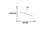
酸素供給制御部54は、例えば、図3に示す酸素供給量マップm01に基づいて、少なくとも始動時T1の最初の酸化剤供給装置30による酸素の供給量を求める。この酸素供給量マップm01は、横軸が酸素濃度、縦軸が酸素供給量を示す。酸素供給量マップm01は、酸素濃度と酸素供給量との関係を記述したものである。この酸素供給量マップm01では、始動時T1の酸化剤供給装置30による酸素の供給量は、酸化剤供給装置30による酸素の供給開始前に酸素濃度センサ52が検出した酸素の濃度、すなわち、循環経路20内に残留していた酸素の濃度の増加にともなって減少する。酸素供給量マップm01は、酸素の供給量と酸素の濃度との関係が始動時に必要な熱量に応じた水素量や環境条件等に基づいて予め設定され、記憶部50bに格納されている。酸素供給制御部54は、この酸素供給量マップm01に基づいて、酸化剤供給装置30による酸素の供給開始前に酸素濃度センサ52が検出した酸素の濃度から、少なくとも始動時T1の最初の酸化剤供給装置30による酸素の供給量を求める。そして、酸素供給制御部54は、この酸化剤供給装置30による酸素の供給開始前の酸素の濃度に応じた始動時の酸化剤供給装置30による酸素の供給量に基づいて、酸化剤供給装置30の酸化剤噴射手段32の駆動を制御し、酸化剤噴射手段32からの酸素の噴射量を制御することで、酸化剤供給装置30からの酸素の供給量を制御する。
For example, the oxygen supply control unit 54 obtains the oxygen supply amount by the first oxidizing agent supply device 30 at least at the start time T1 based on the oxygen supply amount map m01 shown in FIG. In this oxygen supply amount map m01, the horizontal axis indicates the oxygen concentration, and the vertical axis indicates the oxygen supply amount. The oxygen supply amount map m01 describes the relationship between the oxygen concentration and the oxygen supply amount. In this oxygen supply amount map m01, the oxygen supply amount by the oxidant supply device 30 at the start time T1 is the oxygen concentration detected by the oxygen concentration sensor 52 before the oxygen supply start by the oxidant supply device 30, that is, the circulation It decreases as the concentration of oxygen remaining in the path 20 increases. In the oxygen supply amount map m01, the relationship between the oxygen supply amount and the oxygen concentration is set in advance based on the amount of hydrogen corresponding to the amount of heat required at the time of start-up, environmental conditions, and the like, and is stored in the storage unit 50b. Based on the oxygen supply amount map m01, the oxygen supply control unit 54 determines, based on the oxygen concentration detected by the oxygen concentration sensor 52 before starting the oxygen supply by the oxidant supply device 30, at least the first oxidant at the start time T1. The amount of oxygen supplied by the supply device 30 is obtained. Then, the oxygen supply control unit 54 is based on the oxygen supply amount by the oxidant supply device 30 at the start-up according to the oxygen concentration before the oxygen supply start by the oxidant supply device 30. The supply amount of oxygen from the oxidant supply device 30 is controlled by controlling the driving of the oxidant injection unit 32 and controlling the injection amount of oxygen from the oxidant injection unit 32.
なお、本実施形態では、酸素供給制御部54は、酸素供給量マップm01を用いて始動時の酸化剤供給装置30による酸素の供給量を求めたが、本実施形態はこれに限定されない。酸素供給制御部54は、例えば、酸素供給量マップm01に相当する数式に基づいて始動時の酸化剤供給装置30による酸素の供給を求めてもよい。以下で説明する種々のマップについても同様である。
In the present embodiment, the oxygen supply control unit 54 uses the oxygen supply amount map m01 to obtain the oxygen supply amount by the oxidant supply device 30 at the start, but the present embodiment is not limited to this. For example, the oxygen supply control unit 54 may obtain the supply of oxygen by the oxidant supply device 30 at the start based on a mathematical expression corresponding to the oxygen supply amount map m01. The same applies to various maps described below.
この結果、作動ガス循環型エンジン1は、酸素供給制御部54が酸化剤供給装置30による酸素の供給開始前に酸素濃度センサ52が検出した酸素の濃度に基づいて、少なくとも始動時T1の最初の酸化剤供給装置30による酸素の供給量を制御することで、作動ガス循環型エンジン1の停止後の循環経路20内の反応物としての酸素の残留状態にかかわらず始動時に適正な始動性を得ることができる。つまり、作動ガス循環型エンジン1は、作動ガス循環型エンジン1の停止後に循環経路20内に反応物としての酸素が残留している状態で、次の始動時に酸化剤供給装置30による酸素の供給開始前に酸素濃度センサ52が検出した酸素の濃度に応じて少なくとも始動時T1の最初の酸化剤供給装置30による酸素の供給量を増減させることで、通常、始動時に必要とされる酸素の供給量に対して過不足なく燃焼室CCに酸素を供給することができる。したがって、作動ガス循環型エンジン1は、始動時において、燃焼室CC内における反応物としての酸素と作動ガスとの比率が始動時に要求される適正な始動トルクを得ることができる比率からずれることを防止することができ、始動時に要求される適正な始動トルクを得ることができる適正な比率にすることができるので、適正に始動することができる。
As a result, the working gas circulation engine 1 has at least the first start T1 at the start time T1 based on the oxygen concentration detected by the oxygen concentration sensor 52 before the oxygen supply control unit 54 starts supplying oxygen by the oxidant supply device 30. By controlling the amount of oxygen supplied by the oxidant supply device 30, an appropriate startability can be obtained at the start-up regardless of the residual state of oxygen as a reactant in the circulation path 20 after the working gas circulation engine 1 is stopped. be able to. That is, the working gas circulation engine 1 supplies oxygen by the oxidant supply device 30 at the next start-up in a state where oxygen as a reactant remains in the circulation path 20 after the working gas circulation engine 1 is stopped. The supply of oxygen that is normally required at the start-up is usually performed by increasing or decreasing the amount of oxygen supplied by the first oxidant supply device 30 at the start-up time T1 according to the oxygen concentration detected by the oxygen concentration sensor 52 before the start. Oxygen can be supplied to the combustion chamber CC without excess or deficiency with respect to the amount. Therefore, when the working gas circulation engine 1 is started, the ratio of oxygen as the reactant in the combustion chamber CC and the working gas deviates from a ratio at which an appropriate starting torque required at the start can be obtained. It is possible to prevent such a situation, and it is possible to obtain an appropriate ratio at which an appropriate starting torque required at the time of starting can be obtained.
具体的に言えば、作動ガス循環型エンジン1は、酸化剤供給装置30による酸素の供給開始前に酸素濃度センサ52が検出した酸素の濃度が相対的に高いほど、すなわち、循環経路20内に残留している酸素の濃度が相対的に高いほど、酸素供給制御部54が始動時T1の最初の酸化剤供給装置30による酸素の供給量を相対的に少なくすることで、実際に燃焼室CCに供給される酸素の供給量(循環経路20内の残留酸素量と酸化剤供給装置30による酸素供給量との和)が始動時に必要とされる供給量に対して過剰となることを防止することができる。したがって、作動ガス循環型エンジン1は、始動時において、燃焼室CC内に酸素が過剰に供給されることを防止することができることから、燃焼室CC内のアルゴン比率が低下し始動時に要求される適正な始動トルクに対して実際に発生するトルクが不足することを防止することができ、適正に始動することができる。
Specifically, the working gas circulation engine 1 is configured such that the oxygen concentration detected by the oxygen concentration sensor 52 before the start of oxygen supply by the oxidizer supply device 30 is relatively higher, that is, in the circulation path 20. As the concentration of the remaining oxygen is relatively high, the oxygen supply control unit 54 reduces the amount of oxygen supplied by the first oxidant supply device 30 at the start time T1 relatively, thereby actually reducing the combustion chamber CC. The amount of oxygen supplied to the engine (the sum of the amount of residual oxygen in the circulation path 20 and the amount of oxygen supplied by the oxidizer supply device 30) is prevented from becoming excessive with respect to the amount of supply required at the time of starting. be able to. Therefore, since the working gas circulation engine 1 can prevent oxygen from being excessively supplied into the combustion chamber CC at the time of starting, the argon ratio in the combustion chamber CC is reduced and is required at the time of starting. It is possible to prevent a torque actually generated from being insufficient with respect to a proper starting torque, and to start properly.
一方、作動ガス循環型エンジン1は、酸化剤供給装置30による酸素の供給開始前に酸素濃度センサ52が検出した酸素の濃度が相対的に低いほど、すなわち、循環経路20内に残留している酸素の濃度が相対的に低いほど、酸素供給制御部54が始動時T1の最初の酸化剤供給装置30による酸素の供給量を相対的に多くすることで、実際に燃焼室CCに供給される酸素の供給量(循環経路20内の残留酸素量と酸化剤供給装置30による酸素供給量との和)が始動時に必要とされる供給量に対して不足することを防止することができる。したがって、作動ガス循環型エンジン1は、始動時において、燃焼室CC内への酸素の供給が不足することを防止することができることから、燃焼室CC内のアルゴン比率が増加しすぎることを防止することができ、始動時に要求される適正な始動トルクに対して実際に発生するトルクが過剰となることを防止することができ、適正に始動することができる。また、作動ガス循環型エンジン1は、始動時において、燃焼室CC内への酸素の供給が不足することを防止することができることから、水素比率が増加し燃焼室CC内の水素の燃焼に必要な酸素が不足することを防止することができ、始動時に要求される適正な始動トルクに対して実際に発生するトルクが不足することを防止することができ、適正に始動することができると共に、未燃の水素が循環経路20に蓄積されることを防止することができる。
On the other hand, the working gas circulation engine 1 remains in the circulation path 20 as the oxygen concentration detected by the oxygen concentration sensor 52 before the start of oxygen supply by the oxidant supply device 30 is relatively low. As the oxygen concentration is relatively low, the oxygen supply control unit 54 increases the amount of oxygen supplied by the first oxidant supply device 30 at the start time T1 relatively, thereby being actually supplied to the combustion chamber CC. It can be prevented that the supply amount of oxygen (the sum of the residual oxygen amount in the circulation path 20 and the oxygen supply amount by the oxidizer supply device 30) is insufficient with respect to the supply amount required at the time of starting. Accordingly, since the working gas circulation engine 1 can prevent the supply of oxygen into the combustion chamber CC from being insufficient at the time of starting, the argon ratio in the combustion chamber CC is prevented from excessively increasing. Therefore, it is possible to prevent the torque actually generated from being excessive with respect to the appropriate starting torque required at the time of starting, and to start properly. Further, since the working gas circulation engine 1 can prevent the supply of oxygen into the combustion chamber CC from being insufficient at the time of starting, the hydrogen ratio increases and is necessary for combustion of hydrogen in the combustion chamber CC. Insufficient oxygen can be prevented, and it is possible to prevent a torque actually generated from being insufficient with respect to a proper starting torque required at the time of starting. It is possible to prevent unburned hydrogen from accumulating in the circulation path 20.
なお、酸素供給制御部54は、酸化剤供給装置30による酸素の供給開始前に酸素濃度センサ52が検出した酸素の濃度が0である場合、すなわち、作動ガス循環型エンジン1の停止後に循環経路20内に反応物としての酸素が残留していない状態であれば、通常、始動時に必要とされる酸素の供給量がそのまま始動時T1の最初の酸化剤供給装置30による酸素の供給量となる。
Note that the oxygen supply control unit 54 determines the circulation path when the oxygen concentration detected by the oxygen concentration sensor 52 is 0 before the oxygen supply by the oxidant supply device 30 is started, that is, after the working gas circulation engine 1 is stopped. If oxygen as a reactant does not remain in 20, the supply amount of oxygen required at the start is normally the oxygen supply amount by the first oxidant supply device 30 at the start T 1 as it is. .
次に、本実施形態の水素供給制御部55は、燃料供給装置40による水素の供給開始前に水素濃度センサ53が検出した水素の濃度に基づいて、少なくとも始動時T1の最初の燃料供給装置40による水素の供給量を設定する。ここで、燃料供給装置40による水素の供給開始前とは、上述した図2の供給開始時点t2’以前の期間であり、例えば始動開始時点t1以前の期間も含む。つまり燃料供給装置40による水素の供給開始前とは、前回の作動ガス循環型エンジン1の運転が終了し作動ガス循環型エンジン1が停止した時点から供給開始時点t2’までの期間を含む。そして、水素供給制御部55は、供給開始時点t2’以前に水素濃度センサ53が検出した水素の濃度に基づいて少なくとも始動時T1の最初の燃料供給装置40による水素の供給量を設定する。つまり、水素供給制御部55は、作動ガス循環型エンジン1の停止後、次の始動時の供給開始時点までに循環経路20内に残留していた水素の濃度に基づいて、始動時T1の燃料供給装置40による水素の供給量を設定し、供給開始時点t2’にこの設定された供給量で燃料供給装置40により水素を供給する。
Next, the hydrogen supply control unit 55 of the present embodiment, based on the hydrogen concentration detected by the hydrogen concentration sensor 53 before the start of hydrogen supply by the fuel supply device 40, at least the first fuel supply device 40 at the start time T1. Set the hydrogen supply amount. Here, the period before the start of hydrogen supply by the fuel supply device 40 is a period before the supply start time t2 'of FIG. 2 described above, and includes, for example, a period before the start start time t1. That is, the period before the start of hydrogen supply by the fuel supply device 40 includes a period from the time when the previous operation of the working gas circulation engine 1 is completed and the working gas circulation engine 1 is stopped to the supply start time t2 '. Then, the hydrogen supply control unit 55 sets the hydrogen supply amount by the first fuel supply device 40 at least at the start time T1 based on the hydrogen concentration detected by the hydrogen concentration sensor 53 before the supply start time t2 '. That is, the hydrogen supply control unit 55 starts the fuel at the start T1 based on the concentration of hydrogen remaining in the circulation path 20 until the supply start time at the next start after the working gas circulation engine 1 is stopped. The supply amount of hydrogen by the supply device 40 is set, and hydrogen is supplied by the fuel supply device 40 at the set supply amount at the supply start time t2 ′.
なお、水素供給制御部55は、供給開始時点t2’以前に水素濃度センサ53が検出した水素の濃度に基づいて、少なくとも始動時T1の最初の燃料供給装置40による水素の供給量を設定する構成であればよい。水素供給制御部55は、例えば、始動時T1の最初の燃料供給装置40による水素の供給を含む始動時初期の所定回数の燃料供給装置40による水素の供給で、供給開始時点t2’以前に水素濃度センサ53が検出した水素の濃度に基づいて燃料供給装置40による水素の供給量を設定しもよいし、始動時T1の2回目以降の燃料供給装置40による水素の供給では、水素濃度センサ53が検出した現在の水素の濃度に基づいて燃料供給装置40による水素の供給量を設定しもよい。
The hydrogen supply control unit 55 sets the hydrogen supply amount by the fuel supply device 40 at least at the start T1 based on the hydrogen concentration detected by the hydrogen concentration sensor 53 before the supply start time t2 ′. If it is. For example, the hydrogen supply control unit 55 supplies hydrogen by the fuel supply device 40 a predetermined number of times at the beginning of the start including the supply of hydrogen by the first fuel supply device 40 at the start T1, and before the supply start time t2 ′ The supply amount of hydrogen by the fuel supply device 40 may be set based on the concentration of hydrogen detected by the concentration sensor 53. In the supply of hydrogen by the fuel supply device 40 for the second and subsequent times at start T1, the hydrogen concentration sensor 53 may be set. Alternatively, the hydrogen supply amount by the fuel supply device 40 may be set based on the current hydrogen concentration detected by.
水素供給制御部55は、例えば、図4に示す水素供給量マップm02に基づいて、少なくとも始動時T1の最初の燃料供給装置40による水素の供給量を求める。この水素供給量マップm02は、横軸が水素濃度、縦軸が水素供給量を示す。水素供給量マップm02は、水素濃度と水素供給量との関係を記述したものである。この水素供給量マップm02では、始動時T1の燃料供給装置40による水素の供給量は、燃料供給装置40による水素の供給開始前に水素濃度センサ53が検出した水素の濃度、すなわち、循環経路20内に残留していた水素の濃度の増加にともなって減少する。水素供給量マップm02は、水素の供給量と水素の濃度との関係が始動時に必要な熱量に応じた水素量や環境条件等に基づいて予め設定され、記憶部50bに格納されている。水素供給制御部55は、この水素供給量マップm02に基づいて、燃料供給装置40による水素の供給開始前に水素濃度センサ53が検出した水素の濃度から、少なくとも始動時T1の最初の燃料供給装置40による水素の供給量を求める。そして、水素供給制御部55は、この燃料供給装置40による水素の供給開始前の水素の濃度に応じた始動時の燃料供給装置40による水素の供給量に基づいて、燃料供給装置40の燃料噴射手段42の駆動を制御し、燃料噴射手段42からの水素の噴射量を制御することで、燃料供給装置40からの酸素の供給量を制御する。
The hydrogen supply control unit 55 obtains the hydrogen supply amount by the first fuel supply device 40 at least at the start time T1 based on, for example, the hydrogen supply amount map m02 shown in FIG. In this hydrogen supply amount map m02, the horizontal axis indicates the hydrogen concentration, and the vertical axis indicates the hydrogen supply amount. The hydrogen supply amount map m02 describes the relationship between the hydrogen concentration and the hydrogen supply amount. In this hydrogen supply amount map m02, the hydrogen supply amount by the fuel supply device 40 at the start time T1 is the hydrogen concentration detected by the hydrogen concentration sensor 53 before the start of hydrogen supply by the fuel supply device 40, that is, the circulation path 20 It decreases as the concentration of hydrogen remaining inside increases. In the hydrogen supply amount map m02, the relationship between the hydrogen supply amount and the hydrogen concentration is preset based on the amount of hydrogen corresponding to the amount of heat required at the time of start-up, environmental conditions, and the like, and is stored in the storage unit 50b. Based on the hydrogen supply amount map m02, the hydrogen supply control unit 55 determines, based on the hydrogen concentration detected by the hydrogen concentration sensor 53 before starting the hydrogen supply by the fuel supply device 40, at least the first fuel supply device at the start time T1. The amount of hydrogen supplied by 40 is obtained. Then, the hydrogen supply control unit 55 performs fuel injection of the fuel supply device 40 based on the hydrogen supply amount by the fuel supply device 40 at the start-up according to the hydrogen concentration before the hydrogen supply by the fuel supply device 40 starts. The amount of oxygen supplied from the fuel supply device 40 is controlled by controlling the drive of the means 42 and controlling the amount of hydrogen injected from the fuel injection means 42.
この結果、作動ガス循環型エンジン1は、水素供給制御部55が燃料供給装置40による水素の供給開始前に水素濃度センサ53が検出した水素の濃度に基づいて、少なくとも始動時T1の最初の燃料供給装置40による水素の供給量を制御することで、作動ガス循環型エンジン1の停止後の循環経路20内の反応物としての水素の残留状態にかかわらず始動時に適正な始動性を得ることができる。つまり、作動ガス循環型エンジン1は、作動ガス循環型エンジン1の停止後に循環経路20内に反応物としての水素が残留している状態で、次の始動時に燃料供給装置40による水素の供給開始前に水素濃度センサ53が検出した水素の濃度に応じて少なくとも始動時T1の最初の燃料供給装置40による水素の供給量を増減させることで、通常、始動時に必要とされる水素の供給量に対して過不足なく燃焼室CCに水素を供給することができる。したがって、作動ガス循環型エンジン1は、始動時において、燃焼室CC内における反応物としての水素と作動ガスとの比率が始動時に要求される適正な始動トルクを得ることができる比率からずれることを防止することができ、始動時に要求される適正な始動トルクを得ることができる適正な比率にすることができるので、適正に始動することができる。
As a result, the working gas circulation engine 1 has at least the first fuel at the start T1 based on the hydrogen concentration detected by the hydrogen concentration sensor 53 before the hydrogen supply controller 55 starts supplying hydrogen by the fuel supply device 40. By controlling the amount of hydrogen supplied by the supply device 40, an appropriate startability can be obtained at the start-up regardless of the residual state of hydrogen as a reactant in the circulation path 20 after the working gas circulation engine 1 is stopped. it can. That is, the working gas circulation engine 1 starts supplying hydrogen by the fuel supply device 40 at the next start-up in a state where hydrogen as a reactant remains in the circulation path 20 after the working gas circulation engine 1 is stopped. By increasing or decreasing the hydrogen supply amount by the first fuel supply device 40 at least at the start time T1 according to the hydrogen concentration previously detected by the hydrogen concentration sensor 53, the hydrogen supply amount normally required at the start time is increased. On the other hand, hydrogen can be supplied to the combustion chamber CC without excess or deficiency. Therefore, when the working gas circulation engine 1 is started, the ratio of hydrogen as a reactant in the combustion chamber CC to the working gas deviates from a ratio at which an appropriate starting torque required at the start can be obtained. It is possible to prevent such a situation, and it is possible to obtain an appropriate ratio at which an appropriate starting torque required at the time of starting can be obtained.
具体的に言えば、作動ガス循環型エンジン1は、燃料供給装置40による水素の供給開始前に水素濃度センサ53が検出した水素の濃度が相対的に高いほど、すなわち、循環経路20内に残留している水素の濃度が相対的に高いほど、水素供給制御部55が始動時T1の最初の燃料供給装置40による水素の供給量を相対的に少なくすることで、実際に燃焼室CCに供給される水素の供給量(残留水素量+燃料供給装置40による水素供給量)が始動時に必要とされる供給量に対して過剰となることを防止することができる。したがって、作動ガス循環型エンジン1は、始動時において、燃焼室CC内に水素が過剰に供給されることを防止することができることから、燃焼室CC内の水素量が増加し始動時に要求される適正な始動トルクに対して実際に発生するトルクが過剰となることを防止することができ、適正に始動することができる。また、作動ガス循環型エンジン1は、始動時において、燃焼室CC内に水素が過剰に供給されることを防止することができることから、燃焼室CC内のアルゴン比率が低下し始動時に要求される適正な始動トルクに対して実際に発生するトルクが不足することを防止することができ、適正に始動することができる。また、作動ガス循環型エンジン1は、始動時において、燃焼室CC内に水素が過剰に供給されることを防止することができることから、燃焼室CC内の酸素比率が低下し燃焼室CC内の水素の燃焼に必要な酸素が不足することを防止することができ、始動時に要求される適正な始動トルクに対して実際に発生するトルクが不足することを防止することができ、適正に始動することができると共に、未燃の水素が循環経路20に蓄積されることを防止することができる。
Specifically, the working gas circulation engine 1 is more likely to remain in the circulation path 20 as the hydrogen concentration detected by the hydrogen concentration sensor 53 before the supply of hydrogen by the fuel supply device 40 is relatively higher. The higher the concentration of hydrogen that is being supplied, the hydrogen supply control unit 55 actually supplies the combustion chamber CC by reducing the amount of hydrogen supplied by the first fuel supply device 40 at the start time T1. It is possible to prevent the amount of hydrogen supplied (residual hydrogen amount + hydrogen supply amount by the fuel supply device 40) from becoming excessive with respect to the supply amount required at the time of starting. Therefore, since the working gas circulation engine 1 can prevent excessive supply of hydrogen into the combustion chamber CC at the time of starting, the amount of hydrogen in the combustion chamber CC increases and is required at the time of starting. It is possible to prevent an actually generated torque from becoming excessive with respect to an appropriate starting torque, and to start appropriately. Further, since the working gas circulation engine 1 can prevent excessive supply of hydrogen into the combustion chamber CC at the time of starting, the argon ratio in the combustion chamber CC is reduced and is required at the time of starting. It is possible to prevent a torque actually generated from being insufficient with respect to a proper starting torque, and to start properly. In addition, since the working gas circulation engine 1 can prevent excessive supply of hydrogen into the combustion chamber CC at the time of starting, the oxygen ratio in the combustion chamber CC is reduced and the combustion chamber CC has a reduced oxygen ratio. It is possible to prevent a shortage of oxygen necessary for the combustion of hydrogen, and it is possible to prevent a torque that is actually generated from being insufficient with respect to a proper starting torque required at the time of starting, and to start properly. It is possible to prevent unburned hydrogen from accumulating in the circulation path 20.
一方、作動ガス循環型エンジン1は、燃料供給装置40による水素の供給開始前に水素濃度センサ53が検出した水素の濃度が相対的に低いほど、すなわち、循環経路20内に酸素が残留している水素の濃度が相対的に低いほど、水素供給制御部55が始動時T1の最初の燃料供給装置40による水素の供給量を相対的に多くすることで、実際に燃焼室CCに供給される水素の供給量(残留水素量+燃料供給装置40による水素供給量)が始動時に必要とされる供給量に対して不足することを防止することができる。したがって、作動ガス循環型エンジン1は、始動時において、燃焼室CC内への水素の供給が不足することを防止することができることから、燃焼室CC内の水素量が低下し始動時に要求される適正な始動トルクに対して実際に発生するトルクが不足することを防止することができ、適正に始動することができる。また、作動ガス循環型エンジン1は、始動時において、燃焼室CC内への水素の供給が不足することを防止することができることから、燃焼室CC内のアルゴン比率が増加しすぎることを防止することができ、始動時に要求される適正な始動トルクに対して実際に発生するトルクが過剰となることを防止することができ、適正に始動することができる。
On the other hand, in the working gas circulation engine 1, the lower the hydrogen concentration detected by the hydrogen concentration sensor 53 before the start of hydrogen supply by the fuel supply device 40, that is, oxygen remains in the circulation path 20. The hydrogen supply control unit 55 relatively increases the amount of hydrogen supplied by the first fuel supply device 40 at the start time T1, so that the hydrogen is actually supplied to the combustion chamber CC. It is possible to prevent the hydrogen supply amount (residual hydrogen amount + hydrogen supply amount by the fuel supply device 40) from being insufficient with respect to the supply amount required at the time of starting. Therefore, since the working gas circulation engine 1 can prevent the supply of hydrogen into the combustion chamber CC from being insufficient at the time of starting, the amount of hydrogen in the combustion chamber CC is reduced and is required at the time of starting. It is possible to prevent a torque actually generated from being insufficient with respect to a proper starting torque, and to start properly. Further, since the working gas circulation engine 1 can prevent the supply of hydrogen into the combustion chamber CC from being insufficient at the time of starting, the argon ratio in the combustion chamber CC is prevented from excessively increasing. Therefore, it is possible to prevent the torque actually generated from being excessive with respect to the appropriate starting torque required at the time of starting, and to start properly.
なお、水素供給制御部55は、燃料供給装置40による水素の供給開始前に水素濃度センサ53が検出した水素の濃度が0である場合、すなわち、作動ガス循環型エンジン1の停止後に循環経路20内に反応物としての水素が残留していない状態であれば、通常、始動時に必要とされる水素の供給量がそのまま始動時T1の最初の燃料供給装置40による水素の供給量となる。
Note that the hydrogen supply control unit 55 is configured so that the hydrogen concentration detected by the hydrogen concentration sensor 53 before the hydrogen supply by the fuel supply device 40 is zero, that is, the circulation path 20 after the working gas circulation engine 1 is stopped. If no hydrogen remains as a reactant, the hydrogen supply amount required at the time of start is normally the hydrogen supply amount by the first fuel supply device 40 at the start time T1.
次に、図5のフローチャートを参照して本実施形態に係る作動ガス循環型エンジン1の始動時の酸素供給制御を説明する。なお、この始動時の酸素供給制御は、作動ガス循環型エンジン1の始動制御で実行される制御であり、基本的には始動開始時点t1から始動終了時点t4まで実行される。また、この制御ルーチンは、数msないし数十ms毎の制御周期で繰り返し実行される。なお、本図で説明する酸素供給制御は、基本的には始動時T1の最初の酸素供給の酸素供給制御である。
Next, oxygen supply control at the start of the working gas circulation engine 1 according to this embodiment will be described with reference to the flowchart of FIG. The oxygen supply control at the time of starting is a control executed by the starting control of the working gas circulation engine 1, and is basically executed from the starting start time t1 to the starting end time t4. Further, this control routine is repeatedly executed at a control cycle every several ms to several tens of ms. The oxygen supply control described in this figure is basically the oxygen supply control of the first oxygen supply at the start time T1.
まず、電子制御装置50の始動状態判定部56は、クランク角センサ51の検出信号に基づいて作動ガス循環型エンジン1のエンジン回転数を取得し、このエンジン回転数に基づいて作動ガス循環型エンジン1が始動時であるか否を判定する(S100)。始動状態判定部56は、エンジン回転数が予め設定される所定のエンジン回転数より高いか否かに基づいて作動ガス循環型エンジン1が始動時であるか否を判定する。
First, the starting state determination unit 56 of the electronic control unit 50 acquires the engine speed of the working gas circulation engine 1 based on the detection signal of the crank angle sensor 51, and the working gas circulation engine based on the engine speed. It is determined whether 1 is a start time (S100). The starting state determination unit 56 determines whether or not the working gas circulation engine 1 is in a starting state based on whether or not the engine speed is higher than a predetermined engine speed set in advance.
電子制御装置50は、始動状態判定部56により作動ガス循環型エンジン1が始動時でないと判定された場合(S100:No)、つまり、作動ガス循環型エンジン1が始動後であると判定された場合、この制御周期を終了し、次の制御周期に移行すると共に、例えば、通常の酸素供給制御を実行する。
The electronic control unit 50 determines that the working gas circulation engine 1 has not been started by the starting state determination unit 56 (S100: No), that is, the working gas circulation engine 1 has been judged to have been started. In this case, the control cycle is terminated and the next control cycle is started, and, for example, normal oxygen supply control is executed.
始動状態判定部56は、作動ガス循環型エンジン1が始動時であると判定した場合(S100:Yes)、酸化剤供給装置30による酸素の供給開始前(初回の酸素の供給開始前)であるか否かを判定する(S101)。
When it is determined that the working gas circulation engine 1 is at the time of starting (S100: Yes), the starting state determination unit 56 is before starting the supply of oxygen by the oxidant supply device 30 (before starting the first supply of oxygen). It is determined whether or not (S101).
電子制御装置50は、始動状態判定部56により酸化剤供給装置30による酸素の供給開始後であると判定された場合(S101:No)、この制御周期を終了し、次の制御周期に移行すると共に、例えば、2回目以降の酸素供給制御を実行する。
When it is determined by the starting state determination unit 56 that the supply of oxygen by the oxidant supply device 30 has been started (S101: No), the electronic control device 50 ends this control cycle and shifts to the next control cycle. At the same time, for example, the second and subsequent oxygen supply control is executed.
酸素供給制御部54は、始動状態判定部56により酸化剤供給装置30による酸素の供給開始前と判定された場合(S101:Yes)、酸素濃度センサ52が検出した酸素の濃度(酸化剤供給装置30による酸素の供給開始前の循環経路20内の酸素濃度)を取得する(S102)。
The oxygen supply control unit 54 determines the oxygen concentration (oxidant supply device) detected by the oxygen concentration sensor 52 when the start state determination unit 56 determines that oxygen supply is not started by the oxidant supply device 30 (S101: Yes). The oxygen concentration in the circulation path 20 before starting the supply of oxygen by 30 is acquired (S102).
次に、酸素供給制御部54は、例えば、酸素供給量マップm01に基づいて、S102で取得した酸化剤供給装置30による酸素の供給開始前の酸素の濃度から始動時の最初の酸化剤供給装置30による酸素の供給量を算出する。(S103)。
Next, the oxygen supply control unit 54, for example, based on the oxygen supply amount map m01, the first oxidant supply device at the time of start-up from the oxygen concentration before the start of oxygen supply by the oxidant supply device 30 acquired in S102. The amount of oxygen supplied by 30 is calculated. (S103).
次に、酸素供給制御部54は、現在が酸素の供給時期であるか否かを判定する(S104)。酸素供給制御部54は、例えば、クランク角センサ51の検出結果より、作動ガス循環型エンジン1が吸気行程、圧縮行程、燃焼行程、排気行程のうち、どの行程であるかを判断し、この判断に基づいて、現在が酸化剤供給装置30による酸素の供給時期であるか否かを判定する。酸素供給制御部54は、例えば、作動ガス循環型エンジン1の現在の行程が吸気行程、あるいは吸気行程の直前である場合に酸化剤供給装置30による酸素の供給時期であると判定する。
Next, the oxygen supply control unit 54 determines whether or not the present time is the supply timing of oxygen (S104). For example, the oxygen supply control unit 54 determines, based on the detection result of the crank angle sensor 51, which stroke of the intake gas stroke, the compression stroke, the combustion stroke, and the exhaust stroke the working gas circulation engine 1 is. Based on the above, it is determined whether or not the present time is the supply timing of oxygen by the oxidant supply device 30. For example, when the current stroke of the working gas circulation engine 1 is the intake stroke or immediately before the intake stroke, the oxygen supply control unit 54 determines that it is the oxygen supply timing by the oxidant supply device 30.
電子制御装置50は、酸素供給制御部54により現在が酸素の供給時期でないと判定された場合(S104:No)、この制御周期を終了し、次の制御周期に移行する。
When the oxygen supply control unit 54 determines that the current time is not the oxygen supply timing (S104: No), the electronic control unit 50 ends this control cycle and shifts to the next control cycle.
酸素供給制御部54は、現在が酸素の供給時期であると判定した場合(S104:Yes)、S103で酸化剤供給装置30による酸素の供給開始前の酸素の濃度に応じて算出した酸化剤供給装置30による酸素の供給量に基づいて、酸化剤供給装置30の酸化剤噴射手段32の駆動を制御し、酸化剤噴射手段32からの酸素の噴射量を制御することで、酸化剤供給装置30からの酸素の供給量を制御し(S105)、この制御周期を終了し、次の制御周期に移行する。
If the oxygen supply control unit 54 determines that the current time is the oxygen supply timing (S104: Yes), the oxidant supply calculated in S103 according to the oxygen concentration before the oxygen supply by the oxidant supply device 30 is started. The oxidant supply device 30 is controlled by controlling the driving of the oxidant injection means 32 of the oxidant supply device 30 and controlling the injection amount of oxygen from the oxidant injection means 32 based on the supply amount of oxygen by the device 30. The amount of oxygen supplied from is controlled (S105), this control cycle is terminated, and the next control cycle is started.
次に、図6のフローチャートを参照して本実施形態に係る作動ガス循環型エンジン1の始動時の水素供給制御を説明する。なお、この始動時の水素供給制御は、作動ガス循環型エンジン1の始動制御で実行される制御であり、基本的には始動開始時点t1から始動終了時点t4まで実行される。また、この制御ルーチンは、数msないし数十ms毎の制御周期で繰り返し実行される。なお、本図で説明する水素供給制御は、基本的には始動時T1の最初の水素供給の水素供給制御である。
Next, hydrogen supply control at the start of the working gas circulation engine 1 according to the present embodiment will be described with reference to the flowchart of FIG. The hydrogen supply control at the time of starting is a control executed by the starting control of the working gas circulation engine 1 and is basically executed from the starting start time t1 to the starting end time t4. Further, this control routine is repeatedly executed at a control cycle every several ms to several tens of ms. The hydrogen supply control described in this figure is basically the hydrogen supply control of the first hydrogen supply at the start time T1.
まず、電子制御装置50の始動状態判定部56は、クランク角センサ51の検出信号に基づいて作動ガス循環型エンジン1のエンジン回転数を取得し、このエンジン回転数に基づいて作動ガス循環型エンジン1が始動時であるか否を判定する(S200)。
First, the starting state determination unit 56 of the electronic control unit 50 acquires the engine speed of the working gas circulation engine 1 based on the detection signal of the crank angle sensor 51, and the working gas circulation engine based on the engine speed. It is determined whether 1 is a start time (S200).
電子制御装置50は、始動状態判定部56により作動ガス循環型エンジン1が始動時でないと判定された場合(S200:No)、つまり、作動ガス循環型エンジン1が始動後であると判定された場合、この制御周期を終了し、次の制御周期に移行すると共に、例えば、通常の水素供給制御を実行する。
The electronic control unit 50 determines that the working gas circulation engine 1 has not been started by the starting state determination unit 56 (S200: No), that is, the working gas circulation engine 1 has been judged to have been started. In this case, the control cycle is terminated and the next control cycle is started, and, for example, normal hydrogen supply control is executed.
始動状態判定部56は、作動ガス循環型エンジン1が始動時であると判定した場合(S200:Yes)、燃料供給装置40による水素の供給開始前(初回の水素の供給開始前)であるか否かを判定する(S201)。
When the starting state determination unit 56 determines that the working gas circulation engine 1 is at the time of starting (S200: Yes), is the start of hydrogen supply by the fuel supply device 40 (before the first hydrogen supply start)? It is determined whether or not (S201).
電子制御装置50は、始動状態判定部56により燃料供給装置40による水素の供給開始後であると判定された場合(S201:No)、この制御周期を終了し、次の制御周期に移行すると共に、例えば、2回目以降の水素供給制御を実行する。
When it is determined by the starting state determination unit 56 that the supply of hydrogen by the fuel supply device 40 has started (S201: No), the electronic control device 50 ends this control cycle and shifts to the next control cycle. For example, the second and subsequent hydrogen supply control is executed.
水素供給制御部55は、始動状態判定部56により燃料供給装置40による水素の供給開始前と判定された場合(S201:Yes)、水素濃度センサ53が検出した水素の濃度(燃料供給装置40による水素の供給開始前の循環経路20内の水素濃度)を取得する(S202)。
The hydrogen supply control unit 55 determines the hydrogen concentration detected by the hydrogen concentration sensor 53 (depending on the fuel supply device 40) when the start state determination unit 56 determines that hydrogen supply is not started by the fuel supply device 40 (S201: Yes). The hydrogen concentration in the circulation path 20 before the start of hydrogen supply is acquired (S202).
次に、水素供給制御部55は、例えば、水素供給量マップm02に基づいて、S202で取得した燃料供給装置40による水素の供給開始前の水素の濃度から始動時の最初の燃料供給装置40による水素の供給量を算出する。(S203)。
Next, for example, based on the hydrogen supply amount map m02, the hydrogen supply control unit 55 uses the initial fuel supply device 40 at the time of starting from the hydrogen concentration before the start of hydrogen supply by the fuel supply device 40 acquired in S202. Calculate the hydrogen supply. (S203).
次に、水素供給制御部55は、現在が水素の供給時期であるか否かを判定する(S204)。水素供給制御部55は、例えば、クランク角センサ51の検出結果より、作動ガス循環型エンジン1が吸気行程、圧縮行程、燃焼行程、排気行程のうち、どの行程であるかを判断し、この判断に基づいて、現在が燃料供給装置40による水素の供給時期であるか否かを判定する。水素供給制御部55は、例えば、作動ガス循環型エンジン1の現在の行程が燃焼行程、あるいは燃焼行程の直前である場合に燃料供給装置40による水素の供給時期であると判定する。
Next, the hydrogen supply control unit 55 determines whether or not the present time is the supply timing of hydrogen (S204). For example, the hydrogen supply control unit 55 determines, based on the detection result of the crank angle sensor 51, which stroke of the intake gas stroke, the compression stroke, the combustion stroke, and the exhaust stroke the working gas circulation engine 1 is. Based on the above, it is determined whether or not the present time is the supply timing of hydrogen by the fuel supply device 40. For example, when the current stroke of the working gas circulation engine 1 is the combustion stroke or immediately before the combustion stroke, the hydrogen supply control unit 55 determines that it is the supply timing of hydrogen by the fuel supply device 40.
電子制御装置50は、水素供給制御部55により現在が水素の供給時期でないと判定された場合(S204:No)、この制御周期を終了し、次の制御周期に移行する。
When it is determined by the hydrogen supply control unit 55 that the present time is not the hydrogen supply timing (S204: No), the electronic control unit 50 ends this control cycle and shifts to the next control cycle.
水素供給制御部55は、現在が水素の供給時期であると判定した場合(S204:Yes)、S203で燃料供給装置40による水素の供給開始前の水素の濃度に応じて算出した燃料供給装置40による水素の供給量に基づいて、燃料供給装置40の燃料噴射手段42の駆動を制御し、燃料噴射手段42からの水素の噴射量を制御することで、燃料供給装置40からの水素の供給量を制御し(S205)、この制御周期を終了し、次の制御周期に移行する。
When the hydrogen supply control unit 55 determines that the current time is the hydrogen supply time (S204: Yes), the fuel supply device 40 calculated in accordance with the hydrogen concentration before the start of hydrogen supply by the fuel supply device 40 in S203. The amount of hydrogen supplied from the fuel supply unit 40 is controlled by controlling the drive of the fuel injection unit 42 of the fuel supply unit 40 and the amount of hydrogen injection from the fuel injection unit 42 based on the amount of hydrogen supplied by (S205), this control cycle is terminated, and the process proceeds to the next control cycle.
以上で説明した本発明の実施形態に係る作動ガス循環型エンジン1によれば、反応物と、空気より比熱比の高い作動ガスとが供給され、反応物の反応に伴って作動ガスが膨張可能である燃焼室CCと、作動ガスを燃焼室CCの排気側から吸気側に循環させ再び燃焼室CCに供給可能な循環経路20と、反応物を供給する供給装置2と、循環経路内の反応物の濃度を検出可能な反応物濃度センサ3と、供給装置2による反応物の供給開始前に反応物濃度センサ3が検出した反応物の濃度に基づいて、少なくとも始動時T1の最初の供給装置2による反応物の供給量を設定する供給制御部4とを備える。
According to the working gas circulation engine 1 according to the embodiment of the present invention described above, the reactant and the working gas having a higher specific heat ratio than air are supplied, and the working gas can expand as the reactant reacts. The combustion chamber CC, the circulation path 20 through which the working gas is circulated from the exhaust side to the intake side of the combustion chamber CC and can be supplied again to the combustion chamber CC, the supply device 2 for supplying reactants, and the reaction in the circulation path A reactant concentration sensor 3 capable of detecting the concentration of the substance, and the first supply device at least at the start time T1 based on the concentration of the reactant detected by the reactant concentration sensor 3 before the supply of the reactant by the supply device 2 is started. 2 and a supply control unit 4 for setting the supply amount of the reactants.
したがって、作動ガス循環型エンジン1は、供給制御部4が供給装置2による反応物の供給開始前に反応物濃度センサ3が検出した反応物の濃度に基づいて、少なくとも始動時T1の最初の供給装置2による反応物の供給量を制御することで、前回の作動ガス循環型エンジン1の停止後の循環経路20内の反応物の残留状態にかかわらず、通常、始動時に必要とされる反応物の供給量に対して過不足なく燃焼室CCに反応物を供給することができ、始動時において、燃焼室CC内における反応物と作動ガスとの比率を始動時に要求される適正な始動トルクを得ることができる適正な比率にすることができるので、適正に始動することができる。
Therefore, in the working gas circulation engine 1, the supply controller 4 supplies at least the first supply at the start time T1 based on the concentration of the reactant detected by the reactant concentration sensor 3 before the supply of the reactant by the supply device 2 is started. By controlling the amount of reactant supplied by the device 2, the reactant that is normally required at the start-up, regardless of the residual state of the reactant in the circulation path 20 after the previous stoppage of the working gas circulation engine 1 The reactant can be supplied to the combustion chamber CC without excess or deficiency with respect to the supply amount of the gas, and at the time of starting, the ratio of the reactant to the working gas in the combustion chamber CC is set to an appropriate starting torque required at the time of starting. Since the proper ratio can be obtained, it is possible to start properly.
さらに、以上で説明した本発明の実施形態に係る作動ガス循環型エンジン1によれば、供給装置2は、反応物として酸素を供給し、反応物濃度センサ3は、酸素の濃度を検出可能であり、供給制御部4は、供給装置2による酸素の供給開始前に反応物濃度センサ3が検出した酸素の濃度に基づいて、少なくとも始動時の最初の供給装置2による酸素の供給量を設定する。したがって、供給制御部4が供給装置2による酸素の供給開始前に反応物濃度センサ3が検出した酸素の濃度に基づいて、少なくとも始動時T1の最初の供給装置2による酸素の供給量を制御することで、前回の作動ガス循環型エンジン1の停止後の循環経路20内の酸素の残留状態にかかわらず、通常、始動時に必要とされる酸素の供給量に対して過不足なく燃焼室CCに酸素を供給することができ、始動時において、燃焼室CC内における酸素と作動ガスとの比率を始動時に要求される適正な始動トルクを得ることができる適正な比率にすることができるので、適正に始動することができる。
Furthermore, according to the working gas circulation engine 1 according to the embodiment of the present invention described above, the supply device 2 supplies oxygen as a reactant, and the reactant concentration sensor 3 can detect the concentration of oxygen. Yes, the supply control unit 4 sets at least the amount of oxygen supplied by the supply device 2 at the time of start-up based on the oxygen concentration detected by the reactant concentration sensor 3 before the supply of oxygen by the supply device 2 is started. . Accordingly, the supply control unit 4 controls the oxygen supply amount by the first supply device 2 at least at the start time T1 based on the oxygen concentration detected by the reactant concentration sensor 3 before the supply of oxygen by the supply device 2 is started. Thus, regardless of the remaining state of oxygen in the circulation path 20 after the previous stoppage of the working gas circulation engine 1, the oxygen supply amount normally required at the start is not excessively and insufficiently set in the combustion chamber CC. Oxygen can be supplied, and at the time of start-up, the ratio of oxygen and working gas in the combustion chamber CC can be set to an appropriate ratio that can obtain an appropriate start-up torque required at start-up. Can be started.
さらに、以上で説明した本発明の実施形態に係る作動ガス循環型エンジン1によれば、供給装置2は、反応物として水素を供給し、反応物濃度センサ3は、水素の濃度を検出可能であり、供給制御部4は、供給装置2による水素の供給開始前に反応物濃度センサ3が検出した水素の濃度に基づいて、少なくとも始動時T1の最初の供給装置2による水素の供給量を設定する。したがって、供給制御部4が供給装置2による水素の供給開始前に反応物濃度センサ3が検出した水素の濃度に基づいて、少なくとも始動時T1の最初の供給装置2による水素の供給量を制御することで、前回の作動ガス循環型エンジン1の停止後の循環経路20内の水素の残留状態にかかわらず、通常、始動時に必要とされる水素の供給量に対して過不足なく燃焼室CCに酸素を供給することができ、始動時において、燃焼室CC内における水素と作動ガスとの比率を始動時に要求される適正な始動トルクを得ることができる適正な比率にすることができるので、適正に始動することができる。
Furthermore, according to the working gas circulation engine 1 according to the embodiment of the present invention described above, the supply device 2 supplies hydrogen as a reactant, and the reactant concentration sensor 3 can detect the concentration of hydrogen. Yes, the supply control unit 4 sets the hydrogen supply amount by the first supply device 2 at least at the start T1 based on the hydrogen concentration detected by the reactant concentration sensor 3 before the supply of hydrogen by the supply device 2 is started. To do. Therefore, the supply control unit 4 controls the hydrogen supply amount by the first supply device 2 at least at the start T1 based on the hydrogen concentration detected by the reactant concentration sensor 3 before the supply device 2 starts supplying hydrogen. Thus, regardless of the remaining state of hydrogen in the circulation path 20 after the previous stoppage of the working gas circulation engine 1, the hydrogen supply amount normally required at the start is not excessively and insufficiently set in the combustion chamber CC. Oxygen can be supplied, and at the time of start-up, the ratio of hydrogen and working gas in the combustion chamber CC can be set to an appropriate ratio that can obtain the proper start-up torque required at start-up. Can be started.
さらに、以上で説明した本発明の実施形態に係る作動ガス循環型エンジン1によれば、供給制御部4は、反応物が複数ある場合、すなわち、反応物として酸素と水素とがある場合は、各々の反応物、すなわち、酸素、水素それぞれに対して、供給装置2による酸素、水素の各々の供給開始前に反応物濃度センサ3が検出した各々の酸素、水素の濃度に基づいて、少なくとも始動時T1の最初の供給装置2による酸素、水素の供給量を各々設定する。したがって、作動ガス循環型エンジン1は、反応物が複数ある場合、すなわち、反応物として、酸化剤としての酸素と燃料としての水素が用いられる場合であっても、より正確に燃焼室CC内での反応物、すなわち酸素、水素と作動ガスとの比率を始動時に要求される適正な始動トルクを得ることができる適正な比率にすることができ、適正に始動することができる。
Furthermore, according to the working gas circulation engine 1 according to the embodiment of the present invention described above, the supply control unit 4 has a plurality of reactants, that is, when there are oxygen and hydrogen as reactants, For each of the reactants, that is, oxygen and hydrogen, respectively, start at least based on the concentrations of the oxygen and hydrogen detected by the reactant concentration sensor 3 before the supply of oxygen and hydrogen by the supply device 2 is started. The supply amounts of oxygen and hydrogen by the first supply device 2 at time T1 are set. Therefore, the working gas circulation engine 1 is more accurate in the combustion chamber CC even when there are a plurality of reactants, that is, when oxygen as an oxidizer and hydrogen as a fuel are used as reactants. The ratio of the reactants, that is, oxygen, hydrogen, and the working gas can be set to an appropriate ratio capable of obtaining an appropriate starting torque required at the time of starting, and the starting can be appropriately performed.
なお、以上の説明では、供給制御部4は、反応物としての酸素、水素それぞれに対して、供給装置2による酸素、水素の各々の供給開始前に反応物濃度センサ3が検出した各々の酸素、水素の濃度に基づいて、少なくとも始動時T1の最初の供給装置2による酸素、水素の供給量を各々設定するものとして説明したが、これに限らず、必ずしも全ての反応物に対して、供給開始前の濃度に基づいて始動時T1の最初の供給装置2による供給量を設定する必要はない。供給制御部4は、例えば作動ガス循環型エンジン1の停止直前の運転状態において、循環経路20内に酸素と水素のいずれか一方しか残留することがないように運転していたような場合には、当該一方の反応物に対してのみ供給開始前の濃度に基づいて始動時T1の最初の供給装置2による供給量を設定するようにしてもよく、この場合であっても、作動ガス循環型エンジン1は、始動時において、燃焼室CC内における反応物と作動ガスとの比率を始動時に要求される適正な始動トルクを得ることができる適正な比率にすることができるので、適正に始動することができる。
In the above description, the supply control unit 4 detects each oxygen detected by the reactant concentration sensor 3 before starting the supply of oxygen and hydrogen by the supply device 2 for each of oxygen and hydrogen as reactants. In the above description, the oxygen and hydrogen supply amounts of the first supply device 2 at least at the start time T1 are set based on the hydrogen concentration, respectively. However, the present invention is not limited to this. It is not necessary to set the supply amount by the first supply device 2 at the start time T1 based on the concentration before the start. For example, the supply control unit 4 is operated so that only one of oxygen and hydrogen remains in the circulation path 20 in the operation state immediately before the working gas circulation engine 1 is stopped. The supply amount by the first supply device 2 at the start time T1 may be set based on the concentration before the start of supply only for the one reactant, even in this case, the working gas circulation type The engine 1 can start properly because the ratio of the reactant and the working gas in the combustion chamber CC can be set to an appropriate ratio that can obtain an appropriate starting torque required at the time of starting. be able to.
(実施形態2)
図7は、本発明の実施形態2に係る作動ガス循環型エンジンの始動時の酸素・水素供給制御を説明するフローチャートである。実施形態2に係る作動ガス循環型エンジンは、実施形態1に係る作動ガス循環型エンジンと略同様の構成であるが始動時初期の酸素供給手段による酸素の供給量を燃焼後のガス中に酸素が残留する供給量に設定する点で実施形態1に係る作動ガス循環型エンジンとは異なる。その他、上述した実施形態と共通する構成、作用、効果については、重複した説明はできるだけ省略するとともに、同一の符号を付す。また、実施形態2に係る作動ガス循環型エンジンの各構成については、図1等を参照する。(Embodiment 2)
FIG. 7 is a flowchart for explaining oxygen / hydrogen supply control at the start of the working gas circulation engine according to the second embodiment of the present invention. The working gas circulation engine according to the second embodiment has substantially the same configuration as that of the working gas circulation engine according to the first embodiment. However, the amount of oxygen supplied by the oxygen supply means at the initial stage of startup is changed to oxygen in the gas after combustion. Is different from the working gas circulation engine according to the first embodiment in that the remaining supply amount is set. In addition, about the structure, effect | action, and effect which are common in embodiment mentioned above, while overlapping description is abbreviate | omitted as much as possible, the same code | symbol is attached | subjected. For each configuration of the working gas circulation engine according to the second embodiment, refer to FIG.
本実施形態の作動ガス循環型エンジン201は、供給制御部4をなす酸素供給制御部54が始動時初期の酸化剤供給装置30による酸素の供給量を酸化剤供給装置30による酸素の供給開始前に酸素濃度センサ52が検出した酸素の濃度に基づいて、燃焼後のガス中に酸素が残留する供給量に設定する。ここでいう始動時初期とは、始動時T1の初期の期間であって、少なくとも始動時T1の最初の酸化剤供給装置30による酸素の供給を含む期間、さら言えば、少なくとも始動時T1の最初の酸化剤供給装置30による酸素の供給から予め設定される所定回数の酸素の供給が終わるまでの期間である。
In the working gas circulation engine 201 according to the present embodiment, the oxygen supply control unit 54 constituting the supply control unit 4 sets the oxygen supply amount by the oxidant supply device 30 at the initial stage of start-up before the oxygen supply by the oxidant supply device 30 starts. Based on the concentration of oxygen detected by the oxygen concentration sensor 52, the supply amount at which oxygen remains in the burned gas is set. The initial start-up time here is an initial period of the start-up time T1, which is at least a period including the supply of oxygen by the first oxidant supply device 30 at the start-up time T1, more specifically, at least the first start-up time T1. This is a period from the supply of oxygen by the oxidant supply device 30 to the end of a predetermined number of oxygen supplies set in advance.
ところで、この作動ガス循環型エンジン201は、上述したように、供給装置2が酸化剤供給装置30と燃料供給装置40とを含んで構成される。酸化剤供給装置30は、反応物として酸素を循環経路20に供給して燃焼室CCに供給する。すなわち、酸化剤供給装置30は、酸化剤噴射手段32が酸素を吸気ポート11bに噴射することで、この酸素を吸気ポート11bの作動ガスと混ぜ合わせて燃焼室CCに供給する。燃料供給装置40は、反応物として酸素によって燃焼する水素を燃焼室CCに直接供給する。すなわち、燃料供給装置40は、燃料噴射手段42が水素を燃焼室CCに噴射することで、この水素を燃焼室CCに直接供給する。
By the way, the working gas circulation engine 201 is configured such that the supply device 2 includes the oxidant supply device 30 and the fuel supply device 40 as described above. The oxidant supply device 30 supplies oxygen as a reactant to the circulation path 20 and supplies it to the combustion chamber CC. That is, the oxidant supply device 30 causes the oxidant injection means 32 to inject oxygen into the intake port 11b, and mixes this oxygen with the working gas in the intake port 11b and supplies it to the combustion chamber CC. The fuel supply device 40 directly supplies hydrogen, which is burned by oxygen as a reactant, to the combustion chamber CC. That is, the fuel supply device 40 directly supplies the hydrogen to the combustion chamber CC by the fuel injection means 42 injecting the hydrogen into the combustion chamber CC.
ここで、この作動ガス循環型エンジン201では、燃料供給装置40によって燃焼室CCに直接供給される水素は、燃料供給装置40から供給された水素の全てが始動時初期においても常に遅れもなく燃焼室CCに供給される。一方、酸化剤供給装置30によって燃焼室CCの外部、すなわち、吸気弁15を挟んで燃焼室CCとは反対側の吸気ポート11bに噴射され燃焼室CCに供給される酸素は、作動ガス循環型エンジン201の停止状態からの最初の吸気行程では前回のサイクルでの酸素供給がなく、1回の吸気行程で燃焼室CCに吸入可能な吸入量が限られており、また、吸気弁15の開閉タイミングの影響も受けることから、始動時初期において燃焼室CCに吸入されにくくなる傾向になり、必ずしも酸化剤供給装置30から吸気ポート11bに供給された酸素の全てが燃焼室CCに吸入されるとは限らない場合がある。つまり、この作動ガス循環型エンジン201では、始動時初期において、始動時に要求される適正な始動トルクを発生させるための燃焼室CCへの水素の供給量に対して、実際に燃焼室CCに供給される酸素の供給量が酸化剤供給装置30から吸気ポート11bに供給された酸素の一部がこの吸気ポート11bに残留することで不足し、すなわち、実際に燃焼室CCに供給される酸素の供給量が燃焼室CCに供給された水素を全て燃焼させるために必要な酸素供給量に対して不足し、この結果、始動時に要求される適正な始動トルクに対して実際に発生するトルクが不足しスムーズな始動ができなかったり未燃の水素が循環経路20に蓄積されたりおそれがある。
Here, in this working gas circulation engine 201, the hydrogen supplied directly to the combustion chamber CC by the fuel supply device 40 is always combusted without delay even in the initial stage of starting all of the hydrogen supplied from the fuel supply device 40. Supplied to chamber CC. On the other hand, the oxygen supplied to the combustion chamber CC by being injected into the outside of the combustion chamber CC, that is, the intake port 11b on the opposite side of the combustion chamber CC across the intake valve 15 by the oxidant supply device 30 is a working gas circulation type. In the first intake stroke from the stop state of the engine 201, there is no oxygen supply in the previous cycle, the intake amount that can be drawn into the combustion chamber CC in one intake stroke is limited, and the intake valve 15 is opened and closed Since it is also influenced by the timing, it tends to be difficult to be sucked into the combustion chamber CC at the initial stage of start-up, and when all of the oxygen supplied from the oxidant supply device 30 to the intake port 11b is sucked into the combustion chamber CC. May not always be the case. That is, in this working gas circulation engine 201, in the initial stage of start-up, the hydrogen supply amount to the combustion chamber CC for generating an appropriate start-up torque required at the start is actually supplied to the combustion chamber CC. The amount of oxygen supplied is insufficient because a part of the oxygen supplied from the oxidizer supply device 30 to the intake port 11b remains in the intake port 11b, that is, the amount of oxygen actually supplied to the combustion chamber CC. The supply amount is insufficient with respect to the oxygen supply amount necessary for burning all the hydrogen supplied to the combustion chamber CC, and as a result, the torque actually generated is insufficient with respect to the proper starting torque required at the start. However, there is a possibility that the engine cannot be started smoothly or unburned hydrogen is accumulated in the circulation path 20.
そこで、本実施形態の作動ガス循環型エンジン201は、上述したように、供給制御部4をなす酸素供給制御部54が始動時初期の酸化剤供給装置30による酸素の供給量を水素と酸素との燃焼後のガス中に酸素が残留する供給量に増量して設定することで、始動時に要求される適正な始動トルクに対して実際に発生するトルクが不足することを防止し適正な始動の実現を図ると共に未燃水素が循環経路20に蓄積されることを防止している。
Therefore, in the working gas circulation engine 201 of the present embodiment, as described above, the oxygen supply control unit 54 constituting the supply control unit 4 sets the supply amount of oxygen by the oxidant supply device 30 at the initial stage of startup to hydrogen and oxygen. The amount of oxygen remaining in the gas after combustion is increased and set to prevent the torque that is actually generated from running short of the proper starting torque required at the start. This achieves realization and prevents unburned hydrogen from accumulating in the circulation path 20.
つまり、作動ガス循環型エンジン201は、始動時初期において酸化剤供給装置30から吸気ポート11bに供給する酸素の供給量を燃焼室CCへの水素の供給量に対する理論割合よりも増量することで、始動時初期において酸素が燃焼室CCに吸入されにくい状態であり酸化剤供給装置30から吸気ポート11bに供給された酸素の一部が吸気ポート11bに残留し全てが燃焼室CCに吸入されない状態であっても、水素を全て燃焼させるのに十分な量の酸素を燃焼室CCに供給することができる。この結果、作動ガス循環型エンジン201は、始動時初期において酸素が燃焼室CCに吸入されにくい状態であり酸化剤供給装置30から吸気ポート11bに供給された酸素の一部が吸気ポート11bに残留し全てが燃焼室CCに吸入されない状態であっても、燃焼室CCに供給される水素を全て燃焼させるのに十分な量の酸素を燃焼室CCに供給することで、燃焼室CC内の水素の燃焼に必要な酸素が不足することを確実に防止することができ、始動時に要求される適正な始動トルクに対して実際に発生するトルクが不足することを確実に防止することができ、適正に始動することができると共に、未燃の水素が循環経路20に蓄積されることを確実に防止することができる。
In other words, the working gas circulation engine 201 increases the supply amount of oxygen supplied from the oxidizer supply device 30 to the intake port 11b in the initial stage of startup from the theoretical ratio to the supply amount of hydrogen to the combustion chamber CC. In a state where oxygen is difficult to be sucked into the combustion chamber CC at the initial stage of startup, a part of the oxygen supplied from the oxidant supply device 30 to the intake port 11b remains in the intake port 11b and not all is sucked into the combustion chamber CC. Even in such a case, a sufficient amount of oxygen for burning all the hydrogen can be supplied to the combustion chamber CC. As a result, the working gas circulation engine 201 is in a state where it is difficult for oxygen to be sucked into the combustion chamber CC in the initial stage of startup, and a part of the oxygen supplied from the oxidant supply device 30 to the intake port 11b remains in the intake port 11b. However, even if all of the hydrogen is not sucked into the combustion chamber CC, hydrogen in the combustion chamber CC is supplied by supplying a sufficient amount of oxygen to the combustion chamber CC to burn all the hydrogen supplied to the combustion chamber CC. It is possible to reliably prevent the oxygen necessary for combustion of the fuel from being insufficient, and it is possible to reliably prevent the torque actually generated from being insufficient with respect to the appropriate starting torque required at the start. And unburned hydrogen can be reliably prevented from accumulating in the circulation path 20.
またこのとき、作動ガス循環型エンジン201は、始動時初期において酸化剤供給装置30から吸気ポート11bに供給する酸素の供給量を燃焼室CCへの水素の供給量に対する理論割合よりも増量しすぎると、例えば、上述したような前回の作動ガス循環型エンジン1の停止後の循環経路20内の酸素の残留状態によっては、燃焼室CC内のアルゴン比率が低下し始動時に要求される適正な始動トルクに対して実際に発生するトルクが不足するおそれがある。
Further, at this time, the working gas circulation engine 201 increases the amount of oxygen supplied from the oxidizer supply device 30 to the intake port 11b in the initial stage of start-up more than the theoretical ratio to the amount of hydrogen supplied to the combustion chamber CC. And, for example, depending on the residual state of oxygen in the circulation path 20 after the previous stop of the working gas circulation engine 1 as described above, the argon ratio in the combustion chamber CC decreases, and an appropriate start required at the start There is a possibility that the torque actually generated with respect to the torque is insufficient.
そこで、本実施形態の作動ガス循環型エンジン201は、さらに、供給制御部4をなす酸素供給制御部54がこの始動時初期の酸化剤供給装置30による酸素の供給量を酸化剤供給装置30による酸素の供給開始前に酸素濃度センサ52が検出した酸素の濃度に基づいて、燃焼後のガス中に酸素が残留する供給量に設定する。言い換えれば、本実施形態の酸素供給制御部54は、始動時初期の酸化剤供給装置30による酸素の供給量を水素と酸素との燃焼後のガス中に酸素が残留する供給量に増量して設定すると共に、このとき、この始動時初期の酸化剤供給装置30による酸素の供給量を酸化剤供給装置30による酸素の供給開始前に酸素濃度センサ52が検出した酸素の濃度に基づいて補正している。
In view of this, in the working gas circulation engine 201 of the present embodiment, the oxygen supply control unit 54 that constitutes the supply control unit 4 further supplies the oxygen supply amount by the oxidant supply device 30 at the initial stage of startup to the oxidant supply device 30. Based on the oxygen concentration detected by the oxygen concentration sensor 52 before the start of oxygen supply, the supply amount is set so that oxygen remains in the gas after combustion. In other words, the oxygen supply control unit 54 of the present embodiment increases the supply amount of oxygen by the oxidizer supply device 30 at the initial stage of startup to a supply amount in which oxygen remains in the gas after combustion of hydrogen and oxygen. At this time, the amount of oxygen supplied by the oxidant supply device 30 at the initial start-up time is corrected based on the oxygen concentration detected by the oxygen concentration sensor 52 before the oxygen supply by the oxidant supply device 30 is started. ing.
この結果、作動ガス循環型エンジン201は、酸素供給制御部54が始動時初期の酸化剤供給装置30による酸素の供給量を酸化剤供給装置30による酸素の供給開始前に酸素濃度センサ52が検出した酸素の濃度に基づいて、燃焼後のガス中に酸素が残留する供給量に設定することで、始動時初期において酸素が燃焼室CCに吸入されにくい状態であり酸化剤供給装置30から吸気ポート11bに供給された酸素の一部が吸気ポート11bに残留し全てが燃焼室CCに吸入されない状態であっても、前回の作動ガス循環型エンジン1の停止後の循環経路20内の反応物の残留状態にかかわらず、燃焼室CC内における反応物と作動ガスとの比率を始動時に要求される適正な始動トルクを得ることができる適正な比率にすることができるので、適正に始動することができる。
As a result, in the working gas circulation engine 201, the oxygen supply sensor 54 detects the oxygen supply amount by the oxidant supply device 30 at the initial stage of the start by the oxygen concentration sensor 52 before the oxygen supply by the oxidant supply device 30 is started. By setting the supply amount of oxygen remaining in the gas after combustion based on the concentration of the oxygen that has been burned, it is difficult for oxygen to be sucked into the combustion chamber CC at the beginning of the start, and the intake port from the oxidant supply device 30 Even when a part of the oxygen supplied to 11b remains in the intake port 11b and not all is sucked into the combustion chamber CC, the reactants in the circulation path 20 after the previous stop of the working gas circulation engine 1 remain. Regardless of the residual state, the ratio of the reactant and the working gas in the combustion chamber CC can be set to an appropriate ratio that can obtain an appropriate starting torque required at the time of starting. It is possible to start properly.
次に、図7のフローチャートを参照して本実施形態に係る作動ガス循環型エンジン201の始動時の酸素・水素供給制御をより具体的に説明する。なお、この始動時酸素・水素供給制御は、作動ガス循環型エンジン201の始動制御で実行される制御であり、基本的には始動開始時点t1から始動終了時点t4まで実行される。また、この制御ルーチンは、数msないし数十ms毎の制御周期で繰り返し実行される。
Next, the oxygen / hydrogen supply control at the start of the working gas circulation engine 201 according to the present embodiment will be described more specifically with reference to the flowchart of FIG. The starting oxygen / hydrogen supply control is executed by starting control of the working gas circulation engine 201, and is basically executed from the starting start time t1 to the starting end time t4. Further, this control routine is repeatedly executed at a control cycle every several ms to several tens of ms.
まず、電子制御装置50の始動状態判定部56は、クランク角センサ51の検出信号に基づいて作動ガス循環型エンジン201のエンジン回転数を取得し、このエンジン回転数に基づいて作動ガス循環型エンジン201が始動時であるか否を判定する(S300)。
First, the starting state determination unit 56 of the electronic control unit 50 acquires the engine rotation speed of the working gas circulation engine 201 based on the detection signal of the crank angle sensor 51, and the working gas circulation engine based on the engine rotation speed. It is determined whether 201 is a start time (S300).
電子制御装置50は、始動状態判定部56により作動ガス循環型エンジン201が始動時でないと判定された場合(S300:No)、つまり、作動ガス循環型エンジン201が始動後であると判定された場合、この制御周期を終了し、次の制御周期に移行すると共に、例えば、通常の酸素・水素供給制御を実行する。
The electronic control unit 50 determines that the working gas circulation engine 201 has not been started by the starting state determination unit 56 (S300: No), that is, the working gas circulation engine 201 has been judged to have been started. In this case, the control cycle is ended, the next control cycle is started, and, for example, normal oxygen / hydrogen supply control is executed.
始動状態判定部56により作動ガス循環型エンジン201が始動時であると判定された場合(S300:Yes)、水素供給制御部55は、始動時基本水素供給量aを算出する(S301)。始動時基本水素供給量aは、始動時に燃焼室CCに供給される水素の基本となる供給量であり、始動時に必要な熱量に応じた水素量(始動時に要求される適正な始動トルクを得ることができる水素量)、エンジン水温などのエンジン暖機状態、環境条件等に応じて予め設定されるものである。水素供給制御部55は、例えば、始動時基本水素供給量aと始動時に必要な熱量に応じた水素量、エンジン水温などのエンジン暖機状態、環境条件等との関係を記述した始動時基本水素供給量マップ(不図示)などに基づいて、始動時に必要な熱量に応じた水素量、エンジン水温などのエンジン暖機状態、環境条件等から始動時基本水素供給量aを算出する。
When it is determined by the starting state determination unit 56 that the working gas circulation engine 201 is at the time of starting (S300: Yes), the hydrogen supply control unit 55 calculates the basic hydrogen supply amount a at starting (S301). The basic hydrogen supply amount a at start-up is a basic supply amount of hydrogen supplied to the combustion chamber CC at start-up, and an amount of hydrogen corresponding to the amount of heat required at start-up (a proper start-up torque required at start-up is obtained). The amount of hydrogen that can be generated), the engine warm-up state such as the engine water temperature, and the environmental conditions are set in advance. For example, the hydrogen supply control unit 55 is configured to describe the relationship between the basic hydrogen supply amount at start-up a and the amount of hydrogen corresponding to the amount of heat required at start-up, the engine warm-up state such as the engine water temperature, environmental conditions, etc. Based on a supply amount map (not shown) or the like, a basic hydrogen supply amount at start-up a is calculated from an amount of hydrogen corresponding to the amount of heat required at start-up, an engine warm-up state such as engine water temperature, environmental conditions, and the like.
次に、始動状態判定部56は、酸化剤供給装置30、燃料供給装置40による酸素、水素の供給開始前(初回の酸素、水素の供給開始前)であるか否かを判定する(S302)。
Next, the starting state determination unit 56 determines whether or not it is before the start of the supply of oxygen and hydrogen by the oxidant supply device 30 and the fuel supply device 40 (before the start of the first supply of oxygen and hydrogen) (S302). .
始動状態判定部56により酸化剤供給装置30、燃料供給装置40による酸素、水素の供給開始前であると判定された場合(S302:Yes)、水素供給制御部55は、水素濃度センサ53が検出した水素の濃度(燃料供給装置40による水素の供給開始前の循環経路20内の水素濃度)を取得し、酸素供給制御部54は、酸素濃度センサ52が検出した酸素の濃度(酸化剤供給装置30による酸素の供給開始前の循環経路20内の酸素濃度)を取得する(S303)。
When it is determined by the starting state determination unit 56 that the oxidant supply device 30 and the fuel supply device 40 have not yet started supplying oxygen and hydrogen (S302: Yes), the hydrogen supply control unit 55 detects the hydrogen concentration sensor 53. The obtained hydrogen concentration (hydrogen concentration in the circulation path 20 before the start of hydrogen supply by the fuel supply device 40) is acquired, and the oxygen supply control unit 54 detects the oxygen concentration (oxidant supply device) detected by the oxygen concentration sensor 52. (Oxygen concentration in the circulation path 20 before the start of oxygen supply by 30) is acquired (S303).
次に、酸素供給制御部54は、S301で算出された始動時基本水素供給量aに基づいて始動時基本酸素供給量Aを算出する(S304)。始動時基本酸素供給量Aは、始動時に燃焼室CCに供給される酸素の基本となる供給量であり、始動時基本水素供給量aに対する理論割合に応じた供給量、すなわち、始動時基本水素供給量aの水素を全て燃焼させると共に、燃焼後の排気ガス中に酸素が残留しない量の酸素供給量である。酸素供給制御部54は、例えば、モル比で始動時基本水素供給量aの2分の1を始動時基本酸素供給量Aとして算出する。
Next, the oxygen supply control unit 54 calculates a starting basic oxygen supply amount A based on the starting basic hydrogen supply amount a calculated in S301 (S304). The starting basic oxygen supply amount A is a basic supply amount of oxygen supplied to the combustion chamber CC at the starting time, and is a supply amount corresponding to the theoretical ratio to the starting basic hydrogen supply amount a, that is, the starting basic hydrogen amount. The oxygen supply amount is such that all of the supply amount a of hydrogen is combusted and oxygen does not remain in the exhaust gas after combustion. The oxygen supply control unit 54 calculates, for example, one half of the starting basic hydrogen supply amount a as the starting basic oxygen supply amount A in terms of a molar ratio.
次に、水素供給制御部55は、S303で取得した燃料供給装置40による水素の供給開始前の循環経路20内の水素濃度に基づいて、S301で算出した始動時基本水素供給量aを補正し、始動時補正水素供給量a’を算出し、酸素供給制御部54は、S303で取得した酸化剤供給装置30による酸素の供給開始前の循環経路20内の酸素濃度に基づいて、S304で算出した始動時基本酸素供給量Aを補正し、始動時補正酸素供給量A’を算出する(S305)。水素供給制御部55は、S303で取得した水素濃度が相対的に高いほど、すなわち、循環経路20内に残留していた水素の濃度が相対的に高いほど、始動時基本水素供給量aに対する減少量を相対的に大きくして始動時基本水素供給量aを減量補正し、S303で取得した水素濃度が相対的に低いほど、すなわち、循環経路20内に残留していた水素の濃度が相対的に低いほど、始動時基本水素供給量aに対する減少量を相対的に小さくして始動時基本水素供給量aを減量補正し、始動時補正水素供給量a’を算出する。言い換えれば、始動時補正水素供給量a’は、始動時に必要な熱量に応じた水素量(始動時に要求される適正な始動トルクを得ることができる水素量)である始動時基本水素供給量aから水素濃度に応じた循環経路20内の残留水素量を減算した水素量である。酸素供給制御部54は、S303で取得した酸素濃度が相対的に高いほど、すなわち、循環経路20内に残留していた酸素の濃度が相対的に高いほど、始動時基本酸素供給量Aに対する減少量を相対的に大きくして始動時基本酸素供給量Aを減量補正し、S303で取得した酸素濃度が相対的に低いほど、すなわち、循環経路20内に残留していた酸素の濃度が相対的に低いほど、始動時基本酸素供給量Aに対する減少量を相対的に小さくして始動時基本酸素供給量Aを減量補正し、始動時補正酸素供給量A’を算出する。言い換えれば、始動時補正酸素供給量A’は、始動時に必要な水素を全て燃焼させると共に燃焼後の排気ガス中に酸素が残留しない酸素量である始動時基本酸素供給量Aから酸素濃度に応じた循環経路20内の残留酸素量を減算した酸素量である。
Next, the hydrogen supply control unit 55 corrects the starting basic hydrogen supply amount a calculated in S301 based on the hydrogen concentration in the circulation path 20 before the start of hydrogen supply by the fuel supply device 40 acquired in S303. The start-up corrected hydrogen supply amount a ′ is calculated, and the oxygen supply control unit 54 calculates in S304 based on the oxygen concentration in the circulation path 20 before the start of oxygen supply by the oxidant supply device 30 acquired in S303. The starting basic oxygen supply amount A is corrected, and the starting corrected oxygen supply amount A ′ is calculated (S305). The hydrogen supply control unit 55 decreases the start-up basic hydrogen supply amount a as the hydrogen concentration acquired in S303 is relatively high, that is, as the hydrogen concentration remaining in the circulation path 20 is relatively high. The basic hydrogen supply amount a at start-up is corrected by decreasing the amount relatively, and the hydrogen concentration acquired in S303 is relatively low, that is, the concentration of hydrogen remaining in the circulation path 20 is relatively The lower the initial hydrogen supply amount a, the smaller the amount of decrease relative to the starting basic hydrogen supply amount a is corrected to decrease the starting basic hydrogen supply amount a, and the corrected starting hydrogen supply amount a ′ is calculated. In other words, the start-up corrected hydrogen supply amount a ′ is a hydrogen amount corresponding to the amount of heat required at start-up (a hydrogen amount capable of obtaining an appropriate start-up torque required at start-up). Is the amount of hydrogen obtained by subtracting the amount of residual hydrogen in the circulation path 20 according to the hydrogen concentration. The oxygen supply control unit 54 decreases the starting basic oxygen supply amount A as the oxygen concentration acquired in S303 is relatively high, that is, as the concentration of oxygen remaining in the circulation path 20 is relatively high. The starting basic oxygen supply amount A is corrected to decrease by relatively increasing the amount, and the oxygen concentration acquired in S303 is relatively low, that is, the concentration of oxygen remaining in the circulation path 20 is relatively The lower the starting amount, the smaller the amount of decrease relative to the starting basic oxygen supply amount A is relatively reduced, and the starting basic oxygen supply amount A is corrected to decrease, thereby calculating the starting corrected oxygen supply amount A ′. In other words, the start-up corrected oxygen supply amount A ′ is determined according to the oxygen concentration from the start-up basic oxygen supply amount A, which is the amount of oxygen in which all the hydrogen required at start-up is combusted and oxygen does not remain in the exhaust gas after combustion. The amount of oxygen obtained by subtracting the amount of residual oxygen in the circulation path 20.
次に、酸素供給制御部54は、S305で算出された始動時補正酸素供給量A’に始動時増量Bを加算し、始動時補正酸素供給量A’と始動時増量Bとの和を始動時最終酸素供給量Cに設定する(S306)。始動時増量Bは、始動時初期において酸素が燃焼室CCに吸入されにくい状態であり酸化剤供給装置30から吸気ポート11bに供給された酸素の一部が吸気ポート11bに残留し全てが燃焼室CCに吸入されない状態であっても、始動時に必要な熱量に応じた水素を全て燃焼させるための増量補正分の酸素の供給量である。始動時増量Bは、酸化剤供給装置30から吸気ポート11bに供給され吸気行程で燃焼室CCに吸気されずに吸気ポート11bに残留しうる酸素の量以上の量に設定される。始動時増量Bは、例えば、酸化剤噴射手段32の噴射口位置、吸気ポート11bの容積、燃焼室CCからの吹き返しの程度などに応じて予め実験等に基づいて設定されればよい。始動時最終酸素供給量Cは、最終的に酸化剤供給装置30により供給する酸素の供給量である。
Next, the oxygen supply control unit 54 adds the starting increase amount B to the starting correction oxygen supply amount A ′ calculated in S305, and starts the sum of the starting correction oxygen supply amount A ′ and the starting increase B. The final oxygen supply amount C is set (S306). The increase B at start-up is a state in which oxygen is difficult to be sucked into the combustion chamber CC at the beginning of start-up, and a part of the oxygen supplied from the oxidant supply device 30 to the intake port 11b remains in the intake port 11b and all of it is in the combustion chamber. This is the supply amount of oxygen for an increase correction for burning all the hydrogen corresponding to the amount of heat required at the start-up even in a state where it is not inhaled by the CC. The starting increase B is set to an amount equal to or greater than the amount of oxygen that is supplied from the oxidizer supply device 30 to the intake port 11b and is not taken into the combustion chamber CC during the intake stroke and can remain in the intake port 11b. The startup amount B may be set based on experiments or the like in advance according to the injection port position of the oxidant injection means 32, the volume of the intake port 11b, the degree of blowback from the combustion chamber CC, and the like. The starting final oxygen supply amount C is an oxygen supply amount that is finally supplied by the oxidant supply device 30.
次に、酸素供給制御部54は、現在が酸素の供給時期であるか否かを判定する(S307)。
Next, the oxygen supply control unit 54 determines whether or not the present time is the supply timing of oxygen (S307).
酸素供給制御部54は、現在が酸素の供給時期であると判定した場合(S307:Yes)、始動時最終酸素供給量C、ここでは、S306で設定した始動時最終酸素供給量C(=始動時補正酸素供給量A’+始動時増量B)に基づいて、酸化剤供給装置30の酸化剤噴射手段32の駆動を制御し、酸化剤噴射手段32からの酸素の噴射量を制御することで、酸化剤供給装置30からの酸素の供給量が始動時最終酸素供給量Cとなるように制御する(S308)。電子制御装置50は、酸素供給制御部54により現在が酸素の供給時期でないと判定された場合(S307:No)は、このS308をとばして次のS309に移行する。
When the oxygen supply control unit 54 determines that the present time is the oxygen supply timing (S307: Yes), the starting final oxygen supply amount C, here, the starting final oxygen supply amount C set in S306 (= starting) By controlling the driving of the oxidant injection means 32 of the oxidant supply device 30 and controlling the injection amount of oxygen from the oxidant injection means 32 based on the time correction oxygen supply amount A ′ + startup increase amount B). Then, control is performed so that the supply amount of oxygen from the oxidant supply device 30 becomes the final oxygen supply amount C at the start (S308). If the oxygen supply control unit 54 determines that the current time is not the oxygen supply timing (S307: No), the electronic control unit 50 skips S308 and proceeds to the next S309.
次に、水素供給制御部55は、現在が水素の供給時期であるか否かを判定する(S309)。
Next, the hydrogen supply control unit 55 determines whether or not the present time is the hydrogen supply time (S309).
水素供給制御部55は、現在が水素の供給時期であると判定した場合(S309:Yes)、S305で算出した始動時補正水素供給量a’に基づいて、燃料供給装置40の燃料噴射手段42の駆動を制御し、燃料噴射手段42からの水素の噴射量を制御することで、燃料供給装置40からの水素の供給量が始動時補正水素供給量a’となるように制御し(S310)、電子制御装置50は、この制御周期を終了し、次の制御周期に移行する。電子制御装置50は、水素供給制御部55により現在が水素の供給時期でないと判定された場合(S309:No)は、S310をとばしてこの制御周期を終了し、次の制御周期に移行する。
When the hydrogen supply control unit 55 determines that the current time is the hydrogen supply timing (S309: Yes), the fuel injection unit 42 of the fuel supply device 40 is based on the start-up corrected hydrogen supply amount a ′ calculated in S305. And the amount of hydrogen supplied from the fuel injection means 42 is controlled so that the amount of hydrogen supplied from the fuel supply device 40 becomes the corrected hydrogen supply amount a ′ at start (S310). The electronic control unit 50 ends this control cycle and shifts to the next control cycle. When it is determined by the hydrogen supply control unit 55 that the present time is not the hydrogen supply timing (S309: No), the electronic control unit 50 skips S310 and ends this control cycle, and shifts to the next control cycle.
S302にて始動状態判定部56により酸化剤供給装置30、燃料供給装置40による酸素、水素の供給開始後であると判定された場合(S302:No)、水素供給制御部55は、水素濃度センサ53が検出した水素の濃度(燃料供給装置40による水素の供給開始後の現在の循環経路20内の水素濃度)を取得し、酸素供給制御部54は、酸素濃度センサ52が検出した酸素の濃度(酸化剤供給装置30による酸素の供給開始後の現在の循環経路20内の酸素濃度)を取得する(S311)。
When it is determined in S302 that the start state determination unit 56 has started supplying oxygen and hydrogen by the oxidant supply device 30 and the fuel supply device 40 (S302: No), the hydrogen supply control unit 55 uses the hydrogen concentration sensor. The hydrogen concentration detected by 53 (the current hydrogen concentration in the circulation path 20 after the start of hydrogen supply by the fuel supply device 40) is acquired, and the oxygen supply control unit 54 detects the oxygen concentration detected by the oxygen concentration sensor 52. (Current oxygen concentration in the circulation path 20 after the start of oxygen supply by the oxidant supply device 30) is acquired (S311).
次に、酸素供給制御部54は、S301で算出された始動時基本水素供給量aに基づいて始動時基本酸素供給量Aを算出する(S312)。
Next, the oxygen supply control unit 54 calculates a starting basic oxygen supply amount A based on the starting basic hydrogen supply amount a calculated in S301 (S312).
次に、水素供給制御部55は、S311で取得した燃料供給装置40による水素の供給開始後の現在の循環経路20内の水素濃度に基づいて、S301で算出した始動時基本水素供給量aを補正し、始動時補正水素供給量a’を算出し、酸素供給制御部54は、S311で取得した酸化剤供給装置30による酸素の供給開始後の現在の循環経路20内の酸素濃度に基づいて、S312で算出した始動時基本酸素供給量Aを補正し、始動時補正酸素供給量A’を算出する(S313)。
Next, the hydrogen supply control unit 55 calculates the starting basic hydrogen supply amount a calculated in S301 based on the current hydrogen concentration in the circulation path 20 after the start of hydrogen supply by the fuel supply device 40 acquired in S311. The corrected hydrogen supply amount a ′ at start-up is calculated, and the oxygen supply control unit 54 is based on the current oxygen concentration in the circulation path 20 after the start of oxygen supply by the oxidant supply device 30 acquired in S311. , The starting basic oxygen supply amount A calculated in S312 is corrected, and the starting corrected oxygen supply amount A ′ is calculated (S313).
次に、始動状態判定部56は、酸化剤供給装置30による各気筒への酸素の供給が予め設定された所定回数実行済みか否かを判定する(S314)。すなわち、始動状態判定部56は、始動時T1の最初の酸化剤供給装置30による酸素の供給から予め設定される所定回数の酸素の供給が実行されたか否かを判定する。
Next, the starting state determination unit 56 determines whether or not the supply of oxygen to each cylinder by the oxidant supply device 30 has been executed a predetermined number of times (S314). That is, the starting state determination unit 56 determines whether or not a predetermined number of oxygen supply operations have been performed from the initial oxygen supply by the first oxidant supply device 30 at the time T1.
始動状態判定部56により酸化剤供給装置30による各気筒への酸素の供給が予め設定された所定回数実行済みでないと判定された場合(S314:No)、すなわち、現在が始動時初期の期間であると判定された場合、電子制御装置50は、上述したS306に移行し、以降の処理を実行する。
When it is determined by the starting state determination unit 56 that the supply of oxygen to each cylinder by the oxidant supply device 30 has not been performed a predetermined number of times (S314: No), that is, the current period is the initial period at the time of starting. If it is determined that there is, the electronic control unit 50 proceeds to S306 described above and executes the subsequent processing.
始動状態判定部56により酸化剤供給装置30による各気筒への酸素の供給が予め設定された所定回数実行済みであると判定された場合(S314:Yes)、すなわち、現在が始動時ではあるが始動時初期の期間ではないと判定された場合、酸素供給制御部54は、S313で算出された始動時補正酸素供給量A’を始動時最終酸素供給量Cに設定し(S315)、電子制御装置50は、上述したS307に移行し、以降の処理を実行する。この場合、酸素供給制御部54は、S308において、始動時最終酸素供給量C、ここでは、S315で設定した始動時最終酸素供給量C(=始動時補正酸素供給量A’)に基づいて、酸化剤供給装置30の酸化剤噴射手段32の駆動を制御し、酸化剤噴射手段32からの酸素の噴射量を制御することで、酸化剤供給装置30からの酸素の供給量が始動時最終酸素供給量Cとなるように制御する。
When it is determined by the starting state determination unit 56 that the supply of oxygen to each cylinder by the oxidant supply device 30 has been executed a predetermined number of times (S314: Yes), that is, the current time is at the time of starting. If it is determined that it is not the initial period at the start, the oxygen supply control unit 54 sets the corrected start oxygen supply amount A ′ calculated at S313 to the final oxygen supply amount C at the start (S315), and performs electronic control. The apparatus 50 proceeds to S307 described above and executes the subsequent processing. In this case, the oxygen supply control unit 54 determines in S308 the starting final oxygen supply amount C, here, the starting final oxygen supply amount C set in S315 (= starting corrected oxygen supply amount A ′). By controlling the driving of the oxidant injection unit 32 of the oxidant supply unit 30 and controlling the injection amount of oxygen from the oxidant injection unit 32, the supply amount of oxygen from the oxidant supply unit 30 becomes the final oxygen at start-up. The supply amount C is controlled.
以上で説明した本発明の実施形態に係る作動ガス循環型エンジン201によれば、作動ガス循環型エンジン201は、供給制御部4が供給装置2による反応物(酸素、水素)の供給開始前に反応物濃度センサ3が検出した反応物の濃度に基づいて、少なくとも始動時T1の最初の供給装置2による反応物の供給量を制御することで、前回の作動ガス循環型エンジン201の停止後の循環経路20内の反応物の残留状態にかかわらず、通常、始動時に必要とされる反応物の供給量に対して過不足なく燃焼室CCに反応物を供給することができ、始動時において、燃焼室CC内における反応物と作動ガスとの比率を始動時に要求される適正な始動トルクを得ることができる適正な比率にすることができるので、適正に始動することができる。
According to the working gas circulation engine 201 according to the embodiment of the present invention described above, the working gas circulation engine 201 is provided before the supply controller 4 starts supplying reactants (oxygen, hydrogen) by the supply device 2. Based on the concentration of the reactant detected by the reactant concentration sensor 3, the supply amount of the reactant by the first supply device 2 at least at the start time T1 is controlled, so that after the previous stop of the working gas circulation engine 201, Regardless of the residual state of the reactant in the circulation path 20, the reactant can be normally supplied to the combustion chamber CC with respect to the supply amount of the reactant required at the start, and at the start, Since the ratio of the reactant and the working gas in the combustion chamber CC can be set to an appropriate ratio capable of obtaining an appropriate starting torque required at the time of starting, the starting can be performed properly.
さらに、以上で説明した本発明の実施形態に係る作動ガス循環型エンジン201によれば、供給装置2は、反応物として酸素を循環経路20に供給して燃焼室CCに供給する酸化剤供給装置30と、反応物として酸素によって燃焼する水素を燃焼室CCに直接供給する燃料供給装置40とを含んで構成され、供給制御部4をなす酸素供給制御部54は、始動時初期の酸化剤供給装置30による酸素の供給量を酸化剤供給装置30による酸素の供給開始前に反応物濃度センサ3をなす酸素濃度センサ52が検出した酸素の濃度に基づいて、燃焼後のガス中に酸素が残留する供給量に設定する。したがって、作動ガス循環型エンジン201は、供給制御部4をなす酸素供給制御部54が始動時初期の酸化剤供給装置30による酸素の供給量を酸化剤供給装置30による酸素の供給開始前に反応物濃度センサ3をなす酸素濃度センサ52が検出した酸素の濃度に基づいて、燃焼後のガス中に酸素が残留する供給量に設定することで、始動時初期において酸素が燃焼室CCに吸入されにくい状態であり酸化剤供給装置30から吸気ポート11bに供給された酸素の一部が吸気ポート11bに残留し全てが燃焼室CCに吸入されない状態であっても、前回の作動ガス循環型エンジン1の停止後の循環経路20内の反応物の残留状態にかかわらず、燃焼室CC内における反応物と作動ガスとの比率を始動時に要求される適正な始動トルクを得ることができる適正な比率にすることができるので、さらに適正に始動することができる。
Furthermore, according to the working gas circulation engine 201 according to the embodiment of the present invention described above, the supply device 2 supplies the oxygen as the reactant to the circulation path 20 and supplies it to the combustion chamber CC. 30 and a fuel supply device 40 that directly supplies hydrogen combusted by oxygen as a reactant to the combustion chamber CC. The oxygen supply control unit 54 constituting the supply control unit 4 supplies an oxidant at the initial stage of starting. Based on the oxygen supply amount of the apparatus 30 based on the oxygen concentration detected by the oxygen concentration sensor 52 forming the reactant concentration sensor 3 before the oxygen supply by the oxidant supply apparatus 30 is started, oxygen remains in the gas after combustion. Set the supply amount to Therefore, in the working gas circulation engine 201, the oxygen supply control unit 54 that constitutes the supply control unit 4 reacts the oxygen supply amount by the oxidant supply device 30 at the initial stage of start-up before the oxygen supply by the oxidant supply device 30 starts. Based on the oxygen concentration detected by the oxygen concentration sensor 52 constituting the object concentration sensor 3, oxygen is sucked into the combustion chamber CC at the initial stage of starting by setting the supply amount of oxygen remaining in the gas after combustion. Even when the oxygen gas supplied from the oxidizer supply device 30 to the intake port 11b remains in the intake port 11b and not all of the oxygen is drawn into the combustion chamber CC, the previous working gas circulation engine 1 is used. Regardless of the residual state of the reactant in the circulation path 20 after the stop of the engine, the ratio of the reactant to the working gas in the combustion chamber CC is obtained to obtain an appropriate starting torque required at the time of starting. It is possible to proper ratio that may bets can be further properly started.
なお、以上の説明では、供給制御手段としての供給制御部4をなす酸素供給制御部54は、酸化剤供給装置30による酸素の供給開始前の循環経路20内の酸素濃度に基づいて始動時基本酸素供給量Aを補正し、補正した始動時補正酸素供給量A’に始動時増量Bを加算して始動時最終酸素供給量Cを算出するものとして説明したがこれに限らない。酸素供給制御部54は、始動時基本酸素供給量Aに始動時増量Bを加算した後に酸化剤供給装置30による酸素の供給開始前の循環経路20内の酸素濃度に基づいてこの始動時基本酸素供給量Aと始動時増量Bとの加算値を変更、すなわち補正して始動時最終酸素供給量Cを算出してもよいし、酸化剤供給装置30による酸素の供給開始前の循環経路20内の酸素濃度に基づいて始動時増量Bを変更、すなわち補正した後に、始動時基本酸素供給量Aと補正後の始動時増量Bとを加算し、始動時最終酸素供給量Cを算出してもよい。
In the above description, the oxygen supply control unit 54 constituting the supply control unit 4 serving as the supply control means is based on the oxygen concentration in the circulation path 20 before the oxygen supply by the oxidant supply device 30 is started. Although it has been described that the oxygen supply amount A is corrected and the start-time increase oxygen amount B is added to the corrected start-time correction oxygen supply amount A ′ to calculate the start-time final oxygen supply amount C, the present invention is not limited thereto. The oxygen supply control unit 54 adds the starting increase B to the starting basic oxygen supply amount A, and then starts the starting basic oxygen based on the oxygen concentration in the circulation path 20 before starting the supply of oxygen by the oxidant supplying device 30. The addition value of the supply amount A and the increase amount B at the start may be changed, that is, corrected to calculate the final oxygen supply amount C at the start, or in the circulation path 20 before the oxygen supply by the oxidant supply device 30 is started. Even if the starting increase B is changed, that is, corrected based on the oxygen concentration, the starting basic oxygen supply amount A and the corrected starting increase B are added to calculate the starting final oxygen supply amount C. Good.
(実施形態3)
図8は、本発明の実施形態3に係る作動ガス循環型エンジンの模式的な概略構成図、図9は、本発明の実施形態3に係る作動ガス循環型エンジンの始動時の酸素・水素供給制御の一例を説明するタイムチャート、図10は、本発明の実施形態3に係る作動ガス循環型エンジンの始動時の酸素・水素供給制御を説明するフローチャートである。実施形態3に係る作動ガス循環型エンジンは、実施形態2に係る作動ガス循環型エンジンと略同様の構成であるが始動時の酸素の供給開始後の酸素供給手段による酸素の供給量を酸素の供給開始後に濃度検出手段が検出した燃焼後のガス中の酸素の濃度に基づいて設定する点で実施形態2に係る作動ガス循環型エンジンとは異なる。その他、上述した実施形態と共通する構成、作用、効果については、重複した説明はできるだけ省略するとともに、同一の符号を付す。(Embodiment 3)
FIG. 8 is a schematic schematic configuration diagram of a working gas circulation engine according to Embodiment 3 of the present invention. FIG. 9 is an oxygen / hydrogen supply at the start of the working gas circulation engine according to Embodiment 3 of the present invention. FIG. 10 is a flowchart for explaining oxygen / hydrogen supply control at the start of the working gas circulation engine according to the third embodiment of the present invention. The working gas circulation engine according to the third embodiment has substantially the same configuration as that of the working gas circulation engine according to the second embodiment, but the amount of oxygen supplied by the oxygen supply means after the start of oxygen supply at the time of start-up is reduced. It differs from the working gas circulation engine according to the second embodiment in that it is set based on the concentration of oxygen in the burned gas detected by the concentration detecting means after the supply is started. In addition, about the structure, effect | action, and effect which are common in embodiment mentioned above, while overlapping description is abbreviate | omitted as much as possible, the same code | symbol is attached | subjected.
本実施形態の作動ガス循環型エンジン301は、供給制御部4をなす酸素供給制御部54が始動時の酸素の供給開始後の酸化剤供給装置30による酸素の供給量を酸素の供給開始後に反応物濃度センサ3が検出した燃焼後のガス中の酸素の濃度に基づいて設定する。
In the working gas circulation engine 301 of the present embodiment, the oxygen supply control unit 54 constituting the supply control unit 4 reacts the oxygen supply amount by the oxidant supply device 30 after starting the oxygen supply at the start after the oxygen supply starts. It is set based on the concentration of oxygen in the gas after combustion detected by the object concentration sensor 3.
ここで、本実施形態の作動ガス循環型エンジン301は、図8に示すように、反応物濃度センサ3として、酸素濃度センサ52とは別個に酸素濃度センサ352を備える。この酸素濃度センサ352は、循環経路20を循環する循環ガス中の反応物である酸素の濃度を検出するものである。さらに言えば、酸素濃度センサ352は、燃焼室CCの排気側に設けられ、燃焼室CCからの排気ガス中の酸素の濃度を検出するものである。酸素濃度センサ352は、例えば、燃焼室CCにおける酸素と水素との燃焼後の排気ガス中の酸素の濃度を検出する。酸素濃度センサ352は、循環経路20に設けられ、ここでは排気ポート11cの近傍に設けられる。これにより、この酸素濃度センサ352は、燃焼室CCから排気ポート11cに排気された直後の排気ガス中の酸素の濃度を検出することができる。酸素濃度センサ352は、検出信号を電子制御装置50に送信する。
Here, the working gas circulation engine 301 of the present embodiment includes an oxygen concentration sensor 352 as the reactant concentration sensor 3 separately from the oxygen concentration sensor 52, as shown in FIG. The oxygen concentration sensor 352 detects the concentration of oxygen that is a reactant in the circulating gas circulating in the circulation path 20. Furthermore, the oxygen concentration sensor 352 is provided on the exhaust side of the combustion chamber CC and detects the concentration of oxygen in the exhaust gas from the combustion chamber CC. For example, the oxygen concentration sensor 352 detects the concentration of oxygen in the exhaust gas after combustion of oxygen and hydrogen in the combustion chamber CC. The oxygen concentration sensor 352 is provided in the circulation path 20, and here is provided in the vicinity of the exhaust port 11c. Thus, the oxygen concentration sensor 352 can detect the concentration of oxygen in the exhaust gas immediately after being exhausted from the combustion chamber CC to the exhaust port 11c. The oxygen concentration sensor 352 transmits a detection signal to the electronic control device 50.
なお、本実施形態の作動ガス循環型エンジン301では、図8に示すように、酸素濃度センサ52と酸素濃度センサ352とを別個に設け、酸素濃度センサ52が吸気ポート11bの近傍でガス中の酸素の濃度を検出する一方、酸素濃度センサ352が排気ポート11cの近傍でガス中の酸素の濃度を検出するものとして説明するが、これに限らない。本実施形態の作動ガス循環型エンジン301は、例えば、循環経路20の長さが短い場合、つまり、循環通路21を介して接続される吸気ポート11bと排気ポート11cとが近接している場合には、図1に示すように、酸素濃度センサ352を酸素濃度センサ52により兼用してもよいし、あるいは、酸素濃度センサ52を酸素濃度センサ352により兼用してもよい。
In the working gas circulation engine 301 of the present embodiment, as shown in FIG. 8, an oxygen concentration sensor 52 and an oxygen concentration sensor 352 are provided separately, and the oxygen concentration sensor 52 is in the vicinity of the intake port 11b. While it is assumed that the oxygen concentration sensor 352 detects the oxygen concentration in the gas in the vicinity of the exhaust port 11c while detecting the oxygen concentration, the present invention is not limited to this. In the working gas circulation engine 301 of the present embodiment, for example, when the length of the circulation path 20 is short, that is, when the intake port 11b and the exhaust port 11c connected via the circulation path 21 are close to each other. As shown in FIG. 1, the oxygen concentration sensor 352 may be combined with the oxygen concentration sensor 52, or the oxygen concentration sensor 52 may be combined with the oxygen concentration sensor 352.
そして、酸素供給制御部54は、上述したように、始動時の酸素の供給開始後の酸化剤供給装置30による酸素の供給量を酸素の供給開始後にこの酸素濃度センサ352が検出した燃焼後のガス中の酸素の濃度に基づいて設定する。つまり、酸素供給制御部54は、始動時の酸素供給開始後の酸化剤供給装置30による酸素の供給量を燃焼室CCにおける酸素と水素との燃焼後の排気ガス中の酸素の濃度に基づいて補正する。
Then, as described above, the oxygen supply control unit 54 determines the amount of oxygen supplied by the oxidant supply device 30 after starting the oxygen supply at the time of start-up after the combustion detected by the oxygen concentration sensor 352 after starting the oxygen supply. Set based on the concentration of oxygen in the gas. That is, the oxygen supply control unit 54 determines the amount of oxygen supplied by the oxidant supply device 30 after starting oxygen supply at the time of starting based on the concentration of oxygen in the exhaust gas after combustion of oxygen and hydrogen in the combustion chamber CC. to correct.
さらに具体的に言えば、酸素供給制御部54は、酸素濃度センサ352が検出する検出酸素濃度が目標酸素濃度となるように酸化剤供給装置30による酸素の供給量を制御する。検出酸素濃度は、酸化剤供給装置30、燃料供給装置40による酸素、水素の供給開始後(初回の酸素、水素の供給開始後)、酸素濃度センサ352が検出する酸素と水素との燃焼後の排気ガス中の酸素濃度である。目標酸素濃度は、制御の目標となる酸素濃度であり、ここでは、燃焼室CCでの酸素と水素との燃焼後の排気ガスが酸素リッチとなる所定の酸素濃度である。つまり言い換えれば、酸素供給制御部54は、始動時に要求される適正な始動トルクを得るために、目標酸素濃度と検出酸素濃度とに基づいて、酸化剤供給装置30による酸素の供給量のフィードバック制御を実行する。
More specifically, the oxygen supply control unit 54 controls the amount of oxygen supplied by the oxidant supply device 30 so that the detected oxygen concentration detected by the oxygen concentration sensor 352 becomes the target oxygen concentration. The detected oxygen concentration is determined after the start of oxygen and hydrogen supply by the oxidant supply device 30 and the fuel supply device 40 (after the initial supply of oxygen and hydrogen) and after the combustion of oxygen and hydrogen detected by the oxygen concentration sensor 352. This is the oxygen concentration in the exhaust gas. The target oxygen concentration is an oxygen concentration that is a control target. Here, the target oxygen concentration is a predetermined oxygen concentration at which the exhaust gas after combustion of oxygen and hydrogen in the combustion chamber CC becomes oxygen-rich. In other words, the oxygen supply control unit 54 performs feedback control of the oxygen supply amount by the oxidant supply device 30 based on the target oxygen concentration and the detected oxygen concentration in order to obtain an appropriate starting torque required at the time of starting. Execute.
例えば、本実施形態の作動ガス循環型エンジン301は、実施形態2で説明したように、酸素供給制御部54が始動時初期の酸化剤供給装置30による酸素の供給量を燃焼後のガス中に酸素が残留する供給量に設定している。この場合、本実施形態の酸素供給制御部54は、水素の供給量に応じた理論割合の酸素量に対して、燃焼後のガス中に残留するはずの増量分の酸素量、すなわち始動時増量Bに応じて排気ガス中に残留するはずの酸素の濃度を目標酸素濃度に設定し、酸素濃度センサ352により検出される検出酸素濃度がこの目標酸素濃度となるように酸化剤供給装置30による酸素の供給量を制御する。
For example, in the working gas circulation engine 301 of the present embodiment, as described in the second embodiment, the oxygen supply control unit 54 converts the oxygen supply amount by the oxidant supply device 30 at the initial stage of startup into the gas after combustion. The supply amount is set so that oxygen remains. In this case, the oxygen supply control unit 54 of the present embodiment is configured to increase the amount of oxygen that should remain in the gas after combustion, that is, the amount of increase at start-up, with respect to the amount of oxygen in a theoretical proportion corresponding to the amount of hydrogen supplied. In accordance with B, the concentration of oxygen that should remain in the exhaust gas is set to the target oxygen concentration, and the oxygen by the oxidant supply device 30 is set so that the detected oxygen concentration detected by the oxygen concentration sensor 352 becomes this target oxygen concentration. Control the amount of supply.
酸素供給制御部54は、例えば、図9に例示するタイムチャートにおいて、始動時の時点t31で酸化剤供給装置30から供給した酸素と水素とが燃焼した後の排気ガス中の検出酸素濃度が目標酸素濃度よりも小さい場合には、次の時点t32での酸化剤供給装置30による酸素の供給量を時点t31での酸化剤供給装置30による酸素の供給量に対して所定量増量補正した供給量とする。そして、酸素供給制御部54は、時点t32において、この増量補正した供給量に基づいて酸化剤噴射手段32の駆動を制御し、酸化剤噴射手段32からの酸素の噴射量を制御することで、酸化剤供給装置30からの酸素の供給量を制御する。逆に、酸素供給制御部54は、酸素と水素とが燃焼した後の排気ガス中の検出酸素濃度が目標酸素濃度よりも大きい場合には、次の時点での酸化剤供給装置30による酸素の供給量を現時点での酸化剤供給装置30による酸素の供給量に対して所定量減量補正した供給量とする。このようにして、酸素供給制御部54は、検出酸素濃度が目標酸素濃度に収束するように酸化剤供給装置30による酸素の供給量を制御する。
For example, in the time chart illustrated in FIG. 9, the oxygen supply control unit 54 sets the detected oxygen concentration in the exhaust gas after the oxygen and hydrogen supplied from the oxidant supply device 30 at the time t31 at the start of combustion to the target. When the oxygen concentration is lower than the oxygen concentration, the supply amount obtained by correcting the oxygen supply amount by the oxidant supply device 30 at the next time point t32 by a predetermined amount with respect to the oxygen supply amount by the oxidant supply device 30 at the time point t31. And Then, the oxygen supply control unit 54 controls the driving of the oxidant injection unit 32 based on the supply amount corrected for the increase at time t32, and controls the injection amount of oxygen from the oxidant injection unit 32. The amount of oxygen supplied from the oxidant supply device 30 is controlled. Conversely, when the detected oxygen concentration in the exhaust gas after the combustion of oxygen and hydrogen is greater than the target oxygen concentration, the oxygen supply control unit 54 determines the oxygen concentration by the oxidant supply device 30 at the next time point. The supply amount is set to a supply amount obtained by correcting the oxygen supply amount by the oxidant supply device 30 at a current time by a predetermined amount reduction. In this way, the oxygen supply control unit 54 controls the amount of oxygen supplied by the oxidant supply device 30 so that the detected oxygen concentration converges to the target oxygen concentration.
この結果、この作動ガス循環型エンジン301は、供給制御部4をなす酸素供給制御部54が始動時の酸素の供給開始後の酸化剤供給装置30による酸素の供給量を酸素の供給開始後に反応物濃度センサ3が検出した燃焼後のガス中の酸素の濃度に基づいて設定することから、始動時の酸素供給制御において外乱や設計誤差などの不確定な変動に対して適正に対応でき、いわゆるロバスト性を向上することができる。したがって、作動ガス循環型エンジン301は、始動時において、常に燃焼室CC内における酸素と作動ガスとの比率を始動時に要求される適正な始動トルクを得ることができる適正な比率にすることができるので、始動時のスムーズなエンジン回転数の立ち上がりやエンジン回転数の安定化を確実に実現することができ、さらに始動性を向上することができる。
As a result, in this working gas circulation engine 301, the oxygen supply control unit 54 constituting the supply control unit 4 reacts the oxygen supply amount by the oxidant supply device 30 after starting the oxygen supply at the start after the oxygen supply starts. Since it is set based on the concentration of oxygen in the gas after combustion detected by the object concentration sensor 3, it is possible to appropriately cope with uncertain fluctuations such as disturbances and design errors in the oxygen supply control at the time of starting, so-called Robustness can be improved. Therefore, the working gas circulation engine 301 can always set the ratio of oxygen and working gas in the combustion chamber CC to an appropriate ratio that can obtain an appropriate starting torque required at the time of starting. Therefore, it is possible to reliably realize a smooth start-up of the engine speed and stabilization of the engine speed at the start, and further improve the startability.
次に、図10のフローチャートを参照して本実施形態に係る作動ガス循環型エンジン301の始動時の酸素・水素供給制御をより具体的に説明する。なお、この始動時酸素・水素供給制御は、作動ガス循環型エンジン301の始動制御で実行される制御であり、基本的には始動開始時点t1から始動終了時点t4まで実行される。また、この制御ルーチンは、数msないし数十ms毎の制御周期で繰り返し実行される。
Next, the oxygen / hydrogen supply control at the start of the working gas circulation engine 301 according to the present embodiment will be described more specifically with reference to the flowchart of FIG. The start-up oxygen / hydrogen supply control is a control executed by the start control of the working gas circulation engine 301 and is basically executed from the start start time t1 to the start end time t4. Further, this control routine is repeatedly executed at a control cycle every several ms to several tens of ms.
まず、電子制御装置50の始動状態判定部56は、クランク角センサ51の検出信号に基づいて作動ガス循環型エンジン301のエンジン回転数を取得し、このエンジン回転数に基づいて作動ガス循環型エンジン301が始動時であるか否を判定する(S400)。
First, the starting state determination unit 56 of the electronic control unit 50 acquires the engine speed of the working gas circulation engine 301 based on the detection signal of the crank angle sensor 51, and the working gas circulation engine based on the engine speed. It is determined whether 301 is a start time (S400).
電子制御装置50は、始動状態判定部56により作動ガス循環型エンジン301が始動時でないと判定された場合(S400:No)、つまり、作動ガス循環型エンジン301が始動後であると判定された場合、この制御周期を終了し、次の制御周期に移行すると共に、例えば、通常の酸素・水素供給制御を実行する。
The electronic control unit 50 determines that the working gas circulation engine 301 is not started (S400: No), that is, the working gas circulation engine 301 is determined to be after starting by the starting state determination unit 56. In this case, the control cycle is ended, the next control cycle is started, and, for example, normal oxygen / hydrogen supply control is executed.
始動状態判定部56により作動ガス循環型エンジン301が始動時であると判定された場合(S400:Yes)、水素供給制御部55は、始動時基本水素供給量aを算出する(S401)。
When it is determined by the starting state determination unit 56 that the working gas circulation engine 301 is at the time of starting (S400: Yes), the hydrogen supply control unit 55 calculates the basic hydrogen supply amount a at starting (S401).
次に、始動状態判定部56は、酸化剤供給装置30、燃料供給装置40による酸素、水素の供給開始前(初回の酸素、水素の供給開始前)であるか否かを判定する(S402)。
Next, the starting state determination unit 56 determines whether or not it is before the start of supply of oxygen and hydrogen by the oxidant supply device 30 and the fuel supply device 40 (before the start of the first supply of oxygen and hydrogen) (S402). .
始動状態判定部56により酸化剤供給装置30、燃料供給装置40による酸素、水素の供給開始前であると判定された場合(S402:Yes)、電子制御装置50は、図7で説明したS303(図7参照)に移行し、以降の処理を実行する。ここでは、その詳細な説明は省略する。
When it is determined by the starting state determination unit 56 that the supply of oxygen and hydrogen by the oxidant supply device 30 and the fuel supply device 40 is not started (S402: Yes), the electronic control unit 50 performs S303 described in FIG. (See FIG. 7) and the subsequent processing is executed. Here, detailed description thereof is omitted.
始動状態判定部56は、酸化剤供給装置30、燃料供給装置40による酸素、水素の供給開始後であると判定した場合(S402:No)、酸化剤供給装置30、燃料供給装置40による酸素、水素の供給開始時点から予め設定される一定時間経過したか否かを判定する(S403)。ここで一定時間とは、酸化剤供給装置30、燃料供給装置40により酸素、水素が供給開始された時点から、供給された酸素と水素とが燃焼室CCで燃焼し、燃焼後の排気ガスが酸素濃度センサ352に到達し、この排気ガス中の酸素濃度を酸素濃度センサ352により検出可能となるまでの時間に応じた時間であり、循環経路20における酸素濃度センサ352の濃度検出位置などに応じて予め設定される。
The starting state determination unit 56 determines that it is after the start of supply of oxygen and hydrogen by the oxidant supply device 30 and the fuel supply device 40 (S402: No), oxygen by the oxidant supply device 30 and the fuel supply device 40, It is determined whether or not a predetermined time has passed since the start of hydrogen supply (S403). Here, the fixed time means that the supplied oxygen and hydrogen are combusted in the combustion chamber CC from the time when the supply of oxygen and hydrogen is started by the oxidant supply device 30 and the fuel supply device 40, and the exhaust gas after combustion is reduced. This is a time corresponding to the time until the oxygen concentration sensor 352 is reached and the oxygen concentration in the exhaust gas can be detected by the oxygen concentration sensor 352, depending on the concentration detection position of the oxygen concentration sensor 352 in the circulation path 20 and the like. Are preset.
始動状態判定部56により酸化剤供給装置30、燃料供給装置40による酸素、水素の供給開始時点から予め設定される一定時間経過していないと判定された場合(S403:No)、電子制御装置50は、図7で説明したS311(図7参照)に移行し、以降の処理を実行する。ここでは、その詳細な説明は省略する。
When it is determined by the starting state determination unit 56 that a predetermined time has not elapsed since the start of the supply of oxygen and hydrogen by the oxidant supply device 30 and the fuel supply device 40 (S403: No), the electronic control device 50 Shifts to S311 described with reference to FIG. 7 (see FIG. 7) and executes the subsequent processing. Here, detailed description thereof is omitted.
始動状態判定部56により酸化剤供給装置30、燃料供給装置40による酸素、水素の供給開始時点から予め設定される一定時間経過したと判定された場合(S403:Yes)、水素供給制御部55は、水素濃度センサ53が検出した水素の濃度(燃料供給装置40による水素の供給開始後の現在の循環経路20内の水素濃度)を取得し、酸素供給制御部54は、酸素濃度センサ52、酸素濃度センサ352がそれぞれ検出した酸素の濃度(酸化剤供給装置30による酸素の供給開始後の現在の循環経路20内の酸素濃度)を取得する(S404)。
When it is determined by the start state determination unit 56 that a predetermined time has elapsed since the start of supply of oxygen and hydrogen by the oxidant supply device 30 and the fuel supply device 40 (S403: Yes), the hydrogen supply control unit 55 The concentration of hydrogen detected by the hydrogen concentration sensor 53 (the current concentration of hydrogen in the circulation path 20 after the start of the supply of hydrogen by the fuel supply device 40) is acquired, and the oxygen supply control unit 54 includes the oxygen concentration sensor 52, oxygen The concentration of oxygen detected by the concentration sensor 352 (the current concentration of oxygen in the circulation path 20 after the start of oxygen supply by the oxidant supply device 30) is acquired (S404).
次に、酸素供給制御部54は、S401で算出された始動時基本水素供給量aに基づいて始動時基本酸素供給量Aを算出する(S405)。
Next, the oxygen supply control unit 54 calculates a starting basic oxygen supply amount A based on the starting basic hydrogen supply amount a calculated in S401 (S405).
次に、水素供給制御部55は、S404で取得した燃料供給装置40による水素の供給開始後の現在の循環経路20内の水素濃度に基づいて、S401で算出した始動時基本水素供給量aを補正し、始動時補正水素供給量a’を算出し、酸素供給制御部54は、S404で取得した酸化剤供給装置30による酸素の供給開始後の現在の循環経路20内の酸素濃度、ここでは、酸素濃度センサ52が検出した酸素濃度に基づいて、S405で算出した始動時基本酸素供給量Aを補正し、始動時補正酸素供給量A’を算出する(S406)。
Next, the hydrogen supply control unit 55 calculates the starting basic hydrogen supply amount a calculated in S401 based on the current hydrogen concentration in the circulation path 20 after the start of hydrogen supply by the fuel supply device 40 acquired in S404. The oxygen supply control unit 54 corrects and calculates the start-up corrected hydrogen supply amount a ′, and the oxygen supply control unit 54 acquires the oxygen concentration in the current circulation path 20 after the start of oxygen supply by the oxidant supply device 30 acquired in S404, here. Based on the oxygen concentration detected by the oxygen concentration sensor 52, the starting basic oxygen supply amount A calculated in S405 is corrected, and the starting corrected oxygen supply amount A ′ is calculated (S406).
次に、酸素供給制御部54は、目標酸素濃度を設定する(S407)。酸素供給制御部54は、例えば、水素の供給量に応じた理論割合の酸素量に対して、燃焼後のガス中に残留するはずの増量分の酸素量、すなわち始動時増量Bに応じて排気ガス中に残留するはずの酸素の濃度を目標酸素濃度に設定する。
Next, the oxygen supply control unit 54 sets a target oxygen concentration (S407). For example, the oxygen supply control unit 54 performs exhaust according to the oxygen amount corresponding to the increased amount that should remain in the gas after combustion, that is, the oxygen amount B at start-up, with respect to the oxygen amount of the theoretical ratio corresponding to the hydrogen supply amount. The concentration of oxygen that should remain in the gas is set to the target oxygen concentration.
次に、始動状態判定部56は、酸化剤供給装置30による各気筒への酸素の供給が予め設定された所定回数実行済みか否かを判定する(S408)。
Next, the starting state determination unit 56 determines whether or not the supply of oxygen to each cylinder by the oxidant supply device 30 has been executed a predetermined number of times (S408).
始動状態判定部56により酸化剤供給装置30による各気筒への酸素の供給が予め設定された所定回数実行済みでないと判定された場合(S408:No)、すなわち、現在が始動時初期の期間であると判定された場合、酸素供給制御部54は、S406で算出された始動時補正酸素供給量A’に始動時増量Bを加算し、始動時補正酸素供給量A’と始動時増量Bとの和を始動時最終酸素供給量Cに設定する(S409)。
When it is determined by the starting state determination unit 56 that the supply of oxygen to each cylinder by the oxidizer supply device 30 has not been executed a predetermined number of times (S408: No), that is, the current period is the initial period at the time of starting. If it is determined that there is, the oxygen supply control unit 54 adds the start-up correction oxygen supply amount A ′ calculated in S406 to the start-up correction oxygen supply amount A ′, and the start-up correction oxygen supply amount A ′ and the start-up increase amount B Is set to the starting final oxygen supply amount C (S409).
次に、酸素供給制御部54は、S404で取得した酸化剤供給装置30による酸素の供給開始後の現在の循環経路20内の酸素濃度、ここでは、酸素濃度センサ352が検出した酸素濃度である検出酸素濃度と、S407で設定した目標酸素濃度とを比較し、検出酸素濃度が目標酸素濃度より小さいか否かを判定する(S410)。
Next, the oxygen supply control unit 54 is the current oxygen concentration in the circulation path 20 after the start of oxygen supply by the oxidant supply device 30 acquired in S404, here, the oxygen concentration detected by the oxygen concentration sensor 352. The detected oxygen concentration is compared with the target oxygen concentration set in S407, and it is determined whether or not the detected oxygen concentration is smaller than the target oxygen concentration (S410).
酸素供給制御部54は、検出酸素濃度が目標酸素濃度より小さいと判定した場合(S410:Yes)、S409で設定した始動時最終酸素供給量Cを所定量増量補正した補正始動時最終酸素供給量C’を算出する(S411)。一方、酸素供給制御部54は、検出酸素濃度が目標酸素濃度以上であると判定した場合(S410:No)、S409で設定した始動時最終酸素供給量Cを所定量減量補正した補正始動時最終酸素供給量C’を算出する(S412)。
When the oxygen supply control unit 54 determines that the detected oxygen concentration is lower than the target oxygen concentration (S410: Yes), the corrected starting final oxygen supply amount obtained by correcting the starting final oxygen supply amount C set in S409 by an increase of a predetermined amount. C ′ is calculated (S411). On the other hand, when it is determined that the detected oxygen concentration is equal to or higher than the target oxygen concentration (S410: No), the oxygen supply control unit 54 corrects the start-up final oxygen supply amount C set in S409 by a predetermined amount and corrects the final start-up time. An oxygen supply amount C ′ is calculated (S412).
次に、酸素供給制御部54は、現在が酸素の供給時期であるか否かを判定する(S413)。
Next, the oxygen supply control unit 54 determines whether or not the present time is the supply timing of oxygen (S413).
酸素供給制御部54は、現在が酸素の供給時期であると判定した場合(S413:Yes)、S411又はS412で設定した補正始動時最終酸素供給量C’に基づいて、酸化剤供給装置30の酸化剤噴射手段32の駆動を制御し、酸化剤噴射手段32からの酸素の噴射量を制御することで、酸化剤供給装置30からの酸素の供給量が補正始動時最終酸素供給量C’となるように制御する(S414)。電子制御装置50は、酸素供給制御部54により現在が酸素の供給時期でないと判定された場合(S413:No)は、このS414をとばして次のS415に移行する。
If the oxygen supply control unit 54 determines that the current time is the oxygen supply timing (S413: Yes), the oxygen supply control unit 54 determines whether the oxidant supply device 30 is based on the corrected starting final oxygen supply amount C ′ set in S411 or S412. By controlling the driving of the oxidant injection unit 32 and controlling the injection amount of oxygen from the oxidant injection unit 32, the supply amount of oxygen from the oxidant supply device 30 is changed to the corrected starting final oxygen supply amount C ′. It controls so that it may become (S414). If the oxygen supply control unit 54 determines that the current time is not the oxygen supply timing (S413: No), the electronic control unit 50 skips S414 and proceeds to the next S415.
次に、水素供給制御部55は、現在が水素の供給時期であるか否かを判定する(S415)。
Next, the hydrogen supply control unit 55 determines whether or not the current time is the supply timing of hydrogen (S415).
水素供給制御部55は、現在が水素の供給時期であると判定した場合(S415:Yes)、S406で算出した始動時補正水素供給量a’に基づいて、燃料供給装置40の燃料噴射手段42の駆動を制御し、燃料噴射手段42からの水素の噴射量を制御することで、燃料供給装置40からの水素の供給量が始動時補正水素供給量a’となるように制御し(S416)、電子制御装置50は、この制御周期を終了し、次の制御周期に移行する。電子制御装置50は、水素供給制御部55により現在が水素の供給時期でないと判定された場合(S415:No)は、S416をとばしてこの制御周期を終了し、次の制御周期に移行する。
When the hydrogen supply control unit 55 determines that the current time is the hydrogen supply timing (S415: Yes), the fuel injection unit 42 of the fuel supply device 40 is based on the start-up corrected hydrogen supply amount a ′ calculated in S406. , And the amount of hydrogen supplied from the fuel injection means 42 is controlled so that the amount of hydrogen supplied from the fuel supply device 40 becomes the corrected hydrogen supply amount a ′ at start (S416). The electronic control unit 50 ends this control cycle and shifts to the next control cycle. When it is determined by the hydrogen supply control unit 55 that the present time is not the hydrogen supply timing (S415: No), the electronic control unit 50 skips S416 and ends this control cycle, and shifts to the next control cycle.
S408にて始動状態判定部56により酸化剤供給装置30による各気筒への酸素の供給が予め設定された所定回数実行済みであると判定された場合(S408:Yes)、すなわち、現在が始動時ではあるが始動時初期の期間ではないと判定された場合、酸素供給制御部54は、S406で算出された始動時補正酸素供給量A’を始動時最終酸素供給量Cに設定し(S417)、電子制御装置50は、上述したS410に移行し、以降の処理を繰り返し実行する。この場合、酸素供給制御部54は、S411では、S417で設定した始動時最終酸素供給量Cを所定量増量補正した補正始動時最終酸素供給量C’を算出し、S412では、S417で設定した始動時最終酸素供給量Cを所定量減量補正した補正始動時最終酸素供給量C’を算出する。
When it is determined in S408 that the oxygen supply to the cylinders by the oxidizer supply device 30 has been performed a predetermined number of times in advance (S408: Yes), that is, the current state is the start time However, if it is determined that the period is not the initial period at the start, the oxygen supply control unit 54 sets the start-up corrected oxygen supply amount A ′ calculated at S406 to the start-up final oxygen supply amount C (S417). Then, the electronic control unit 50 proceeds to S410 described above and repeatedly executes the subsequent processing. In this case, in S411, the oxygen supply control unit 54 calculates a corrected start final oxygen supply amount C ′ obtained by correcting the start final oxygen supply amount C set in S417 by a predetermined amount increase, and in S412, set in S417. A corrected starting final oxygen supply amount C ′ obtained by correcting the starting final oxygen supply amount C by a predetermined amount is calculated.
以上で説明した本発明の実施形態に係る作動ガス循環型エンジン301によれば、作動ガス循環型エンジン301は、供給制御部4が供給装置2による反応物(酸素、水素)の供給開始前に反応物濃度センサ3が検出した反応物の濃度に基づいて、少なくとも始動時T1の最初の供給装置2による反応物の供給量を制御することで、前回の作動ガス循環型エンジン301の停止後の循環経路20内の反応物の残留状態にかかわらず、通常、始動時に必要とされる反応物の供給量に対して過不足なく燃焼室CCに反応物を供給することができ、始動時において、燃焼室CC内における反応物と作動ガスとの比率を始動時に要求される適正な始動トルクを得ることができる適正な比率にすることができるので、適正に始動することができる。
According to the working gas circulation engine 301 according to the embodiment of the present invention described above, the working gas circulation engine 301 is provided before the supply controller 4 starts supplying reactants (oxygen, hydrogen) by the supply device 2. Based on the concentration of the reactant detected by the reactant concentration sensor 3, the amount of reactant supplied by the first supply device 2 at least at the start time T <b> 1 is controlled, so that after the previous stop of the working gas circulation engine 301 Regardless of the residual state of the reactant in the circulation path 20, the reactant can be normally supplied to the combustion chamber CC with respect to the supply amount of the reactant required at the start, and at the start, Since the ratio of the reactant and the working gas in the combustion chamber CC can be set to an appropriate ratio capable of obtaining an appropriate starting torque required at the time of starting, the starting can be performed properly.
さらに、以上で説明した本発明の実施形態に係る作動ガス循環型エンジン301によれば、供給装置2は、反応物として酸素を供給する酸化剤供給装置30と、反応物として酸素によって燃焼する水素を供給する燃料供給装置40とを含んで構成され、供給制御部4をなす酸素供給制御部54は、始動時の酸素の供給開始後の酸化剤供給装置30による酸素の供給量を酸素の供給開始後に反応物濃度センサ3をなす酸素濃度センサ352が検出した燃焼後のガス中の酸素の濃度に基づいて設定する。したがって、作動ガス循環型エンジン301は、供給制御部4をなす酸素供給制御部54が始動時の酸素の供給開始後の酸化剤供給装置30による酸素の供給量を酸素の供給開始後に反応物濃度センサ3が検出した燃焼後のガス中の酸素の濃度に基づいて設定することで、始動時において、常に燃焼室CC内における酸素と作動ガスとの比率を始動時に要求される適正な始動トルクを得ることができる適正な比率にすることができるので、始動時のスムーズなエンジン回転数の立ち上がりやエンジン回転数の安定化を確実に実現することができ、さらに始動性を向上することができる。
Furthermore, according to the working gas circulation engine 301 according to the embodiment of the present invention described above, the supply device 2 includes an oxidant supply device 30 that supplies oxygen as a reactant, and hydrogen that burns with oxygen as a reactant. The oxygen supply control unit 54 that includes the fuel supply device 40 that supplies the oxygen and supplies the oxygen supply amount by the oxidant supply device 30 after the start of oxygen supply at the time of start-up is provided. It is set based on the oxygen concentration in the gas after combustion detected by the oxygen concentration sensor 352 constituting the reactant concentration sensor 3 after the start. Therefore, in the working gas circulation engine 301, the oxygen supply control unit 54 constituting the supply control unit 4 sets the oxygen supply amount by the oxidant supply device 30 after starting the oxygen supply at the time of starting the reactant concentration after starting the oxygen supply. By setting based on the concentration of oxygen in the gas after combustion detected by the sensor 3, at the time of start-up, the ratio of oxygen and working gas in the combustion chamber CC is always set to an appropriate start-up torque required at start-up. Since it is possible to obtain an appropriate ratio that can be obtained, it is possible to surely realize a smooth start-up of the engine speed and stabilization of the engine speed at the start, and further improve the startability.
(実施形態4)
図11は、本発明の実施形態4に係る作動ガス循環型エンジンの模式的な概略構成図、図12は、本発明の実施形態4に係る作動ガス循環型エンジンの始動時の酸素・水素供給制御を説明するフローチャートである。実施形態4に係る作動ガス循環型エンジンは、実施形態2に係る作動ガス循環型エンジンと略同様の構成であるが所定の条件下で少なくとも水素供給手段による水素の供給を制限する点で実施形態2に係る作動ガス循環型エンジンとは異なる。その他、上述した実施形態と共通する構成、作用、効果については、重複した説明はできるだけ省略するとともに、同一の符号を付す。(Embodiment 4)
FIG. 11 is a schematic schematic configuration diagram of a working gas circulation engine according to Embodiment 4 of the present invention, and FIG. 12 shows oxygen and hydrogen supply at the start of the working gas circulation engine according to Embodiment 4 of the present invention. It is a flowchart explaining control. The working gas circulation engine according to the fourth embodiment has substantially the same configuration as that of the working gas circulation engine according to the second embodiment, but the embodiment is limited in that at least the supply of hydrogen by the hydrogen supply means is restricted under predetermined conditions. This is different from the working gas circulation engine according to No. 2. In addition, about the structure, effect | action, and effect which are common in embodiment mentioned above, while overlapping description is abbreviate | omitted as much as possible, the same code | symbol is attached | subjected.
本実施形態の作動ガス循環型エンジン401は、供給制御部4が所定の条件下で少なくとも燃料供給装置40による水素の供給を制限、ここでは禁止することで、この所定の条件下で未燃の水素が循環経路20に蓄積されることを防止している。
In the working gas circulation engine 401 of the present embodiment, the supply control unit 4 restricts at least the supply of hydrogen by the fuel supply device 40 under a predetermined condition, and here prohibits the unburned fuel under the predetermined condition. Hydrogen is prevented from accumulating in the circulation path 20.
具体的には、本実施形態の供給制御部4は、図11に示すように、機能概念的に、電子制御装置(ECU)50に、酸素供給制御部54と水素供給制御部55とに加えて、さらに供給禁止許可手段としての供給禁止許可部457が設けられている。
Specifically, as shown in FIG. 11, the supply control unit 4 of the present embodiment is functionally conceptually added to an electronic control unit (ECU) 50 in addition to an oxygen supply control unit 54 and a hydrogen supply control unit 55. In addition, a supply prohibition permission unit 457 is provided as supply prohibition permission means.
供給制御部4をなす供給禁止許可部457は、所定の条件下において少なくとも燃料供給装置40による水素の供給、つまり、燃料供給装置40の燃料噴射手段42からの水素の噴射の禁止又は許可を行うものである。ここでは供給禁止許可部457は、さらに酸化剤供給装置30による酸素の供給、つまり、酸化剤供給装置30の酸化剤噴射手段32からの酸素の噴射の禁止又は許可も行っている。
The supply prohibition permission unit 457 constituting the supply control unit 4 prohibits or permits at least supply of hydrogen by the fuel supply device 40 under a predetermined condition, that is, injection of hydrogen from the fuel injection means 42 of the fuel supply device 40. Is. Here, the supply prohibition permission unit 457 also prohibits or permits the supply of oxygen by the oxidant supply device 30, that is, the injection of oxygen from the oxidant injection means 32 of the oxidant supply device 30.
本実施形態の供給禁止許可部457は、酸化剤供給装置30による酸素の供給期間が吸気ポート11bを開閉する吸気弁15の開弁期間に対して、酸化剤供給装置30により供給される酸素が十分に燃焼室CCに吸気される所定期間確保されない場合に、少なくとも燃料供給装置40による水素の供給を禁止する。
The supply prohibition permitting unit 457 of the present embodiment is configured such that the oxygen supplied by the oxidant supply device 30 is in the open period of the intake valve 15 in which the oxygen supply period by the oxidant supply device 30 opens and closes the intake port 11b. In the case where the predetermined period of intake into the combustion chamber CC is not sufficiently secured, at least the supply of hydrogen by the fuel supply device 40 is prohibited.
ここでいう酸化剤供給装置30による酸素の供給期間とは、例えば、始動時における1回のサイクルでの酸化剤噴射手段32による酸素の噴射期間、さらに言えば、酸化剤噴射手段32をなす酸化剤噴射弁の開弁期間である。つまり、酸化剤供給装置30による酸素の供給期間、言い換えれば、酸化剤噴射手段32による酸素の噴射期間は、1回のサイクルにおいて、酸化剤噴射手段32をなす閉弁状態の酸化剤噴射弁の開弁開始時点から開弁状態を経て再び閉弁状態となる開弁終了時点までの期間である。酸化剤噴射手段32をなす酸化剤噴射弁の開弁開始時点は、酸化剤噴射手段32による酸素の噴射開始時点であり、すなわち、酸化剤供給装置30による酸素の供給開始時点である。酸化剤噴射手段32をなす酸化剤噴射弁の開弁終了時点は、酸化剤噴射手段32による酸素の噴射終了時点であり、すなわち、酸化剤供給装置30による酸素の供給終了時点である。この酸化剤供給装置30による酸素の供給期間は、酸化剤噴射手段32が単位時間あたりに噴射可能な酸素の量をほぼ一定とすると、1回のサイクルで要求される酸素の供給量、すなわち、1回のサイクルで酸素供給制御部54により設定される最終的な酸素の供給量が多くなるほど相対的に長くなる。
Here, the oxygen supply period by the oxidant supply device 30 is, for example, an oxygen injection period by the oxidant injection means 32 in one cycle at start-up, and more specifically, an oxidation that forms the oxidant injection means 32. This is the valve opening period of the agent injection valve. That is, the oxygen supply period by the oxidant supply device 30, in other words, the oxygen injection period by the oxidant injection unit 32, is the oxidant injection valve in the closed state that forms the oxidant injection unit 32 in one cycle. This is the period from the valve opening start time to the valve opening end time through which the valve opening state is reached again. The opening start point of the oxidant injection valve forming the oxidant injection unit 32 is a start point of oxygen injection by the oxidant injection unit 32, that is, a start point of oxygen supply by the oxidant supply device 30. The opening end point of the oxidant injection valve constituting the oxidant injection unit 32 is the end point of oxygen injection by the oxidant injection unit 32, that is, the end point of oxygen supply by the oxidant supply device 30. The oxygen supply period by the oxidant supply device 30 is that the amount of oxygen that can be injected per unit time by the oxidant injection means 32 is substantially constant, that is, the oxygen supply amount required in one cycle, that is, The larger the final oxygen supply amount set by the oxygen supply control unit 54 in one cycle, the longer it becomes.
ここで、酸化剤供給装置30は、上述したように、酸化剤噴射手段32が吸気弁15を挟んで燃焼室CCとは反対側の吸気ポート11bに酸素を噴射して燃焼室CCに供給している。このため、この作動ガス循環型エンジン401では、作動ガス循環型エンジン401の停止時のクランク角度(クランク位置)、言い換えれば、作動ガス循環型エンジン401の始動開始時点でのクランク角度によっては、例えば、最初の吸気弁15の開弁期間に対して、酸化剤供給装置30による最初の酸素の供給期間を適正に確保することができないおそれがある。つまり、例えば、酸素供給制御部54により設定される供給量の酸素を酸化剤供給装置30から供給するための供給期間の供給開始時点が吸気弁15の開弁開始時点に対して所定の間隔(期間)を確保できなかったり、供給終了時点が吸気弁15の開弁終了時点以降になったりするような場合に、吸気弁15の開弁期間に対して、酸化剤供給装置30による酸素の供給期間を適正に確保することができず、酸化剤供給装置30により吸気ポート11bに供給された酸素が結果的に燃焼室CCに十分に吸気されないおそれがある。この結果、作動ガス循環型エンジン401は、燃焼室CCに供給される水素に対して燃焼室CC内の酸素が不足した状態で始動時の酸素と水素との燃焼が開始され、未燃の水素が循環経路20に蓄積されるおそれがある。
Here, in the oxidant supply device 30, as described above, the oxidant injection unit 32 injects oxygen into the intake port 11b on the opposite side of the combustion chamber CC with the intake valve 15 interposed therebetween, and supplies the oxygen to the combustion chamber CC. ing. Therefore, in this working gas circulation engine 401, depending on the crank angle (crank position) when the working gas circulation engine 401 is stopped, in other words, depending on the crank angle at the start of starting the working gas circulation engine 401, for example, There is a possibility that the first oxygen supply period by the oxidant supply device 30 cannot be properly ensured with respect to the first valve opening period of the intake valve 15. In other words, for example, the supply start time of the supply period for supplying the supply amount of oxygen set by the oxygen supply control unit 54 from the oxidant supply device 30 is a predetermined interval (with respect to the valve opening start time of the intake valve 15 ( Period) or supply of oxygen by the oxidizer supply device 30 during the opening period of the intake valve 15 when the supply end time is after the opening end time of the intake valve 15. The period cannot be ensured properly, and oxygen supplied to the intake port 11b by the oxidant supply device 30 may not be sufficiently taken into the combustion chamber CC as a result. As a result, the working gas circulation engine 401 starts combustion of oxygen and hydrogen at the start in a state where oxygen in the combustion chamber CC is insufficient with respect to hydrogen supplied to the combustion chamber CC, and unburned hydrogen May accumulate in the circulation path 20.
そこで、本実施形態の供給禁止許可部457は、上述したように、始動時の酸化剤供給装置30による酸素の供給期間が吸気弁15の開弁期間に対して、酸化剤供給装置30により供給される酸素が十分に燃焼室CCに吸気される所定期間確保されない場合に、燃料供給装置40による水素の供給を禁止する。ここでは、供給禁止許可部457は、始動時の酸化剤供給装置30による酸素の供給期間が吸気弁15の開弁期間に対して、酸化剤供給装置30により供給される酸素が十分に燃焼室CCに吸気される所定期間確保されない場合に、酸化剤供給装置30による酸素の供給も禁止する。供給禁止許可部457は、例えば、クランク角センサ51の検出結果や酸素供給制御部54により設定される酸素の供給量などに基づいて、始動時の酸化剤供給装置30による酸素の供給期間が吸気弁15の開弁期間に対して、酸化剤供給装置30により供給される酸素が十分に燃焼室CCに吸気される所定期間確保されているか否かを判定すればよい。
Therefore, as described above, the supply prohibition permission unit 457 of the present embodiment supplies the oxygen supply period by the oxidant supply apparatus 30 at the start by the oxidant supply apparatus 30 with respect to the valve opening period of the intake valve 15. The supply of hydrogen by the fuel supply device 40 is prohibited when a predetermined period during which the oxygen to be taken is sufficiently sucked into the combustion chamber CC is not ensured. Here, the supply prohibition permitting unit 457 is configured such that the oxygen supplied by the oxidant supply device 30 at the time of start-up has sufficient oxygen supplied by the oxidant supply device 30 during the opening period of the intake valve 15. In the case where a predetermined period of time taken into the CC is not secured, the supply of oxygen by the oxidant supply device 30 is also prohibited. For example, the supply prohibition permission unit 457 determines whether the oxygen supply period by the oxidant supply device 30 at the time of start-up is based on the detection result of the crank angle sensor 51 or the oxygen supply amount set by the oxygen supply control unit 54. What is necessary is just to determine whether or not a predetermined period during which the oxygen supplied by the oxidant supply device 30 is sufficiently sucked into the combustion chamber CC is secured for the valve opening period of the valve 15.
この結果、この作動ガス循環型エンジン401は、始動時の酸化剤供給装置30による酸素の供給期間が吸気弁15の開弁期間に対して、酸化剤供給装置30により供給される酸素が十分に燃焼室CCに吸気される所定期間確保されない場合に、少なくとも供給禁止許可部457が燃料供給装置40による水素の供給を禁止することから、燃焼室CCに供給される水素に対して燃焼室CC内の酸素が不足した状態で始動時の酸素と水素との燃焼が開始されることを防止することができ、未燃の水素が循環経路20に蓄積することを確実に防止することができる。
As a result, in this working gas circulation engine 401, the oxygen supply period by the oxidant supply apparatus 30 at the start is sufficient for the oxygen supplied by the oxidant supply apparatus 30 during the opening period of the intake valve 15. In the case where a predetermined period of intake into the combustion chamber CC is not ensured, at least the supply prohibition permission unit 457 prohibits the supply of hydrogen by the fuel supply device 40, so that the hydrogen supplied to the combustion chamber CC is within the combustion chamber CC. It is possible to prevent the start of combustion of oxygen and hydrogen at the time of start-up in a state where the amount of oxygen is insufficient, and to reliably prevent unburned hydrogen from accumulating in the circulation path 20.
次に、図12のフローチャートを参照して本実施形態に係る作動ガス循環型エンジン401の始動時の酸素・水素供給制御をより具体的に説明する。なお、この始動時酸素・水素供給制御は、作動ガス循環型エンジン401の始動制御で実行される制御であり、基本的には始動開始時点t1から始動終了時点t4まで実行される。また、この制御ルーチンは、数msないし数十ms毎の制御周期で繰り返し実行される。
Next, the oxygen / hydrogen supply control at the time of starting the working gas circulation engine 401 according to the present embodiment will be described more specifically with reference to the flowchart of FIG. The start-up oxygen / hydrogen supply control is a control executed by the start control of the working gas circulation engine 401, and is basically executed from the start start time t1 to the start end time t4. Further, this control routine is repeatedly executed at a control cycle every several ms to several tens of ms.
まず、電子制御装置50の始動状態判定部56は、クランク角センサ51の検出信号に基づいて作動ガス循環型エンジン401のエンジン回転数を取得し、このエンジン回転数に基づいて作動ガス循環型エンジン401が始動時であるか否を判定する(S500)。
First, the starting state determination unit 56 of the electronic control unit 50 acquires the engine speed of the working gas circulation engine 401 based on the detection signal of the crank angle sensor 51, and the working gas circulation engine based on the engine speed. It is determined whether 401 is a start time (S500).
電子制御装置50は、始動状態判定部56により作動ガス循環型エンジン401が始動時でないと判定された場合(S500:No)、つまり、作動ガス循環型エンジン401が始動後であると判定された場合、この制御周期を終了し、次の制御周期に移行すると共に、例えば、通常の酸素・水素供給制御を実行する。
The electronic control unit 50 determines that the working gas circulation engine 401 has not been started by the starting state determination unit 56 (S500: No), that is, it has been determined that the working gas circulation engine 401 has been started. In this case, the control cycle is ended, the next control cycle is started, and, for example, normal oxygen / hydrogen supply control is executed.
始動状態判定部56により作動ガス循環型エンジン401が始動時であると判定された場合(S500:Yes)、水素供給制御部55は、始動時基本水素供給量aを算出する(S501)。
When it is determined by the starting state determination unit 56 that the working gas circulation engine 401 is at the time of starting (S500: Yes), the hydrogen supply control unit 55 calculates the basic hydrogen supply amount a at the time of starting (S501).
次に、始動状態判定部56は、セルモータなどのスタータ(不図示)の回転前であるか否か、すなわち、クランクシャフト19の駆動が開始されピストン13のシリンダボア12a内での往復運動が開始される前であるか否かを判定する(S502)。
Next, the starting state determination unit 56 determines whether or not the starter (not shown) such as a cell motor has been rotated, that is, the crankshaft 19 starts to be driven and the piston 13 starts to reciprocate in the cylinder bore 12a. It is determined whether it is before (S502).
始動状態判定部56は、スタータ(不図示)の回転後であると判定した場合(S502:No)、酸化剤供給装置30、燃料供給装置40による酸素、水素の供給開始前(初回の酸素、水素の供給開始前)であるか否かを判定する(S503)。
When it is determined that the starter (not shown) has been rotated (S502: No), the starting state determination unit 56 starts oxygen supply by the oxidant supply device 30 and the fuel supply device 40 before the start of supply of hydrogen (initial oxygen, It is determined whether or not the hydrogen supply is started (S503).
始動状態判定部56により酸化剤供給装置30、燃料供給装置40による酸素、水素の供給開始前であると判定された場合(S503:Yes)、電子制御装置50は、図7で説明したS303(図7参照)に移行し、以降の処理を実行する。一方、始動状態判定部56により酸化剤供給装置30、燃料供給装置40による酸素、水素の供給開始後であると判定された場合(S503:No)、電子制御装置50は、図7で説明したS311(図7参照)に移行し、以降の処理を実行する。ここでは、その詳細な説明は省略する。
When it is determined by the starting state determination unit 56 that the supply of oxygen and hydrogen by the oxidant supply device 30 and the fuel supply device 40 is not started (S503: Yes), the electronic control unit 50 performs S303 described in FIG. (See FIG. 7) and the subsequent processing is executed. On the other hand, when it is determined by the starting state determination unit 56 that the supply of oxygen and hydrogen by the oxidant supply device 30 and the fuel supply device 40 has started (S503: No), the electronic control unit 50 has been described with reference to FIG. The process proceeds to S311 (see FIG. 7), and the subsequent processing is executed. Here, detailed description thereof is omitted.
S502にて始動状態判定部56によりスタータ(不図示)の回転前であると判定された場合(S502:Yes)、水素供給制御部55は、水素濃度センサ53が検出した水素の濃度(燃料供給装置40による水素の供給開始前の循環経路20内の水素濃度)を取得し、酸素供給制御部54は、酸素濃度センサ52が検出した酸素の濃度(酸化剤供給装置30による酸素の供給開始前の循環経路20内の酸素濃度)を取得する(S504)。
If the start state determination unit 56 determines in S502 that the starter (not shown) is not rotating (S502: Yes), the hydrogen supply control unit 55 detects the hydrogen concentration (fuel supply) detected by the hydrogen concentration sensor 53. The oxygen supply controller 54 obtains the oxygen concentration detected by the oxygen concentration sensor 52 (before the oxygen supply by the oxidant supply device 30 starts). (Oxygen concentration in the circulation path 20) is acquired (S504).
次に、酸素供給制御部54は、S501で算出された始動時基本水素供給量aに基づいて始動時基本酸素供給量Aを算出する(S505)。
Next, the oxygen supply control unit 54 calculates a starting basic oxygen supply amount A based on the starting basic hydrogen supply amount a calculated in S501 (S505).
次に、水素供給制御部55は、S504で取得した燃料供給装置40による水素の供給開始前の循環経路20内の水素濃度に基づいて、S501で算出した始動時基本水素供給量aを補正し、始動時補正水素供給量a’を算出し、酸素供給制御部54は、S504で取得した酸化剤供給装置30による酸素の供給開始前の循環経路20内の酸素濃度に基づいて、S505で算出した始動時基本酸素供給量Aを補正し、始動時補正酸素供給量A’を算出する(S506)。
Next, the hydrogen supply control unit 55 corrects the starting basic hydrogen supply amount a calculated in S501 based on the hydrogen concentration in the circulation path 20 before the start of hydrogen supply by the fuel supply device 40 acquired in S504. The start-up corrected hydrogen supply amount a ′ is calculated, and the oxygen supply control unit 54 calculates in S505 based on the oxygen concentration in the circulation path 20 before the start of oxygen supply by the oxidant supply device 30 acquired in S504. The starting basic oxygen supply amount A is corrected, and the starting corrected oxygen supply amount A ′ is calculated (S506).
次に、酸素供給制御部54は、S506で算出された始動時補正酸素供給量A’に始動時増量Bを加算し、始動時補正酸素供給量A’と始動時増量Bとの和を始動時最終酸素供給量Cに設定する(S507)。
Next, the oxygen supply control unit 54 adds the starting increase amount B to the starting correction oxygen supply amount A ′ calculated in S506, and starts the sum of the starting correction oxygen supply amount A ′ and the starting increase B. The final oxygen supply amount C is set (S507).
次に、酸素供給制御部54は、S507で設定した始動時最終酸素供給量Cに基づいて、この始動時最終酸素供給量Cの酸素を酸化剤供給装置30から供給するための酸素供給期間、言い換えれば、始動時最終酸素供給量Cの酸素を酸化剤噴射手段32から噴射するための酸素噴射期間を算出する(S508)。
Next, the oxygen supply control unit 54 supplies the oxygen at the starting final oxygen supply amount C from the oxidizer supply device 30 based on the starting final oxygen supply amount C set at S507, In other words, an oxygen injection period for injecting the oxygen at the start-time final oxygen supply amount C from the oxidant injection means 32 is calculated (S508).
次に、供給禁止許可部457は、クランク角センサ51のクランク角度の検出結果、S508で算出された始動時最終酸素供給量Cの酸素を酸化剤供給装置30から供給するための酸素供給期間などに基づいて、吸気弁15の開弁期間内に所定量(始動時最終酸素供給量C)の酸素を燃焼室CCに供給可能であるか否か、すなわち、酸化剤供給装置30による酸素の供給期間が吸気弁15の開弁期間に対して、酸化剤供給装置30により供給される酸素が十分に燃焼室CCに吸気される所定期間確保されるか否かを判定する(S509)。
Next, the supply prohibition permission unit 457 detects the crank angle of the crank angle sensor 51, an oxygen supply period for supplying the starting final oxygen supply amount C calculated in S508 from the oxidizer supply device 30, and the like. Based on the above, whether or not a predetermined amount (final oxygen supply amount C at start-up) of oxygen can be supplied to the combustion chamber CC within the opening period of the intake valve 15, that is, supply of oxygen by the oxidant supply device 30 It is determined whether or not a predetermined period during which the oxygen supplied by the oxidant supply device 30 is sufficiently sucked into the combustion chamber CC is secured with respect to the opening period of the intake valve 15 (S509).
供給禁止許可部457は、吸気弁15の開弁期間内に所定量の酸素を燃焼室CCに供給可能であると判定した場合(S509:Yes)、酸化剤供給装置30、燃料供給装置40による酸素と水素の供給を許可する(S510)。
When the supply prohibition permission unit 457 determines that a predetermined amount of oxygen can be supplied to the combustion chamber CC within the valve opening period of the intake valve 15 (S509: Yes), the oxidant supply device 30 and the fuel supply device 40 The supply of oxygen and hydrogen is permitted (S510).
次に、酸素供給制御部54は、現在が酸素の供給時期であるか否かを判定する(S511)。
Next, the oxygen supply control unit 54 determines whether or not the present time is the supply timing of oxygen (S511).
酸素供給制御部54は、現在が酸素の供給時期であると判定した場合(S511:Yes)、S507で設定した始動時最終酸素供給量Cに基づいて、酸化剤供給装置30の酸化剤噴射手段32の駆動を制御し、酸化剤噴射手段32からの酸素の噴射量を制御することで、酸化剤供給装置30からの酸素の供給量が始動時最終酸素供給量Cとなるように制御する(S512)。電子制御装置50は、酸素供給制御部54により現在が酸素の供給時期でないと判定された場合(S511:No)は、このS512をとばして次のS513に移行する。
If the oxygen supply control unit 54 determines that the current time is the oxygen supply timing (S511: Yes), the oxidant injection means of the oxidant supply device 30 is based on the starting final oxygen supply amount C set in S507. 32 is controlled to control the oxygen injection amount from the oxidant injection means 32 so that the oxygen supply amount from the oxidant supply device 30 becomes the final oxygen supply amount C at start-up ( S512). If the oxygen supply control unit 54 determines that the current time is not the oxygen supply timing (S511: No), the electronic control unit 50 skips S512 and proceeds to the next S513.
次に、水素供給制御部55は、現在が水素の供給時期であるか否かを判定する(S513)。
Next, the hydrogen supply control unit 55 determines whether or not the current time is the hydrogen supply time (S513).
水素供給制御部55は、現在が水素の供給時期であると判定した場合(S513:Yes)、S506で算出した始動時補正水素供給量a’に基づいて、燃料供給装置40の燃料噴射手段42の駆動を制御し、燃料噴射手段42からの水素の噴射量を制御することで、燃料供給装置40からの水素の供給量が始動時補正水素供給量a’となるように制御し(S514)、電子制御装置50は、この制御周期を終了し、次の制御周期に移行する。電子制御装置50は、水素供給制御部55により現在が水素の供給時期でないと判定された場合(S513:No)は、S514をとばしてこの制御周期を終了し、次の制御周期に移行する。
When the hydrogen supply control unit 55 determines that the current time is the hydrogen supply timing (S513: Yes), the fuel injection unit 42 of the fuel supply device 40 is based on the corrected hydrogen supply amount a ′ at startup calculated in S506. And the amount of hydrogen supplied from the fuel injection means 42 is controlled so that the amount of hydrogen supplied from the fuel supply device 40 becomes the corrected hydrogen supply amount a ′ at start (S514). The electronic control unit 50 ends this control cycle and shifts to the next control cycle. When it is determined by the hydrogen supply control unit 55 that the present time is not the hydrogen supply timing (S513: No), the electronic control unit 50 skips S514 and ends this control cycle, and shifts to the next control cycle.
なおここでは、S502にて始動状態判定部56によりスタータ(不図示)の回転前であると判定された場合(S502:Yes)であるから、おおむねS511にて酸素供給制御部54により現在が酸素の供給時期でないと判定され、S513にて水素供給制御部55により現在が水素の供給時期でないと判定され、したがって、酸化剤供給装置30、燃料供給装置40による酸素と水素の供給が許可された上で実際には酸化剤供給装置30、燃料供給装置40による酸素、水素の供給は行われずにこの制御周期を終了し、次の制御周期に移行することとなる。
Here, since it is a case where the start state determination unit 56 determines that the starter (not shown) is not rotating in S502 (S502: Yes), the oxygen supply control unit 54 generally determines that the current state is oxygen in S511. In step S513, the hydrogen supply control unit 55 determines that the present time is not the hydrogen supply timing. Accordingly, the supply of oxygen and hydrogen by the oxidant supply device 30 and the fuel supply device 40 is permitted. Actually, oxygen and hydrogen are not supplied by the oxidizer supply device 30 and the fuel supply device 40, and this control cycle is ended, and the next control cycle is started.
供給禁止許可部457は、S509にて吸気弁15の開弁期間内に所定量の酸素を燃焼室CCに供給可能でないと判定した場合(S509:No)、すなわち、酸化剤供給装置30による酸素の供給期間が吸気弁15の開弁期間に対して、酸化剤供給装置30により供給される酸素が十分に燃焼室CCに吸気される所定期間確保されないと判定した場合、酸化剤供給装置30、燃料供給装置40による酸素と水素の供給を禁止し(S515)、この制御周期を終了し、次の制御周期に移行する。
The supply prohibition permission unit 457 determines in S509 that a predetermined amount of oxygen cannot be supplied to the combustion chamber CC within the valve opening period of the intake valve 15 (S509: No), that is, oxygen by the oxidant supply device 30 If it is determined that the predetermined period during which the oxygen supplied by the oxidant supply device 30 is sufficiently sucked into the combustion chamber CC is not secured with respect to the valve opening period of the intake valve 15, the oxidant supply device 30, The supply of oxygen and hydrogen by the fuel supply device 40 is prohibited (S515), this control cycle is terminated, and the next control cycle is started.
以上で説明した本発明の実施形態に係る作動ガス循環型エンジン401によれば、作動ガス循環型エンジン401は、供給制御部4が供給装置2による反応物(酸素、水素)の供給開始前に反応物濃度センサ3が検出した反応物の濃度に基づいて、少なくとも始動時T1の最初の供給装置2による反応物の供給量を制御することで、前回の作動ガス循環型エンジン401の停止後の循環経路20内の反応物の残留状態にかかわらず、通常、始動時に必要とされる反応物の供給量に対して過不足なく燃焼室CCに反応物を供給することができ、始動時において、燃焼室CC内における反応物と作動ガスとの比率を始動時に要求される適正な始動トルクを得ることができる適正な比率にすることができるので、適正に始動することができる。
According to the working gas circulation engine 401 according to the embodiment of the present invention described above, the working gas circulation engine 401 is provided before the supply controller 4 starts supplying reactants (oxygen, hydrogen) by the supply device 2. Based on the concentration of the reactant detected by the reactant concentration sensor 3, the amount of reactant supplied by the first supply device 2 at least at the start time T <b> 1 is controlled, so that after the previous stop of the working gas circulation engine 401 Regardless of the residual state of the reactant in the circulation path 20, the reactant can be normally supplied to the combustion chamber CC with respect to the supply amount of the reactant required at the start, and at the start, Since the ratio of the reactant and the working gas in the combustion chamber CC can be set to an appropriate ratio capable of obtaining an appropriate starting torque required at the time of starting, the starting can be performed properly.
さらに、以上で説明した本発明の実施形態に係る作動ガス循環型エンジン401によれば、供給装置2は、反応物として酸素を循環経路20に供給して燃焼室CCに供給する酸化剤供給装置30と、反応物として酸素によって燃焼する水素を燃焼室CCに直接供給する燃料供給装置40とを含んで構成され、供給制御部4をなす供給禁止許可部457は、始動時の酸化剤供給装置30による酸素の供給期間が循環経路20をなす吸気ポート11bを開閉する吸気弁15の開弁期間に対して、酸化剤供給装置30により供給される酸素が十分に燃焼室CCに吸気される所定期間確保されない場合に、少なくとも燃料供給装置40による水素の供給を制限、ここでは禁止する。したがって、作動ガス循環型エンジン401は、始動時の酸化剤供給装置30による酸素の供給期間が吸気弁15の開弁期間に対して、酸化剤供給装置30により供給される酸素が十分に燃焼室CCに吸気される所定期間確保されない場合に、少なくとも供給禁止許可部457が燃料供給装置40による水素の供給を禁止することで、燃焼室CCに供給される水素に対して燃焼室CC内の酸素が不足した状態で始動時の酸素と水素との燃焼が開始されることを防止することができ、未燃の水素が循環経路20に蓄積することを確実に防止することができる。
Further, according to the working gas circulation engine 401 according to the embodiment of the present invention described above, the supply device 2 supplies oxygen to the circulation path 20 as a reactant and supplies it to the combustion chamber CC. 30 and a fuel supply device 40 that directly supplies hydrogen combusted by oxygen as a reactant to the combustion chamber CC, and a supply prohibition permission unit 457 constituting the supply control unit 4 includes an oxidant supply device at start-up. The oxygen supplied by the oxidizer supply device 30 is sufficiently sucked into the combustion chamber CC with respect to the opening period of the intake valve 15 that opens and closes the intake port 11b in which the oxygen supply period 30 forms the circulation path 20. If the period is not ensured, at least the supply of hydrogen by the fuel supply device 40 is restricted, here prohibited. Therefore, in the working gas circulation engine 401, the oxygen supply period by the oxidant supply apparatus 30 at the time of start-up is sufficiently increased by the oxygen supplied by the oxidant supply apparatus 30 during the valve opening period of the intake valve 15. When the predetermined period of time taken into the CC is not secured, at least the supply prohibition permission unit 457 prohibits the supply of hydrogen by the fuel supply device 40, so that the oxygen in the combustion chamber CC with respect to the hydrogen supplied to the combustion chamber CC. It is possible to prevent the start of combustion of oxygen and hydrogen at the time of starting in a state where the amount of hydrogen is insufficient, and it is possible to reliably prevent unburned hydrogen from accumulating in the circulation path 20.
(実施形態5)
図13は、本発明の実施形態5に係る作動ガス循環型エンジンの模式的な概略構成図、図14は、本発明の実施形態5に係る作動ガス循環型エンジンの始動時の酸素・水素供給制御の一例を説明するタイムチャート、図15は、本発明の実施形態5に係る作動ガス循環型エンジンの始動時の酸素・水素供給制御を説明するフローチャートである。実施形態5に係る作動ガス循環型エンジンは、実施形態2に係る作動ガス循環型エンジンと略同様の構成であるが所定の条件下で水素供給手段による水素の供給を許可する点で実施形態2に係る作動ガス循環型エンジンとは異なる。その他、上述した実施形態と共通する構成、作用、効果については、重複した説明はできるだけ省略するとともに、同一の符号を付す。(Embodiment 5)
FIG. 13 is a schematic schematic configuration diagram of a working gas circulation engine according to Embodiment 5 of the present invention, and FIG. 14 shows oxygen and hydrogen supply at the start of the working gas circulation engine according to Embodiment 5 of the present invention. FIG. 15 is a flowchart for explaining oxygen / hydrogen supply control at the start of the working gas circulation engine according to the fifth embodiment of the present invention. The working gas circulation engine according to the fifth embodiment has substantially the same configuration as that of the working gas circulation engine according to the second embodiment, but is different from the second embodiment in that hydrogen supply by a hydrogen supply unit is permitted under predetermined conditions. It differs from the working gas circulation type engine which concerns on. In addition, about the structure, effect | action, and effect which are common in embodiment mentioned above, while overlapping description is abbreviate | omitted as much as possible, the same code | symbol is attached | subjected.
本実施形態の作動ガス循環型エンジン501は、供給制御部4が所定の条件下で燃料供給装置40による水素の供給を許可することで、未燃の水素が循環経路20に蓄積されることを防止している。
In the working gas circulation engine 501 of this embodiment, the supply control unit 4 permits the fuel supply device 40 to supply hydrogen under predetermined conditions, so that unburned hydrogen is accumulated in the circulation path 20. It is preventing.
具体的には、本実施形態の供給制御部4は、図13に示すように、機能概念的に、電子制御装置(ECU)50に、酸素供給制御部54と水素供給制御部55とに加えて、さらに供給禁止許可手段としての供給禁止許可部557が設けられている。
Specifically, as shown in FIG. 13, the supply control unit 4 of the present embodiment is functionally conceptually added to an electronic control unit (ECU) 50 in addition to an oxygen supply control unit 54 and a hydrogen supply control unit 55. In addition, a supply prohibition permission unit 557 is provided as supply prohibition permission means.
供給制御部4をなす供給禁止許可部557は、所定の条件下において少なくとも燃料供給装置40による水素の供給、つまり、燃料供給装置40の燃料噴射手段42からの水素の噴射の禁止又は許可を行うものである。ここでは供給禁止許可部557は、さらに酸化剤供給装置30による酸素の供給、つまり、酸化剤供給装置30の酸化剤噴射手段32からの酸素の噴射の禁止又は許可も行っている。
The supply prohibition permission unit 557 constituting the supply control unit 4 prohibits or permits at least supply of hydrogen by the fuel supply device 40 under a predetermined condition, that is, injection of hydrogen from the fuel injection means 42 of the fuel supply device 40. Is. Here, the supply prohibition permission unit 557 also prohibits or permits the supply of oxygen by the oxidant supply device 30, that is, the injection of oxygen from the oxidant injection means 32 of the oxidant supply device 30.
ここで、本実施形態の作動ガス循環型エンジン501は、上述した作動ガス循環型エンジン301(図8参照)と同様に、反応物濃度センサ3として、酸素濃度センサ52とは別個に酸素濃度センサ352を備える。酸素濃度センサ352は、排気ポート11cの近傍に設けられ、燃焼室CCから排気ポート11cに排気された直後の排気ガス中の酸素の濃度を検出する。なお、本実施形態の作動ガス循環型エンジン501は、作動ガス循環型エンジン301(図8参照)と同様に、例えば、循環通路21を介して接続される吸気ポート11bと排気ポート11cとが近接している場合には、図1に示すように、酸素濃度センサ352を酸素濃度センサ52により兼用してもよいし、あるいは、酸素濃度センサ52を酸素濃度センサ352により兼用してもよい。
Here, the working gas circulation engine 501 of the present embodiment is an oxygen concentration sensor separately from the oxygen concentration sensor 52 as the reactant concentration sensor 3 as in the above-described working gas circulation engine 301 (see FIG. 8). 352. The oxygen concentration sensor 352 is provided in the vicinity of the exhaust port 11c and detects the concentration of oxygen in the exhaust gas immediately after being exhausted from the combustion chamber CC to the exhaust port 11c. Note that the working gas circulation engine 501 of the present embodiment is similar to the working gas circulation engine 301 (see FIG. 8), for example, in that the intake port 11b and the exhaust port 11c connected via the circulation passage 21 are close to each other. In this case, as shown in FIG. 1, the oxygen concentration sensor 352 may be combined with the oxygen concentration sensor 52, or the oxygen concentration sensor 52 may be combined with the oxygen concentration sensor 352.
そして、本実施形態の供給禁止許可部557は、始動時に酸化剤供給装置30により酸素を供給し、反応物濃度センサ3をなす酸素濃度センサ352が酸素の濃度の所定量の変化を検出した場合に燃料供給装置40による水素の供給を許可する。
Then, the supply prohibition permission unit 557 of the present embodiment supplies oxygen by the oxidant supply device 30 at the start, and the oxygen concentration sensor 352 forming the reactant concentration sensor 3 detects a change in a predetermined amount of oxygen concentration. The hydrogen supply by the fuel supply device 40 is permitted.
供給制御部4をなす酸素供給制御部54は、例えば、図14に例示するタイムチャートにおいて、始動時の時点t51で酸化剤供給装置30から酸素を供給する。酸化剤供給装置30から正常に酸素が供給された場合、酸化剤供給装置30から供給された酸素は、吸気ポート11b、燃焼室CCを介して排気ポート11cに排気され、酸素濃度センサ352による濃度検出位置に到達する。そして、酸素濃度センサ352により検出される酸素濃度は、酸化剤供給装置30から正常に酸素が供給された場合、酸素の供給開始前の酸素濃度と比較して酸化剤供給装置30からの酸素供給量に応じて所定量増加する。一方、酸素濃度センサ352により検出される酸素濃度は、酸化剤供給装置30から正常に酸素が供給されなかった場合、酸素の供給開始前の酸素濃度とほぼ同等、あるいは酸素の供給開始前の酸素濃度に対する増加量が少なくなる。そして、供給禁止許可部557は、例えば、時点t52にて、酸素濃度センサ352により検出される酸素濃度が酸化剤供給装置30による酸素の供給開始前の酸素濃度と比較して所定量増加した場合に、すなわち、酸化剤供給装置30から正常に酸素が供給されたことが確認された後に、時点t53にて、次のサイクルからの燃料供給装置40による水素の供給を許可する。一方、供給禁止許可部557は、酸素濃度センサ352により検出される酸素濃度が酸化剤供給装置30による酸素の供給開始前の酸素濃度と比較して所定量増加しなかった場合に、すなわち、酸化剤供給装置30から正常に酸素が供給されたことが確認できなかった場合に、燃料供給装置40による水素の供給を禁止する。
For example, in the time chart illustrated in FIG. 14, the oxygen supply control unit 54 constituting the supply control unit 4 supplies oxygen from the oxidant supply device 30 at the time t51 at the time of start. When oxygen is normally supplied from the oxidant supply device 30, the oxygen supplied from the oxidant supply device 30 is exhausted to the exhaust port 11 c through the intake port 11 b and the combustion chamber CC, and the concentration by the oxygen concentration sensor 352. The detection position is reached. The oxygen concentration detected by the oxygen concentration sensor 352 is the oxygen supply from the oxidant supply device 30 in comparison with the oxygen concentration before the oxygen supply is started when oxygen is normally supplied from the oxidant supply device 30. Increase by a predetermined amount according to the amount. On the other hand, the oxygen concentration detected by the oxygen concentration sensor 352 is approximately equal to the oxygen concentration before the oxygen supply is started or the oxygen before the oxygen supply is started when oxygen is not normally supplied from the oxidant supply device 30. Less increase with respect to concentration. Then, the supply prohibition permission unit 557, for example, when the oxygen concentration detected by the oxygen concentration sensor 352 increases by a predetermined amount at time t52 compared to the oxygen concentration before the oxygen supply by the oxidant supply device 30 is started. That is, after confirming that oxygen has been normally supplied from the oxidant supply device 30, the supply of hydrogen by the fuel supply device 40 from the next cycle is permitted at time t53. On the other hand, the supply prohibition permission unit 557 determines that the oxygen concentration detected by the oxygen concentration sensor 352 does not increase by a predetermined amount compared to the oxygen concentration before the oxygen supply by the oxidant supply device 30 is started, that is, the oxidation When it cannot be confirmed that oxygen has been normally supplied from the agent supply device 30, supply of hydrogen by the fuel supply device 40 is prohibited.
この結果、この作動ガス循環型エンジン501は、供給制御部4をなす供給禁止許可部557が始動時に酸化剤供給装置30により酸素を供給し、反応物濃度センサ3をなす酸素濃度センサ352により酸素の濃度の所定量の変化を検出した場合に燃料供給装置40による水素の供給を許可することから、例えば、酸化剤貯留タンク31内の酸素切れや酸化剤噴射手段32の故障等の酸化剤供給装置30の動作不良時であっても、燃焼室CCに供給される水素に対して燃焼室CC内の酸素が不足した状態で始動時の酸素と水素との燃焼が開始されることを防止することができ、未燃の水素が循環経路20に蓄積することを確実に防止することができる。
As a result, in this working gas circulation engine 501, the supply prohibition permission unit 557 constituting the supply control unit 4 supplies oxygen by the oxidant supply device 30 at the start, and the oxygen concentration sensor 352 constituting the reactant concentration sensor 3 supplies oxygen. Since the supply of hydrogen by the fuel supply device 40 is permitted when a change in a predetermined amount of the concentration of the oxidant is detected, for example, oxygen supply in the oxidant storage tank 31 or oxidant supply such as failure of the oxidant injection means 32 Even when the operation of the device 30 is defective, combustion of oxygen and hydrogen at the start is prevented in a state where oxygen in the combustion chamber CC is insufficient with respect to hydrogen supplied to the combustion chamber CC. It is possible to reliably prevent unburned hydrogen from accumulating in the circulation path 20.
次に、図15のフローチャートを参照して本実施形態に係る作動ガス循環型エンジン501の始動時の酸素・水素供給制御をより具体的に説明する。なお、この始動時酸素・水素供給制御は、作動ガス循環型エンジン501の始動制御で実行される制御であり、基本的には始動開始時点t1から始動終了時点t4まで実行される。また、この制御ルーチンは、数msないし数十ms毎の制御周期で繰り返し実行される。
Next, the oxygen / hydrogen supply control at the start of the working gas circulation engine 501 according to the present embodiment will be described more specifically with reference to the flowchart of FIG. The oxygen / hydrogen supply control at the time of starting is a control executed by the starting control of the working gas circulation engine 501 and is basically executed from the starting start time t1 to the starting end time t4. Further, this control routine is repeatedly executed at a control cycle every several ms to several tens of ms.
まず、電子制御装置50の始動状態判定部56は、クランク角センサ51の検出信号に基づいて作動ガス循環型エンジン501のエンジン回転数を取得し、このエンジン回転数に基づいて作動ガス循環型エンジン501が始動時であるか否を判定する(S600)。
First, the starting state determination unit 56 of the electronic control unit 50 acquires the engine speed of the working gas circulation engine 501 based on the detection signal of the crank angle sensor 51, and the working gas circulation engine based on the engine speed. It is determined whether or not 501 is a start time (S600).
電子制御装置50は、始動状態判定部56により作動ガス循環型エンジン501が始動時でないと判定された場合(S600:No)、つまり、作動ガス循環型エンジン501が始動後であると判定された場合、この制御周期を終了し、次の制御周期に移行すると共に、例えば、通常の酸素・水素供給制御を実行する。
The electronic control unit 50 determines that the working gas circulation engine 501 is not started (S600: No), that is, it is judged that the working gas circulation engine 501 has been started, by the starting state determination unit 56. In this case, the control cycle is ended, the next control cycle is started, and, for example, normal oxygen / hydrogen supply control is executed.
始動状態判定部56により作動ガス循環型エンジン501が始動時であると判定された場合(S600:Yes)、水素供給制御部55は、始動時基本水素供給量aを算出する(S601)。
When it is determined by the starting state determination unit 56 that the working gas circulation engine 501 is in a starting state (S600: Yes), the hydrogen supply control unit 55 calculates a starting basic hydrogen supply amount a (S601).
次に、始動状態判定部56は、酸化剤供給装置30、燃料供給装置40による酸素、水素の供給開始前(初回の酸素、水素の供給開始前)であるか否かを判定する(S602)。
Next, the starting state determination unit 56 determines whether it is before the oxygen and hydrogen supply starts by the oxidant supply device 30 and the fuel supply device 40 (before the first oxygen and hydrogen supply start) (S602). .
始動状態判定部56により酸化剤供給装置30、燃料供給装置40による酸素、水素の供給開始前であると判定された場合(S602:Yes)、供給制御部4をなす供給禁止許可部557は、燃料供給装置40による水素の供給を一旦禁止する(S603)。
When it is determined by the starting state determination unit 56 that the oxidant supply device 30 and the fuel supply device 40 have not started supplying oxygen and hydrogen (S602: Yes), the supply prohibition permission unit 557 constituting the supply control unit 4 The supply of hydrogen by the fuel supply device 40 is temporarily prohibited (S603).
次に、酸素供給制御部54は、酸素濃度センサ52、酸素濃度センサ352がそれぞれ検出した酸素の濃度(酸化剤供給装置30による酸素の供給開始前の循環経路20内の酸素濃度)を取得する(S604)。
Next, the oxygen supply control unit 54 acquires the oxygen concentrations detected by the oxygen concentration sensor 52 and the oxygen concentration sensor 352 (the oxygen concentration in the circulation path 20 before starting the supply of oxygen by the oxidant supply device 30). (S604).
次に、酸素供給制御部54は、S601で算出された始動時基本水素供給量aに基づいて始動時基本酸素供給量Aを算出する(S605)。
Next, the oxygen supply control unit 54 calculates a starting basic oxygen supply amount A based on the starting basic hydrogen supply amount a calculated in S601 (S605).
次に、酸素供給制御部54は、S604で取得した酸化剤供給装置30による酸素の供給開始前の循環経路20内の酸素濃度、ここでは、酸素濃度センサ52が検出した酸素濃度に基づいて、S605で算出した始動時基本酸素供給量Aを補正し、始動時補正酸素供給量A’を算出する(S606)。
Next, the oxygen supply control unit 54, based on the oxygen concentration in the circulation path 20 before starting the supply of oxygen by the oxidant supply device 30 acquired in S604, here, the oxygen concentration detected by the oxygen concentration sensor 52, The starting basic oxygen supply amount A calculated in S605 is corrected, and the starting corrected oxygen supply amount A ′ is calculated (S606).
次に、酸素供給制御部54は、S606で算出された始動時補正酸素供給量A’に始動時増量Bを加算し、始動時補正酸素供給量A’と始動時増量Bとの和を始動時最終酸素供給量Cに設定する(S607)。
Next, the oxygen supply control unit 54 adds the starting increase amount B to the starting correction oxygen supply amount A ′ calculated in S606, and starts the sum of the starting correction oxygen supply amount A ′ and the starting increase B. The final oxygen supply amount C is set (S607).
次に、酸素供給制御部54は、現在が酸素の供給時期であるか否かを判定する(S608)。
Next, the oxygen supply control unit 54 determines whether or not the present time is the supply timing of oxygen (S608).
酸素供給制御部54は、現在が酸素の供給時期であると判定した場合(S608:Yes)、S607で設定した始動時最終酸素供給量Cに基づいて、酸化剤供給装置30の酸化剤噴射手段32の駆動を制御し、酸化剤噴射手段32からの酸素の噴射量を制御することで、酸化剤供給装置30からの酸素の供給量が始動時最終酸素供給量Cとなるように制御し(S609)、この制御周期を終了し、次の制御周期に移行する。電子制御装置50は、酸素供給制御部54により現在が酸素の供給時期でないと判定された場合(S608:No)は、このS609をとばしてこの制御周期を終了し、次の制御周期に移行する。
If the oxygen supply control unit 54 determines that the present time is the oxygen supply timing (S608: Yes), the oxidant injection unit of the oxidant supply device 30 is based on the starting final oxygen supply amount C set in S607. 32 is controlled to control the oxygen injection amount from the oxidant injection means 32 so that the oxygen supply amount from the oxidant supply device 30 becomes the final oxygen supply amount C at start-up ( S609), this control cycle is terminated, and the process proceeds to the next control cycle. When it is determined by the oxygen supply control unit 54 that the current time is not the oxygen supply timing (S608: No), the electronic control unit 50 skips this S609 and ends this control cycle, and proceeds to the next control cycle. .
S602にて始動状態判定部56により酸化剤供給装置30、燃料供給装置40による酸素、水素の供給開始後であると判定された場合(S602:No)、供給禁止許可部557は、酸素濃度センサ352が検出した酸素の濃度(酸化剤供給装置30による酸素の供給開始後の現在の循環経路20内の酸素濃度)を取得する(S610)。
When it is determined in S602 that the start state determination unit 56 has started supplying oxygen and hydrogen by the oxidant supply device 30 and the fuel supply device 40 (S602: No), the supply prohibition permission unit 557 includes an oxygen concentration sensor. The oxygen concentration detected by 352 (the current oxygen concentration in the circulation path 20 after the start of oxygen supply by the oxidant supply device 30) is acquired (S610).
次に、供給禁止許可部557は、今回の制御周期以前の制御周期のS604で取得した酸化剤供給装置30による酸素の供給開始前の循環経路20内の酸素濃度、ここでは、酸素濃度センサ352が検出した酸素濃度と、S610で取得した酸化剤供給装置30による酸素の供給開始後の現在の循環経路20内の酸素濃度とを比較し、酸素の供給開始前の酸素濃度からの酸素の供給開始後の現在の酸素濃度の増加量が予め設定される所定値以上であるか否かを判定する(S611)。
Next, the supply prohibition permission unit 557 determines the oxygen concentration in the circulation path 20 before starting the supply of oxygen by the oxidant supply device 30 acquired in S604 of the control cycle before the current control cycle, here, the oxygen concentration sensor 352. Is compared with the oxygen concentration in the current circulation path 20 after the start of oxygen supply by the oxidant supply device 30 obtained in S610, and the supply of oxygen from the oxygen concentration before the start of oxygen supply is compared. It is determined whether or not the current increase in oxygen concentration after the start is greater than or equal to a predetermined value set in advance (S611).
供給禁止許可部557は、酸素の供給開始前の酸素濃度からの酸素の供給開始後の現在の酸素濃度の増加量が予め設定される所定値以上であると判定した場合(S611:Yes)、燃料供給装置40による水素の供給を許可し(S612)、電子制御装置50は、図7で説明したS311(図7参照)に移行し、以降の処理を実行する。ここでは、その詳細な説明は省略する。
The supply prohibition permission unit 557 determines that the increase amount of the current oxygen concentration after the start of oxygen supply from the oxygen concentration before the start of oxygen supply is greater than or equal to a predetermined value set in advance (S611: Yes). The supply of hydrogen by the fuel supply device 40 is permitted (S612), and the electronic control unit 50 proceeds to S311 (see FIG. 7) described with reference to FIG. 7 and executes the subsequent processing. Here, detailed description thereof is omitted.
供給禁止許可部557は、S611にて、酸素の供給開始前の酸素濃度からの酸素の供給開始後の現在の酸素濃度の増加量が予め設定される所定値より少ないと判定した場合(S611:No)、酸化剤供給装置30による酸素の供給が予め設定された所定回数以上実行されたか否かを判定する(S613)。すなわち、供給禁止許可部557は、始動時T1の最初の酸化剤供給装置30による酸素の供給から予め設定される所定回数の酸素の供給が実行されたか否かを判定する。
The supply prohibition permitting unit 557 determines in S611 that the current increase in oxygen concentration after the start of oxygen supply from the oxygen concentration before the start of oxygen supply is smaller than a predetermined value set in advance (S611: No), it is determined whether or not the supply of oxygen by the oxidant supply device 30 has been executed a predetermined number of times or more (S613). That is, the supply prohibition permitting unit 557 determines whether or not a predetermined number of oxygen supply operations have been performed from the first oxygen supply device 30 supply at the start time T1.
供給禁止許可部557は、酸化剤供給装置30による酸素の供給が予め設定された所定回数以上実行されていないと判定した場合(S613:No)、燃料供給装置40による水素の供給を継続して禁止する(S614)。
When it is determined that the supply of oxygen by the oxidizer supply device 30 has not been performed a predetermined number of times or more (S613: No), the supply prohibition permission unit 557 continues to supply hydrogen by the fuel supply device 40. It is prohibited (S614).
次に、酸素供給制御部54は、酸素濃度センサ52、酸素濃度センサ352がそれぞれ検出した酸素の濃度(酸化剤供給装置30による酸素の供給開始後の現在の循環経路20内の酸素濃度)を取得し(S615)、電子制御装置50は、S605に移行し、以降の処理を実行する。この場合、酸素供給制御部54は、S606では、S615で取得した酸化剤供給装置30による酸素の供給開始後の現在の循環経路20内の酸素濃度に基づいて、S605で算出した始動時基本酸素供給量Aを補正し、始動時補正酸素供給量A’を算出する。
Next, the oxygen supply control unit 54 determines the oxygen concentrations detected by the oxygen concentration sensor 52 and the oxygen concentration sensor 352 (the current oxygen concentration in the circulation path 20 after the oxygen supply by the oxidant supply device 30 is started). Obtained (S615), the electronic control unit 50 proceeds to S605 and executes the subsequent processing. In this case, in S606, the oxygen supply control unit 54 calculates the starting basic oxygen calculated in S605 based on the current oxygen concentration in the circulation path 20 after the start of oxygen supply by the oxidant supply device 30 acquired in S615. The supply amount A is corrected, and the start-up corrected oxygen supply amount A ′ is calculated.
供給禁止許可部557は、S613にて、酸化剤供給装置30による酸素の供給が予め設定された所定回数以上実行されたと判定した場合(S613:Yes)、酸化剤供給装置30による酸素の供給の異常を判定し(S616)、例えば、不図示の報知手段により酸化剤供給装置30による酸素の供給の異常を報知すると共に、酸化剤供給装置30、燃料供給装置40による酸素と水素の供給を禁止し(S617)、この制御を終了する。
If the supply prohibition permitting unit 557 determines in S613 that the supply of oxygen by the oxidant supply device 30 has been performed a predetermined number of times or more (S613: Yes), the supply of oxygen by the oxidant supply device 30 is performed. Abnormality is determined (S616), for example, an oxygen supply abnormality by the oxidant supply device 30 is notified by a not-illustrated notification means, and oxygen and hydrogen supply by the oxidant supply device 30 and the fuel supply device 40 are prohibited. (S617), and this control is terminated.
以上で説明した本発明の実施形態に係る作動ガス循環型エンジン501によれば、作動ガス循環型エンジン501は、供給制御部4が供給装置2による反応物(酸素、水素)の供給開始前に反応物濃度センサ3が検出した反応物の濃度に基づいて、少なくとも始動時T1の最初の供給装置2による反応物の供給量を制御することで、前回の作動ガス循環型エンジン501の停止後の循環経路20内の反応物の残留状態にかかわらず、通常、始動時に必要とされる反応物の供給量に対して過不足なく燃焼室CCに反応物を供給することができ、始動時において、燃焼室CC内における反応物と作動ガスとの比率を始動時に要求される適正な始動トルクを得ることができる適正な比率にすることができるので、適正に始動することができる。
According to the working gas circulation engine 501 according to the embodiment of the present invention described above, the working gas circulation engine 501 is provided before the supply controller 4 starts supplying reactants (oxygen, hydrogen) by the supply device 2. Based on the concentration of the reactant detected by the reactant concentration sensor 3, the amount of reactant supplied by the first supply device 2 at least at the start time T1 is controlled, so that after the previous stop of the working gas circulation engine 501 Regardless of the residual state of the reactant in the circulation path 20, the reactant can be normally supplied to the combustion chamber CC with respect to the supply amount of the reactant required at the start, and at the start, Since the ratio of the reactant and the working gas in the combustion chamber CC can be set to an appropriate ratio capable of obtaining an appropriate starting torque required at the time of starting, the starting can be performed properly.
さらに、以上で説明した本発明の実施形態に係る作動ガス循環型エンジン501によれば、供給装置2は、反応物として酸素を供給する酸化剤供給装置30と、反応物として酸素によって燃焼する水素を供給する燃料供給装置40とを含んで構成され、供給制御部4をなす供給禁止許可部557は、始動時に酸化剤供給装置30により酸素を供給し、反応物濃度センサ3をなす酸素濃度センサ352が酸素の濃度の所定量の変化を検出した場合に燃料供給装置40による水素の供給を許可する。したがって、作動ガス循環型エンジン501は、供給制御部4をなす供給禁止許可部557が始動時に酸化剤供給装置30により酸素を供給し、反応物濃度センサ3をなす酸素濃度センサ352により酸素の濃度の所定量の変化を検出した場合に燃料供給装置40による水素の供給を許可することで、例えば、酸化剤供給装置30の動作不良時であっても、燃焼室CCに供給される水素に対して燃焼室CC内の酸素が不足した状態で始動時の酸素と水素との燃焼が開始されることを防止することができ、未燃の水素が循環経路20に蓄積することを確実に防止することができる。
Furthermore, according to the working gas circulation engine 501 according to the embodiment of the present invention described above, the supply device 2 includes an oxidant supply device 30 that supplies oxygen as a reactant, and hydrogen that burns with oxygen as a reactant. The supply prohibition permitting unit 557 that includes the fuel supply device 40 that supplies the oxygen and supplies the oxygen by the oxidant supply device 30 at the time of start-up, and the oxygen concentration sensor that forms the reactant concentration sensor 3 When 352 detects a change in the oxygen concentration by a predetermined amount, the fuel supply device 40 permits the supply of hydrogen. Therefore, in the working gas circulation engine 501, the supply prohibition permission unit 557 constituting the supply control unit 4 supplies oxygen by the oxidant supply device 30 at the start, and the oxygen concentration sensor 352 constituting the reactant concentration sensor 3 provides the oxygen concentration. By allowing the fuel supply device 40 to supply hydrogen when a predetermined amount of change is detected, for example, even when the oxidizer supply device 30 is malfunctioning, the hydrogen supplied to the combustion chamber CC is reduced. Thus, it is possible to prevent combustion of oxygen and hydrogen at the start in the state where oxygen in the combustion chamber CC is insufficient, and reliably prevent unburned hydrogen from accumulating in the circulation path 20. be able to.
なお、上述した本発明の実施形態に係る作動ガス循環型エンジンは、上述した実施形態に限定されず、特許請求の範囲に記載された範囲で種々の変更が可能である。本発明の実施形態に係る作動ガス循環型エンジンは、以上で説明した実施形態を複数組み合わせることで構成してもよい。
The working gas circulation engine according to the above-described embodiment of the present invention is not limited to the above-described embodiment, and various modifications can be made within the scope described in the claims. The working gas circulation engine according to the embodiment of the present invention may be configured by combining a plurality of the embodiments described above.
以上の説明では、作動ガス循環型エンジンは、燃料が燃焼室CC内に直接噴射されるよう燃料噴射手段42を設けるものとして説明したが、燃料噴射手段42は、燃料を吸気ポート11bに噴射させるべくシリンダヘッド11に取り付けられてもよい。この場合であっても、本発明の作動ガス循環型エンジンは、適正に始動することができる。
In the above description, the working gas circulation engine has been described as providing the fuel injection means 42 so that the fuel is directly injected into the combustion chamber CC. However, the fuel injection means 42 injects the fuel into the intake port 11b. It may be attached to the cylinder head 11 as much as possible. Even in this case, the working gas circulation engine of the present invention can be started properly.
以上の説明では、作動ガス循環型エンジンは、酸素が吸気ポート11bに噴射されるよう酸化剤噴射手段32を設けるものとして説明したが、酸化剤噴射手段32は、酸素を燃焼室CC内に直接噴射させるべくシリンダヘッド11に取り付けられてもよい。この場合であっても、本発明の作動ガス循環型エンジンは、適正に始動することができる。
In the above description, the working gas circulation engine has been described as including the oxidant injection unit 32 so that oxygen is injected into the intake port 11b. However, the oxidant injection unit 32 directly supplies oxygen into the combustion chamber CC. It may be attached to the cylinder head 11 for injection. Even in this case, the working gas circulation engine of the present invention can be started properly.
以上の説明では、作動ガス循環型エンジンは、燃料としての水素(H2)を拡散燃焼させるものとして例示したが、燃料に対して図示しない点火プラグで点火して、いわゆる、火花点火燃焼させる形態のものであってもよく、その燃料に対して点火プラグで点火して着火の補助を行い拡散燃焼させる形態のものであってもよい。つまり、以上で説明した本発明の作動ガス循環型エンジンは、燃焼形態の異なる作動ガス循環型エンジンに適用してもよく、この場合であっても、本発明の作動ガス循環型エンジンは、適正に始動することができる。In the above description, the working gas circulation engine has been exemplified as a fuel that diffuses and burns hydrogen (H 2 ) as a fuel. However, a so-called spark ignition combustion is performed by igniting a fuel with a spark plug (not shown). Alternatively, the fuel may be ignited with a spark plug to assist ignition and diffuse combustion may be used. In other words, the working gas circulation engine of the present invention described above may be applied to a working gas circulation engine having a different combustion form, and even in this case, the working gas circulation engine of the present invention is appropriate. Can be started.