JP4793420B2 - Game machine - Google Patents
Game machine Download PDFInfo
- Publication number
- JP4793420B2 JP4793420B2 JP2008257906A JP2008257906A JP4793420B2 JP 4793420 B2 JP4793420 B2 JP 4793420B2 JP 2008257906 A JP2008257906 A JP 2008257906A JP 2008257906 A JP2008257906 A JP 2008257906A JP 4793420 B2 JP4793420 B2 JP 4793420B2
- Authority
- JP
- Japan
- Prior art keywords
- lid
- operation element
- resin
- receiving structure
- fixed receiving
- Prior art date
- Legal status (The legal status is an assumption and is not a legal conclusion. Google has not performed a legal analysis and makes no representation as to the accuracy of the status listed.)
- Expired - Fee Related
Links
Images


Description
本発明は、制御ボックスの開口部位に筺体封止構造を採用した遊技機に関する。 The present invention relates to a gaming machine that employs a housing sealing structure at an opening portion of a control box.
パチンコ機などの遊技機においては、制御部などに不正な改造が施されることを防止するため、開閉可能な制御ボックスを容易には開閉できないように筺体封止構造が採用されている。
従来、この種の筺体封止構造として、図17と図18に示すものが知られている。
In gaming machines such as pachinko machines, a housing sealing structure is employed so that a control box that can be opened and closed cannot be easily opened or closed in order to prevent unauthorized modification.
Conventionally, what is shown in FIG. 17 and FIG. 18 is known as this kind of enclosure sealing structure.
同図において、樹脂製の蓋体1と筺体本体2とからなる筺体が制御ボックスである。制御ボックスにおける開口縁部には四ヶ所に筺体封止構造が形成されている。筺体封止構造は蓋体1の側の突出片1aと、筺体本体2の側のナット保持部2aとから構成されている。
図18に示すように、突出片1aにはネジ3を貫通させる貫通穴1a1が形成されている。このネジ3の軸部は、先端にのみ雄ネジ部3bが形成されており、その途中には雄ネジを形成していない延長部3aとなっている。一方、ナット保持部2aには内周面に雌ネジ部4aを形成した筒状のインサートナット4が嵌入されており、このインサートナット4の長さは概ね上記延長部3aよりも僅かに短めとしてあるとともに、インサートナット4のさらに奥側にはドーナツ状の板バネ部材5が挿入されている。
In the figure, a housing made up of a
As shown in FIG. 18, the
上記構成において、筺体本体2に蓋体1を位置合わせし、上記突出片1aと上記ナット保持部2aとが重なり合ったら、突出片1aの貫通穴1a1に対してネジ3を挿入していき、上記インサートナット4に螺合させる。ネジ3を回転していくと、雄ネジ部3bはインサートナット4の雌ネジ部4aに螺合していくが、ネジ3には延長部3aが形成してあるので、ある時点で同雄ネジ部3bはインサートナット4を貫通する。また、貫通した時点で雄ネジ部3bは板バネ部材5をも貫通し、同板バネ部材5にて奥方向に付勢される。そして、貫通直後の状態が筺体本体2と蓋体1とが密閉された状態となる。
In the above configuration, when the
この後、筺体本体2から蓋体1を外そうとして、ネジ3を逆方向に回転させても、雄ネジ部3bは板バネ部材5にて奥方向に付勢されているのでインサートナット4の雌ネジ部4aに螺合しない。このため、ネジ3を外すことはできず、筺体本体2から蓋体1を外すことはできない。必要に応じて開口する唯一の手法は、樹脂製の突出片1aとナット保持部2aのいずれかあるいは両方を破断させることである。図示した制御ボックスの場合、四対の筺体封止構造が備えられており、メインテナンスの必要で開口しなければならない場合に対応している。
After this, even if the
上述した従来の筺体封止構造においては、ネジをナットに螺合させるものであるため、ドライバーなどの工具が必須になって作業性が良くない一方、作業性を向上させるために押し操作で固定する場合には不正対策が難しいという課題があった。
本発明は、上記課題にかんがみてなされたもので、作業性を低下させることなく不正を防止し易くすることが可能な筺体封止構造を採用した遊技機の提供を目的とする。
In the conventional housing sealing structure described above, the screw is screwed into the nut, so a tool such as a screwdriver is essential and workability is not good. On the other hand, it is fixed by pushing operation to improve workability. When doing so, there was a problem that fraud countermeasures were difficult .
The present invention has been made in view of the above problems, and an object of the present invention is to provide a gaming machine that employs a casing sealing structure that can easily prevent fraud without degrading workability.
上記目的を達成するため、請求項1にかかる発明は、制御ボックスとなる筺体本体の開口部を蓋体にて閉鎖し、当該蓋体と前記筺体本体とを操作部材を用いて封止させる筺体封止構造を採用した遊技機であって、前記筺体本体と前記蓋体とは、互いをスライドさせて前記開口部を閉鎖させる場合に対面するスライド面を有する構成であって、前記筐体本体と前記蓋体のうち一方の部材には封止用の固定受け構造が形成され、他方の部材には前記開口部を閉鎖した際、前記固定受け構造と相対面する位置に前記操作部材を保持する保持部が形成され、前記固定受け構造の内側には開口を形成する壁部が設けられ、前記操作部材は、前記固定受け構造に対して前記スライド面を横切って係合固定可能な位置に保持されており、前記固定受け構造および前記壁部により形成される二重の壁面に挟まれた状態で前記固定受け構造に係合固定される。
To achieve the above object, the invention according to
以上説明したように本発明は、筐体本体と蓋体とのうち一方に形成される固定受け構造に対して、筐体本体と蓋体とのうち他方に形成される保持部に保持される操作部材が、固定受け構造および壁部により形成される二重の壁面に挟まれた状態で係合固定されるので、作業性を低下させることなく不正を防止し易くすることが可能な筐体封止構造を採用した遊技機を提供できる。As described above, the present invention is held by the holding portion formed on the other of the casing main body and the lid body with respect to the fixed receiving structure formed on one of the casing main body and the lid body. Since the operation member is engaged and fixed in a state of being sandwiched between the double wall surface formed by the fixed receiving structure and the wall portion, a casing capable of easily preventing fraud without deteriorating workability A gaming machine employing a sealing structure can be provided.
本発明は、以下の手段を含んで構成されても良い。
手段1
樹脂製操作子を保持する側の構成として各種の構成を採用可能であるが、その一例として、上記筺体本体と蓋体とにおける上記樹脂製操作子を保持する側には、上記樹脂製操作子を所定範囲で直線移動可能に保持する凹部を形成した操作子保持部を有し、同凹部の奥壁には上記金属製係合片を通過させる貫通穴を形成した構成としてもよい。
The present invention may be configured Nde including the following means.
Mean 1
Various configurations can be adopted as the configuration on the side that holds the resin operation element. As an example, the resin operation element on the side that holds the resin operation element in the housing body and the lid body is used. It is good also as a structure which has the operation element holding | maintenance part which formed the recessed part which hold | maintains so that linear movement is possible in a predetermined range, and the through-hole which lets the said metal engagement piece pass is formed in the back wall of the said recessed part.
上記のように構成した発明において、上記樹脂製操作子は上記筺体本体と蓋体とのいずれに保持させるようにしても良いが、保持する側には操作子保持部を形成してあり、この操作子保持部に形成した凹部内で上記樹脂製操作子を所定範囲で直線移動可能となっている。また、当該凹部に樹脂製操作子を挿入するときには、同樹脂製操作子に保持された上記金属製係合片が同凹部の奥壁に形成した貫通穴を通過して反対側に突出する。 In the invention configured as described above, the resin operating element may be held by either the casing body or the lid, but an operating element holding part is formed on the holding side. The resin-made operating element can be linearly moved within a predetermined range within a recess formed in the operating element holding part. Further, when the resin operation element is inserted into the recess, the metal engagement piece held by the resin operation element passes through a through hole formed in the back wall of the recess and protrudes to the opposite side.
すなわち、樹脂製操作子をその金属製係合片の側から操作子保持部の凹部内に挿入すると、金属製係合片は貫通穴を通過して反対側に突出するし、当該樹脂製操作子自体は所定範囲で直線移動できるので上述した押し操作が可能となる。
手段2
上記操作子保持部の凹部の内周形状と、上記樹脂製操作子の外周形状とが略一致する構成としても良い。
上記のように構成した発明では、凹部と樹脂製操作子の間に隙間ができないので、異物を押し込んで樹脂製操作子を引き出そうとすることができない。
That is, when the resin operating element is inserted into the recess of the operating element holding part from the side of the metal engaging piece, the metal engaging piece projects through the through hole to the opposite side, and the resin operating element Since the child itself can move linearly within a predetermined range, the above-described pushing operation is possible.
Mean 2
A configuration may be adopted in which the inner peripheral shape of the concave portion of the operating element holding portion and the outer peripheral shape of the resin operating element substantially coincide.
In the invention configured as described above, since there is no gap between the recess and the resin operation element, it is not possible to push in the foreign matter and pull out the resin operation element.
手段3
この場合、上記凹部の内周形状は奥方が向かうほど開口形状が狭まるテーパー形状となり、上記樹脂製操作子は同テーパー形状と略一致する傾斜面を有するようなテーパー形状となる構成としても良い。
上記のように構成した発明では、押し操作する前の樹脂製操作子は凹部内で十分に隙間を隔てて保持されており、押し操作しやすい。そして、押し操作するにつれて樹脂製操作子が凹部内に入っていき、隙間が無くなって異物による引き抜きも困難となる。
Mean 3
In this case, the inner circumferential shape of the concave portion may be a tapered shape in which the opening shape becomes narrower toward the back, and the resin operation element may have a tapered shape having an inclined surface substantially coinciding with the tapered shape.
In the invention configured as described above, the resin-made operating element before the pressing operation is held in the recess with a sufficient gap, and the pressing operation is easy. Then, as the push operation is performed, the resin operation element enters the recess, and there is no gap, so that it is difficult to pull out by the foreign matter.
手段4
金属製係合片と固定受け構造は、固定されている固定受け構造の側に樹脂製操作とともに押し操作で移動する金属製係合片が押されていって係合するものであり、係合構造自体は各種のものを採用可能である。その一例として、上記金属製係合片は、金属製板材先端を鋭角に折り返して形成され、上記固定受け構造は、上記金属製係合片の折り返し端を撓めつつ通過させつつ通過後は引き抜き不能とするスリットを有する構成としてもよい。
Mean 4
The metal engaging piece and the fixed receiving structure are configured such that a metal engaging piece that is moved by a pressing operation together with a resin operation is pressed and engaged with the fixed receiving structure side. Various structures can be adopted. As an example, the metal engagement piece is formed by folding the metal plate member tip at an acute angle, and the fixed receiving structure is pulled out after passing while bending the folded end of the metal engagement piece. It is good also as a structure which has the slit made impossible.
上記のように構成した発明においては、上記固定受け構造には、スリットを形成してあり、金属製板材の先端を鋭角に折り返して形成された金属製係合片は、同スリット内に押し入れられるときに同金属製係合片の折り返し端は撓て通過するが、通過後は逆方向に引き抜こうとしても、撓んでいた折り返し端が既に元の角度にまで開いているので、同スリットの開口縁部に突き当たる。また、折り返し端は鋭角に折り返されているので、同開口縁部としっかり係合し、抜け出にくくなる。 In the invention configured as described above, a slit is formed in the fixed receiving structure, and the metal engagement piece formed by folding the tip of the metal plate material at an acute angle is pushed into the slit. Sometimes the folded end of the metal engagement piece bends and passes, but even if you try to pull it out in the opposite direction, the bent folded end is already open to the original angle, so the opening of the slit It hits the edge. Further, since the folded end is folded at an acute angle, the folded end is firmly engaged with the opening edge and is difficult to come out.
手段5
金属製係合片は樹脂製操作子に保持されるが、簡易な構造で外れにくくすることが可能である。例えば、上記金属製係合片は、全体としてU字形に形成しつつ、両端の先端を折り返して形成され、上記固定受け構造は、上記スリットを略平行に形成し、かつ、同スリットにおける挿入側の開口端には上記金属製係合片の先端を誘導するテーパー状の傾斜面を形成するとともに反対側の開口端には上記金属製係合片の折り返し端に対面する鋭角な角部を形成した構成としてもよい。
Mean 5
Although the metal engagement piece is held by the resin operation element, it is possible to make it difficult to come off with a simple structure. For example, the metal engagement piece is formed in a U shape as a whole, and is formed by folding back the tips at both ends, and the fixed receiving structure is formed such that the slit is formed substantially in parallel and the insertion side in the slit A tapered inclined surface that guides the tip of the metal engagement piece is formed at the opening end of the metal, and an acute corner that faces the folded end of the metal engagement piece is formed at the opposite opening end. It is good also as the structure which carried out.
上記のように構成した発明においては、上記金属製係合片が全体としてU字形に形成しつつ、両端の先端を折り返して形成されており、U字形とした二つの先端で相手側の固定受け構造に係合する。すなわち、金属製係合片自体が相手側に固定されることになるので、樹脂製操作子で保持するまでもなくなる。ここで、上記固定受け構造は、U字形とした金属製係合片の両端と係合できるように上記スリットを略平行に形成してある。また、同スリットにおける挿入側の開口端にはテーパー状の傾斜面を形成してあるので上記金属製係合片の先端をスリットの開口部分に正しく誘導でき、また、同スリットをくぐり抜けた金属製係合片の折り返し端はスリットの反対側の開口端に形成した鋭角な角部に対面するので、両者は互いにしっかりと食い込み、外れにくい。 In the invention configured as described above, the metal engagement piece is formed in a U shape as a whole, and is formed by folding back the tips at both ends. Engage with the structure. That is, since the metal engagement piece itself is fixed to the other side, there is no need to hold it with the resin operation element. Here, in the fixed receiving structure, the slits are formed substantially in parallel so that they can be engaged with both ends of a U-shaped metal engagement piece. In addition, since the tapered inclined surface is formed at the opening end on the insertion side of the slit, the tip of the metal engagement piece can be correctly guided to the opening of the slit, and a metal made through the slit Since the folded end of the engagement piece faces an acute corner formed at the opening end on the opposite side of the slit, the two bite firmly into each other and are difficult to come off.
手段6
折り返し端が外れにくくなるようにする一例として、上記金属製係合片が先端を互い違いに反対方向に折り返して形成された構成としてもよい。
上記のように構成した発明においては、上記金属製係合片の先端が互い違いに反対方向に折り返されているので、一方の折り返し端がスリットの開口端部に食い込まないようにその反対の側に押しつけて抜こうとしたとすれば、反対側に折り返した折り返し端は却って開口端部に食い込みやすくなるので、抜け出にくくなる。
Mean 6
As an example of making it difficult for the folded end to come off, the metal engagement pieces may be formed by alternately folding the tips in opposite directions.
In the invention configured as described above, the tips of the metal engagement pieces are alternately folded back in opposite directions, so that one folded end does not bite into the opening end of the slit. If an attempt is made to push and pull out, the folded end folded back to the opposite side will tend to bite into the opening end, making it difficult to pull out.
手段7
なお、樹脂製操作子自体が操作子保持部から抜け落ちることのないようにする一例として、上記金属製係合片は、上記操作子保持部における凹部の貫通穴を通過した状態で仮支持可能な凸部を有する構成としてもよい。
上記のように構成した発明においては、上記金属製係合片に形成した凸部が上記操作子保持部における凹部の貫通穴を通過した状態で仮支持できるので、樹脂製操作子は抜け落ちない。
Mean 7
As an example of preventing the resin operation element itself from falling off the operation element holding part, the metal engagement piece can be temporarily supported in a state of passing through the through hole of the recess in the operation element holding part. It is good also as a structure which has a convex part.
In the invention configured as described above, since the convex portion formed on the metal engagement piece can be temporarily supported in a state of passing through the through hole of the concave portion in the operating element holding portion, the resin operating element does not fall off.
手段8
このような筺体封止構造を採用すると、一度封止したら二度と空けられなくなる。また、無理して空けることによって筺体自体に過度な力を掛けてしまって損傷させるおそれもある。このような不具合を解消するため、上記操作子保持部は、上記筺体本体か蓋体のいずれかに対して分離可能とするように破断可能な連結材にて連結した構成としてもよい。
上記のように構成した発明においては、上記操作子保持部は破断可能な連結材にて上記筺体本体か蓋体のいずれかに対して連結されている。このため、同連結材を破断させることにより、樹脂製操作子と金属製係合片が固定受け構造に係合固定されたまま、操作子保持部は本来連結されている筺体本体か蓋体と分離する。従って、筺体本体と蓋体は開口できるようになる。
Mean 8
If such a housing sealing structure is adopted, once sealed, it cannot be opened again. Moreover, there is a risk of damaging the case itself by applying excessive force to the case itself. In order to eliminate such a problem, the operation element holding part may be connected by a breakable connecting material so as to be separable from either the housing body or the lid.
In the invention configured as described above, the operating element holding portion is connected to either the casing main body or the lid body by a breakable connecting material. For this reason, by breaking the connecting material, the operating element holding portion is originally connected to the housing main body or the lid body while the resin operating element and the metal engaging piece are engaged and fixed to the fixed receiving structure. To separate. Therefore, the casing body and the lid can be opened.
このような連結材は、例えば板状に形成しても良いし、棒状に形成してもよく
、各種の形状とすることができる。むろん、一定の場所で折れやすくするために
溝を切り欠いたりしてもよい。
手段9
また、このような破断可能な連結材で連結させる場合の一例として、上記操作子保持部は、上記連結材を介して複数個が横並びに配置された構成としてもよい。
上記のように構成した発明においては、連結材を破断することで筺体本体と蓋体とが再度開閉可能となることを前提として、複数個の操作子保持部が連結材を介して横並びに配置されているので、正面から見たときに破断状況を確認しやすい。
Such a connecting material may be formed in a plate shape or a rod shape, for example, and can have various shapes. Of course, a groove may be cut out to make it easier to break at a certain place.
Mean 9
Moreover, as an example in the case of connecting with such a breakable connecting material, a plurality of the operation element holding portions may be arranged side by side via the connecting material.
In the invention configured as described above, on the premise that the casing body and the lid can be opened and closed again by breaking the connecting material, a plurality of operation element holding portions are arranged side by side through the connecting material. Therefore, it is easy to check the breaking condition when viewed from the front.
手段10
ここで、用途によっては開閉の頻度が異なる場合がある。このような場合に好適な一例として、上記複数個の操作子保持部は、上記連結材の数が相違する構成としてある。
例えば、開閉することは基本的にあり得ないことを前提とするものでは、最初の封止が最も不正に空けられにくくしておくと不正を行いにくくなる。従って、このようなものでは、最初に封止される操作子保持部を連結する連結材の数を多くしておけばよい。また、検査工程などを経るときに必ず二回は封止を開くというのであれば、三回目の封止に利用する操作子保持部を連結する連結材の数を多くしておけばよい。なお、この場合の連結材の数は、封止を解く際に破断を要する数であり、順次、破断していくときに既に破断されている壁材の数を含めないようして数えている。
Here, the frequency of opening and closing may vary depending on the application. As a suitable example in such a case, the plurality of operation element holding portions are configured so that the number of the connecting members is different.
For example, on the premise that opening and closing is basically impossible, it is difficult to perform fraud if the initial sealing is most difficult to be illegitimately opened. Therefore, in such a thing, what is necessary is just to increase the number of the connection materials which connect the operation element holding | maintenance part sealed initially. Further, if the sealing is always opened twice when the inspection process or the like is performed, the number of connecting members for connecting the operation element holding portions used for the third sealing may be increased. Note that the number of connecting members in this case is the number that requires breaking when unsealing, and is sequentially counted so as not to include the number of wall members that have already been broken when breaking. .
手段11
連結材の配置位置は自由であるが、外部からの視認方向に対して何かの裏側に配置されるようであると破壊を認識しにくい。例えば、パチンコ機の背面側に制御ボックスが配置されているとして、操作子保持部が背面側に位置し、その裏側に連結材が配置される場合がある。この場合は、メンテナンスのためにパチンコ機を開いたときには、操作子保持部は視認できるとしてもその裏側の連結材は視認できない。従って、連結材を破壊して何らかの不正を加えてあったとしても、パチンコ機を開くだけではその不正を発見できにい。
The arrangement position of the connecting material is arbitrary, but if it is arranged on the back side of something with respect to the viewing direction from the outside, it is difficult to recognize the destruction. For example, assuming that the control box is disposed on the back side of the pachinko machine, the operation element holding portion may be located on the back side, and the connecting material may be disposed on the back side. In this case, when the pachinko machine is opened for maintenance, the connecting member on the back side of the pachinko machine cannot be visually recognized even if the operator holding part is visible. Therefore, even if the connection material is destroyed and some kind of fraud is added, it is difficult to detect the fraud by simply opening the pachinko machine.
従って、このような場合に対応するため、同連結材の形状を変え、外部から視認できる位置まで同障害物を回避するように延設させる構成としても良い。
このようにすれば、連結材が障害物の裏側に配置される場合でも、不正を行うために当該連結材を破壊したとすれば、表側から容易に破壊場所を発見しやすくなり、不正を視認しやすくなる。
手段12
筺体本体と蓋体との開閉方法は各種の構造を採用可能であり、その一例として、上記蓋体は上記筺体本体に対してスライドして装着され、上記操作子保持部は、上記筺体本体に形成されるとともに、上記固定受け構造は、上記蓋体に形成され、上記蓋体がスライドして装着されるときに上記操作子保持部と上記固定構造とが対面する構成としてある。
Therefore, in order to cope with such a case, the shape of the connecting member may be changed and extended so as to avoid the obstacle to a position where it can be visually recognized from the outside.
In this way, even if the connecting material is placed on the back side of the obstacle, if the connecting material is destroyed in order to perform fraud, it is easy to find the destruction place from the front side, and the fraud can be visually confirmed. It becomes easy to do.
Various structures can be used for opening and closing the housing body and the lid. As an example, the lid is slid and attached to the housing body, and the operating element holding portion is attached to the housing body. The fixed receiving structure is formed on the lid body, and the operation element holding portion and the fixed structure face each other when the lid body is slid and mounted.
上記のように構成した発明においては、上記蓋体がスライドして装着されるときに、上記蓋体に形成された上記固定受け構造と上記筺体本体に形成された上記操作子保持部とが対面し、上記樹脂製操作子を押し操作して両者を係合固定できる。
手段13
スライドしたときに対面する態様は、スライド方向に互いに対面するものでもよい。
このようにした場合、金属製係合片の係合力でスライド方向への操作に抗することになる。
In the invention configured as described above, when the lid is slid and mounted, the fixed receiving structure formed on the lid and the operation element holding portion formed on the housing body face each other. Then, the resin operation element can be pushed and operated to engage and fix both.
The mode of facing each other when sliding may be such that they face each other in the sliding direction.
In this case, the operation in the sliding direction is resisted by the engagement force of the metal engagement piece.
手段14
対面する場合は、操作子保持部の側や固定受け構造の側にて対面時に一方が他方に挿入されて重なり合い、金属製係合片を囲い込むような壁面を形成しておくことが可能である。
これにより、対面時に金属製係合片の周囲には二重の壁面が形成され、外部から金属製係合片の係合部位を外すといった不正を行いにくくなる。
手段15
スライドしたときに対面する他の態様は、互いにスライド面に沿って配置され、スライドされるにつれて重なり合い、最終的に対面するものでもよい。
Mean 14
When facing each other, it is possible to form a wall surface on one side of the operating element holding part or the fixed receiving structure that is inserted and overlapped with the other when facing each other to surround the metal engagement piece. is there.
As a result, a double wall surface is formed around the metal engagement piece when facing each other, and it is difficult to perform fraud such as removing the engagement portion of the metal engagement piece from the outside.
Mean 15
Other modes that face each other when sliding may be arranged along the sliding surface, overlap each other as they slide, and finally face each other.
このようにした場合、押し操作で金属製係合片がスライド面を横切って固定受け構造に係合する。
手段16
このとき、同時に樹脂製操作子が部分的に同スライド面を横切った状態で停止するような構成としても良い。
このようにした場合、同樹脂製操作子が蓋体と筺体本体のスライドの防止を兼ねるため、スライドして開口させるのをより確実に防止できる。
手段17
このようにスライドして装着される場合、上記蓋体は遊技機の制御基板を保持し、保持した状態で上記筺体本体に対してスライドして装着されるとともに、上記蓋体の内側壁面から同制御基板状に配置したICを取り囲むように壁材を延設した構成としてもよい。
In this case, the metal engagement piece crosses the slide surface and engages with the fixed receiving structure by the pushing operation.
Mean 16
At this time, a configuration may be adopted in which the resin-made operating element is stopped while partially crossing the slide surface.
In this case, since the resin-made operating element also serves to prevent the lid and the casing main body from sliding, it can be surely prevented from sliding and opening.
Mean 17
When slid and mounted in this way, the lid holds the control board of the gaming machine, and is slid and mounted on the housing body in the held state, and the same from the inner wall surface of the lid. A wall material may be extended so as to surround the ICs arranged in a control board shape.
従来は、筺体本体に制御基板を配置するときに部品載置面を開口側に向けておき、この筺体本体と蝶番などで連結されている蓋体を回動させて上記開口を塞ぐようにしている。すなわち、ICなどは開口側に面しており、蓋体で開口を塞いだとしても、蓋体内ではICを覆うものはない。このため、隙間などがあれば、外部から巧妙な不正を行うこともあり得る。
これに対して、上記のように構成した発明においては、上記蓋体に遊技機の制御基板を保持させる。このとき、蓋体の内面に対して制御基板における部品載置面を向けて収容するようにし、かつ、載置されたICを取り囲むように蓋体の内周壁面からは壁材を延設している。これにより、ICの側方をすっぽりと覆うことが可能となり、このようにして覆った場合には筺体の隙間からICの下面に異物を差し込むような不正を防止できる。そして、主に部品載置面と反対の面が露出する状態で筺体本体に対してスライドすれば容易に装着される。
Conventionally, when placing the control board on the housing body, the component placement surface is directed to the opening side, and the lid body connected to the housing body by a hinge or the like is rotated to close the opening. Yes. That is, the IC or the like faces the opening side, and even if the opening is closed by the lid, there is nothing that covers the IC in the lid. For this reason, if there is a gap or the like, there is a possibility that a clever fraud is performed from the outside.
On the other hand, in the invention configured as described above, the control board of the gaming machine is held by the lid. At this time, the component mounting surface of the control board is directed toward the inner surface of the cover body, and a wall material is extended from the inner peripheral wall surface of the cover body so as to surround the mounted IC. ing. As a result, it is possible to cover the side of the IC completely, and when it is covered in this way, it is possible to prevent fraud such as inserting foreign matter into the lower surface of the IC from the gap of the housing. And if it slides with respect to a housing main body in the state which the surface opposite to a component mounting surface is exposed mainly, it will mount | wear easily.
手段18
また、制御基板には外部へ導出されるケーブルやコネクタが取り付けられており、このケーブルやコネクタに対応して筺体の側にも開口部が必要である。筺体本体と蓋体とが蝶番で連結されている場合には、開閉時に円弧を描く関係から、ケーブルを取り出す部分の開口がケーブルやコネクタと干渉しないように大きめにせざるを得ないし、制御基板の盤面と密接するような形状とはできなかった。
Means 18
Further, cables and connectors led out to the outside are attached to the control board, and an opening is required on the housing side corresponding to the cables and connectors. When the case body and the lid are connected by a hinge, the opening of the cable outlet must be enlarged so that it does not interfere with the cable or connector because of the relationship of drawing an arc when opening and closing. The shape could not be in close contact with the board surface.
しかし、上記蓋体で遊技機の制御基板を保持させつつ、保持した状態で上記筺体本体に対してスライドして装着させる場合には、制御基板における部品載置面上のケーブルの取出位置やコネクタの装着位置の周辺部位に対向する上記蓋体の内周壁面から壁材を延設させ、同壁材の先端が制御基板に当接するようにして隙間を生じさせない構成としても良い。
このようにした場合も、部品載置面を蓋体の内面に向けて取り付けるので、ケーブルやコネクタのための開口部でも基板表面に密接するように壁材を延設することができ、これによって外界との間に生じる隙間をできる限り少なくして不正を防止することができる。
However, when the control board of the gaming machine is held by the lid body and is slid and attached to the housing body in the held state, the cable take-out position and connector on the component placement surface on the control board A wall material may be extended from the inner peripheral wall surface of the lid body facing the peripheral portion of the mounting position, and the tip of the wall material may be in contact with the control board so that no gap is generated.
Even in this case, since the component mounting surface is attached toward the inner surface of the lid, the wall material can be extended so that the opening for the cable and the connector is in close contact with the substrate surface. Injustice can be prevented by reducing the gap generated between the outside world as much as possible.
手段19
さらに、上記固定受け構造が上記筺体に対して上記筺体本体の内側に入るように形成された構成としてもよい。
上記のように構成した発明においては、固定受け構造が筺体本体の内側に入るので、封止している金属製係合片は筺体内に位置し、係合部分に不正を加えるためには筺体を開けなければならなくなり、実質的に封止に不正を加えることが不可能となる。
手段20
また、上記樹脂製操作子は所定の色を着色可能とする構成としても良い。
Mean 19
Furthermore, it is good also as a structure formed so that the said fixed receiving structure may enter the inside of the said housing main body with respect to the said housing.
In the invention configured as described above, since the fixed receiving structure enters the inside of the housing main body, the metal engaging piece that is sealed is located inside the housing, and the housing is used to improperly engage the engaging portion. Must be opened, making it substantially impossible to tamper with the seal.
The resin operation element may be configured to be capable of coloring a predetermined color.
この場合、樹脂自体を着色しても良いし、樹脂製操作子は透明としつつ、内側に赤や黄や青などの着色した部材を収容できるようにしても良い。
着色することにより、封止状態を示すようにできる。また、制御基板などを収容する場合は、同制御基板のバージョンを示すようにしても良い。さらに、バージョンのみならず出荷時期を表すようにしても良い。バージョンや出荷時期を着色で示す場合、遊技機の場合であれば古い機種の制御ボックスを利用して不正を図ろうとしても着色の違いによって制御ボックスを交換したことが分かるようになる。
In this case, the resin itself may be colored, or the resin operation element may be transparent, and a member colored with red, yellow, or blue may be accommodated inside.
By coloring, a sealing state can be shown. Moreover, when accommodating a control board etc., you may make it show the version of the same control board. Furthermore, not only the version but also the shipping time may be expressed. When the version and the shipping date are indicated by coloring, in the case of a gaming machine, it can be understood that the control box has been exchanged due to the difference in coloring even if an attempt is made to cheat using the control box of the old model.
手段21
さらに、上記操作子保持部を透明で構成しても良い。
この場合、上記操作子保持部の凹部を介して樹脂製操作子の色を認識するのみならず、同操作子保持部自体を介して着色した色を認識できる。
手段22
また、この筺体封止構造は、各種の遊技機に適用可能であり、遊技機の一例として、パチンコ機に適用し、当該筺体封止構造が、同パチンコ機の背面側から視認できる位置に配置する構成とする。
Further, the operation element holding portion may be configured to be transparent.
In this case, not only the color of the resin-made operating element can be recognized via the concave portion of the operating element holding part, but also the colored color can be recognized via the operating element holding part itself.
In addition, this enclosure sealing structure can be applied to various gaming machines, and is applied to a pachinko machine as an example of a gaming machine, and the enclosure sealing structure is disposed at a position that can be viewed from the back side of the pachinko machine. The configuration is as follows.
パチンコ機は、営業時間中を含めて頻繁に開いてその背面側が目に触れるものである。このため、同筺体封止構造が背面側から視認できる位置にあることによって不正を防止できる。
パチンコ機のような遊技機では、ゲーム内容に対応する遊技プログラムを記録したICが制御ボックスに収容され、当該ICの内容を書き換える不正が行われる可能性がある。このため、同制御ボックスに本発明の筺体封止構造を適用することにより、不正を未然に防ぐことができる。
Pachinko machines are opened frequently during business hours and the back side is visible. For this reason, fraud can be prevented by having the same enclosure sealing structure in the position which can be visually recognized from the back side.
In a gaming machine such as a pachinko machine, an IC in which a game program corresponding to the game content is recorded is accommodated in the control box, and there is a possibility that fraud in which the content of the IC is rewritten is performed. For this reason, fraud can be prevented beforehand by applying the housing sealing structure of the present invention to the control box.
手段23
また、上記遊技機はスロットマシンであり、この筺体封止構造を遊技機の制御ボックスに適用する場合、当該制御ボックスは同スロットマシンの内部あるいは背面側に配置され、同スロットマシンを開いたときに同筺体封止構造を容易に視認できる位置に配置した構成とする。
スロットマシンも、営業時間中を含めて頻繁に開いてその背面側が目に触れるものである。このため、同筺体封止構造が背面側から視認できる位置にあることによって不正を防止できる。
In addition, the gaming machine is a slot machine, and when this enclosure sealing structure is applied to a control box of a gaming machine, the control box is disposed inside or on the back side of the slot machine, and the slot machine is opened. It is set as the structure arrange | positioned in the position which can visually recognize the enclosure sealing structure easily.
Slot machines are also opened frequently during business hours, and the back side is visible. For this reason, fraud can be prevented by having the same enclosure sealing structure in the position which can be visually recognized from the back side.
手段24
また、上記遊技機はパチロットであり、この筺体封止構造を遊技機の制御ボックスに適用する場合、当該制御ボックスは同パチロットの内部あるいは背面側に配置され、同パチロットを開いたときに同筺体封止構造を容易に視認できる位置に配置した構成とする。
パチロットは、メダルの代わりに一定数のパチンコ球を使用して絵合わせを行うパチンコ機とスロットマシンの両方の特徴を備えた遊技機である。このようなパチロットも、営業時間中を含めて頻繁に開いてその背面側が目に触れるものである。このため、同筺体封止構造が背面側から視認できる位置にあることによって不正を防止できる。
In addition, the gaming machine is a pachilot, and when this enclosure sealing structure is applied to a control box of a gaming machine, the control box is disposed inside or on the back side of the pachilot, and the same enclosure is opened when the pachilot is opened. It is set as the structure arrange | positioned in the position which can visually recognize a sealing structure easily.
Pachilot is a gaming machine that has the characteristics of both a pachinko machine and a slot machine that perform picture matching using a certain number of pachinko balls instead of medals. Such pachilots are also opened frequently during business hours, and the back side is visible. For this reason, fraud can be prevented by having the same enclosure sealing structure in the position which can be visually recognized from the back side.
以上説明したように本発明は、樹脂製操作子の押し操作で封止するようにしたので、工具などを要せず、作業性を向上させることが可能な筺体封止構造を採用した遊技機を提供できる。
また、手段1にかかる発明によれば、樹脂製操作子を保持する構成を簡易に実現できる。
さらに、手段2にかかる発明によれば、樹脂製操作子と操作子保持部の間に隙間が無くなり、引き抜くための異物をこじ入れにくくなるので、封止を不正に解除することができにくくなる。
As described above, since the present invention is sealed by the pushing operation of the resin operating element, a gaming machine adopting a casing sealing structure that can improve workability without requiring a tool or the like. Can provide.
Moreover, according to the invention concerning the
Furthermore, according to the invention according to the
さらに、手段3にかかる発明によれば、樹脂製操作子と操作子保持部とが互いにテーパー形状となっているので、押し操作の前は余裕を持って保持され、押し操作後は隙間が無くなって不正を防ぎやすくすることができる。
さらに、手段4にかかる発明によれば、金属製係合片と固定受け構造の構成を簡易に実現できる。
さらに、手段5にかかる発明によれば、金属製係合片を略U字形としてその両端で固定受け構造に係合固定されるため、樹脂製操作子による保持に関わらず封止を実現できる。
Further, according to the invention relating to the
Furthermore, according to the invention concerning the means 4, the configuration of the metal engagement piece and the fixed receiving structure can be easily realized.
Further, according to the invention according to the
さらに、手段6にかかる発明によれば、折り返し方向によって抜け出にくさを向上させることができる。
さらに、手段7にかかる発明によれば、金属製係合片の凸部によって樹脂製操作子自体を仮保持できる。
さらに、手段8にかかる発明によれば、封止を解除することも可能となる。
さらに、手段9にかかる発明によれば、複数回、封止を解除でき、かつ、不正な開閉を容易に視認できる。
Furthermore, according to the invention concerning the means 6, it is possible to improve the difficulty of coming out depending on the folding direction.
Furthermore, according to the invention concerning the means 7, the resin operation element itself can be temporarily held by the convex portion of the metal engagement piece.
Furthermore, according to the invention relating to the means 8, the sealing can be released.
Furthermore, according to the invention concerning the means 9, the sealing can be released a plurality of times, and unauthorized opening and closing can be easily visually confirmed.
さらに、手段10にかかる発明によれば、封止の頻度に応じて封止の解除の難度を調整できる。
さらに、手段11にかかる発明によれば、連結材を何かの裏側に配置せざるを得ないような場合でも、障害物の陰から延長されて視認でき、不正を容易に認識できるようになる。
さらに、手段12にかかる発明によれば、筺体と蓋体とがスライドする場合の好適な構成を実現できる。
さらに、手段13にかかる発明によれば、スライド操作に対して両者が予め対面しており、操作子保持部が筺体の内側に入ることになるので、不正を防止しやすい。
Furthermore, according to the invention concerning the
Furthermore, according to the invention according to the
Furthermore, according to the invention concerning the
Further, according to the invention relating to the
さらに、手段14にかかる発明によれば、金属製係合片の周りで壁面を多重にし、不正を行いにくくすることができる。
さらに、手段15にかかる発明によれば、スライド面を交差して係合するので、係合方向と封止方向を異にすることができる。
さらに、手段16にかかる発明によれば、樹脂製操作子自体も筺体と蓋体のスライドを防止でき、封止を解除させることをより確実にに防止できる。
Furthermore, according to the invention concerning the means 14, the wall surface can be multiplexed around the metal engagement piece to make it difficult to perform fraud.
Furthermore, according to the invention concerning the means 15, since the sliding surfaces are crossed and engaged, the engaging direction and the sealing direction can be made different.
Furthermore, according to the invention concerning the means 16, the resin-made operation element itself can also prevent the sliding of the housing and the lid, and can more reliably prevent the sealing from being released.
さらに、手段17にかかる発明によれば、遊技機における制御基板上のICに不正を行いにくくなる。
さらに、手段18にかかる発明によれば、遊技機におけるケーブルの引き出し部位からの不正を行いにくくできる。
さらに、手段19にかかる発明によれば、固定受け構造が上記筺体に対して上記筺体本体の内側に入り、不正を行いにくくすることができる。
さらに、手段20にかかる発明によれば、樹脂製操作子は着色することにより、各種の区別を容易にし、不正を防止し易くできる。
Furthermore, according to the invention concerning the means 17, it becomes difficult to cheat on the IC on the control board in the gaming machine.
Further, according to the invention relating to the means 18, it is possible to make it difficult to carry out fraud from the cable drawing portion in the gaming machine.
Furthermore, according to the invention concerning the means 19, the fixed receiving structure can enter the inside of the housing main body with respect to the housing and make it difficult to perform fraud.
Furthermore, according to the invention concerning the
さらに、手段21にかかる発明によれば、透明の操作子保持部を介して樹脂製操作子の色を視認でき、異機種の筺体封止構造に取り替えた場合にも容易に発見できる。
さらに、手段22にかかる発明によれば、パチンコ機の遊技領域における背面側から視認でき、営業時間中を含めて頻繁に開かれるので目に触れ易く、早期に発見して不正に基づく損失を最小限とすることができるし、未然に不正を防止できる。
Furthermore, according to the invention concerning the
Furthermore, according to the invention according to the
さらに、手段23にかかる発明によれば、スロットマシンの内部に配置されつつ、同スロットマシンを開いたときに視認できるので、早期に発見して不正に基づく損失を最小限とすることができるし、未然に不正を防止できる。
さらに、手段24にかかる発明によれば、パチロットの内部に配置されつつ、同パチロットを開いたときに視認できるので、早期に発見して不正に基づく損失を最小限とすることができるし、未然に不正を防止できる。
Furthermore, according to the invention according to the
Furthermore, according to the invention according to the
以下、図面にもとづいて本発明の実施形態を説明する。
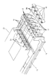
図1は、本発明の一実施形態にかかる筺体封止構造を適用した遊技機の制御基板ボックスを斜視図により示しており、図2は要部を拡大して示しており、図3は一部を破断して断面構造を見やすくして示している。
図において、筺体本体10は略矩形状とした全体形状のうち、相対面する辺にレール状のガイド部11,11を有しており、同様に略矩形形状とした蓋体20における相対面する辺に形成した鍔状部24,24を同ガイド部11,11に沿わせるようにしてスライドして装着できるようになっている。この例では、蓋体20の側が深みのある形状となっており、遊技機に使用する制御基板30をその部品載置面31の側から内面に対面させつつ、同制御基板30を保持するようにしている。
Hereinafter, embodiments of the present invention will be described with reference to the drawings.
FIG. 1 is a perspective view showing a control board box of a gaming machine to which a housing sealing structure according to an embodiment of the present invention is applied. FIG. 2 is an enlarged view of a main part, and FIG. The section is broken to make the cross-sectional structure easier to see.
In the figure, the
筺体本体10における上記ガイド部11,11の挿入端とは反対側の辺には複数の操作子保持部12が破断可能な板状壁材13にて連結されて形成されている。操作子保持部12はスライドして装着されてくる蓋体20に対面するように立設して形成されており、同蓋体20と対面する反対面に凹部12aを開口して形成してある。ここで、操作子保持部12は透明の樹脂で形成されている。
凹部12aの奥壁には互いに平行なスリット(貫通穴)12a1,12a1を形成してあり、二つのスリット12a1,12a1で挟まれる部分12a2は、図4に示すように略台形となっている。また、凹部12aの内周面は奥方へ向かうほど開口径が狭まるようなテーパー形状となっている。そして、凹部12aと反対の面には上記スリット12a1,12a1の開口部の外側から蓋体20の側に向かって板状の壁部12b,12bが立設されている。
A plurality of operating
Slits (through holes) 12a1 and 12a1 parallel to each other are formed in the back wall of the
樹脂製操作子40は上記凹部12a内に挿入できる大きさの略皿状に透明の樹脂にて形成されており、周囲の壁面は凹部12aの内周壁面のテーパー形状に沿うように前方へ向かうほど徐々に幅狭となる傾斜面となっている。皿状とした内側には断面U字形に屈曲した金属製係合片50が保持されている。同金属製係合片50は帯状の板材を断面U字形に屈曲させるとともに両端を内側に鋭角に折り返して形成されている。また、U字形に折り返した部分を樹脂製操作子40の凹み部分に挿入した状態で、抜け止めの樹脂片41を挿入して接着固定してある。
The
当初、樹脂製操作子40は金属製係合片50を保持した状態で操作子保持部12の凹部12a内に挿入されている。このとき、折り返し端51,51は上記スリット12a1,12a1を通過するときに撓めて押し込められることになり、一旦、通過すると折り返し端51,51がスリット12a1,12a1の間の部分12a2に引っかかるので抜け出なくなる。この状態を図4にて二点鎖線で示しており、この状態では樹脂製操作子40は凹部12aの最奥まで押し込まれておらず、残りの押し操作代が確保されている。
Initially, the
一方、蓋体20の側には上記操作子保持部12に対面するように固定受け構造21が形成されている。固定受け構造21の側にも上記スリット12a1,12a1に対面するようにスリット21a1,21a1が形成されているが、このスリット21a1,21a1の開口は広くなっており、操作子保持部12の側から立設されている板状の壁部12b,12bも当該スリット21a1,21a1内に挿入できるようになっている。従って、壁部12b,12bがスリット21a1,21a1内に挿入された時点では実質的に上記スリット12a1,12a1と同等の開口幅となる。
On the other hand, a fixed receiving
固定受け構造21の側でもスリット21a1,21a1の間には断面台形形状の被係合部21bが形成されている。被係合部21bには操作子保持部12に対面する側で開口を大きくし、反対の側で開口を狭めるようにテーパー状の傾斜面21b1,21b1を形成してある。また、操作子保持部12に対面する側と反対の側の面には凹部21b2を形成してある。
上記傾斜面21b1,21b1は金属製係合片50における折り返し端51,51を挿入しやすくするために形成され、凹部21b2はスリット21a1,21a1を通過した折り返し端51,51の先端が入り込んで食い込んで抜けにくくするために形成されている。抜けにくくするためにはこのような凹部の他、図5に示すように鋭角に折り返した折り返し端51に入り込むような鋭角の角部21b3,21b3を形成するようにしても良い。
On the fixed receiving
The inclined surfaces 21b1 and 21b1 are formed to facilitate the insertion of the folded ends 51 and 51 of the
図6は上記蓋体20を上記筺体本体10に対してスライドして装着し、上記固定受け構造21と上記操作子保持部12とが対面した状態で上記樹脂製操作子40を上記凹部12aの奥方に向けて押し操作して封止した状態を示している。
当初、広い開口となっていたスリット21a1,21a1内には、先ず、壁部12b,12bが入り込んで固定受け構造21と操作子保持部12との位置合わせをしつつ、開口を実質的にスリット12a1,12a1と同等とする。そして、樹脂製操作子40を押し込めば金属製係合片50の先端が上記スリット21a1,21a1内に押し込まれていく。このとき、折り返し端51,51は同スリット21a1,21a1を通過するために撓められ、同スリット21a1,21a1を通過したときに再度開く。開いた状態では折り返し端51,51の先端は被係合部21bの裏面に形成した凹部21b2に対面しており、蓋体20を筺体本体10から外すようにスライドさせようとしたときには同折り返し端51,51の先端が同凹部21b2内に入り込み、食い込むような形態となるので抜け出ることはない。
In FIG. 6, the
In the slits 21a1 and 21a1 which were initially wide openings, first, the
また、壁部12b,12bがスリット21a1,21a1内に入り込み、金属製係合片50を挟むようになっていることにより、同金属製係合片50を囲む壁面を二重にし、外部から不正を加えることを防止する効果もある。
押し操作する前は図4にて二点鎖線で示すように、樹脂製操作子40の外周壁面と凹部12aの内周壁面との間には隙間があるが、押し操作後は図6に示すように樹脂製操作子40の外周壁面と凹部12aの内周壁面との間にはほぼ隙間がなくなる。隙間が無くなることにより、外部から樹脂製操作子40を引き抜くことはほぼできなくなり、不正を防止できる。また、最初は隙間があるので、軽く押し込んでいくことができる。
Further, since the
Before the pressing operation, there is a gap between the outer peripheral wall surface of the
ここで、抜け出にくくする変形例として図7と図8に示すような金属製係合片52を採用することも可能である。
同図に示す金属製係合片150は、帯状板材の先端から幅方向に三等分するように切り込みを入れ、両側の二片を内側に折り返すとともに間の一片を外側に折り返してあり、板材の両面の側に折り返した折り返し端151,151を有している。
図8に示すように、この金属製係合片150を樹脂製操作子140に保持させ、上記折り返し端151,151の側から同操作子保持部112を凹部112a内に挿入する。すると、当初、スリット112a1,112a1を通過した状態で樹脂製操作子140は操作子保持部112に仮支持される。さらに、固定受け構造121を対面させてさらに樹脂製操作子140を押し操作すると、折り返し端151,151は固定受け部121の側に形成したスリット121a1,121a1の開口に押し当てられ、撓められて幅狭となりつつスリット121a1,121a1を通過する。そして、通過すると折り返し端151,151は元の幅に復元するので、折り返し形状を無理矢理開いてしまう程の力を掛けない限り抜け出ない。また、両側に折り返してあるので、スリット121a1の隙間内で片側に寄せてもいずれかの折り返し片がスリット121a1開口縁部に突き当たる。これは、折り返し端151を成形する際の製造誤差に要求される精度が低くても抜け出ないようにすることができ、品質管理上も容易になる。
Here, it is also possible to employ a metal engagement piece 52 as shown in FIGS.
The
As shown in FIG. 8, the
ところで、上述した操作子保持部12と固定受け構造21の図1〜3に示すように五対設けられている。また、筺体本体10における一辺上に五つの操作子保持部12が立設されており、蓋体20をスライドさせて筺体本体10に装着すると、蓋体20の一辺に形成された固定受け構造21が待ち受けている操作子保持部12へ当接するようになっている。ここで、固定受け構造21における上記金属製係合片50の折り返し端51,51が係合する部位は、実質的に蓋体20の内側、すなわち、当該筺体の内部に存在することになる。従って、不正を行なうために係合部位を解除するためには、筺体を開かなければならないので、実質的に不正は不可能となる。
By the way, as shown in FIGS. 1-3 of the operation element holding |
一方、検査を含めて必要時には筺体を開く必要もあるため、操作子保持部12を筺体本体10から切り離すことができる。図1〜図3に示すように操作子保持部12のそれぞれは樹脂製操作子40を収容可能な概略箱状に形成されているが、各操作子保持部12は板状壁材13にて連結されている。図9は各操作子保持部12を連結する板状壁材13の接続状況を示している。本来であれば、操作子保持部12を筺体本体10から立設せしめるように同図に示す下方にのみ板状壁材13が配置されているだけでも十分である。しかしながら、本実施形態では、横並びに配置される操作子保持部12の間にも板状壁材13が形成されている。操作子保持部12自体は不正に開かれていないか視認できるように配置されるべきであり、そのためには横並びの操作子保持部12の全てが視認できるように配置される。だとすると、操作子保持部12の並び方向の間に形成された板状壁材13も常に視認できるはずであり、不正に板状壁材13を壊した場合には容易に視認できる。これが、操作子保持部12の裏側だけであると破損部位を視認できにくくなる。
On the other hand, since it is necessary to open the casing when necessary including inspection, the operation
一方、操作子保持部12は横並び方向に対称に形成されており、一見すると各操作子保持部12を支持する板状壁材13の数は同様であるが、実際の使用時には異なる。例えば、図9に示すように、初めて操作子保持部12を解除するときには破損部位を○で示すように三つの板状壁材13を破損しなければならない。しかしながら、二つ目の操作子保持部12を解除するときには△で示すように破損すべき板状壁材13は二ヶ所になる。この差異は、解除のしやすさに影響を与えるので、通常は解除すること自体が殆ど無いのであれば、最初に解除する際に破損すべき板状壁材13の数が多いほど不正をしにくくなる。
On the other hand, the operation
また、検査の工程を経る前に一度組み付ける必要があるというようなときには必ず一度は解除しなければならないことが明らかである。このため、最初の操作子保持部12については下方の板状壁材13だけで支持する構成としておき、横並びの間の板状壁材13も形成しておかないというようにしても良い。このようにすれば、検査工程の際に一つの板状壁材13だけを破損すればよいし、また、破損箇所が表からは見えないので製品として出荷する際の見栄えも良い。
In addition, it is clear that it must be released once when it is necessary to assemble it once before going through the inspection process. For this reason, the first
なお、板状壁材13の破損させやすさは、板状壁材13の数だけでなく、厚みによっても調整可能である。
ところで、板状壁材13の中でも操作子保持部12の陰に隠れている部分については、正面側から破壊を視認できにくい。このため、図10に示すように、同板状壁材13aを障害物である操作子保持部12の陰から外方へと延設するようにしてもよい。このようにすると、延設した板状壁材13aを削ったり破壊したりする不正を行った場合でも正面の側から容易に視認できるようになる。
The ease with which the plate-
By the way, about the part hidden behind the operation element holding |
また、上述した実施形態では、操作子保持部12と樹脂製操作子40はともに透明の樹脂で形成しているが、樹脂製操作子40に着色することにより、不正の防止を図ることができる。例えば、制御ボックスのバージョンやロット、あるいは仕向店舗ごとに着色の組み合わせを変えることが可能となる。不正の一手段として、古い機種の制御ボックスや古いバージョンの制御ボックスに不正を行っておき、制御ボックスごと取り替えてしまう手法がある。しかしながら、バージョンやロットあるいは仕向店舗毎に着色の組み合わせを変えておけば、他の機種などの制御ボックスとは着色の組み合わせが異なるので、交換してもすぐに視認できてしまうからである。
In the above-described embodiment, the operation
着色の手法は、樹脂製操作子40に着色しても良いし、この樹脂製操作子40は透明としつつ、内側に装着される樹脂片41に着色してもよい。後者の場合も、樹脂片41の周りは透明の部材であるので、容易に着色を視認できる。
本実施形態では、スライドして脱着される蓋体20の側に制御基板30を保持させる構成としてある。図11は保持状態を断面図により示している。通常、筺体本体に制御基板を保持してあると、蓋体というのは制御基板に対して密着させることができず、どこかに隙間が生じがちである。例えば、ケーブルの引きだし部位に隙間が生じ、この隙間から異物を差し込んで不正を行おうとする可能性がある。
As a coloring method, the
In the present embodiment, the
しかしながら、本実施形態では、深みのある形状となっている蓋体20に対して制御基板30をその部品載置面31の側から内面に対面させて収容している。また、蓋体20の内周面から制御基板30上の重要部品であるICソケット32とIC33を取り囲むように遮蔽壁材22を立設させ、同遮蔽壁材22の先端がほぼ制御基板30の表面に当接している。このため、異物にてIC33に到達しうることは不可能となっている。
However, in this embodiment, the
また、ケーブル34についても、ケーブル34自体は外部に導出させなければならないので制御基板30の表面を外部に露出させなければならない。しかし、開口部位から当該ケーブル34の周囲で制御基板30に当接しうる程度の長さの遮蔽壁材23を形成しておくことにより、隙間が生じない。これにより、異物などを挿入させること自体も不可能になる。
図12は、本発明の変形例を示している。先の実施形態では、操作子保持部12と固定受け構造21とが蓋体20と筺体本体10とのスライドで互いに対面しているが、この変形例では、スライド面を挟んで操作子保持部12と固定受け構造21とが対面している。従って、蓋体20を筺体本体10に対して徐々にスライドさせていくことにより、両者は徐々に重なり合い始め、最終的に対面する。この対面状態で、樹脂製操作子40を操作子保持部12の奥まで押し込むことにより、保持されている金属製係合片50がスライド面を横切り、相手側の固定受け構造21へと入っていって係合する。
Further, since the
FIG. 12 shows a modification of the present invention. In the previous embodiment, the operating
また、このようにスライド面を挟んで対面する構造の変形例として、図13と図14に示すような構成とすることもできる。
同図に示すものでは、操作子保持部112の側に保持されている樹脂製操作子240の全長を長く設定してあるとともに、固定受け構造221の側には同樹脂製操作子240の先端を挿入可能な凹部225を形成してある。
このように形成してあることにより、樹脂製操作子240に対して押し操作すると同樹脂製操作子240が操作子保持部212の奥方に押し込まれ、この結果、同樹脂製操作子240がスライド面を横切って凹部225内に入り込むとともに、金属製係合片250も係合する。同樹脂製操作子240がスライド面を横切っていることにより、蓋体と筺体本体とをスライドさせようとしても樹脂製操作子240がそのような移動を規制し、スライドさせることができない。この結果、封止の機能をより強固にさせることができる。
Further, as a modification of the structure facing each other with the slide surface interposed therebetween, a configuration as shown in FIGS. 13 and 14 can be adopted.
In the figure, the total length of the
As a result, when the
なお、図15はパチンコ機を背面図により示しており、本筺体封止構造を適用した制御ボックスが背面側から視認できるように装着されている。
パチンコ遊技機60の背面側には矩形箱形の制御ボックス70が装着されている。ここで、同制御ボックス70は長辺の一辺に形成した蝶番機構にて蓋体と筺体とが開閉可能になっており、両方の短辺には本筺体封止構造が採用されている。すなわち、蓋体の固定受け構造21と筺体の操作子保持部12はそれぞれ蓋体と筺体の短辺にそれぞれ4対ずつ形成されており、封止可能となっている。むろん、必要に応じて開口させることもできる。図に示すように、パチンコ機60の背面側から直に視認できる位置に配設されているため、メンテナンスのためにパチンコ機60を開いたときには容易に視認できる。従って、制御ボックス70内に手を加えるなどのために固定受け構造21や操作子保持部12を破損させれば、次のメンテナンス時にはすぐに見つかってしまう。
FIG. 15 shows the pachinko machine in a rear view, and a control box to which the main body sealing structure is applied is mounted so that it can be seen from the back side.
A rectangular box-shaped
また、図16はスロットマシン(パチスロ)80の背面を示している。同スロットマシン80の背面側にも矩形箱形の制御ボックス90が装着されている。ここで、同制御ボックス90は図示しない蝶番機構にて蓋体と筺体とが開閉可能になっており、両方の短辺には本筺体封止構造が採用されている。すなわち、蓋体の固定受け構造21と筺体の操作子保持部12はそれぞれ蓋体と筺体の短辺にそれぞれ4対ずつ形成されており、封止可能であるし、必要に応じて開口させることもできる。
FIG. 16 shows the back of the slot machine (pachi slot) 80. A rectangular box-shaped
同図に示すように、スロットマシン80の背面側にも制御ボックス90が装着され、メンテナンスのためにスロットマシン80を開いたときには容易に筺体封止構造を視認できる。従って、制御ボックス90内に手を加えるなどのために固定受け構造21や操作子保持部12を破損させれば、次のメンテナンス時にはすぐに見つかってしまう。
図示していないが、パチロットにも同様に適用可能である。パチロットは、メダルの代わりにパチンコ遊技球を利用するものであり、例えば、パチンコ球の5個がメダル1個に相当して遊技を楽しむことができる。
As shown in the figure, a
Although not shown, the present invention can be similarly applied to a patty lot. The pacilot uses a pachinko game ball instead of a medal. For example, five pachinko balls can be equivalent to one medal and enjoy a game.
このように、凹部12aを有する操作子保持部12を筺体本体10の側に設けつつ、同凹部12aには金属製係合片50を保持する樹脂製操作子40を仮支持しておき、上記筺体本体10に装着される蓋体20の側には当該蓋体20がスライドして装着される際に上記操作子保持部12に対面する部位に固定受け構造21を形成してあり、スライドして筺体本体10と蓋体20とを装着させたときに上記樹脂製操作子40を押し操作すると上記金属製係合片50の折り返し端51が上記固定受け構造21のスリット21a1内に入り込んで係合し、封止が完了する。
Thus, while providing the operation
10…筺体本体(制御ボックスの一部)
12…操作子保持部(保持部)
12b…壁部
20…蓋体(制御ボックスの一部)
21…固定受け構造
40…樹脂製操作子(操作部材)
10 ... Body body (part of control box)
12 ... Operator holding part (holding part)
12b ...
21 ... Fixed receiving
Claims (1)
前記筺体本体と前記蓋体とは、互いをスライドさせて前記開口部を閉鎖させる場合に対面するスライド面を有する構成であって、
前記筐体本体と前記蓋体のうち一方の部材には封止用の固定受け構造が形成され、他方の部材には前記開口部を閉鎖した際、前記固定受け構造と相対面する位置に前記操作部材を保持する保持部が形成され、前記固定受け構造の内側には開口を形成する壁部が設けられ、
前記操作部材は、前記固定受け構造に対して前記スライド面を横切って係合固定可能な位置に保持されており、前記固定受け構造および前記壁部により形成される二重の壁面に挟まれた状態で前記固定受け構造に係合固定されることを特徴とする遊技機。 The opening of the box body to be controlled box closed by a lid, a the lid and front Symbol gaming machine that employs the housing sealing structure for sealed with the operating member and the box body,
The casing main body and the lid body have a slide surface that faces each other when the opening is closed by sliding each other,
Before the one member of the Kikatamitai main body and the lid are formed fixed receiving structure for sealing is, upon closing the opening in the other member, to the fixed receiving Structure and Phase opposing position A holding portion for holding the operation member is formed, and a wall portion for forming an opening is provided inside the fixed receiving structure.
The operating member is pre SL are held in engagement fixable positions across the sliding surface with respect to the fixed receiving structure is sandwiched double wall formed by the fixed receiving structure and the wall portion A gaming machine, wherein the gaming machine is engaged and fixed to the fixed receiving structure .
Priority Applications (1)
| Application Number | Priority Date | Filing Date | Title |
|---|---|---|---|
| JP2008257906A JP4793420B2 (en) | 2008-10-03 | 2008-10-03 | Game machine |
Applications Claiming Priority (1)
| Application Number | Priority Date | Filing Date | Title |
|---|---|---|---|
| JP2008257906A JP4793420B2 (en) | 2008-10-03 | 2008-10-03 | Game machine |
Related Parent Applications (1)
| Application Number | Title | Priority Date | Filing Date |
|---|---|---|---|
| JP2002048255A Division JP2003245450A (en) | 2002-02-25 | 2002-02-25 | Game machine |
Publications (3)
| Publication Number | Publication Date |
|---|---|
| JP2009000565A JP2009000565A (en) | 2009-01-08 |
| JP2009000565A5 JP2009000565A5 (en) | 2009-06-25 |
| JP4793420B2 true JP4793420B2 (en) | 2011-10-12 |
Family
ID=40317546
Family Applications (1)
| Application Number | Title | Priority Date | Filing Date |
|---|---|---|---|
| JP2008257906A Expired - Fee Related JP4793420B2 (en) | 2008-10-03 | 2008-10-03 | Game machine |
Country Status (1)
| Country | Link |
|---|---|
| JP (1) | JP4793420B2 (en) |
Families Citing this family (1)
| Publication number | Priority date | Publication date | Assignee | Title |
|---|---|---|---|---|
| JP2012055529A (en) * | 2010-09-10 | 2012-03-22 | Daito Giken:Kk | Board case for game machine |
-
2008
- 2008-10-03 JP JP2008257906A patent/JP4793420B2/en not_active Expired - Fee Related
Also Published As
| Publication number | Publication date |
|---|---|
| JP2009000565A (en) | 2009-01-08 |
Similar Documents
| Publication | Publication Date | Title |
|---|---|---|
| JP5644021B2 (en) | Board storage case for gaming machine and gaming machine having the same | |
| JP5166595B2 (en) | Game machine | |
| JP2003245450A (en) | Game machine | |
| JP5300646B2 (en) | Game machine | |
| JP4793420B2 (en) | Game machine | |
| JP2009000565A5 (en) | ||
| JP2004073896A (en) | Game machine | |
| JP5788479B2 (en) | Game machine | |
| JP5703613B2 (en) | Game machine | |
| JP2009160473A (en) | Board box for game machine | |
| JP4879141B2 (en) | Game machine and protection device for control board for game machine | |
| JP5467943B2 (en) | Board case for gaming machine and gaming machine having the same | |
| JP5703614B2 (en) | Game machine | |
| JP6461883B2 (en) | GAME MACHINE MEMBER AND GAME MACHINE | |
| JP6461884B2 (en) | GAME MACHINE MEMBER AND GAME MACHINE | |
| JP5804129B2 (en) | Game machine | |
| JP5527069B2 (en) | Game machine | |
| JP5442837B2 (en) | Game machine | |
| JP5527068B2 (en) | Game machine | |
| JP2004105755A (en) | Game machine | |
| JP4359351B2 (en) | Board storage case for gaming machine | |
| JP4735669B2 (en) | Game machine | |
| JP5227916B2 (en) | Game machine | |
| JP4356770B2 (en) | Game machine | |
| JP2004089734A (en) | Game machine |
Legal Events
| Date | Code | Title | Description |
|---|---|---|---|
| A621 | Written request for application examination |
Free format text: JAPANESE INTERMEDIATE CODE: A621 Effective date: 20081031 |
|
| A521 | Request for written amendment filed |
Free format text: JAPANESE INTERMEDIATE CODE: A523 Effective date: 20090513 |
|
| RD02 | Notification of acceptance of power of attorney |
Free format text: JAPANESE INTERMEDIATE CODE: A7422 Effective date: 20090513 |
|
| TRDD | Decision of grant or rejection written | ||
| A01 | Written decision to grant a patent or to grant a registration (utility model) |
Free format text: JAPANESE INTERMEDIATE CODE: A01 Effective date: 20110628 |
|
| A01 | Written decision to grant a patent or to grant a registration (utility model) |
Free format text: JAPANESE INTERMEDIATE CODE: A01 |
|
| A61 | First payment of annual fees (during grant procedure) |
Free format text: JAPANESE INTERMEDIATE CODE: A61 Effective date: 20110711 |
|
| R150 | Certificate of patent or registration of utility model |
Ref document number: 4793420 Country of ref document: JP Free format text: JAPANESE INTERMEDIATE CODE: R150 Free format text: JAPANESE INTERMEDIATE CODE: R150 |
|
| FPAY | Renewal fee payment (event date is renewal date of database) |
Free format text: PAYMENT UNTIL: 20140805 Year of fee payment: 3 |
|
| R250 | Receipt of annual fees |
Free format text: JAPANESE INTERMEDIATE CODE: R250 |
|
| R250 | Receipt of annual fees |
Free format text: JAPANESE INTERMEDIATE CODE: R250 |
|
| R250 | Receipt of annual fees |
Free format text: JAPANESE INTERMEDIATE CODE: R250 |
|
| R250 | Receipt of annual fees |
Free format text: JAPANESE INTERMEDIATE CODE: R250 |
|
| R250 | Receipt of annual fees |
Free format text: JAPANESE INTERMEDIATE CODE: R250 |
|
| R250 | Receipt of annual fees |
Free format text: JAPANESE INTERMEDIATE CODE: R250 |
|
| R250 | Receipt of annual fees |
Free format text: JAPANESE INTERMEDIATE CODE: R250 |
|
| LAPS | Cancellation because of no payment of annual fees |