JP4792805B2 - Display device - Google Patents
Display device Download PDFInfo
- Publication number
- JP4792805B2 JP4792805B2 JP2005133571A JP2005133571A JP4792805B2 JP 4792805 B2 JP4792805 B2 JP 4792805B2 JP 2005133571 A JP2005133571 A JP 2005133571A JP 2005133571 A JP2005133571 A JP 2005133571A JP 4792805 B2 JP4792805 B2 JP 4792805B2
- Authority
- JP
- Japan
- Prior art keywords
- image light
- screen
- image
- light
- liquid crystal
- Prior art date
- Legal status (The legal status is an assumption and is not a legal conclusion. Google has not performed a legal analysis and makes no representation as to the accuracy of the status listed.)
- Expired - Fee Related
Links
Images
Landscapes
- Overhead Projectors And Projection Screens (AREA)
- Liquid Crystal (AREA)
Description
この発明は、立体的な画像を表示する表示装置に関する。 The present invention relates to a display device that displays a stereoscopic image.
表示装置として、液晶層を挟んで対向する一対の基板の対向する内面のうち、一方の基板の内面に、予め定めた形状の複数の主セグメント電極と、これらの主セグメント電極の半周の縁部に隣接させてその縁部の輪郭形状に形成された複数の副セグメント電極とを設け、他方の基板の内面に、前記複数の主セグメント電極及び副セグメント電極に対向するコモン電極を設けた液晶表示素子を備え、前記液晶表示素子に、前記主セグメント電極の形状に対応する主表示パターンと、前記副セグメント電極の形状に対応する副表示パターン(主表示パターンの半周に沿う影のような輪郭パターン)とからなる、前記副表示パターンにより厚みを表現した図形、つまり、厚みのある形状物を斜め方向から見たような図形を表示させるようにしたものがある(特許文献1参照)。
しかし、上記従来の表示装置の表示は、奥行き感の無い平面的な表示である。 However, the display of the conventional display device is a flat display without a sense of depth.
この発明は、奥行き感のある立体的な画像を表示することができる表示装置を提供することを目的としたものである。 An object of the present invention is to provide a display device capable of displaying a stereoscopic image with a sense of depth.
この発明の表示装置は、互いに逆向きの前面と後面とを有し、前記前面を観察側に対向させて配置され、前記前面から入射した光を前記観察側に反射し、前記後面から入射した光を透過させて前記観察側に出射するスクリーンと、第1と第2の画像光を出射し、前記第1の画像光を、前記スクリーンの前側から前記スクリーンの前面に向けて投影し、前記第2の画像光を、前記スクリーンの後側から前記スクリーンの後面に向けて前記スクリーンの前記第1の画像光の投影領域に入射させるように投影する画像光投影手段とを備え、
画像光投影手段は、
光の透過を制御する複数の画素をマトリックス状に配列した画面領域を有する1つの液晶表示素子と、前記液晶表示素子の一方の面と他方の面とにそれぞれ対向させて配置され、前記液晶表示素子に向けて照明光を出射し、前記液晶表示素子からの出射光を透過させる第1と第2の面光源とからなり、前記液晶表示素子の一方の面と他方の面からそれぞれ画像光を出射し、前記液晶表示素子の前記第2の面光源に対向する面から出射した第1の画像光を前記第2の面光源を透過させて出射し、前記液晶表示素子の前記第1の面光源に対向する面から出射した第2の画像光を前記第1の面光源を透過させて出射する画像光出射部と、
前記画像光出射部からの前記第1と第2の画像光をそれぞれスクリーンの前面と後面に向けて反射する第1と第2の反射板とを備えており、
前記画像光出射部は、前記スクリーンの側方に、前記第1の画像光の出射方向を前記スクリーンの前側方向に向け、前記第2の画像光の出射方向を前記スクリーンの後側方向に向けて配置され、
前記第1の反射板は、前記画像光出射部からの前記第1の画像光の出射方向に、前記第1の画像光を前記スクリーンの前面に向けて反射するように配置され、前記第2の反射板は、前記画像光出射部からの前記第2の画像光の出射方向に、前記第2の画像光を前記スクリーンの後面に向けて反射するように配置されていることを特徴とする。
The display device of the present invention has a front surface and a rear surface that are opposite to each other, and is disposed with the front surface facing the observation side, reflects light incident from the front surface to the observation side, and enters from the rear surface A screen that transmits light and exits to the observation side; emits first and second image light; and projects the first image light from the front side of the screen toward the front surface of the screen; Image light projecting means for projecting the second image light from the rear side of the screen toward the rear surface of the screen so as to enter the projection area of the first image light of the screen ;
The image light projection means
One liquid crystal display element having a screen region in which a plurality of pixels for controlling the transmission of light are arranged in a matrix, and one liquid crystal display element and one surface of the liquid crystal display element are arranged to face each other, and the liquid crystal display It comprises first and second surface light sources that emit illumination light toward the element and transmit light emitted from the liquid crystal display element. Image light is emitted from one surface and the other surface of the liquid crystal display element, respectively. The first image light emitted from the surface facing the second surface light source of the liquid crystal display element is emitted through the second surface light source, and the first surface of the liquid crystal display element is emitted. An image light emitting unit for emitting the second image light emitted from the surface facing the light source through the first surface light source;
Comprising first and second reflecting plates for reflecting the first and second image lights from the image light emitting section toward the front and rear surfaces of the screen, respectively.
The image light emitting unit directs the emission direction of the first image light toward the front side of the screen and the emission direction of the second image light toward the rear side of the screen toward the side of the screen. Arranged,
The first reflection plate is arranged to reflect the first image light toward the front surface of the screen in the emission direction of the first image light from the image light emission unit, and the second reflection plate. The reflection plate is arranged to reflect the second image light toward the rear surface of the screen in the emission direction of the second image light from the image light emission unit. .
好ましくは、この発明の表示装置において、前記画像光投影手段は、前記第1の画像光と第2の画像光の出射強度比を調整する手段を備えている。
好ましくは、スクリーンは、その後面に、画像光出射部から第2の反射板を介して投影された第2の画像光を前記スクリーンの法線付近の方向に屈折させて前記スクリーンに入射させる入射角制御手段を有し、前面に、前記画像光出射部から第1の反射板を介して投影された第1の画像光の反射方向を前記スクリーンを透過した前記第2の画像光の出射方向と実質的に一致させる反射方向制御手段を有している。
好ましくは、スクリーンは、半透過反射板からなっている。
好ましくは、スクリーンは、互いに直交する反射軸と透過軸をもち、入射光の互いに直交する2つの直線偏光成分のうち、前記反射軸に平行な直線偏光成分を反射し、前記透過軸に平行な直線偏光成分を透過させる反射偏光板からなっており、画像光投影手段は、前記反射偏光板の反射軸と実質的に平行な直線偏光からなる第1の画像光を前記スクリーンの前面に向けて投影し、前記反射偏光板の透過軸と実質的に平行な直線偏光からなる第2の画像光を前記スクリーンの後面に向けて投影する。
Preferably, in the display device of the present invention, the image light projection means, that comprise means for adjusting the emission intensity ratio of the first image light and the second image light.
Preferably, the screen is incident on the rear surface thereof by causing the second image light projected from the image light emitting unit via the second reflector to be refracted in the direction near the normal of the screen and incident on the screen. A direction of the first image light that has angle control means and is transmitted through the screen in the reflection direction of the first image light projected from the image light emitting unit via the first reflector on the front surface. And a reflection direction control means that substantially coincides with.
Preferably, the screen is made of a transflective plate.
Preferably, the screen has a reflection axis and a transmission axis orthogonal to each other, and reflects a linearly polarized light component parallel to the reflection axis among two linearly polarized light components orthogonal to the incident light, and is parallel to the transmission axis. The image light projecting means is configured to direct the first image light composed of linearly polarized light substantially parallel to the reflection axis of the reflective polarizing plate toward the front surface of the screen. And projecting the second image light composed of linearly polarized light substantially parallel to the transmission axis of the reflective polarizing plate toward the rear surface of the screen.
この発明の表示装置は、前面を観察側に対向させて配置され、前記前面から入射した光を前記観察側に反射し、反対側の後面から入射した光を透過させて前記観察側に出射するスクリーンと、第1と第2の画像光を出射し、前記第1の画像光を、前記スクリーンの前側から前記スクリーンの前面に向けて投影し、前記第2の画像光を、前記スクリーンの後側から前記スクリーンの後面に向けて前記スクリーンの前記第1の画像光の投影領域に入射させるように投影する画像光投影手段とを備え、画像光投影手段は、光の透過を制御する複数の画素をマトリックス状に配列した画面領域を有する1つの液晶表示素子と、前記液晶表示素子の一方の面と他方の面とにそれぞれ対向させて配置され、前記液晶表示素子に向けて照明光を出射し、前記液晶表示素子からの出射光を透過させる第1と第2の面光源とからなり、前記液晶表示素子の一方の面と他方の面からそれぞれ画像光を出射し、前記液晶表示素子の前記第2の面光源に対向する面から出射した第1の画像光を前記第2の面光源を透過させて出射し、前記液晶表示素子の前記第1の面光源に対向する面から出射した第2の画像光を前記第1の面光源を透過させて出射する画像光出射部と、前記画像光出射部からの前記第1と第2の画像光をそれぞれスクリーンの前面と後面に向けて反射する第1と第2の反射板とを備えており、前記画像光出射部は、前記スクリーンの側方に、前記第1の画像光の出射方向を前記スクリーンの前側方向に向け、前記第2の画像光の出射方向を前記スクリーンの後側方向に向けて配置され、前記第1の反射板は、前記画像光出射部からの前記第1の画像光の出射方向に、前記第1の画像光を前記スクリーンの前面に向けて反射するように配置され、前記第2の反射板は、前記画像光出射部からの前記第2の画像光の出射方向に、前記第2の画像光を前記スクリーンの後面に向けて反射するように配置されているものであるため、前記スクリーンにその前側から投影され、前記スクリーンにより観察側に反射された前記第1の画像光からなる第1の画像と、前記スクリーンにその後側から投影され、前記スクリーンを透過して前記観察側に出射した前記第2の画像光からなる第2の画像とが重なって見える、奥行き感のある立体的な画像を表示することができるとともに、前記スクリーンの後面に、前記画像光出射部から前記第2の反射板を介して投影された前記第2の画像光を前記スクリーンの法線付近の方向に屈折させて前記スクリーンに入射させる入射角制御手段を設け、前記スクリーンの前面に、前記画像光出射部から前記第2の反射板を介して投影された前記第1の画像光の反射方向を前記スクリーンを透過した前記第2の画像光の出射方向と実質的に一致させる反射方向制御手段を設けるのが好ましく、このようにすることにより、奥行き感のある立体的な画像を前記スクリーンの前面の正面方向から観察させることができる。 The display device of the present invention is disposed with the front surface facing the observation side, reflects light incident from the front surface to the observation side, transmits light incident from the rear surface on the opposite side, and emits the light to the observation side. A screen, and first and second image lights, the first image light is projected from the front side of the screen toward the front surface of the screen, and the second image light is projected after the screen. Image light projecting means for projecting from the side toward the projection surface of the first image light of the screen toward the rear surface of the screen , and the image light projecting means controls a plurality of light transmissions. One liquid crystal display element having a screen region in which pixels are arranged in a matrix, and one surface and the other surface of the liquid crystal display element are arranged to face each other, and emits illumination light toward the liquid crystal display element And said A first surface light source and a second surface light source that transmit light emitted from the crystal display element; image light is emitted from one surface and the other surface of the liquid crystal display element; The first image light emitted from the surface facing the surface light source is transmitted through the second surface light source and emitted from the surface facing the first surface light source of the liquid crystal display element. An image light emitting unit that emits image light through the first surface light source, and a first light that reflects the first and second image light from the image light emitting unit toward the front and rear surfaces of the screen, respectively. 1 and a second reflecting plate, and the image light emitting section is directed to the side of the screen with the first image light emitting direction directed to the front side of the screen. The light is emitted in the direction of the rear side of the screen, The first reflection plate is arranged to reflect the first image light toward the front surface of the screen in the emission direction of the first image light from the image light emission unit, and the second reflection plate The plate is arranged so as to reflect the second image light toward the rear surface of the screen in the emission direction of the second image light from the image light emission unit. A first image composed of the first image light projected from the front side and reflected to the observation side by the screen, and projected from the rear side to the screen and transmitted through the screen and emitted to the observation side. A stereoscopic image with a sense of depth that appears to overlap with the second image made of the second image light can be displayed , and the second light from the image light emitting unit can be displayed on the rear surface of the screen. Reflector An incident angle control means for refracting the second image light projected through the screen in a direction near the normal line of the screen and making it incident on the screen is provided, and the image light emitting unit is provided on the front surface of the screen from the image light emitting unit. It is preferable to provide a reflection direction control unit that substantially matches the reflection direction of the first image light projected through the second reflector with the emission direction of the second image light transmitted through the screen. In this way, a stereoscopic image with a sense of depth can be observed from the front direction of the front surface of the screen .
この発明の表示装置において、前記画像光投影手段は、前記第1の画像光と第2の画像光の出射強度比を調整する手段を備えているのが望ましく、このようにすることにより、前記立体的な画像の奥行き感を任意に変化させることができる。 In the display device according to the aspect of the invention, it is preferable that the image light projecting unit includes a unit that adjusts an emission intensity ratio of the first image light and the second image light. It is possible to arbitrarily change the depth of the three-dimensional image.
その場合は、前記スクリーンの後面に、前記画像光出射部から前記第2の反射板を介して投影された前記第2の画像光を前記スクリーンの法線付近の方向に屈折させて前記スクリーンに入射させる入射角制御手段を設け、前記スクリーンの前面に、前記画像光出射部から前記第2の反射板を介して投影された前記第1の画像光の反射方向を前記スクリーンを透過した前記第2の画像光の出射方向と実質的に一致させる反射方向制御手段を設けるのが好ましく、このようにすることにより、奥行き感のある立体的な画像を前記スクリーンの前面の正面方向から観察させることができる。 In that case, the second image light projected from the image light emitting unit via the second reflector on the rear surface of the screen is refracted in the direction near the normal line of the screen to the screen. Incident angle control means is provided, and the reflection direction of the first image light projected from the image light emitting unit through the second reflector is transmitted to the front surface of the screen through the screen. It is preferable to provide a reflection direction control means that substantially matches the emission direction of the image light of No. 2, so that a stereoscopic image with a sense of depth can be observed from the front direction of the front surface of the screen. Can do.
また、この発明の表示装置において、前記スクリーンは、半透過反射板が好ましく、このようにすることにより、前記スクリーンにその前面から入射した前記第1の画像光を観察側に反射し、前記スクリーンにその後面から入射した前記第2の画像光を光を透過させて前記観察側に出射することができる。 In the display device of the present invention, the screen is preferably a transflective plate. By doing so, the first image light incident on the screen from its front surface is reflected to the observation side, and the screen Then, the second image light incident from the rear surface can be transmitted and emitted to the observation side.
前記スクリーンは、互いに直交する反射軸と透過軸をもち、入射光の互いに直交する2つの直線偏光成分のうち、前記反射軸に平行な直線偏光成分を反射し、前記透過軸に平行な直線偏光成分を透過させる反射偏光板でもよく、その場合は、前記画像光投影手段を、前記反射偏光板の反射軸と実質的に平行な直線偏光からなる第1の画像光を前記スクリーンの前面に向けて投影し、前記反射偏光板の透過軸と実質的に平行な直線偏光からなる第2の画像光を前記スクリーンの後面に向けて投影するように構成することにより、前記スクリーンにその前面から入射した前記第1の画像光を観察側に反射し、前記スクリーンにその後面から入射した前記第2の画像光を透過させて前記観察側に出射することができる。 The screen has a reflection axis and a transmission axis that are orthogonal to each other, and reflects a linearly polarized light component that is parallel to the reflection axis of two linearly polarized light components that are orthogonal to each other of incident light, and is linearly polarized light that is parallel to the transmission axis. A reflective polarizing plate that transmits the component may be used. In this case, the image light projecting unit directs the first image light composed of linearly polarized light substantially parallel to the reflection axis of the reflective polarizing plate toward the front surface of the screen. And projecting the second image light composed of linearly polarized light substantially parallel to the transmission axis of the reflective polarizing plate toward the rear surface of the screen, thereby entering the screen from its front surface. The first image light reflected can be reflected to the observation side, and the second image light incident from the rear surface to the screen can be transmitted and emitted to the observation side.
(第1の実施形態)
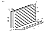
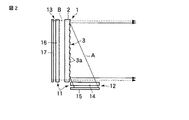
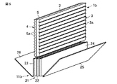
図1及び図2はこの発明の第1の実施例を示しており、図1は表示装置の斜視図、図2は前記表示装置の側面図である。
(First embodiment)
1 and 2 show a first embodiment of the present invention. FIG. 1 is a perspective view of a display device, and FIG. 2 is a side view of the display device.
この表示装置は、互いに逆向きの前面と後面とを有し、前記前面を観察側(図2において右側)に対向させて配置され、前記前面から入射した光を前記観察側に反射し、前記後面から入射した光を透過させて前記観察側に出射するスクリーン1と、前記スクリーン1に前記観察側から見て実質的に同一パターンの2つの平面的な画像を投影するための第1と第2の画像光を出射し、前記第1の画像光を、前記スクリーン1の前側の領域(スクリーン1の前面に対向する領域)の側方から前記スクリーン1の前面に向けて投影し、前記第2の画像光を、前記スクリーン1の後側から前記スクリーン1の後面に向けて投影して前記スクリーン1の前記第1の画像光の投影領域に入射させる画像光投影手段11とを備えている。
The display device has a front surface and a rear surface that are opposite to each other, and is disposed with the front surface facing the observation side (right side in FIG. 2), and reflects light incident from the front surface to the observation side, A
この実施例の表示装置において、前記画像光投影手段11は、第1の画像光出射部12と第2の画像光出射部13とを備えている。
In the display device of this embodiment, the image
前記第1の画像光出射部12は、光の透過を制御する複数の画素(図示せず)がマトリックス状に配列された画面領域14aを有する第1の液晶表示素子14と、前記第1の液晶表示素子14の一方の面に対向させて配置され、前記第1の液晶表示素子14に向けて照明光を出射する第1の面光源15とからなっており、前記第1の液晶表示素子14の複数の画素に画像データに応じた駆動電圧が印加されて第1の画像を表示し、その第1の画像光Aを前記第1の液晶表示素子14の他方の面から出射する。
The first image
また、前記第2の画像光出射部13は、光の透過を制御する複数の画素(図示せず)がマトリックス状に配列した画面領域16aを有する第2の液晶表示素子16と、前記第2の液晶表示素子16の一方の面に対向させて配置され、前記第2の液晶表示素子16に向けて照明光を出射する第2の面光源17とからなっており、前記第2の液晶表示素子16の複数の画素に画像データに応じた駆動電圧が印加されて第2の画像を表示し、その第2の画像光Bを前記第2の液晶表示素子16の他方の面から出射する。
The second image
なお、図1及び図2では前記第1と第2の液晶表示素子14,16を簡略化して示しているが、これらの液晶表示素子14,16は、例えばアクティブマトリックス型のものであり、液晶層を挟んで対向する一対の透明基板の互いに対向する内面のうち、一方の基板の内面に、行方向及び列方向にマトリックス状に配列した複数の透明な画素電極と、これらの画素電極にそれぞれ接続された複数のTFT(薄膜トランジスタ)と、各行のTFTにゲート信号を供給する複数のゲート配線と、各列のTFTにデータ信号を供給する複数のデータ配線が設けられ、他方の基板の内面に、前記複数の画素電極と対向する一枚膜状の透明な対向電極が設けられ、一対の透明基板の外面にそれぞれ偏光板が設けられた構造となっている。
1 and 2 show the first and second liquid
また、図1及び図2では前記第1と第2の面光源15,17を簡略化して示しているが、これらの面光源15,17は、例えば、前記液晶表示素子14,16の画面領域14a,16aの全域に対向する面積を有する板状の透明部材の一端面に光を入射させる入射端面が形成され、2つの板面の一方に前記入射端面から入射した光の出射端面が形成され、他方の板面に前記入射端面から入射した光を前記出射面に向けて反射する反射面が形成された導光板と、前記導光板の入射端面に対向させて配置され、前記入射端面に向けて光を出射するLED(発光ダイオード)等の複数の固体発光素子からなっている。
1 and 2 show the first and second
前記第1の画像光出射部12は、前記スクリーン1の前側領域の側方に、前記第1の画像光Aの出射方向を前記スクリーン1の前面に向けて配置され、前記第2の画像光出射部13は、前記スクリーン1の後側に、前記第2の画像光Bの出射方向を前記スクリーン1の後面に向けて配置されている。
The first image
この実施例では、前記スクリーン1を垂直に立てて配置し、前記第1の画像光出射部12を、前記スクリーン1の前側領域の下側に、前記第1の画像光の出射面(第1の液晶表示素子14の面光源15側とは反対側の面)を上方に向けて水平に、つまり前記スクリーン1に対して直角に配置し、前記第2の画像光出射部13を、前記スクリーン1の真後に、第2の画像光の出射面(第2の液晶表示素子16の面光源17側とは反対側の面)を前記スクリーン1の後面に実質的に平行に対向させて配置している。
In this embodiment, the
そして、前記第1の画像光出射部12を構成する第1の液晶表示素子14は、前記スクリーン1の左右方向に沿った方向の画面長さが前記スクリーン1の外周部を除く領域(以下、利用領域という)の左右方向幅と実質的に同じに設定され、前記スクリーン1の上下方向に沿った方向の画面長さが前記スクリーン1の利用領域の上下方向幅を予め定めた比率で縮小した長さと実質的に同じに設定された横長矩形状の画面領域14aを有しており、前記第1の面光源15は、前記第1の液晶表示素子14の法線に対して前記スクリーン1側に予め定めた角度傾いた方向、つまり前記第1の液晶表示素子14の画面領域14aから前記スクリーン1の利用領域に向かう方向に出射光強度のピークが存在する指向性をもった照明光を出射するように構成されている。
The first liquid
すなわち、前記第1の画像光出射部12は、前記第1の液晶表示素子14の画面領域14aの表示画像、つまり前記第1の面光源15から出射して前記第1の液晶表示素子14の複数の画素を透過した前記第1の画像光Aを、前記スクリーン1の利用領域の略全域に向けて投影する。
In other words, the first image
また、前記第2の画像光出射部13を構成する第2の液晶表示素子16は、前記スクリーン1の利用領域と実質的に同じ形状の画面領域16aを有しており、前記第2の面光源17は、前記第2の液晶表示素子16の法線付近の方向、つまり前記スクリーン1の法線付近の方向に出射光強度のピークが存在する指向性をもった照明光を出射するように構成されている。
Further, the second liquid
すなわち、この第2の画像光出射部13は、前記第2の液晶表示素子16の画面領域16aの表示画像、つまり前記第2の面光源17から出射して前記第2の液晶表示素子16の複数の画素を透過した前記第2の画像光Bを、前記スクリーン1の法線付近の方向から前記スクリーン1の後面に向けて投影して前記スクリーン1の利用領域、つまり前記第1の画像光Aの投影領域に入射させる。
That is, the second image
なお、前記第1と第2の液晶表示素子14,16は同じ画素数を有しており、それぞれの行方向(スクリーン1の左右方向に沿った方向)の画素ピッチは同一ピッチに設定され、第1の液晶表示素子14の列方向の画素ピッチは、第2の液晶表示素子16の列方向の画素ピッチを前記予め定めた比率で縮小したピッチに設定されている。
The first and second liquid
そして、前記第1と第2の液晶表示素子14,16は、図示しない表示素子駆動手段により、両方の液晶表示素子14,16の各画素に同じ画像データに応じた駆動電圧を印加して表示駆動される。
The first and second liquid
したがって、前記第1の画像光出射部12から前記スクリーン1の前面に向けて投影された第1の画像光Aと、前記第2の画像光出射部13から前記スクリーン1の後面に向けて投影されて前記第1の画像光Aの投影領域に入射した第2の画像光Bは、前記スクリーン1の前面において互いに重なる実質的に同一パターンの画像である。
Therefore, the first image light A projected from the first image
なお、前記第1と第2の画像光出射部12,13は、前記液晶表示素子14,16を、複数の画素にそれぞれ対応する赤、緑、青の3色のカラーフィルタを備えたカラー画像表示素子としたものでも、前記液晶表示素子14,16にカラーフィルタを備えさせずに、フィールドシーケンシャル表示によりカラー画像を表示させるようにしたものでもよい。
Note that the first and second image
さらに、前記画像光投影手段11は、前記第1の画像光出射部12からの第1の画像光Aと、前記第2の画像光出射部13からの第2の画像光Bの出射強度比を調整する手段を備えており、この出射強度比調整手段は、例えば、図示しない表示装置制御部から予め定めたタイミングで供給される出射強度比制御信号または観察者の出射強度比調整操作に応じて前記第1の面光源15からの照明光の強度と前記第2の面光源17からの照明光の強度とを制御する手段からなっている。
Further, the image
また、前記スクリーン1は、入射光を予め定めた反射率と透過率で反射及び透過させる半透過反射板2からなっており、このスクリーン1の後面、つまり前記第2の画像光出射部13からの第2の画像光Bの入射面は平坦面に形成され、前面、つまり前記第1の画像光出射部12からの第1の画像光Aの反射面には、前記第1の画像光出射部12から投影された前記第1の画像光Aの反射方向を前記スクリーン1を透過した前記第2の画像光Bの出射方向と実質的に一致させる反射方向制御手段3が設けられている。
The
前記反射方向制御手段3は、前記スクリーン1の前記第1の画像光出射部12が配置された側の端縁(この実施例ではスクリーン1の下端縁)と実質的に平行な方向、つまり前記スクリーン1の左右方向に沿った細長形状を有し、その下縁(第1の画像光出射部12の配置側の縁部)から上縁(第1の画像光出射部12の配置側とは反対側の縁部)に向かってスクリーン前面方向に傾斜した複数の細長傾斜面3aからなっており、これらの細長傾斜面3aの傾き角が、前記第1の画像光出射部12からの第1の画像光Aの投影角に応じて、前記第1の画像光出射部12から投影された前記第1の画像光Aを、前記スクリーン1を透過した前記第2の画像光Bの出射方向と実質的に同じ方向に反射する角度に設定されている。
The reflection direction control means 3 is a direction substantially parallel to the edge of the
なお、図1及び図2では前記細長傾斜面3aを大きく誇張しているが、この細長傾斜面3aは、前記スクリーン1に投影された第1及び第2の画像の列方向(スクリーン1の上下方向)の画素ピッチと同程度またはそれよりも小さいピッチ、或いは前記画素ピッチの数倍程度のピッチで形成されている。
1 and 2, the elongated
また、この実施例では、前記半透過反射板2からなるスクリーン1の前面に前記複数の細長傾斜面3aを一体に形成しているが、前記複数の細長傾斜面3aを他の透明フィルム面に形成し、その透明フィルムを前記半透過反射板2の前面に貼付けてもよい。
In this embodiment, the plurality of elongated
この表示装置は、前面を観察側に対向させて配置され、前記前面から入射した光を前記観察側に反射し、反対側の後面から入射した光を透過させて前記観察側に出射するスクリーン1と、前記スクリーン1に前記観察側から見て実質的に同一パターンの2つの平面的な画像を投影するための第1と第2の画像光A,Bを出射し、前記第1の画像光Aを、前記スクリーン1の前側領域の側方から前記スクリーン1の前面に向けて投影し、前記第2の画像光Bを、前記スクリーン1の後側から前記スクリーン1の後面に向けて前記スクリーン1の前記第1の画像光Aの投影領域に入射させるように投影する画像光投影手段11とを備えたものであるため、前記スクリーン1にその前側から投影され、前記スクリーン1により観察側に反射された前記第1の画像光Aからなる第1の画像と、前記スクリーン1にその後側から投影され、前記スクリーン1を透過して前記観察側に出射した前記第2の画像光Bにより表示された第2の画像とが重なって見える、奥行き感のある立体的な画像を表示することができる。
This display device is arranged with the front face facing the observation side, reflects light incident from the front face to the observation side, transmits light incident from the rear face on the opposite side, and emits the light to the observation side. And first and second image lights A and B for projecting two planar images having substantially the same pattern as viewed from the observation side onto the
すなわち、この表示装置は、前記スクリーン1の前側領域の側方に、光の透過を制御する複数の画素がマトリックス状に配列された画面領域14aを有する第1の液晶表示素子14と、前記第1の液晶表示素子14の一方の面に対向させて配置され、前記第1の液晶表示素子14に向けて照明光を出射する第1の面光源15とからなり、前記第1の面光源15から出射して前記第1の液晶表示素子14の複数の画素を透過した第1の画像光Aを前記第1の液晶表示素子14の他方の面から出射する第1の画像光出射部12を、前記第1の画像光Aの出射方向を前記スクリーンの前面に向けて配置し、前記スクリーン1の後側に、光の透過を制御する複数の画素がマトリックス状に配列された画面領域16aを有する第2の液晶表示素子16と、前記第2の液晶表示素子16の一方の面に対向させて配置され、前記第2の液晶表示素子16に向けて照明光を出射する第2の面光源17とからなり、前記第2の面光源17から出射して前記第2の液晶表示素子16の複数の画素を透過した第2の画像光Bを前記第2の液晶表示素子16の他方の面から出射する第2の画像光出射部13を、前記第2の画像光Bの出射方向を前記スクリーン1の後面に向けて配置しているため、前記第1の画像光出射部12からの第1の画像光Aを、前記スクリーン1の前側領域の側方から前記スクリーン1の前面に向けて投影し、前記第2の画像光出射部13からの第2の画像光Bを、前記スクリーン1の後側から前記スクリーン1の後面に向けて投影することができる。
That is, the display device includes a first liquid
そして、前記第1の画像光出射部12から前記スクリーン1の前面に向けて投影された第1の画像光Aは、図2に矢線で示したように、前記スクリーン1により観察側に反射され、前記第2の画像光出射部13から前記スクリーン1の後面に向けて投影された第2の画像光Bは、図2に破矢線で示したように前記スクリーン1の前記第1の画像光Aの投影領域に入射し、前記スクリーン1を透過して前記観察側に出射する。
Then, the first image light A projected from the first image
なお、この表示装置は、半透過反射板2からなるスクリーン1を備えているため、前記第1の画像光出射部12から投影されて前記スクリーン1にその前面から入射した前記第1の画像光Aを、前記半透過反射板2の特性に応じた反射率で観察側に反射し、前記第2の画像光出射部13から投影されて前記スクリーン1にその後面から入射した前記第2の画像光Bを、前記半透過反射板2をその特性に応じた透過率で透過して観察側に出射することができる。
Since the display device includes the
そのため、前記スクリーン1を観察側から見ると、前記スクリーン1にその前側から投影され、前記スクリーン1により観察側に反射された前記第1の画像光Aからなる第1の画像と、前記スクリーン1にその後側から投影され、前記スクリーン1を透過して前記観察側に出射した前記第2の画像光Bにより表示された第2の画像とは、前記第1の画像が近くに見え、前記第2の画像が遠くに見える奥行き差をもって観察される。
Therefore, when the
すなわち、前記第1の画像光出射部12から投影されて前記スクリーン1により観察側に反射された第1の画像光Aからなる第1の画像は、前記スクリーン1の前面位置にあるように見え、また前記第2の画像光出射部13は、前記スクリーン1の真後に、前記第2の画像光Bの出射面を前記スクリーン1の後面に対向させて配置されているため、前記第2の画像光出射部13から投影されて前記スクリーン1を透過した前記第2の画像光Bからなる第2の画像は、前記第2の画像光出射部13の出射面の位置にあるように見える。
That is, the first image composed of the first image light A projected from the first image
そして、前記奥行き差をもって観察される第1と第2の画像は、実質的に同一パターンの画像であり、その両方の画像が重なった1つの画像に合成されて観察されるため、奥行き感のある立体的な画像を表示することができる。 The first and second images observed with the depth difference are substantially the same pattern image, and both images are synthesized and observed as one overlapping image. A certain three-dimensional image can be displayed.
さらに、この表示装置は、前記第2の画像光出射部13を、前記スクリーン1の後側に、前記第2の画像光Bの出射方向を前記スクリーン1の法線付近の方向に向けて配置し、前記スクリーン1の前面に、前記第1の画像光出射部12から投影された前記第1の画像光Aの反射方向を前記スクリーン1を透過した前記第2の画像光Bの出射方向と実質的に一致させる反射方向制御手段3を設けているため、奥行き感のある立体的な画像を前記スクリーン1の前面の正面方向から観察させることができる。
Further, in this display device, the second image
また、この実施例の表示装置は、半透過反射板2からなるスクリーン1を備えているため、反射率が透過率よりも高い特性の半透過反射板2を用いることにより、近くに見える第1の画像の輝度に対して遠くに見える第2の画像の輝度を低くし、奥行き感をさらに強調した立体的な画像を表示することができる。
In addition, since the display device of this embodiment includes the
さらに、この表示装置は、上述したように、前記画像光投影手段11に、前記第1の画像光Aと第2の画像光Bの出射強度比を調整する手段を備えさせているため、前記立体的な画像の奥行き感を任意に変化させることができる。
Further, as described above, the display device includes the image
(第2の実施形態)
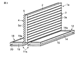
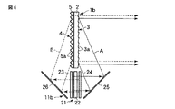
図3及び図4はこの発明の第2の実施例を示しており、図3は表示装置の斜視図、図4は前記表示装置の側面図である。なお、この実施例において、上記第1の実施例に対応するものには図に同符号を付し、同じのものについてはその説明を省略する。
(Second Embodiment)
3 and 4 show a second embodiment of the present invention. FIG. 3 is a perspective view of the display device, and FIG. 4 is a side view of the display device. In this embodiment, parts corresponding to those of the first embodiment are given the same reference numerals in the drawings, and the description of the same parts is omitted.
この実施例の表示装置は、半透過反射板2からなるスクリーン1aの前側領域の側方に第1の画像光出射部12を配置し、前記スクリーン1aの後側の領域(スクリーン1の後面に対向する領域)の側方に第2の画像光出射部18を配置した構成の画像光投影手段11aを備え、前記スクリーン1aの後面に、前記第2の画像光出射部18から投影された第2の画像光Bを前記スクリーン1aの法線付近の方向に屈折させて前記スクリーン1aに入射させる入射角制御手段4を設け、前記スクリーン1aの前面に、前記第1の画像光出射部12から投影された第1の画像光Aの反射方向を前記スクリーン1aを透過した前記第2の画像光Bの出射方向と実質的に一致させる反射方向制御手段3を設けたものである。
In the display device of this embodiment, the first image
この表示装置において、前記第1の画像光出射部12と前記スクリーン1aの前面の反射方向制御手段3は、上記第1の実施例と同じものであり、前記第2の画像光出射部18は、前記第1の画像光出射部12と実質的に同じ構成となっている。
In this display device, the first image
すなわち、前記第2の画像光出射部18は、前記スクリーン1aの左右方向に沿った方向の画面長さが前記スクリーン1aの利用領域(外周部を除く領域)の左右方向幅と実質的に同じに設定され、前記スクリーン1aの上下方向に沿った方向の画面長さが前記スクリーン1aの利用領域の上下方向幅を予め定めた比率で縮小した長さと実質的に同じに設定された横長矩形状の画面領域19aを有する第2の液晶表示素子19と、この第2の液晶表示素子19の一方の面に対向させて配置され、前記第2の液晶表示素子19の法線に対して前記スクリーン1a側に予め定めた角度傾いた方向(第2の液晶表示素子19の画面領域19aからスクリーン1aの利用領域に向かう方向)に出射光強度のピークが存在する指向性をもった照明光を出射する第2の面光源20とからなっており、前記第2の液晶表示素子19の画面領域19aの表示画像、つまり前記第2の面光源20から出射して前記第2の液晶表示素子19の複数の画素を透過した第2の画像光Bを、前記スクリーン1aの後面に向けて投影する。
That is, the second image
この第2の画像光出射部18は、前記スクリーン1aの後側領域の下側に、前記スクリーン1aを境にして前記第1の画像光出射部12と実質的に対称に、つまり前記スクリーン1aからの距離と前記スクリーン1に対する前記第2の画像光Bの出射角を前記第1の画像光出射部12と実質的に同じにして配置されている。
The second image
また、前記スクリーン1aの後面に設けられた入射角制御手段4は、透明フィルムの一方の面に複数の細長プリズム5aを、前記スクリーン1の前面に設けられた反射方向制御手段3の複数の細長傾斜面3aのピッチと同程度またはそれよりも小さいピッチ、或いは前記画素ピッチの数倍程度のピッチで互いに平行に形成したプリズムシート5からなっており、前記複数の細長プリズム5aの長さ方向を、前記反射方向制御手段3の複数の細長傾斜面3aの長さ方向、つまり、前記スクリーン1aの前記第2の画像光出射部18が配置された側の端縁(この実施例では下端縁)と実質的に平行な方向に向けて、前記細長プリズム5aの形成面とは反対面を前記半透過反射板2の後面に対向させて配置されている。
The incident angle control means 4 provided on the rear surface of the
すなわち、前記入射角制御手段4は、前記第2の画像光出射部18から投影された前記第2の画像光Bを、前記複数の細長プリズム5aにより屈折させて前記スクリーン1aの前記第1の画像光Aの投影領域に入射させるものであり、前記細長プリズム5aの2つの傾斜面の傾き角は、前記第2の画像光出射部18からの第2の画像光Bの投影角に応じて、前記第2の画像光出射部18から投影された前記第2の画像光Bを、前記スクリーン1aの法線付近の方向に屈折させて前記スクリーン1aに入射させるように設定されている。
In other words, the incident angle control means 4 refracts the second image light B projected from the second image
なお、この実施例では、複数の細長プリズム5aを形成したプリズムシート5を前記半透過反射板2の後面に設けているが、前記複数の細長プリズム5aは、前記半透過反射板2の後面に一体に形成してもよい。
In this embodiment, the
この実施例の表示装置は、半透過反射板2からなるスクリーン1aの前側領域の側方に第1の画像光出射部12を配置し、前記スクリーン1aの後側領域の側方に第2の画像光出射部18を配置した構成の画像光投影手段11aを備え、前記第2の画像光出射部18から投影された第2の画像光Bを、前記スクリーン1aの後面に設けられた前記入射角制御手段4により前記スクリーン1aの法線付近の方向に屈折させて前記スクリーン1aに入射させ、前記第1の画像光出射部12から投影された第1の画像光Aの反射方向を、前記スクリーン1aの前面に設けられた反射方向制御手段3により前記スクリーン1aを透過した前記第2の画像光Bの出射方向と実質的に一致させるようにしているため、奥行き感のある立体的な画像を前記スクリーン1aの前面の正面方向から観察させることができる。
In the display device of this embodiment, the first image
すなわち、この表示装置は、前記第1の画像光出射部12から投影され、前記スクリーン1aにより観察側に反射された第1の画像光Aからなる第1の画像が、前記スクリーン1aの前面位置にあるように見え、前記第2の画像光出射部18から投影され、前記スクリーン1の後面の入射角制御手段4により屈折されて前記スクリーン1aに入射し、この前記スクリーン1aを透過して観察側に出射した第2の画像光Bからなる第2の画像が、前記スクリーン1aの後面位置にあるように見え、前記第1と第2の両方の画像が重なった1つの画像に合成されて観察されるため、奥行き感のある立体的な画像を表示することができる。
That is, in this display device, the first image composed of the first image light A projected from the first image
そして、前記第1と第2の画像光A,Bは前記スクリーン1aの法線方向に出射するため、前記立体的な画像を前記スクリーン1aの前面の正面方向から観察させることができる。
Since the first and second image lights A and B are emitted in the normal direction of the
また、この表示装置は、前記画像光投影手段11aに、前記第1の画像光Aと第2の画像光Bの出射強度比を調整する手段を備えさせることにより、前記立体的な画像の奥行き感を任意に変化させることができる。
In addition, the display device includes the image
この実施例の表示装置においては、前記第2の画像光出射部18の液晶表示素子19の出射側偏光板(図示せず)の透過軸を、前記スクリーン1aの後面に設けられた入射角制御手段4の複数の細長プリズム5aの長さ方向と実質的に平行にするか、またはその方向に対して実質的に直交させ、前記第2の画像光出射部18から、前記細長プリズム5aの長さ方向と実質的に平行または直交する直線偏光からなる第2の画像光Bを前記スクリーン1aに向けて投影するようにするのが好ましく、このようにすることにより、前記第2の画像光出射部18からの第2の画像光Bを、前記複数の細長プリズム5aによりほとんどロス無く屈折させて効率良く前記スクリーン1aに入射させることができる。
In the display device according to this embodiment, the transmission axis of the exit-side polarizing plate (not shown) of the liquid
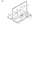
(第3の実施形態)
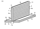
図5及び図6はこの発明の第3の実施例を示しており、図5は表示装置の斜視図、図6は前記表示装置の側面図である。なお、この実施例において、上記第1及び第2の実施例に対応するものには図に同符号を付し、同じのものについてはその説明を省略する。
(Third embodiment)
5 and 6 show a third embodiment of the present invention. FIG. 5 is a perspective view of the display device, and FIG. 6 is a side view of the display device. In this embodiment, parts corresponding to those in the first and second embodiments are given the same reference numerals in the drawings, and the description of the same parts is omitted.
この実施例の表示装置は、半透過反射板からなるスクリーン1bと、光の透過を制御する複数の画素がマトリックス状に配列した画面領域を有する1つの液晶表示素子22と前記液晶表示素子22の一方の面と他方の面とにそれぞれ対向させて配置され、前記液晶表示素子22に向けて照明光を出射し、前記液晶表示素子22からの出射光を透過させる第1と第2の面光源23,24とからなる画像光出射部21と、前記画像光出射部21の一方の面と他方の面とにそれぞれ対向させて配置された第1と第2の反射板25,26とにより構成された画像光投影手段11bとを備えたものである。
The display device according to this embodiment includes a
この表示装置において、前記画像光投影手段11bの画像光出射部21の液晶表示素子22は、上記第1の実施例の表示装置における第1の画像光出射部12の液晶表示素子14と実質的に同じ構成のものであり、前記スクリーン1bの左右方向に沿った方向の画面長さが前記スクリーン1bの利用領域(外周部を除く領域)の左右方向幅と実質的に同じに設定され、前記スクリーン1bの上下方向に沿った方向の画面長さが前記スクリーン1bの利用領域の上下方向幅を予め定めた比率で縮小した長さと実質的に同じに設定された横長矩形状の画面領域を有している。
In this display device, the liquid
また、前記画像光出射部21の第1と第2の面光源23,24はそれぞれ、前記液晶表示素子22の法線に沿った方向に出射光強度のピークが存在する指向性をもった照明光を出射するものであり、例えば、前記液晶表示素子22の画面領域の全域に対向する面積を有する板状の透明部材の一端面に光を入射させる入射端面が形成され、2つの板面の一方に前記入射端面から入射した光の出射端面が形成され、他方の板面に、前記入射端面から入射した光を前記板面と外気(空気)との界面により前記出射面に向けて全反射し、前記出射面から入射した光を透過させる反射/透過面が形成された導光板と、前記導光板の入射端面に対向させて配置され、前記入射端面に向けて光を出射するLED(発光ダイオード)等の複数の固体発光素子からなっている。
Further, the first and second
前記画像光出射部21は、前記第1と第2の面光源23,24からそれぞれ照明光を出射させ、前記液晶表示素子22の一方の面と他方の面からそれぞれ画像光を出射させるものであり、前記液晶表示素子22の第2の面光源24に対向する面から出射した第1の画像光Aを、図6に矢線で示したように前記第2の面光源24を透過させて出射し、前記液晶表示素子22の第1の面光源23に対向する面から出射した第2の画像光Bを、図6に破矢線で示したように前記第1の面光源23を透過させて出射する。
The image
この画像光出射部21は、前記スクリーン1bの前後面に設けられた反射方向制御手段3及び入射角制御手段4の細長傾斜面3a及び細長プリズム5aの長さ方向と実質的に平行な端縁の側方、例えば前記スクリーン1bの下側に、前記第1と第2の画像光A,Bの出射部面(第1と第2の面光源23,24の導光板の反射/透過面)を前記スクリーン1bの前後面と実質的に平行にし、且つ前記第1の画像光Aの出射方向を観察側に向け、前記第2の画像光Bの出射方向を前記観察側とは反対側に向けて配置されている。
The image
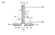
また、前記画像光投影手段11bの第1と第2の反射板25,26は、前記画像光出射部21からの前記第1と第2の画像光A,Bをそれぞれ前記スクリーン1bの前面と後面に向けて反射するものであり、第1の反射板25は、前記画像光出射部21からの前記第1の画像光Aの出射方向に、前記第1の画像光Aを前記スクリーン1bの前面に向けて反射するように、予め定めた傾き角で配置され、前記第2の反射板26は、前記画像光出射部21からの前記第2の画像光Bの出射方向に、前記画像光出射部21からの前記第2の画像光Bを前記スクリーン1bの後面に向けて反射するように、予め定めた傾き角で配置されている。
The first and
また、前記スクリーン1bは、上記第2の実施例のスクリーン1aと実質的に同じ構成のものであり、このスクリーン1bの後面に設けられた入射角制御手段4の複数の細長プリズム5aの2つの傾斜面の傾き角は、前記第2の反射板26により反射された第2の画像光Bの投影角に応じて、前記第2の画像光Bを前記スクリーン1bの法線付近の方向に屈折させて前記スクリーン1bに入射させるように設定され、また、前記スクリーン1bの前面に設けられた反射方向制御手段3の複数の細長傾斜面3aの傾き角は、前記第1の反射板25により反射された第1の画像光Aの投影角に応じて、前記第1の画像光Aを前記スクリーン1bを透過した前記第2の画像光Bの出射方向と実質的に同じ方向に反射する角度に設定されている。
The
さらに、この実施例では、前記画像光出射部21の液晶表示素子22の第2の画像光Bを出射側する側の偏光板(図示せず)の透過軸を、前記スクリーン1bの後面に設けられた入射角制御手段4の複数の細長プリズム5aの長さ方向と実質的に平行にするか、またはその方向に対して実質的に直交させることにより、前記画像光出射部21から前記細長プリズム5aの長さ方向と実質的に平行または直交する直線偏光からなる第2の画像光Bを前記スクリーン1bに向けて投影するようにし、前記第2の画像光出射部18からの第2の画像光Bを、前記複数の細長プリズム5aによりほとんどロス無く屈折させて効率良く前記スクリーン1bに入射させるようにしている。
Furthermore, in this embodiment, a transmission axis of a polarizing plate (not shown) on the side of the liquid
この実施例の表示装置は、1つの液晶表示素子22と、前記液晶表示素子22の一方の面と他方の面とにそれぞれ対向させて配置され、前記液晶表示素子22に向けて照明光を出射し、前記液晶表示素子22からの出射光を透過させる第1と第2の面光源23,24とからなり、前記第1の面光源23から出射して前記液晶表示素子22の複数の画素を透過した第1の画像光Aを前記第2の面光源24を透過させて出射し、前記第2の面光源24から出射して前記液晶表示素子22の複数の画素を透過した第2の画像光Bを前記第1の面光源23を透過させて出射する画像光出射部21と、前記画像光出射部21からの前記第1と第2の画像光A,Bをそれぞれ前記スクリーン1の前面と後面に向けて反射する第1と第2の反射板25,26とにより構成され、前記画像光出射部21を、前記スクリーン1bの側方に、前記第1の画像光Aの出射方向を観察側に向け、前記第2の画像光Bの出射方向を前記観察側とは反対側に向けて配置し、前記第1の反射板25を、前記画像光出射部21からの第1の画像光Aの出射方向に、前記第1の画像光Aを前記スクリーン1bの前面に向けて反射する傾き角で配置し、前記第2の反射板26を、前記画像光出射部21からの第2の画像光Bの出射方向に、前記第2の画像光Bを前記スクリーン1bの後面に向けて反射する傾き角で配置した画像光投影手段11bを備えたものであるため、前記画像光出射部21からの第1の画像光Aを前記第1の反射板25を介して前記スクリーン1bの前側領域の側方から前記スクリーン1bの前面に向けて投影し、前記画像光出射部21からの第2の画像光Bを前記第2の反射板26を介して前記スクリーン1bの後側領域の側方から前記スクリーン1bの後面に向けて投影することができる。
The display device of this embodiment is arranged to face one liquid
しかも、この表示装置は、画像光投影手段11の画像光出射部21を上記のような構成としているため、1つの液晶表示素子22により同一パターンの第1と第2の画像を表示し、その両方の画像光A,Bを前記スクリーン1bの前面と後面に向けて投影することができる。
In addition, since the image
そして、前記画像光出射部21から前記第1と第2の反射板25,26を介して前記スクリーン1bに投影された第1と第2の画像光A,Bのうち、前記スクリーン1bにより観察側に反射された第1の画像光Aからなる第1の画像は、前記スクリーン1bの前面位置にあるように見え、前記スクリーン1bの後面の入射角制御手段4により屈折されて前記スクリーン1bに入射し、この前記スクリーン1bを透過して観察側に出射した第2の画像光Bからなる第2の画像は、前記スクリーン1bの後面位置にあるように見え、前記第1と第2の両方の画像が重なった1つの画像に合成されて観察されるため、奥行き感のある立体的な画像を表示することができる。
Of the first and second image lights A and B projected from the image
また、この表示装置は、前記画像光投影手段11bに、前記第1の面光源23からの照明光の強度と前記第2の面光源24からの照明光の強度とを制御して前記第1の画像光Aと第2の画像光Bの出射強度比を調整する手段を備えさせることにより、前記立体的な画像の奥行き感を任意に変化させることができる。
In addition, the display device controls the first light source 23b by controlling the intensity of illumination light from the first
さらに、この表示装置は、前記スクリーン1bの後面に、前記画像光出射部21の一方の面から出射し、前記第2の反射板26を介して投影された前記第2の画像光Bを前記スクリーン1bの法線付近の方向に屈折させて前記スクリーン1bに入射させる入射角制御手段4を設け、前記スクリーン1bの前面に、前記画像光出射部21の他方の面から出射し、前記第1の反射板25を介して投影された前記第1の画像光Aの反射方向を前記スクリーン1bを透過した前記第2の画像光Bの出射方向と実質的に一致させる反射方向制御手段3を設けているため、前記奥行き感のある立体的な画像を前記スクリーン1bの前面の正面方向から観察させることができる。
Furthermore, the display device emits the second image light B emitted from one surface of the image
(第4の実施形態)
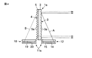
図7〜図9はこの発明の第4の実施例を示しており、図7は表示装置の斜視図、図8は前記表示装置の側面図である。なお、この実施例において、上記第1〜第3の実施例に対応するものには図に同符号を付し、同じのものについてはその説明を省略する。
(Fourth embodiment)
7 to 9 show a fourth embodiment of the present invention. FIG. 7 is a perspective view of the display device, and FIG. 8 is a side view of the display device. In this embodiment, the same reference numerals are given to the components corresponding to the first to third embodiments, and the description of the same components is omitted.
この実施例の表示装置は、互いに直交する反射軸6aと透過軸6b(図9参照)をもち、入射光の互いに直交する2つの直線偏光成分のうち、前記反射軸6aに平行な直線偏光成分を反射し、前記透過軸6bに平行な直線偏光成分を透過させる反射偏光板6からなるスクリーン1cと、上記第2の実施例の画像光投影手段11aとを備えたものであり、この表示装置では、前記画像光投影手段11aを、第1の画像光出射部12から前記反射偏光板6の反射軸6aと実質的に平行な直線偏光からなる第1の画像光Aを前記スクリーン1aの前面に向けて投影し、第2の画像光出射部18から前記反射偏光板6の透過軸6bと実質的に平行な直線偏光からなる第2の画像光Bを前記スクリーン1aの後面に向けて投影するように構成している。
The display device of this embodiment has a
また、この表示装置では、前記反射偏光板6からなるスクリーン1cの後面に、前記第2の画像光出射部18から投影された第2の画像光Bを前記スクリーン1cの法線付近の方向に屈折させて前記スクリーン1cに入射させる入射角制御手段7を設け、前記スクリーン1cの前面に、前記第1の画像光出射部12から投影された第1の画像光Aの反射方向を前記スクリーン1cを透過した前記第2の画像光Bの出射方向と実質的に一致させる反射方向制御手段9を設けている。
Further, in this display device, the second image light B projected from the second image
前記スクリーン1cの後面に設けられた入射角制御手段7は、透明フィルムの一方の面に複数の細長プリズム8aを互いに平行に形成したプリズムシート8からなっており、前記複数の細長プリズム8aの長さ方向を、前記スクリーン1cの前記第2の画像光出射部18が配置された側の端縁(この実施例では下端縁)と実質的に平行な方向に向けて、前記細長プリズム8aの形成面とは反対面を前記反射偏光板6の後面に対向させて配置されている。
The incident angle control means 7 provided on the rear surface of the
また、前記スクリーン1cの前面に設けられた反射方向制御手段9は、透明フィルムの一方の面に、細長形状を有し、その一側縁から他側縁に向かってフィルム面の外方に傾斜した複数の細長傾斜面10aを互いに平行に形成した傾斜面シート10からなっており、前記複数の細長傾斜面10aの長さ方向を、前記スクリーン1cの前記第1の画像光出射部12が配置された側の端縁(この実施例では下端縁)と実質的に平行、つまり前記入射角制御手段7の複数の細長プリズム8aの長さ方向と実質的に平行にし、且つ前記複数の細長傾斜面10aの傾斜方向を、前記第1の画像光出射部12の配置側に対向する側からその反対側に向かってスクリーン前面方向に傾斜する方向に合わせて、前記細長傾斜面10aの形成面とは反対面を前記反射偏光板6の前面に対向させて配置されている。
The reflection direction control means 9 provided on the front surface of the
さらに、前記入射角制御手段7の複数の細長プリズム8aの2つの傾斜面の傾き角は、前記第2の画像光出射部18からの第2の画像光Bの投影角に応じて、前記第2の画像光Bを反射偏光板6からなるスクリーン1cの法線付近の方向に屈折させて前記スクリーン1cに入射させるように設定されており、また、前記反射方向制御手段9の複数の細長傾斜面10aの傾き角は、前記第1の画像光出射部12からの第1の画像光Aの投影角に応じて、前記第1の画像光Aを前記スクリーン1cの法線に対する角度が小さくなる方向に屈折させてスクリーン1cに入射させ、前記反射偏光板6により反射された前記第1の画像光Aを、前記反射偏光板6を透過した前記第2の画像光Bの出射方向と実質的に同じ方向に出射させるように設定されている。
Further, the inclination angles of the two inclined surfaces of the plurality of
図9は、前記反射偏光板6の反射軸6a及び透過軸6bの向きと、前記画像光投影手段11aの第1及び第2の画像光出射部12,18からの第1及び第2の画像光(直線偏光)A,Bの偏光面の向きを示す模式図である。
FIG. 9 shows the orientation of the
図9のように、この実施例では、前記反射偏光板6の反射軸6aと透過軸6bの一方、例えば反射軸6aを、前記スクリーン1cの後面に設けられた入射角制御手段7の複数の細長プリズム8aの長さ方向と実質的に平行にし、前記第1の画像光出射部12の液晶表示素子14の出射側偏光板(図示せず)の透過軸aを、前記反射偏光板6の反射軸6aと実質的に平行にし、前記第2の画像光出射部18の液晶表示素子19の出射側偏光板(図示せず)の透過軸bを、前記第1の画像光出射部12の液晶表示素子14の出射側偏光板の透過軸aの方向に対して実質的に直交させることにより、前記第1の画像光出射部12から、前記反射偏光板6の反射軸6aと実質的に平行な直線偏光Sからなる第1の画像光Aを前記スクリーン1aの前面に向けて投影し、前記第2の画像光出射部18から、前記反射偏光板6の透過軸6bと実質的に平行な直線偏光Pからなる第2の画像光Bを前記スクリーン1aの後面に向けて投影するようにするとともに、前記第2の画像光出射部18からの第2の画像光Bを、前記入射角制御手段7の複数の細長プリズム8aによりほとんどロス無く屈折させて効率良く前記反射偏光板6に入射させるようにしている。
As shown in FIG. 9, in this embodiment, one of the
なお、前記反射偏光板6の反射軸6aと透過軸6bの向きと、前記第1と第2の画像光出射部12,18の液晶表示素子14,19の出射側偏光板の透過軸a,bの向きは、図9の向きに対して90度ずれた方向にしてもよく、その場合も、前記第2の画像光出射部18からの第2の画像光Bを、前記入射角制御手段7の複数の細長プリズム8aによりほとんどロス無く屈折させて効率良く前記反射偏光板6に入射させることができる。
Note that the orientation of the
この実施例の表示装置は、互いに直交する反射軸6aと透過軸6bをもち、入射光の互いに直交する2つの直線偏光成分のうち、前記反射軸6aに平行な直線偏光成分を反射し、前記透過軸6bに平行な直線偏光成分を透過させる反射偏光板6からなるスクリーン1cを備え、前記画像光投影手段11aを、前記反射偏光板6の反射軸6aと実質的に平行な直線偏光からなる第1の画像光Aを前記スクリーン1cの前面に向けて投影し、前記反射偏光板6の透過軸6bと実質的に平行な直線偏光からなる第2の画像光Bを前記スクリーン1cの後面に向けて投影するように構成しているため、前記スクリーン1cにその前面から入射した前記第1の画像光Aを観察側に反射し、前記スクリーン1cにその後面から入射した前記第2の画像光Bを透過させて前記観察側に出射することができる。
The display device of this embodiment has a
そして、前記第1と第2の画像光出射部12,18から前記スクリーン1cに投影された第1と第2の画像光A,Bのうち、前記スクリーン1cにより観察側に反射された第1の画像光Aからなる第1の画像は、前記スクリーン1cの前面位置にあるように見え、前記スクリーン1cの後面の入射角制御手段7により屈折されて前記スクリーン1cに入射し、この前記スクリーン1cを透過して観察側に出射した第2の画像光Bからなる第2の画像は、前記スクリーン1の後面位置にあるように見え、前記第1と第2の両方の画像が重なった1つの画像に合成されて観察されるため、奥行き感のある立体的な画像を表示することができる。
Of the first and second image lights A and B projected from the first and second image
さらに、この表示装置は、前記スクリーン1cの後面に、前記第1の画像光出射部12から投影された前記第2の画像光Bを前記スクリーン1cの法線付近の方向に屈折させて前記スクリーン1cに入射させる入射角制御手段7を設け、前記スクリーン1cの前面に、前記第2の画像光出射部18から出射し、前記第1の反射板25により反射されて前記スクリーン1cの前面に投影された前記第1の画像光Aの反射方向を前記スクリーン1cを透過した前記第2の画像光Bの出射方向と実質的に一致させる反射方向制御手段9を設けているため、前記奥行き感のある立体的な画像を前記スクリーン1cの前面の正面方向から観察させることができる。
Further, the display device refracts the second image light B projected from the first image
(他の実施形態)
なお、上記第4の実施例の表示装置は、反射偏光板6からなるスクリーン1cと、上記第2の実施例の画像光投影手段11aとを備えたものであるが、反射偏光板6からなるスクリーン1cと、上記第1の実施例の画像光投影手段11または上記第2の実施例の画像光投影手段11bとを組合わせても、同様な効果を得ることができる。
(Other embodiments)
The display device of the fourth embodiment is provided with the
また、上記第1、第2及び第4の実施例では、画像光投影手段11,11aの第1と第2の画像光出射部12,13,18を、液晶表示素子14,16,19と面光源15,17,19とにより構成しているが、前記画像光出射部12,13,18は、例えばEL(エレクトロルミネッセンス)表示素子等の自発光表示素子により構成してもよい。
In the first, second, and fourth embodiments, the first and second image
さらに、上記第3の実施例の画像光投影手段11bは、1つの液晶表示素子22と第1と第2の面光源23,24とからなる画像光出射部21を備えたものであるが、前記画像光出射部21は、前記EL表示素子等の2枚の自発光表示素子をそれぞれの画像光出射面を反対方向に向けて配置した構成としてもよい。
Further, the image
1,1a,1b,1c…スクリーン、2…半透過反射板、6…反射偏光板、3,9…反射方向制御手段、4,7…入射角制御手段、11,11a,11b…画像光投影手段、12,13,18,21…画像光出射部、14,16,19,22…液晶表示素子、14a,16a,19a…画面領域、15,17,20,23,24…面光源、A…第1の画像光、B…第2の画像光。
DESCRIPTION OF
Claims (5)
第1と第2の画像光を出射し、前記第1の画像光を、前記スクリーンの前側から前記スクリーンの前面に向けて投影し、前記第2の画像光を、前記スクリーンの後側から前記スクリーンの後面に向けて前記スクリーンの前記第1の画像光の投影領域に入射させるように投影する画像光投影手段とを備え、
画像光投影手段は、
光の透過を制御する複数の画素をマトリックス状に配列した画面領域を有する1つの液晶表示素子と、前記液晶表示素子の一方の面と他方の面とにそれぞれ対向させて配置され、前記液晶表示素子に向けて照明光を出射し、前記液晶表示素子からの出射光を透過させる第1と第2の面光源とからなり、前記液晶表示素子の一方の面と他方の面からそれぞれ画像光を出射し、前記液晶表示素子の前記第2の面光源に対向する面から出射した第1の画像光を前記第2の面光源を透過させて出射し、前記液晶表示素子の前記第1の面光源に対向する面から出射した第2の画像光を前記第1の面光源を透過させて出射する画像光出射部と、
前記画像光出射部からの前記第1と第2の画像光をそれぞれスクリーンの前面と後面に向けて反射する第1と第2の反射板とを備えており、
前記画像光出射部は、前記スクリーンの側方に、前記第1の画像光の出射方向を前記スクリーンの前側方向に向け、前記第2の画像光の出射方向を前記スクリーンの後側方向に向けて配置され、
前記第1の反射板は、前記画像光出射部からの前記第1の画像光の出射方向に、前記第1の画像光を前記スクリーンの前面に向けて反射するように配置され、前記第2の反射板は、前記画像光出射部からの前記第2の画像光の出射方向に、前記第2の画像光を前記スクリーンの後面に向けて反射するように配置されていることを特徴とする表示装置。 It has a front surface and a rear surface that are opposite to each other, and is arranged with the front surface facing the observation side, reflects light incident from the front surface to the observation side, and transmits light incident from the rear surface to transmit the observation. A screen exiting to the side,
The first and second image lights are emitted, the first image light is projected from the front side of the screen toward the front surface of the screen, and the second image light is projected from the rear side of the screen. Image light projecting means for projecting to enter the projection area of the first image light on the screen toward the rear surface of the screen ,
The image light projection means
One liquid crystal display element having a screen region in which a plurality of pixels for controlling the transmission of light are arranged in a matrix, and one liquid crystal display element and one surface of the liquid crystal display element are arranged to face each other, and the liquid crystal display It comprises first and second surface light sources that emit illumination light toward the element and transmit light emitted from the liquid crystal display element. Image light is emitted from one surface and the other surface of the liquid crystal display element, respectively. The first image light emitted from the surface facing the second surface light source of the liquid crystal display element is emitted through the second surface light source, and the first surface of the liquid crystal display element is emitted. An image light emitting unit for emitting the second image light emitted from the surface facing the light source through the first surface light source;
Comprising first and second reflecting plates for reflecting the first and second image lights from the image light emitting section toward the front and rear surfaces of the screen, respectively.
The image light emitting unit directs the emission direction of the first image light toward the front side of the screen and the emission direction of the second image light toward the rear side of the screen toward the side of the screen. Arranged,
The first reflection plate is arranged to reflect the first image light toward the front surface of the screen in the emission direction of the first image light from the image light emission unit, and the second reflection plate. The reflection plate is arranged to reflect the second image light toward the rear surface of the screen in the emission direction of the second image light from the image light emission unit. Display device.
Priority Applications (1)
| Application Number | Priority Date | Filing Date | Title |
|---|---|---|---|
| JP2005133571A JP4792805B2 (en) | 2005-04-28 | 2005-04-28 | Display device |
Applications Claiming Priority (1)
| Application Number | Priority Date | Filing Date | Title |
|---|---|---|---|
| JP2005133571A JP4792805B2 (en) | 2005-04-28 | 2005-04-28 | Display device |
Publications (2)
| Publication Number | Publication Date |
|---|---|
| JP2006309017A JP2006309017A (en) | 2006-11-09 |
| JP4792805B2 true JP4792805B2 (en) | 2011-10-12 |
Family
ID=37475958
Family Applications (1)
| Application Number | Title | Priority Date | Filing Date |
|---|---|---|---|
| JP2005133571A Expired - Fee Related JP4792805B2 (en) | 2005-04-28 | 2005-04-28 | Display device |
Country Status (1)
| Country | Link |
|---|---|
| JP (1) | JP4792805B2 (en) |
Families Citing this family (4)
| Publication number | Priority date | Publication date | Assignee | Title |
|---|---|---|---|---|
| US8446339B2 (en) | 2007-03-30 | 2013-05-21 | Pioneer Corporation | Image display device |
| JP6670326B2 (en) * | 2015-12-25 | 2020-03-18 | 富士フイルム株式会社 | Transparent screen |
| JP6633973B2 (en) * | 2016-05-30 | 2020-01-22 | 日華化学株式会社 | Screen film and screen |
| JP7488307B2 (en) | 2022-10-12 | 2024-05-21 | シャープディスプレイテクノロジー株式会社 | Display device |
Family Cites Families (3)
| Publication number | Priority date | Publication date | Assignee | Title |
|---|---|---|---|---|
| JP3521930B2 (en) * | 1993-05-11 | 2004-04-26 | セイコーエプソン株式会社 | Pseudo three-dimensional liquid crystal display |
| JP3022558B1 (en) * | 1998-05-21 | 2000-03-21 | 日本電信電話株式会社 | Three-dimensional display method and device |
| JP2004102003A (en) * | 2002-09-11 | 2004-04-02 | Asahi Glass Co Ltd | Liquid crystal display |
-
2005
- 2005-04-28 JP JP2005133571A patent/JP4792805B2/en not_active Expired - Fee Related
Also Published As
| Publication number | Publication date |
|---|---|
| JP2006309017A (en) | 2006-11-09 |
Similar Documents
| Publication | Publication Date | Title |
|---|---|---|
| JP4655465B2 (en) | Surface light source and liquid crystal display device | |
| US8714804B2 (en) | Backlight assembly and display apparatus having the same | |
| US8139024B2 (en) | Illuminator for emitting at least two lights having directivity and display apparatus using same | |
| CN100454110C (en) | Surface light source and liquid crystal display device | |
| JP2007155783A (en) | Liquid crystal display | |
| US9235055B2 (en) | Light source assembly and display apparatus having the same | |
| JP2007066555A (en) | Surface light source and liquid crystal display device | |
| JP4608947B2 (en) | Liquid crystal display device | |
| TW201719250A (en) | Display apparatus | |
| JP2011013688A (en) | Liquid crystal display device | |
| JP4483233B2 (en) | Surface light source and liquid crystal display device | |
| JP4525612B2 (en) | Display device | |
| JP4433724B2 (en) | Stereoscopic image display device | |
| JP4792805B2 (en) | Display device | |
| JP5034590B2 (en) | Display device | |
| JP4720207B2 (en) | Liquid crystal display device | |
| JP4622509B2 (en) | Liquid crystal display device | |
| US7623189B2 (en) | Stereoscopic image display device comprising transmissive liquid crystal display element | |
| JP4483756B2 (en) | Surface light source and liquid crystal display device | |
| JP5397334B2 (en) | Driving method of display device | |
| TWI509327B (en) | Backlight module, display apparatus, and displaying method | |
| JP2008071856A (en) | Light source, illuminator, liquid crystal device, and electronic apparatus | |
| JP2006234917A (en) | Liquid crystal display |
Legal Events
| Date | Code | Title | Description |
|---|---|---|---|
| A621 | Written request for application examination |
Free format text: JAPANESE INTERMEDIATE CODE: A621 Effective date: 20080424 |
|
| A977 | Report on retrieval |
Free format text: JAPANESE INTERMEDIATE CODE: A971007 Effective date: 20110128 |
|
| A131 | Notification of reasons for refusal |
Free format text: JAPANESE INTERMEDIATE CODE: A131 Effective date: 20110201 |
|
| A521 | Request for written amendment filed |
Free format text: JAPANESE INTERMEDIATE CODE: A523 Effective date: 20110302 |
|
| TRDD | Decision of grant or rejection written | ||
| A01 | Written decision to grant a patent or to grant a registration (utility model) |
Free format text: JAPANESE INTERMEDIATE CODE: A01 Effective date: 20110628 |
|
| A01 | Written decision to grant a patent or to grant a registration (utility model) |
Free format text: JAPANESE INTERMEDIATE CODE: A01 |
|
| A61 | First payment of annual fees (during grant procedure) |
Free format text: JAPANESE INTERMEDIATE CODE: A61 Effective date: 20110711 |
|
| R150 | Certificate of patent or registration of utility model |
Free format text: JAPANESE INTERMEDIATE CODE: R150 Ref document number: 4792805 Country of ref document: JP Free format text: JAPANESE INTERMEDIATE CODE: R150 |
|
| FPAY | Renewal fee payment (event date is renewal date of database) |
Free format text: PAYMENT UNTIL: 20140805 Year of fee payment: 3 |
|
| S111 | Request for change of ownership or part of ownership |
Free format text: JAPANESE INTERMEDIATE CODE: R313113 |
|
| R350 | Written notification of registration of transfer |
Free format text: JAPANESE INTERMEDIATE CODE: R350 |
|
| R250 | Receipt of annual fees |
Free format text: JAPANESE INTERMEDIATE CODE: R250 |
|
| R250 | Receipt of annual fees |
Free format text: JAPANESE INTERMEDIATE CODE: R250 |
|
| R250 | Receipt of annual fees |
Free format text: JAPANESE INTERMEDIATE CODE: R250 |
|
| R250 | Receipt of annual fees |
Free format text: JAPANESE INTERMEDIATE CODE: R250 |
|
| R250 | Receipt of annual fees |
Free format text: JAPANESE INTERMEDIATE CODE: R250 |
|
| R250 | Receipt of annual fees |
Free format text: JAPANESE INTERMEDIATE CODE: R250 |
|
| R250 | Receipt of annual fees |
Free format text: JAPANESE INTERMEDIATE CODE: R250 |
|
| R250 | Receipt of annual fees |
Free format text: JAPANESE INTERMEDIATE CODE: R250 |
|
| LAPS | Cancellation because of no payment of annual fees |