JP4792244B2 - Freezing bag thawing device - Google Patents
Freezing bag thawing device Download PDFInfo
- Publication number
- JP4792244B2 JP4792244B2 JP2005165635A JP2005165635A JP4792244B2 JP 4792244 B2 JP4792244 B2 JP 4792244B2 JP 2005165635 A JP2005165635 A JP 2005165635A JP 2005165635 A JP2005165635 A JP 2005165635A JP 4792244 B2 JP4792244 B2 JP 4792244B2
- Authority
- JP
- Japan
- Prior art keywords
- bag
- swing
- thawing
- freezing
- freezing bag
- Prior art date
- Legal status (The legal status is an assumption and is not a legal conclusion. Google has not performed a legal analysis and makes no representation as to the accuracy of the status listed.)
- Expired - Lifetime
Links
Images


Landscapes
- Medical Preparation Storing Or Oral Administration Devices (AREA)
- Freezing, Cooling And Drying Of Foods (AREA)
Description
本発明は、医薬品等の所定の液体が封入されて凍結された凍結バッグの解凍装置に関する。
The present invention relates to solutions KoSo location of frozen bags predetermined liquid such as pharmaceuticals are frozen are enclosed.
医薬品、医薬品原料、血液、食品等の所定の液体を封入でき、かつ柔軟性を有した平坦なバッグが知られている。この種のバッグに封入された液体はバッグと一緒に凍結された状態で保管されることがある。凍結保管された内容物を使用するには、液体が封入されて凍結されたバッグ(凍結バッグ)の事前の解凍が必要となる。特に、内容物が温度変化や高温に弱い場合には、急激な解凍によって内容物の変成を生じる場合がある。そのため、凍結バッグを室内に放置して自然解凍することも行われるが、これでは解凍までの時間が長引く。そこで、凍結バッグを温度調整可能な一対のヒータで挟んだ状態でプレートに設置し、その凍結バッグをヒータで加熱しながらプレートを水平方向に旋回させることにより、内容物の変成を防止しつつ凍結バッグを解凍する方法及びその方法を実現する装置が知られている(特許文献1参照)。 There are known flat bags that can enclose predetermined liquids such as pharmaceuticals, pharmaceutical raw materials, blood, foods, etc., and have flexibility. The liquid enclosed in this type of bag may be stored in a frozen state together with the bag. In order to use the contents stored in a frozen state, it is necessary to thaw a bag (frozen bag) in which a liquid is enclosed and frozen. In particular, when the contents are vulnerable to temperature changes or high temperatures, the contents may be transformed by rapid thawing. For this reason, the freezing bag is left in the room and naturally thawed, but this takes a long time to thaw. Therefore, the freezing bag is placed on a plate with a pair of temperature-adjustable heaters, and the freezing bag is frozen while the freezing bag is heated by the heater while rotating the plate in the horizontal direction while preventing the contents from being transformed. A method for thawing a bag and an apparatus for realizing the method are known (see Patent Document 1).
上記の方法では、凍結バッグの内容物の加熱による変成を防止するため、解凍時の温度管理が必須となり、更に内容物に応じて温度条件の設定を変更する必要が生じる。そのため、この方法を実現する装置の構成が複雑になるおそれがある。また、内容物によっては、解凍時のヒータによる加熱を忌避すべき場合もあるので、このような内容物が充填された凍結バッグに対しては上記の解凍方法を使用できず適用範囲が制限される。 In the above method, in order to prevent the contents of the freezing bag from being transformed by heating, temperature management at the time of thawing is indispensable, and it is necessary to change the setting of the temperature condition according to the contents. Therefore, there is a possibility that the configuration of the apparatus that realizes this method may be complicated. In addition, depending on the contents, there is a case where heating by a heater at the time of thawing should be avoided, so the above thawing method cannot be used for a frozen bag filled with such contents, and the application range is limited. The
そこで、本発明は、凍結バッグの内容物の変成を防止しつつ簡素な構成で解凍時間を短縮でき、しかも汎用性が高い凍結バッグの解凍装置を提供することを目的とする。
Accordingly, the present invention can shorten the defrosting time with a simple structure while preventing the modified contents of the freezing bag, yet an object to provide a solution KoSo location of versatile freezing bag.
以下、本発明の凍結バッグの解凍装置について説明する。なお、本発明の理解を容易にするために添付図面の参照符号を括弧書きにて付記するが、それにより本発明が図示の形態に限定されるものではない。
The following describes solutions KoSo location freezing bag according to the present invention. In order to facilitate understanding of the present invention, reference numerals in the accompanying drawings are appended in parentheses, but the present invention is not limited to the illustrated embodiment.
本発明の凍結バッグの解凍装置は、フレーム(7)と、所定の液体が封入されて凍結された凍結バッグ(C)を載せることが可能で、かつ所定の軸線(CL)を中心として回転可能に前記フレームに取付けられた揺動部材(8)が鉛直方向に複数段配置された部材群(8…8)と、前記揺動部材を前記軸線を中心として鉛直方向に揺動させる駆動装置(9)と、を備え、前記部材群のうち互いに隣接する揺動部材が連動して揺動するように連結部材(17)で連結され、かつ前記駆動装置が前記部材群のうちの一つの揺動部材を鉛直方向に揺動させることにより、上述した課題を解決する(請求項1)。この解凍装置によれば、揺動部材に凍結バッグを載せることにより、凍結バッグの内容物の表面が解凍し始めて、バッグ内に液体と凍結状態の固体とが併存する状態になったときには、凍結状態の固体が揺動に応じてバッグ内で移動するため、バッグ内に対流が起こる。これにより凍結バッグの解凍が促進されるので、解凍時間を短縮できる。また、一度に解凍できる凍結バッグの個数が増えるので、効率的な解凍作業が実現できる。駆動装置が駆動する一つの揺動部材から他の揺動部材に連結部材を介して動力が伝達されて全ての揺動部材が一緒に揺動するので、各揺動部材に対して別々の駆動装置を設ける態様に比べて、装置構成を簡素化できコストの上昇を抑えることができる。
The freezing bag thawing device according to the present invention can mount a frame (7) and a frozen bag (C) frozen by sealing a predetermined liquid, and can rotate about a predetermined axis (CL). A group of members (8... 8) in which swing members (8) attached to the frame are arranged in a plurality of stages in the vertical direction, and a drive device for swinging the swing members in the vertical direction about the axis. 9), and the rocking members adjacent to each other among the group of members are coupled by a coupling member (17) so that the rocking members interlock with each other. the Rukoto to oscillate the moving member in the vertical direction, to solve the problems described above (claim 1). According to this thawing device, when the freezing bag is placed on the rocking member, the surface of the contents of the freezing bag starts to thaw, and when the liquid and the frozen solid coexist in the bag , the freezing bag is frozen. Since the solid in the state moves in the bag in response to the swing, convection occurs in the bag. As a result, the thawing of the frozen bag is promoted, so that the thawing time can be shortened. In addition, since the number of freezing bags that can be thawed at a time increases, an efficient thawing operation can be realized. Power is transmitted from one oscillating member driven by the drive device to the other oscillating member via the connecting member, and all the oscillating members oscillate together, so that each oscillating member is driven separately. Compared with the mode in which the apparatus is provided, the apparatus configuration can be simplified and the increase in cost can be suppressed.
本発明の解凍装置において、前記軸線が水平方向に延びるようにして前記揺動部材の中央部に設定されており、前記揺動部材には、前記凍結バッグを載せるためのトレー(13)が該軸線を跨る状態で着脱可能に設けられてもよい(請求項2)。この態様によれば、凍結バッグをトレーに載せたときに凍結バッグを横切るように揺動の軸線が位置することになる。そのため、凍結バッグの長手方向に沿った延長線上で、かつ凍結バッグから離れた位置に揺動の軸線が設定される形態よりも少ない変位で凍結バッグに同じ傾きを与えることができる。従って、揺動部材を揺動させるために必要なスペースが少なくて済み、装置構成をコンパクトにできる。また、トレーと揺動部材とが着脱できるので、トレーに凍結バッグを載せた状態で揺動部材に設置できる。そのため、凍結バッグを直接触れることなく解凍作業を行うことができるので、解凍作業における凍結バッグの取り扱いが容易になる。なお、この態様において、軸線を跨るとは、軸線がトレーを横切るように位置している状態を意味し、所定の軸線がトレーの鉛直上方、鉛直下方、又はトレー内部のいずれに位置していてもよい。
In the thawing device of the present invention, the axis is set at the center of the swinging member so as to extend in the horizontal direction, and the tray (13) for placing the freezing bag is placed on the swinging member. It may be provided so as to be detachable in a state of straddling the axis (Claim 2 ). According to this aspect, the axis of oscillation is positioned so as to cross the freezing bag when the freezing bag is placed on the tray. Therefore, the same inclination can be given to the freezing bag with a smaller displacement than the form in which the axis of oscillation is set on the extension line along the longitudinal direction of the freezing bag and away from the freezing bag. Therefore, the space required for swinging the swing member is small, and the apparatus configuration can be made compact. Further, since the tray and the swinging member can be attached and detached, the tray can be installed on the swinging member with the freezing bag placed on the tray. Therefore, the thawing operation can be performed without directly touching the freezing bag, so that the freezing bag can be easily handled in the thawing operation. In this aspect, straddling the axis means that the axis is positioned so as to cross the tray, and the predetermined axis is positioned vertically above, vertically below, or inside the tray. Also good.
本発明の解凍装置においては、揺動部材が鉛直方向に複数段配置されるので、凍結バッグの解凍中に揺動部材間の空間に冷気が滞留し易くなり解凍の進行が妨げられるおそれがある。従って、前記部材群の揺動部材間に形成される空間(S)の換気を強制的に実行可能な換気手段(18)を更に備えてもよい(請求項3)。これによって、当該空間の換気が強制的に行われるので冷気の滞留を防止できる。
Te decompressor odor of the present invention, since the swing member is a plurality of stages arranged in a vertical direction, possibly progress of cold air tends to stay thawing is prevented in the space between the swinging member during the freezing bag thawing is there. Therefore, you may further provide the ventilation means (18) which can perform the ventilation of the space (S) formed between the rocking | swiveling members of the said member group compulsorily (Claim 3 ). As a result, the space is forcibly ventilated, so that cold air can be prevented from staying.
本発明の解凍装置において、前記揺動部材は、前記トレーを複数個並べて設置可能に構成されてもよい(請求項4)。この場合、一つの揺動部材で処理できる凍結バッグの個数が増加するので、解凍作業の効率を更に向上できる。
In the thawing device of the present invention, the swinging member may be configured so that a plurality of the trays can be arranged side by side (Claim 4 ). In this case, since the number of freezing bags that can be processed by one rocking member increases, the efficiency of the thawing operation can be further improved.
本発明の解凍装置においては、揺動部材を揺動させる駆動装置の構成は如何なるものでもよいが、例えば、駆動装置が、駆動源(10)の回転運動を直線運動に変換して前記揺動部材に伝達する動力伝達機構(11)を備えてもよいし(請求項5)、駆動源の回転運動をギア、ベルト、チェーン等の回転伝達手段を利用して揺動部材に伝達するように駆動装置を構成してもよい。
In the thawing device of the present invention, any configuration of the drive device for swinging the swing member may be used. For example, the drive device converts the rotational motion of the drive source (10) into a linear motion to perform the swing motion. A power transmission mechanism (11) for transmitting to the member may be provided (Claim 5 ), and the rotational motion of the drive source may be transmitted to the swinging member using a rotational transmission means such as a gear, a belt, or a chain. You may comprise a drive device.
以上説明したように、本発明によれば、所定の液体が封入されて凍結された凍結バッグを所定の軸線を中心として鉛直方向に揺動できるので、凍結バッグの解凍が促進されて解凍時間を短縮できる。 As described above, according to the present invention, a frozen bag filled with a predetermined liquid and frozen can be swung in a vertical direction around a predetermined axis, so that the thawing of the frozen bag is promoted and the thawing time is increased. Can be shortened.
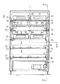
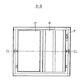
図1〜図4は本発明の実施形態に係る解凍装置を示している。図1は解凍装置の外観を示した斜視図、図2は図1の解凍装置の内部構造の正面図、図3は図2のA−A矢視図、図4は図2のB−B矢視図である。図1に示したように、解凍装置1は筐体2と作業者による各種の操作指示を受け付ける制御ユニット3とを備えている。筐体2は2つの扉4,4を有し左右対称に開閉可能である。筐体2を構成する扉4及び壁部5はそれぞれ多数の孔が形成されたパンチングメタル等の板状体で構成されて通気性が確保されるとともに、扉4,4が閉じられると外部からのアクセスが阻止されて安全性が確保される。図示していないが、天井面も壁部5と同様に構成されている。
1 to 4 show a thawing device according to an embodiment of the present invention. 1 is a perspective view showing the appearance of the thawing device, FIG. 2 is a front view of the internal structure of the thawing device in FIG. 1, FIG. 3 is a view taken along the line AA in FIG. 2, and FIG. It is an arrow view. As shown in FIG. 1, the
図2〜4に示すように、解凍装置1は筐体2の内側に配置されて装置の骨格をなすフレーム7と、鉛直方向(図2及び図3の上下方向)に、5段に亘って配置された揺動棚(揺動部材)8…8と、下から3段目の中央段の揺動棚8を鉛直方向に揺動させる駆動装置9と、を備えている。複数の揺動棚(部材群)8…8の各揺動棚8は水平方向に延びる軸線CLを中心に回転可能な状態で回転軸12を介してフレーム7に取り付けられている。また、各揺動棚8には凍結バッグC(図5参照)を載せるためのトレー13が軸線CLを跨るように着脱可能に設置される。但し、図2及び図3では、下から1段目と2段目の揺動棚8のトレー13が取り外された状態が示されている。図2に示すように、解凍装置1は一つの揺動棚8に対してトレー13を左右に2つ並べて設置可能である。また、トレー13の各揺動棚8に対する着脱を容易にし、かつ各揺動棚8を揺動させた際のトレー13の位置ずれを防止するため、各揺動棚8はトレー着脱機構81を備えている。
As shown in FIGS. 2 to 4, the
トレー着脱機構81は、揺動棚8に沿って延び、かつ蝶板84,84,84(図2)を介して揺動棚8にヒンジ結合された板状の押え部材82と、押え部材82の移動経路に出没可能なストッパ83,83と、を備え、トレー13の出し入れが可能な解放位置と揺動棚8に載せられたトレー13の移動を阻止する固定位置との間で切り替え可能である。図においては、上から1段目が解放位置にされ、2段目が固定位置にされている。解放位置は、ストッパ83が押え部材82の移動経路から待避する向きとされ、かつ押え部材82が揺動棚8から離れる方向(図3の左側)に待避された状態である。一方、固定位置は、押え部材82が鉛直方向に立ち上げられた状態でストッパ84が押え部材82の移動経路に干渉する向きとされて、押え部材82の移動が阻止された状態である。以上によってトレイ13の揺動棚8に対する着脱と揺動時の位置ずれ防止が実現される。
The tray attaching /
なお、トレー13の寸法は、解凍対象とする凍結バッグCがはみ出ない大きさに設定される。図5に示すように、本実施形態のトレー13の寸法(長さL×幅W×高さH)は、765mm×400mm×100mmである。また、トレー13の長手方向の両端面には長孔状の開口部13aが形成されて持ち運びが容易にされている。
The size of the
図3に示すように、駆動装置9は、電動機10と、この電動機10の回転運動を直線運動に変換して中央段の揺動棚8に伝達する動力伝達機構11を有している。動力伝達機構11は、電動機10の回転軸(不図示)に取り付けられた回転部材15と、この回転部材15と中央段の揺動棚8の端部とをリンク結合するアーム16とを有するクランク機構として構成される。互いに隣接する揺動棚8,8は、これらをリンク結合するリンクアーム(連結部材)17…17によって連結され、互いに連動して揺動できる。従って、電動機10が作動すると、動力伝達機構9から中央段の揺動棚8に入力された動力はリンクアーム17…17を介して残りの揺動棚8に伝達され、各揺動棚8が軸線CLを中心として鉛直方向に揺動する。なお、詳しい図示は略したが、動力伝達機構9は回転部材15とアーム16との連結位置を変更可能に構成されており、各揺動棚8の揺動の振幅を適宜に調整することができる。本実施形態では揺動の振幅を20mm〜70mmの範囲内で調整可能に構成されている。
As shown in FIG. 3, the
また、解凍装置1の背面側(図3の右側)には、各揺動棚8に対して一つずつファン(換気手段)18が設けられている。各ファン18は揺動棚8のやや上方に配置されて、揺動棚8間に形成される空間S、及び最上段の揺動棚8と天井面との間の空間S’の強制的な換気を行うことができる。各ファン18は各揺動棚8において均一な換気が行われるように作動される。なお、解凍装置1の内部から空気を排出、又は解凍装置1の外部から空気を供給するようにして換気してもよい。
Further, one fan (ventilating means) 18 is provided for each
電動機10及び各ファン18は制御ユニット3(図1)を介して交流電源に接続される。図1に示すように、制御ユニット3は主電源スイッチ、作動開始及び停止スイッチ、各揺動棚8の揺動の周期を設定する調整ボリューム等の操作部材が設けられた操作部3aと、この操作部3aに対する作業者の操作に応じて電動機10及び各ファン18の動作を制御する制御部(不図示)とを備えている。本実施形態では、調整ボリュームの設定に応じ、揺動の周期が5〜30(回/分)の範囲内で任意に選択できる。また、解凍装置1の作動中に扉4,4(図1)が開かれた場合には危険防止のため制御部によって作動が停止される。
The
次に、解凍装置1を用いた凍結バッグCの解凍方法について説明する。図5に示すように、解凍の対象となる凍結バッグCはたんぱく溶液(所定の液体)が無菌状態で封入され、トレー13に寝かされた状態で凍結されたものである。液体封入前のバッグは合成樹脂製のシートで形成された袋状のもので、20L(リットル)の液体の封入が可能である。バッグは液体の注入量によって形状が変化するが、水平面に寝かせた状態で扁平形状をなす。バッグの一端には液体注入用の管が取付けられていて、その管はトレー13の開口部13aを通って外部に引き出され、その管を介して液体が注入されてバッグに封入される。そして、液体が封入されたバッグはトレー13に載せたまま冷凍庫(不図示)で凍結されて保管される。
Next, a method for thawing the frozen bag C using the
解凍作業に際し、まず、解凍すべき凍結バッグCを用意し、所定の揺動棚8に載せる。本実施形態では、図5に示すように凍結バッグCがトレー13に載せられた状態で保管されているので、解凍装置1の扉4,4を開き、凍結バッグCを載せたトレー13を所定の揺動棚8に載せてトレー着脱機構81を固定位置とする。解凍装置1は各揺動棚8に2つのトレー13を設置できるので、最大10個の凍結バッグCを解凍できる。
In the thawing operation, first, a freezing bag C to be thawed is prepared and placed on a
次に、凍結バッグCを揺動棚8に載せた後に扉4,4を閉じ、制御ユニット3の操作部3aの主電源を入れるとともに、調整ボリュームを操作して揺動の周期を設定する。次いで、作動開始スイッチを操作して電動機10及び各ファン18をそれぞれ作動させ、換気を行いながら各揺動棚8を軸線CLを中心として鉛直方向に揺動させる。
Next, after placing the freezing bag C on the
作動の停止時期は、解凍装置1の作動開始からの経過時間又は作業者の目視による凍結バッグCの解凍状態に基づいて判断する。停止時期に至った場合には、制御ユニット3の停止スイッチを操作して解凍装置1の作動を停止させて解凍を終える。そして、扉4,4を開いて解凍済のバッグを(トレー13と一緒に)解凍装置1から取り出す。
The operation stop time is determined based on the elapsed time from the start of the operation of the
以上の解凍装置1を用いた解凍方法によれば、解凍装置1が設置された室内に放置して凍結バッグCを解凍させた場合に比べ、解凍時間が約50%短縮された。また、互いに同一の複数の凍結バッグCを同時に解凍する場合においても、ファン18によって冷気の滞留が抑制されて各揺動棚8の環境条件が揃うので、凍結バッグCの搭載場所によらず解凍時間が略均一となった。
According to the thawing method using the
本発明は以上の実施形態に限定されず、本発明の要旨の範囲内で種々の形態で実施できる。解凍対象となる凍結バッグの内容物に制限はなく、凍結して保管可能な液体であれば、医薬品、血液、食品等でもよい。従って、本発明は様々な凍結バッグの解凍に利用できる。 The present invention is not limited to the above embodiment, and can be implemented in various forms within the scope of the gist of the present invention. The contents of the freezing bag to be thawed are not limited, and may be a medicine, blood, food, etc. as long as it is a liquid that can be frozen and stored. Therefore, the present invention can be used for thawing various frozen bags.
上記の実施形態では凍結バッグCの取り扱いの容易性を考慮して、凍結バッグCを載せるためのトレー13と揺動棚8とを着脱可能な別体で構成したが、揺動棚8とトレー13とを一体化して本発明の揺動部材として機能させて、これに凍結バッグCを載せるようにしてもよいし、トレー13を省略してもよい。
In the above embodiment, considering the ease of handling of the freezing bag C, the
本発明の駆動装置は、上述した電動機10と、電動機10の回転運動を直線運動に変換して揺動棚8に伝達する動力伝達機構11とで実現する形態に制限されず、例えば、ギア、ベルト、チェーン等の回転伝達手段を利用して電動機10の回転運動を揺動棚8に伝達してもよいし、揺動棚8の回転軸を電動機10で直接駆動して揺動棚8を揺動させてもよい。また、動力伝達機構11が中央段の揺動棚8に動力を伝達する構成でなくてもよく、他の揺動棚8に入力しても構わない。
The drive device of the present invention is not limited to a mode realized by the above-described
1 解凍装置
7 フレーム
8 揺動棚(揺動部材)
9 駆動装置
10 電動機(駆動源)
11 動力伝達機構
13 トレー
17 リンクアーム(連結部材)
18 ファン(換気手段)
C 凍結バッグ
S 空間
CL 軸線(所定の軸線)
1
9 Drive
11
18 Fan (ventilation means)
C Freezing bag S Space CL Axis (predetermined axis)
Claims (5)
前記部材群のうち互いに隣接する揺動部材が連動して揺動するように連結部材で連結され、かつ前記駆動装置が前記部材群のうちの一つの揺動部材を鉛直方向に揺動させることを特徴とする凍結バッグの解凍装置。 A frame and a frozen bag sealed with a predetermined liquid can be placed thereon, and swing members attached to the frame are arranged in a plurality of stages in the vertical direction so as to be rotatable about a predetermined axis . A member group, and a drive device that swings the swinging member in the vertical direction around the axis ,
The swing members adjacent to each other in the member group are connected by a connecting member so as to swing in conjunction with each other, and the driving device swings one swing member in the member group in the vertical direction. decompressor of that frozen bag be said.
前記揺動部材には、前記凍結バッグを載せるためのトレーが当該軸線を跨る状態で着脱可能に設けられることを特徴とする請求項1に記載の凍結バッグの解凍装置。 It is set at the center of the swing member so that the axis extends in the horizontal direction,
Wherein the swing member, the decompressor freezing bag according to claim 1, tray for placing the freezing bag is characterized in that it is detachably provided in a state extending over the axis.
Priority Applications (1)
| Application Number | Priority Date | Filing Date | Title |
|---|---|---|---|
| JP2005165635A JP4792244B2 (en) | 2005-06-06 | 2005-06-06 | Freezing bag thawing device |
Applications Claiming Priority (1)
| Application Number | Priority Date | Filing Date | Title |
|---|---|---|---|
| JP2005165635A JP4792244B2 (en) | 2005-06-06 | 2005-06-06 | Freezing bag thawing device |
Publications (2)
| Publication Number | Publication Date |
|---|---|
| JP2006333841A JP2006333841A (en) | 2006-12-14 |
| JP4792244B2 true JP4792244B2 (en) | 2011-10-12 |
Family
ID=37554922
Family Applications (1)
| Application Number | Title | Priority Date | Filing Date |
|---|---|---|---|
| JP2005165635A Expired - Lifetime JP4792244B2 (en) | 2005-06-06 | 2005-06-06 | Freezing bag thawing device |
Country Status (1)
| Country | Link |
|---|---|
| JP (1) | JP4792244B2 (en) |
Families Citing this family (4)
| Publication number | Priority date | Publication date | Assignee | Title |
|---|---|---|---|---|
| DK200801639A (en) | 2008-11-21 | 2010-05-22 | Calvex As | Improvements in or relating to the thawing of raw milk |
| US8338756B2 (en) | 2008-12-08 | 2012-12-25 | Duke Manufacturing Co. | Rethermalizing apparatus |
| JP2013116068A (en) * | 2011-12-02 | 2013-06-13 | Hamamatsu Photonics Kk | Thawing container |
| US20240269040A1 (en) * | 2021-05-26 | 2024-08-15 | BioNTech SE | Device and method for accelerated thawing |
Family Cites Families (6)
| Publication number | Priority date | Publication date | Assignee | Title |
|---|---|---|---|---|
| DE3047784C2 (en) * | 1980-12-18 | 1982-10-21 | Forschungsgesellschaft für Biomedizinische Technik, 5100 Aachen | Method and device for heating suspensions or solutions frozen in a flat plastic bag |
| JPH037566A (en) * | 1989-06-03 | 1991-01-14 | Koresawa Tekkosho:Kk | Method and device for thawing frozen food |
| US6190913B1 (en) * | 1997-08-12 | 2001-02-20 | Vijay Singh | Method for culturing cells using wave-induced agitation |
| DK1196211T3 (en) * | 1999-05-28 | 2006-01-02 | Integrated Biosystems | Improved thawing of biopharmaceutical solutions using an oscillatory motion |
| JP2002034531A (en) * | 2000-07-26 | 2002-02-05 | Lf Laboratory Kk | Electric field processing method and electric field processing apparatus |
| JP4338168B2 (en) * | 2002-05-20 | 2009-10-07 | 株式会社前川製作所 | Frozen food thawing method and thawing device used in this thawing method |
-
2005
- 2005-06-06 JP JP2005165635A patent/JP4792244B2/en not_active Expired - Lifetime
Also Published As
| Publication number | Publication date |
|---|---|
| JP2006333841A (en) | 2006-12-14 |
Similar Documents
| Publication | Publication Date | Title |
|---|---|---|
| EP3360422B1 (en) | Machine for making and dispensing a liquid or semi-liquid product | |
| EP3360421A1 (en) | Machine for making and dispensing a liquid or semiliquid product | |
| CN206739713U (en) | A kind of thawing apparatus and refrigerator | |
| EP1510162A3 (en) | Food blending apparatus | |
| EP2839822A1 (en) | Defrosting device | |
| JP4792244B2 (en) | Freezing bag thawing device | |
| JP4997638B2 (en) | Frozen drug thawing device | |
| DE69701096T2 (en) | REFRIGERATED AND TROPICALIZED CONTAINERS FOR THE STORAGE AND TRANSPORTATION OF HEAT-SENSITIVE PRODUCTS | |
| US9003822B2 (en) | Apparatus for breaking ice clumps | |
| CN210785646U (en) | Dry type blood plasma thawing and heating device with swing mechanism | |
| JP4743838B2 (en) | Microwave continuous irradiation heating device | |
| CN207242725U (en) | Salmon feed device | |
| CN115368920A (en) | Internal heating type biomass cracking equipment | |
| CN216596394U (en) | Intelligent breakfast booth | |
| CN107397984A (en) | Anhydrous type dry blood plasma heats thawing instrument | |
| JP4676330B2 (en) | Mixing device using swing fulcrum type lever device | |
| EP4704589A1 (en) | Machine for preparing and dispensing granita | |
| CN221619232U (en) | Refrigerating and mixing integrated machine | |
| CN87102876A (en) | liquid dispenser | |
| CN213238085U (en) | Double-refrigerator device | |
| JP2003262458A (en) | Food heating-cooling system | |
| CN215675992U (en) | Portable on-vehicle medical fridge of remote control | |
| CN207566058U (en) | A kind of blood station blood platelet constant temperature oscillation storage box | |
| CN209893712U (en) | Refrigerator and freezer | |
| EP1772083A1 (en) | Multifunction roasting oven |
Legal Events
| Date | Code | Title | Description |
|---|---|---|---|
| A621 | Written request for application examination |
Free format text: JAPANESE INTERMEDIATE CODE: A621 Effective date: 20080123 |
|
| A977 | Report on retrieval |
Free format text: JAPANESE INTERMEDIATE CODE: A971007 Effective date: 20091110 |
|
| A131 | Notification of reasons for refusal |
Free format text: JAPANESE INTERMEDIATE CODE: A131 Effective date: 20100921 |
|
| A521 | Request for written amendment filed |
Free format text: JAPANESE INTERMEDIATE CODE: A523 Effective date: 20101117 |
|
| TRDD | Decision of grant or rejection written | ||
| A01 | Written decision to grant a patent or to grant a registration (utility model) |
Free format text: JAPANESE INTERMEDIATE CODE: A01 Effective date: 20110705 |
|
| A01 | Written decision to grant a patent or to grant a registration (utility model) |
Free format text: JAPANESE INTERMEDIATE CODE: A01 |
|
| A61 | First payment of annual fees (during grant procedure) |
Free format text: JAPANESE INTERMEDIATE CODE: A61 Effective date: 20110725 |
|
| FPAY | Renewal fee payment (event date is renewal date of database) |
Free format text: PAYMENT UNTIL: 20140729 Year of fee payment: 3 |
|
| R150 | Certificate of patent or registration of utility model |
Free format text: JAPANESE INTERMEDIATE CODE: R150 Ref document number: 4792244 Country of ref document: JP |
|
| R250 | Receipt of annual fees |
Free format text: JAPANESE INTERMEDIATE CODE: R250 |
|
| R250 | Receipt of annual fees |
Free format text: JAPANESE INTERMEDIATE CODE: R250 |
|
| R250 | Receipt of annual fees |
Free format text: JAPANESE INTERMEDIATE CODE: R250 |
|
| R250 | Receipt of annual fees |
Free format text: JAPANESE INTERMEDIATE CODE: R250 |
|
| R250 | Receipt of annual fees |
Free format text: JAPANESE INTERMEDIATE CODE: R250 |
|
| R250 | Receipt of annual fees |
Free format text: JAPANESE INTERMEDIATE CODE: R250 |
|
| R250 | Receipt of annual fees |
Free format text: JAPANESE INTERMEDIATE CODE: R250 |
|
| R250 | Receipt of annual fees |
Free format text: JAPANESE INTERMEDIATE CODE: R250 |
|
| EXPY | Cancellation because of completion of term |