JP4792183B2 - Wireless communication device - Google Patents
Wireless communication device Download PDFInfo
- Publication number
- JP4792183B2 JP4792183B2 JP2001282248A JP2001282248A JP4792183B2 JP 4792183 B2 JP4792183 B2 JP 4792183B2 JP 2001282248 A JP2001282248 A JP 2001282248A JP 2001282248 A JP2001282248 A JP 2001282248A JP 4792183 B2 JP4792183 B2 JP 4792183B2
- Authority
- JP
- Japan
- Prior art keywords
- antenna
- wireless communication
- main body
- whip
- whip antenna
- Prior art date
- Legal status (The legal status is an assumption and is not a legal conclusion. Google has not performed a legal analysis and makes no representation as to the accuracy of the status listed.)
- Expired - Fee Related
Links
- 230000005540 biological transmission Effects 0.000 description 16
- 230000008878 coupling Effects 0.000 description 5
- 238000010168 coupling process Methods 0.000 description 5
- 238000005859 coupling reaction Methods 0.000 description 5
- 230000005684 electric field Effects 0.000 description 4
- 239000012212 insulator Substances 0.000 description 3
- 230000005855 radiation Effects 0.000 description 3
- RYGMFSIKBFXOCR-UHFFFAOYSA-N Copper Chemical compound [Cu] RYGMFSIKBFXOCR-UHFFFAOYSA-N 0.000 description 2
- 230000005686 electrostatic field Effects 0.000 description 2
- 229910052802 copper Inorganic materials 0.000 description 1
- 239000010949 copper Substances 0.000 description 1
- 230000000694 effects Effects 0.000 description 1
- 230000003071 parasitic effect Effects 0.000 description 1
- 229920003002 synthetic resin Polymers 0.000 description 1
- 239000000057 synthetic resin Substances 0.000 description 1
Images

Landscapes
- Support Of Aerials (AREA)
Description
【0001】
【発明の属する技術分野】
本発明は、送信機、受信機または送受信機のような無線通信装置に関し、特にそれに使用されているアンテナに関する。
【0002】
【従来の技術】
携帯型の無線通信機では、それのデザインや携帯性の観点から、ケースの内部にアンテナを内蔵した内蔵アンテナを搭載することが増えている。しかし、内蔵型のアンテナを使用した無線通信機器では、アンテナ効率が悪く、近距離通信では問題がないが、遠距離通信を行う場合に、電波を良好に送受信することができない。この問題を解決するために、例えば特開平7−94923号公報には、内蔵アンテナを必要なときだけケースから引き出して使用するものが提案されている。
【0003】
【発明が解決しようとする課題】
しかし、近距離通信のみに使用するのであれば、本来、アンテナを引き延ばすための構成は不要である。一方、アンテナを引き延ばせなければ、通信可能距離は短くなってしまう。また、アンテナをケースから引き延ばせる構成とするためには、ケース内に複雑な構成が必要になる。
【0004】
本発明は、簡単な構成で、遠距離及び近距離通信が共に良好に行える無線通信機を提供することを目的とする。
【0005】
本発明による無線通信装置は、無線通信手段が内蔵された本体部を有している。無線通信手段としては、送信手段、受信手段または送受信手段のいずれかを使用することができる。本体部は携帯可能な大きさとすることができる。この本体部に直線状の第1アンテナが内蔵され、無線通信手段に給電点を介して接続されている。本体部の外部に設けた装着具を介して前記本体部の外部に直線状の第2アンテナが着脱自在に設けられている。第2アンテナは、第1アンテナに対してほぼ対向する位置にほぼ並行に配置され、第1アンテナと電界結合している。電界結合としては、放射電界による結合または正殿会による正殿結合のいずれかを使用することができる。第1アンテナの一端が前記給電点であり、第2アンテナは、前記本体部への装着状態において、第2アンテナの一端が第1アンテナの一端に対応する位置にあり、第2アンテナの他端は、本体部よりも突出している。
【0006】
本発明の一態様の無線通信装置では、近距離通信を行う場合には、第2アンテナを取り付けず、第1アンテナのみによって通信を行う。従って、本体部を携帯しながら使用する場合に、アンテナが嵩張ることがない。例えば本体部を特定の位置に固定して、遠距離通信を行う場合には、第2アンテナを本体部に装着する。このとき、第1アンテナと第2アンテナが電界結合する。第1アンテナと第2アンテナとを平行に配置しているので、最も電界結合が大きくなっている。従って、例えば通信手段が送信手段の場合、送信手段からの出力が第1アンテナから第2アンテナに供給され、第2アンテナから送信される。第2アンテナには、第1アンテナよりも長いものを使用しているので、第1アンテナよりも長い第2アンテナの方が電波の到達距離が長く、遠距離通信が可能である。なお、第2アンテナは無給電で、かつ第1アンテナに対して第2アンテナを電界結合されているので、第1アンテナと第2アンテナとを切り換えて、通信手段に接続する必要がない。従って、アンテナ切換回路等を本体部に設ける必要が無く、本体部内の構成を簡略化することができる。
【0008】
上記の態様の無線通信装置において、前記第1アンテナは、前記無線通信手段において使用する電波の波長の約1/4の奇数倍の長さを有し、前記第2アンテナは、前記波長の奇数倍または整数倍の長さを有しているものとすることができる。第1及び第2アンテナは、ホイップアンテナとすることができる。前記装着具を前記第2のアンテナの一端部に設けることができる。この場合、前記装着具は導電性であり、前記本体部内の接地電位点に接続されている。或いは、前記装着具を絶縁性とすることができる。この場合、前記第2のアンテナの両端が開放されている。また、前記第2のアンテナを前記第1のアンテナに対して向きを変更可能に設けることもできる。
【0010】
上記の態様の無線通信装置において、上述したのと同様に、第1アンテナを約1/4波長の奇数倍の長さの直線状アンテナとし、第2アンテナを約1/4の波長の長さの偶数倍の長さで、第1アンテナよりも長い直線状アンテナとするか、第2のアンテナを前記波長の約1/4の奇数倍の長さを有し、第1のアンテナよりも長く、一端が接地されたものとする。さらに、前記装着状態において第1及び第2のアンテナを、接近させて直交して配置する。
【0011】
これらのように構成した場合、両アンテナをなんら特別な素子を使用せずに、静電結合することができる。
【0012】
【発明の実施形態】
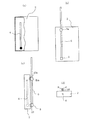
本発明の1実施形態の無線通信装置は、図1(a)乃至(d)に示すように本体部2を有している。この本体部2は、扁平な直方体状に形成され、携帯可能な大きさに形成されている。この本体部2内に、図示していないが、受信手段、送信手段または送受信手段が設けられている。
【0013】
本体部2には、第1のアンテナ、例えば直線状のアンテナ、具体的にはホイップアンテナ4が設けられている。このホイップアンテナ4は、送受信しようとする電波の波長λの約1/4の奇数倍の長さ、例えばλ/4を有し、本体部2内に配置されている無指向性のものである。様々な方向に電波を送受信する上から、無指向性のアンテナを第1アンテナとして使用することが望ましい。図1(a)に黒丸で示すように、ホイップアンテナ4の一端が給電点とされ、受信手段、送信手段または送受信手段に接続されている。
【0014】
従って、本体部2内に送信手段が設けられている場合、送信手段からの電流がホイップアンテナ4に流れ、ホイップアンテナ4から電波が放射される。アンテナの可逆性により、本体部内に受信手段が設けられている場合でも、上述したのと逆に、ホイップアンテナ4で電波が受信され、受信手段に電流が流れる。送受信手段の場合、送信手段と受信手段とが組み合わされたものであるので、詳細な説明は省略する。このように、ホイップアンテナ4単独で、内蔵アンテナとして機能する。
【0015】
本体部2の外部に着脱自在に、第2アンテナ、例えば直線状のアンテナ、具体的にはホイップアンテナ6が設けられている。ホイップアンテナ6は、両端が開放されたもので、装着状態においても、送信手段、受信手段または送受信手段とは直接に結合されて無く、無給電のものである。このホイップアンテナ6は、長さがλ/4の偶数倍で、ホイップアンテナ4よりも長い、例えば約λ/2で、本体部2に装着された状態においてホイップアンテナ4と平行にかつ接近した状態に配置されている。しかも、その先端部から約λ/4の長さの部分が本体部2よりも外方に位置している。第2のアンテナも無指向性アンテナとすることが望ましい。両者は、両者が静電結合するように接近させて配置されている。ホイップアンテナ6は、例えば本体部2を天井等に固定して使用する場合に、本体部2に装着される。このホイップアンテナ6としては、針金や銅線のような比較的低コストのものを使用できる。特に、天井裏等の外部から見えにくい場所に設置する場合、美観上の問題を考慮する必要がなく、針金や銅線等の安価なものを使用する。
【0016】
ホイップアンテナ6を使用する場合であって、送信手段が本体部2内に設けられていると、送信手段からホイップアンテナ4に電流が供給され、ホイップアンテナ4の周囲に非常に強い静電界が発生する。ホイップアンテナ6は、ホイップアンテナ4と非常に接近して配置されているので、ホイップアンテナ4による非常に強い静電界中に存在し、両者は強固に静電結合し、ホイップアンテナ4に流れた電流は、ホイップアンテナ6にも流れ、ホイップアンテナ6から空中に電波が放射される。この場合、ホイップアンテナ6が本体部2の外部にあるので、本体部2が電波の送受信の障害となることはなく、しかも、その長さがλ/2であり、約λ/4の部分が本体部2よりも外方に突出しているので、ホイップアンテナ4よりも電波の到達距離を長くすることができる。従って、ホイップアンテナ6を取り付けることによって、遠距離通信が可能となる。受信手段または送受信手段を使用する場合も同様であるので、詳細な説明は省略する。
【0017】
ホイップアンテナ6の着脱を自在とするために、図1(b)に示すように、ホイップアンテナ6の一端には、装着具8が一体に形成されている。この装着具8には、ホイップアンテナ6の長さ方向に垂直に伸びた円柱状の脚部10が形成されている。この脚部10が、本体部2の一面に形成した円形孔(図示せず)に挿入される。また、ホイップアンテナ6の中途にも同様な装着具8aが形成され、この装着具8aの脚部10aが、やはり本体部2の一面に形成した円形孔(図示せず)に挿入される。このように脚部10、10aを円形孔に挿入することによって、ホイップアンテナ6を本体部2に装着することができ、脚部10、10aを円形孔から抜くことによって、ホイップアンテナ6を本体部2から外すことができる。
【0018】
なお、装着具8、8aを絶縁体製とすることで、ホイップアンテナ6の両端を開放することができる。装着具8、8a及び脚部10、10aを導電性とし、脚部10、10aを本体部2内の接地電位点に接続し、装着具8、8a間の距離、及び脚部10、10a間の距離を、例えばλ/2とし、ホイップアンテナ6の全長をλ/2の整数倍(λ/4の偶数倍)とすることもできる。即ち、ホイップアンテナ6の全長をホイップアンテナ4よりも長く、且つλ/4の偶数倍の長さnとし、その一端と、その一端からλ/4の偶数倍の長さm(m<n)の箇所とで、ホイップアンテナ6を接地することもできる。
【0019】
本発明の参考例の無線通信装置を図2(a)、(b)に示す。この無線通信装置も、上記の実施形態の無線通信装置と同様に、扁平な直方体状の本体部2内に、λ/4の長さのホイップアンテナを有している。このホイップアンテナ4の一端が給電点とされて、本体部2内の受信手段、送信手段または送受信手段に接続されている。本体部2の外部に第2アンテナとして、λ/2の長さのホイップアンテナ6が着脱自在に設けられている。
【0020】
ホイップアンテナ6は、装着状態において、ホイップアンテナ4と直交するように配置されている。両者の距離は、両者が静電界結合するように接近させられている。ホイップアンテナ6は、ホイップアンテナ4の長さ方向の中央付近で、ホイップアンテナ4と交差している。このホイップアンテナ6は、本体部2の一面に間隔をあけて1つの直線に沿って取り付けられた2つの保持具12、12aによって本体部2に装着されている。これら保持具12、12aは、絶縁体、例えば可撓性を有する合成樹脂等によって形成され、本体部2の一面から立ち上がり、ホイップアンテナ6をそれの両側から把持するほぼY字状に形成されている。なお、ホイップアンテナ6は、装着状態において、それの長さ方向に沿って移動可能であり、ホイップアンテナ4との交差位置を変更することができる。
【0021】
この無線通信装置でも、本体部2を携帯する場合には、ホイップアンテナ6を取り付けずに、内蔵のホイップアンテナ4によって送信または受信を行う。また、この無線通信装置を天井等に固定して使用する場合、ホイップアンテナ6を保持具12、12を用いて本体部2に取り付ける。このとき、ホイップアンテナ4、6が静電結合し、第1の実施の形態の無線通信装置と同様にホイップアンテナ6から送信または受信が行われる。両ホイップアンテナ4、6を直交させているので、それぞれのホイップアンテナ4、6の放射インピーダンスが、もう1つのホイップアンテナの放射インピーダンスに対して干渉して無く、放射インピーダンスの影響を殆ど受けず、近接して両者を設けていても、結合損失が大きくなることがない。なお、送受信状態を良好にするために、ホイップアンテナ6をその長さ方向に沿って移動させても良い。
【0022】
上記実施形態及び参考例では、装着具8、8a、保持具12、12aを絶縁体製としたので、ホイップアンテナ6は両端開放型であり、λ/4の偶数倍の長さを持つものとした。しかし、ホイップアンテナ6の一端を固定するための装着具8、これが装着される脚部10、ホイップアンテナ6の一端を固定するための保持具12を、導電性として、脚部10、保持具12を、例えば本体部2内に形成した接地電位点に接続しておけば、ホイップアンテナ6の一端が接地されるので、ホイップアンテナ6の長さをλ/4の奇数倍とすることもできる。但し、この場合でも、ホイップアンテナ6の全長は、ホイップアンテナ4よりも長く選択する。
【0023】
上記実施形態及び参考例では、ホイップアンテナ4、6は、静電結合させたが、両ホイップアンテナの間隔を広げて、放射電界結合するように構成することもできる。
【0024】
【発明の効果】
以上のように、本発明によれば、第2のアンテナを本体部に対して着脱自在に設けたので、簡単な構成で、遠距離通信と近距離通信にそれぞれ対応した無線通信機を得ることができる。
【図面の簡単な説明】
【図1】 本発明の1実施形態の無線通信装置の第2アンテナを除去した状態の部分破断正面図、第2アンテナを取り付けた状態の正面図、側面図及び部分省略底面図である。
【図2】 本発明の参考例の無線通信装置の第2アンテナを除去した状態の部分破断正面図と取り付けた状態の正面図である。
【符号の説明】
2 本体部
4 ホイップアンテナ(第1アンテナ)
6 ホイップアンテナ(第2アンテナ)[0001]
BACKGROUND OF THE INVENTION
The present invention relates to wireless communication devices such as transmitters, receivers or transceivers, and more particularly to antennas used therein.
[0002]
[Prior art]
From the viewpoint of the design and portability of portable wireless communication devices, the use of built-in antennas with built-in antennas inside cases is increasing. However, in a wireless communication device using a built-in antenna, antenna efficiency is poor and there is no problem in short-distance communication, but radio waves cannot be transmitted and received satisfactorily when performing long-distance communication. In order to solve this problem, for example, Japanese Patent Laid-Open No. 7-94923 proposes a built-in antenna that is pulled out from the case and used only when necessary.
[0003]
[Problems to be solved by the invention]
However, if it is used only for near field communication, a configuration for extending the antenna is not necessary. On the other hand, if the antenna cannot be extended, the communicable distance is shortened. Moreover, in order to make the antenna extend from the case, a complicated structure is required in the case.
[0004]
An object of the present invention is to provide a wireless communication device that can easily perform both long-distance and short-distance communication with a simple configuration.
[0005]
The wireless communication apparatus according to the present invention has a main body in which wireless communication means is built. As the wireless communication means, any of transmission means, reception means, and transmission / reception means can be used. The main body can be portable. A first linear antenna is built in the main body, and is connected to the wireless communication means via a feeding point. A linear second antenna is detachably provided on the outside of the main body via a mounting tool provided on the outside of the main body. The second antenna is disposed substantially in parallel at a position substantially opposite to the first antenna, and is electrically coupled to the first antenna. As the electric field coupling, it is possible to use either a coupling due to a radiated electric field or a regular coupling by a regular club. One end of the first antenna is the feeding point, and the second antenna is in a position corresponding to one end of the first antenna when the second antenna is attached to the main body, and the other end of the second antenna Protrudes from the main body.
[0006]
In the wireless communication device of one embodiment of the present invention, when performing short-range communication, the second antenna is not attached, and communication is performed using only the first antenna. Therefore, the antenna does not become bulky when the main body is used while being carried. For example, when long-distance communication is performed with the main body portion fixed at a specific position, the second antenna is attached to the main body portion. At this time, the first antenna and the second antenna are electric field coupled. Since the first antenna and the second antenna are arranged in parallel, the electric field coupling is the largest. Therefore, for example, when the communication means is a transmission means, the output from the transmission means is supplied from the first antenna to the second antenna and transmitted from the second antenna. Since the second antenna that is longer than the first antenna is used, the second antenna that is longer than the first antenna has a longer radio wave reach and enables long- distance communication. Since the second antenna is parasitic and the second antenna is field-coupled to the first antenna, there is no need to switch between the first antenna and the second antenna and connect to the communication means. Therefore, there is no need to provide an antenna switching circuit or the like in the main body, and the configuration in the main body can be simplified.
[0008]
In the wireless communication apparatus of the above aspect, the first antenna has a length that is an odd multiple of about ¼ of the wavelength of the radio wave used in the wireless communication means, and the second antenna has an odd number of the wavelength. It may have a length of double or integer multiple. The first and second antennas can be whip antennas. The mounting tool can be provided at one end of the second antenna. In this case, the wearing tool is conductive and connected to a ground potential point in the main body. Alternatively, the wearing tool can be made insulative. In this case, both ends of the second antenna are open. The second antenna may be provided so that its orientation can be changed with respect to the first antenna.
[0010]
In the wireless communication apparatus of the above aspect, as described above, the first antenna is a linear antenna having a length that is an odd multiple of about ¼ wavelength, and the second antenna has a length of about ¼ wavelength. Or a linear antenna that is longer than the first antenna, or the second antenna has a length that is an odd multiple of about 1/4 of the wavelength, and is longer than the first antenna. Assume that one end is grounded. Further, in the mounted state, the first and second antennas are arranged close to and orthogonal to each other.
[0011]
When configured as described above, both antennas can be electrostatically coupled without using any special element.
[0012]
DETAILED DESCRIPTION OF THE INVENTION
A wireless communication apparatus according to an embodiment of the present invention has a
[0013]
The
[0014]
Therefore, when a transmission unit is provided in the
[0015]
A second antenna, for example, a linear antenna, specifically a
[0016]
When the
[0017]
In order to allow the
[0018]
In addition, the both ends of the
[0019]
A wireless communication apparatus according to a reference example of the present invention is shown in FIGS. Similarly to the wireless communication device of the above embodiment, this wireless communication device also has a whip antenna having a length of λ / 4 in a flat rectangular
[0020]
[0021]
Even in this wireless communication apparatus, when the
[0022]
In the embodiment and the reference example, since the wearing
[0023]
In the embodiment and the reference example, the
[0024]
【The invention's effect】
As described above, according to the present invention, since the second antenna is detachably provided to the main body, it is possible to obtain a wireless communication device that supports both long-distance communication and short-distance communication with a simple configuration. Can do.
[Brief description of the drawings]
FIG. 1 is a partially cutaway front view of a wireless communication device according to an embodiment of the present invention with a second antenna removed, a front view of a state with a second antenna attached, a side view, and a partially omitted bottom view.
FIGS. 2A and 2B are a partially cutaway front view of a wireless communication apparatus according to a reference example of the present invention with a second antenna removed, and a front view of an attached state.
[Explanation of symbols]
2
6 Whip antenna (second antenna)
Claims (6)
この本体部に内蔵され、前記無線通信手段に給電点を介して接続された直線状の第1アンテナと、
前記本体部の外部に設けた装着具を介して前記本体部の外部に着脱自在に設けられ、装着状態において前記第1アンテナに対してほぼ対向する位置にほぼ平行に配置され、前記第1アンテナと電界結合し、第1アンテナよりも長い直線状の第2アンテナとを、
具備し、前記第1アンテナの一端が前記給電点であり、前記第2アンテナは前記装着状態において一端が前記第1アンテナの一端に対応する位置にあり、他端は前記本体部よりも突出している無線通信装置。A main body with a built-in wireless communication means;
A linear first antenna built in the main body and connected to the wireless communication means via a feeding point;
The first antenna is detachably provided outside the main body through a mounting tool provided outside the main body, and is disposed substantially parallel to a position substantially opposed to the first antenna in the mounted state. And a linear second antenna that is longer than the first antenna,
One end of the first antenna is the feeding point, the second antenna is in a position corresponding to one end of the first antenna in the mounted state, and the other end protrudes from the main body. Wireless communication device.
Priority Applications (1)
| Application Number | Priority Date | Filing Date | Title |
|---|---|---|---|
| JP2001282248A JP4792183B2 (en) | 2001-09-17 | 2001-09-17 | Wireless communication device |
Applications Claiming Priority (1)
| Application Number | Priority Date | Filing Date | Title |
|---|---|---|---|
| JP2001282248A JP4792183B2 (en) | 2001-09-17 | 2001-09-17 | Wireless communication device |
Publications (2)
| Publication Number | Publication Date |
|---|---|
| JP2003092505A JP2003092505A (en) | 2003-03-28 |
| JP4792183B2 true JP4792183B2 (en) | 2011-10-12 |
Family
ID=19105925
Family Applications (1)
| Application Number | Title | Priority Date | Filing Date |
|---|---|---|---|
| JP2001282248A Expired - Fee Related JP4792183B2 (en) | 2001-09-17 | 2001-09-17 | Wireless communication device |
Country Status (1)
| Country | Link |
|---|---|
| JP (1) | JP4792183B2 (en) |
Family Cites Families (8)
| Publication number | Priority date | Publication date | Assignee | Title |
|---|---|---|---|---|
| JPS63171028A (en) * | 1987-01-08 | 1988-07-14 | Matsushita Electric Ind Co Ltd | Portable radio equipment |
| JP2572657B2 (en) * | 1990-02-14 | 1997-01-16 | 原田工業株式会社 | Three-Wave Antenna for Automotive with Coaxial Line |
| JPH06252619A (en) * | 1993-02-24 | 1994-09-09 | Sansei Denki Kk | Antenna support and connecting method and antenna support and connection structure |
| JP3223479B2 (en) * | 1993-09-24 | 2001-10-29 | 三省電機株式会社 | Retractable antenna device for mobile communication equipment |
| JPH0865022A (en) * | 1994-08-23 | 1996-03-08 | Sansei Denki Kk | Method and structure for attaching and detaching whip antenna of radio equipment for mobile communication |
| JPH0969709A (en) * | 1995-09-01 | 1997-03-11 | Makurotetsuku:Kk | Portable telephone set and its auxiliary antenna |
| JPH11308038A (en) * | 1998-04-20 | 1999-11-05 | Yokowo Co Ltd | Antenna and antenna device |
| JPH11340731A (en) * | 1998-05-27 | 1999-12-10 | Toa Corp | Non power feed antenna |
-
2001
- 2001-09-17 JP JP2001282248A patent/JP4792183B2/en not_active Expired - Fee Related
Also Published As
| Publication number | Publication date |
|---|---|
| JP2003092505A (en) | 2003-03-28 |
Similar Documents
| Publication | Publication Date | Title |
|---|---|---|
| JP5560802B2 (en) | Communication device | |
| HU206793B (en) | Telescopic aerial for battery-type portable two-way set | |
| KR20010033668A (en) | Antenna system for circularly polarized radio waves including antenna means and interface network | |
| KR101957523B1 (en) | Dipole antenna for safety helmets | |
| JPH06188805A (en) | Radio equipment | |
| WO1997039493A1 (en) | Portable radio device | |
| CN110808452B (en) | Dual-band antenna and unmanned aerial vehicle | |
| KR20050010471A (en) | Antenna and wireless apparatus | |
| JP2011517246A (en) | Antenna device | |
| EP3454415A1 (en) | Wireless device antenna | |
| JP2000216628A (en) | Parasitic antenna | |
| JP4792183B2 (en) | Wireless communication device | |
| JP2003037415A (en) | Portable wireless devices | |
| JP2017041785A (en) | Antenna device and communication equipment | |
| US7397441B1 (en) | Antenna element for a portable communication device | |
| JP4371944B2 (en) | Foldable communication terminal device | |
| JPH04336803A (en) | Antenna structure for portable radio equipment | |
| JP2004356895A (en) | External antenna connection structure for wireless communication terminals | |
| JP3911829B2 (en) | Antenna device | |
| KR100486515B1 (en) | Radio earphone-microphone | |
| JP2002111364A (en) | Flat antenna for radio | |
| CN110324739A (en) | A kind of true wireless Bluetooth headsets antenna structure and true wireless Bluetooth headsets | |
| JP4355858B2 (en) | Antenna structure | |
| JP2001136012A (en) | Antenna device and mobile communication equipment provided with the antenna device | |
| JP3852098B2 (en) | An antenna for a mobile communication terminal and a mobile communication terminal using the antenna |
Legal Events
| Date | Code | Title | Description |
|---|---|---|---|
| A621 | Written request for application examination |
Free format text: JAPANESE INTERMEDIATE CODE: A621 Effective date: 20070404 |
|
| A977 | Report on retrieval |
Free format text: JAPANESE INTERMEDIATE CODE: A971007 Effective date: 20091005 |
|
| A131 | Notification of reasons for refusal |
Free format text: JAPANESE INTERMEDIATE CODE: A131 Effective date: 20091013 |
|
| A521 | Request for written amendment filed |
Free format text: JAPANESE INTERMEDIATE CODE: A523 Effective date: 20091210 |
|
| A131 | Notification of reasons for refusal |
Free format text: JAPANESE INTERMEDIATE CODE: A131 Effective date: 20100921 |
|
| A521 | Request for written amendment filed |
Free format text: JAPANESE INTERMEDIATE CODE: A523 Effective date: 20101118 |
|
| TRDD | Decision of grant or rejection written | ||
| A01 | Written decision to grant a patent or to grant a registration (utility model) |
Free format text: JAPANESE INTERMEDIATE CODE: A01 Effective date: 20110719 |
|
| A01 | Written decision to grant a patent or to grant a registration (utility model) |
Free format text: JAPANESE INTERMEDIATE CODE: A01 |
|
| A61 | First payment of annual fees (during grant procedure) |
Free format text: JAPANESE INTERMEDIATE CODE: A61 Effective date: 20110725 |
|
| FPAY | Renewal fee payment (event date is renewal date of database) |
Free format text: PAYMENT UNTIL: 20140729 Year of fee payment: 3 |
|
| R150 | Certificate of patent or registration of utility model |
Ref document number: 4792183 Country of ref document: JP Free format text: JAPANESE INTERMEDIATE CODE: R150 Free format text: JAPANESE INTERMEDIATE CODE: R150 |
|
| FPAY | Renewal fee payment (event date is renewal date of database) |
Free format text: PAYMENT UNTIL: 20140729 Year of fee payment: 3 |
|
| S533 | Written request for registration of change of name |
Free format text: JAPANESE INTERMEDIATE CODE: R313533 |
|
| FPAY | Renewal fee payment (event date is renewal date of database) |
Free format text: PAYMENT UNTIL: 20140729 Year of fee payment: 3 |
|
| R350 | Written notification of registration of transfer |
Free format text: JAPANESE INTERMEDIATE CODE: R350 |
|
| R250 | Receipt of annual fees |
Free format text: JAPANESE INTERMEDIATE CODE: R250 |
|
| R250 | Receipt of annual fees |
Free format text: JAPANESE INTERMEDIATE CODE: R250 |
|
| R250 | Receipt of annual fees |
Free format text: JAPANESE INTERMEDIATE CODE: R250 |
|
| R250 | Receipt of annual fees |
Free format text: JAPANESE INTERMEDIATE CODE: R250 |
|
| R250 | Receipt of annual fees |
Free format text: JAPANESE INTERMEDIATE CODE: R250 |
|
| R250 | Receipt of annual fees |
Free format text: JAPANESE INTERMEDIATE CODE: R250 |
|
| R250 | Receipt of annual fees |
Free format text: JAPANESE INTERMEDIATE CODE: R250 |
|
| LAPS | Cancellation because of no payment of annual fees |