JP4792166B2 - Shift device for automatic transmission - Google Patents
Shift device for automatic transmission Download PDFInfo
- Publication number
- JP4792166B2 JP4792166B2 JP2001128774A JP2001128774A JP4792166B2 JP 4792166 B2 JP4792166 B2 JP 4792166B2 JP 2001128774 A JP2001128774 A JP 2001128774A JP 2001128774 A JP2001128774 A JP 2001128774A JP 4792166 B2 JP4792166 B2 JP 4792166B2
- Authority
- JP
- Japan
- Prior art keywords
- detent
- rod
- shift
- lever
- pin
- Prior art date
- Legal status (The legal status is an assumption and is not a legal conclusion. Google has not performed a legal analysis and makes no representation as to the accuracy of the status listed.)
- Expired - Fee Related
Links
Images

Landscapes
- Arrangement Or Mounting Of Control Devices For Change-Speed Gearing (AREA)
Description
【0001】
【発明の属する技術分野】
本発明は、自動変速装置に用いられる変速操作用のシフト装置に関するものであり、特に、変速操作を、シフトレバーの、互いに直交するXY2方向にて行なわせるようにするとともに、変速位置の特定を所定の形態からなるディテントプレート(ディテントブロック)にて行なわせるようにした自動変速機用シフト装置に関するものである。
【0002】
【従来の技術】
従来の、自動変速機に用いられる変速操作用シフト装置は、例えば図6に示す如く、XX方向及びYY方向に揺動運動するシフトレバー10と、当該シフトレバー10の一部に設けられた係合爪120が適宜係合するものであって変速装置におけるP、R、N、D、L等の各変速位置を規制するディテントプレート20と、当該ディテントプレート20が取付けられるものであって本シフト装置全体をステアリングコラム等に取付ける役目を果す取付ブラケット50と、上記シフトレバー10の先端部に形成されたO1 点を支点とした上記シフトレバー10のYY方向への揺動運動に連動して作動するものであって上記ディテントプレート20における各変速位置であるP、R、N、D、Lにて規制される位置への操作を変速機に伝達する役目を果す伝達レバー30と、からなるものである。このような構成からなるものにおいて、上記シフトレバー10は、XX方向への揺動運動の回転中心点であるO2 点を支点にして、上記係合爪120のところが常時上記ディテントプレート20と係合するように、XX方向に所定のばね反力にて押付けられるようになっているものである。
【0003】
【発明が解決しようとする課題】
ところで、上記従来のものにおいては、変速操作を行なおうとする場合には、まず、シフトレバー10のノブ部110のところを持って、当該シフトレバー10を、XX方向へ、この方向に働くばね反力に抗した状態で作動させる。これによって、ディテントプレート20におけるP、R、N、D、L等の所定の位置に係合していた係合爪120の係合状態が解除される。そして、このような状態において、上記シフトレバー10のノブ部110をYY方向に移動させる。そして、この位置にてノブ部110から力を抜くと本シフトレバー10は、O1 点に働いているばね反力の作用により上記係合爪120がディテントプレート20と係合し合うように作動する。これによって、上記係合爪120のディテントプレート20に形成された所定の係合位置への係合が完了することとなる。また、これと同時に、上記シフトレバー10のYY方向への揺動運動に伴なう伝達レバー30の作動によって、上記ディテントプレート20における所定の位置への変速シフト操作が変速機へ伝達されることとなる。このような一連のシフト操作において、シフトレバー10の係合爪120とディテントプレート20の各ディテント部とは、常に、所定の衝撃荷重を受けた状態での接触あるいは摺動が行なわれるようになっている。従って、上記係合爪120を初めとして、各部については、耐摩耗性あるいは耐衝撃強度等を上げておく必要がある。そのため、これらの部分には高級材料が用いられたり、あるいは浸炭焼入等の特殊な処理が施されるようになっている。これらのことから、上記従来のものにおいては、装置全体の質量増加、あるいは製造コストの増加をまねくと言う問題点がある。このような問題点を解決するために、上記シフトレバーの作動に伴う上記ディテント部における係合爪(ディテントピン)の係合荷重を低減化させるようにし、これによって、ディテント部を初めとした装置全体の小形化及び軽量化、更には製造コストの低減化を図るようにした自動変速機用シフト装置を提供しようとするのが、本発明の目的(課題)である。
【0004】
【課題を解決するための手段】
上記課題を解決するために、本発明においては次のような手段を講ずることとした。すなわち、請求項1記載の発明においては、自動変速機に用いられる変速操作用シフト装置に関して、一方の端部側にノブ部を有するものであって、後記シフトピースの一部に形成される取付点を支点にして一定の方向であるXX方向に揺動運動をするとともに、上記ノブ部が設けられる側とは反対の側に形成される先端部を支点にして上記XX方向に対して直交するYY方向に上記XX方向への揺動運動よりも大きな円弧角を有するように揺動運動をするシフトレバーと、当該シフトレバーの上記先端部にピンジョイント結合されるものであって上記シフトレバーのXX方向への揺動運動に応じてその軸線方向に直線運動をするロッドと、当該ロッドを支持するように当該ロッドの周りに同心円状に設けられるものであって上記シフトレバーのYY方向への揺動運動に応じて上記ロッドの軸線を中心にして回転運動をするように形成されたシフトピースと、当該シフトピース及び上記ロッドを保持するものであって上記シフトレバーの上記XX方向及びYY方向への揺動運動反力を受け止めるハウジングと、当該ハウジングに、上記YY方向に扇形に展開するように設けられるものであって上記ロッドの軸線に対して直角に設けられたディテントピンが係合するディテントブロックと、上記ロッドに設けられたディテントピンを上記ディテントブロック側へ常時押し付けるように、上記ロッドの軸線方向に所定の押圧力を与えるスプリングと、からなる自動変速機用シフト装置において、上記シフトピースを円筒状の形態からなるようにするとともに、その一部にロッドの軸線方向に平行にスリットを設け、このスリット内を上記ロッドの軸線に対して直角に設けられたディテントピンが摺動運動をするようにし、更には、上記ディテントブロックのところに、上記ディテントピンが上記ディテントブロックの所定の位置に係合したときに、上記ディテントピンが、この係合位置から離脱しないように規制をするものであって、上記ディテントブロックのところに設けられた軸部の周りに相対回転運動が可能なように取付けられるレバー、及び当該レバーの先端部に形成されたU字状溝側を上記ディテントブロックに設けられたディテント部側へ常時押付けるように作動するスプリング、からなるロック機構を設けるようにした構成を採ることとした。
【0005】
このような構成を採ることにより、本発明のものにおいては、ディテントピンのディテント部に対する係合及び解除作動を、ロッドの軸線方向への移動にて形成させるようにするとともに、ディテントピンのディテント部におけるP、R、N、D、L各部へのシフト作動を上記ロッドの軸線を中心としたシフトピースの回転運動にて形成させるようにしたので、シフトレバーのXX方向並びにYY方向への作動が円滑に行なわれるようになり、本シフト装置全体におけるシフト操作フィーリングの向上を図ることができるようになる。
【0006】
また、本発明のものにおいては、上記シフトピースを円筒状の形態からなるようにするとともに、その一部にロッドの軸線方向に平行にスリットを設け、このスリット内を上記ロッドの軸線に対して直角に設けられたディテントピンがロッドの軸線方向に摺動運動するようにした構成を採ることとした。このような構成を採ることにより、本発明のものにおいては、シフト操作フィーリングの向上を図ることができるようになる。また、上記ディテントピンとディテントブロックとの間における入力荷重が単純な押付圧力のみとなるため、上記ディテントブロック周りの構造を小形化することができるようになり、本シフト装置全体の軽量化を図ることができるようになる。
【0007】
また、本発明のものにおいては、上記ディテントブロックのところに、上記ディテントピンが上記ディテントブロックの特定の位置であるPの位置に係合したときに、上記ディテントピンが、この係合位置から離脱しないように規制をするロック機構を設けるようにした構成を採ることとした。このような構成を採ることにより、本発明のものにおいては、シフト操作におけるP位置ロック、すなわち、パーキングロックが確実に行なわれるようになる。従って、シフト操作における安全性の向上を図ることができるようになる。
【0008】
【発明の実施の形態】
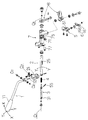
本発明の実施の形態について、図1ないし図5を基に説明する。本実施の形態に関するものの、その構成は、図1に示す如く、一方の端部側にノブ部11を有するものであって、後記シフトピース2の一部に形成される取付点(O2 )を支点にして一定の方向であるXX方向に揺動運動をするとともに、上記ノブ部11が設けられる側とは反対の側に形成される先端部12を支点にして上記XX方向に対して直交するYY方向に上記XX方向への揺動運動よりも大きな円弧角を有するように揺動運動をするシフトレバー1と、当該シフトレバー1の上記先端部12にピンジョイント結合されるものであって上記シフトレバー1のXX方向への揺動運動に応じてその軸線方向に直線運動をするロッド3と、当該ロッド3を支持するように当該ロッド3の周りに同心円状に設けられるものであって上記シフトレバー1のYY方向への揺動運動に応じて上記ロッド3の軸線を中心にしてロッド3とともに回転運動をするように形成されたシフトピース2と、当該シフトピース2及び上記ロッド3を保持するものであって上記シフトレバー1のXX方向及びYY方向への揺動運動反力を受け止めるハウジング7と、当該ハウジング7のところに、上記YY方向に扇形に展開するように設けられるものであって上記ロッド3の軸線(O1O1)に対して直角に設けられたディテントピン55が係合するディテントブロック5と、上記ロッド3に設けられたディテントピン55を上記ディテントブロック5側へ常時押し付けるように、上記ロッド3の軸線(O1O1)方向に所定の押圧力を与えるスプリング4と、からなることを基本とするものである。
【0009】
このような基本構成からなるものにおいて、上記シフトピース2は、基本的には円筒状の形態からなるものであり、その一方の端部には円筒部の軸線に直交するようにクレビス状のブラケット(クレビスブラケット)21が設けられるようになっている。そして、このクレビスブラケット21の先端部のところに上記シフトレバー1の取付点(O2)が形成され、この取付点(O2)を支点にして上記シフトレバー1はXX方向に揺動をするようになっているものである。また、このクレビスブラケット21を介して、本シフトピース2は、上記シフトレバー1のYY方向への揺動運動に応じて、上記ロッド3の軸線(O1O1)を中心にしてロッド3とともに回転運動をするようになっているものである。そして更に、このようなシフトピース2の円筒部のところには、軸線(O1O1)方向に平行なように所定の長さを有する開口穴からなるスリット25が設けられるようになっており、後に述べるディテントピン55が、このスリット25内を上記軸線(O1O1)方向に摺動運動するようになっているものである。
【0010】
このような円筒状のシフトピース2内には、所定の長さを有するロッド3が挿入されるようになっているものである。そして、このようなロッド3の一端側には上記シフトレバー1の先端部12に形成された球面部が連結され、ピンジョイント結合構造からなる連結部31が形成されるようになっているものである。また、このピンジョイント結合構造からなる連結部31は、上記シフトレバー1のYY方向への揺動運動の支点(O1)を形成するようになっているものである。従って、このようなロッド3の軸線(O1O1)は、シフトレバー1のYY方向への揺動運動の支点を成すとともに、当該YY方向への揺動運動に伴なう上記シフトピース2の回転運動の中心軸をも成すようになっているものである。そして、このようなロッド3の一部には、本ロッド3の軸線(O1O1)に直交するようにディテントピン55が取付けられるようになっている。そして、このディテントピン55は、上記シフトピース2に設けられた長穴状のスリット25内に設置され、当該スリット25内を、その軸線(O1O1)方向に摺動運動するようになっているものである。
【0011】
なお、このディテントピン55は、上記シフトレバー1のYY方向への揺動運動及び上記シフトピース2の回転運動に伴なって、上記シフトピース2及びロッド3とともにYY方向への回転運動をするようになっているものである。また、このようなディテントピン55が一体的に取付けられるロッド3の一方の端部であって上記シフトレバー1の先端部12との間においてピンジョイント結合される側(連結部31)でない方の端部のところには、本ロッド3を、その軸線(O1O1)方向であって本ロッド3を上記ピンジョイント結合部側へ押付けるように作動するスプリング4が設けられるようになっているものである。
【0012】
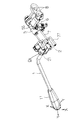
そして、このようなシフトピース2及びロッド3は、基本的には円筒状の形態からなるハウジング7内に収容されるようになっているものである。このハウジング7は、上記シフトレバー1のXX方向並びにYY方向への揺動運動の反力を受け止める役目を果すとともに、本ハウジング7の一端側に設けられた取付部77を介して、本シフト装置全体をステアリングコラム等に取付ける取付ブラケットの役目をも果すようになっているものである。そして、このような機能を果すハウジング7の一部には、図1及び図2に示す如く、開口部75が設けられるようになっており、この開口部75を介して上記ディテントピン55が外部に突出するようになっているものである。また、この開口部75の際には、フランジ71が設けられており、このフランジ71のところに、P、R、N、D、L等からなる所定のシフト位置を規制するディテントブロック5が取付けられるようになっているものである。そして、このように取付けられたディテントブロック5の各ディテント部(P,R,N,D,L)51のところに、上記開口部75のところから突出するように設けられたディテントピン55が係合するとともに、当該ディテントピン55は上記スプリング4のばね反力によって、上記ディテントブロック5の各ディテント部51側へ押付けられるようになっているものである。
【0013】
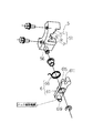
このようなディテントブロック5のところには、図1及び図3に示すようなロック機構6が設けられるようになっている。このロック機構6は、図3に示す如く、上記ディテントブロック5のところに設けられた軸部56の周りに相対回転運動が可能なように取付けられるレバー61と、当該レバー61の先端部に形成されたU字状溝611側を、常時、上記ディテント部51側に押付けるように作動するスプリング66と、からなることを基本とするものである。そして、上記レバー61の一端619側は別途設けられたロック解除機構に連結され、当該ロック解除機構の作動により、上記レバー61の先端部に形成されたU字状溝611をPロック(パーキングロック)状態から解放させるようになっているものである。
【0014】
そして、もう一方側の端部には上記U字状溝611が設けられるようになっており、上記ディテントピン55がディテント部51の一つであるP位置に係合したときに、上記ディテントピン55が上記U字状溝611内に係合して(図4参照)、ディテントピン55のこの位置(P位置)からの離脱を抑止するようにしているものである。すなわち、Pロック(パーキングロック)を形成するようになっているものである。また、このようなU字状溝611の隣には先端部が平面状に形成されたストッパ部615が設けられるようになっており、このストッパ部615を形成する平面部のところが、上記ディテントピン55がディテント部51のR位置に係合したときに、この状態から上記ディテントピン55が不意にP位置へ移動するのを抑止するようにしているものである。すなわち、図5に示す如く、R位置保持(R位置ホールド)が形成されるようになっているものである。
【0015】
また、このような構成からなる上記シフトピース2の一端側であって上記クレビスブラケット21の設けられる側とは反対側のところには、図1及び図2に示す如く、伝達レバー8が設けられるようになっている。この伝達レバー8は、上記シフトレバー1のYY方向への揺動運動に伴なう上記シフトピース2の上記ロッド3の軸線(O1O1)を中心とした回転運動に応じて作動するものであって、これら一連の作動に伴なう上記ディテントピン55の各ディテント部51への係合状態(位置)を変速機側へ伝達する役目を担っているものである。
【0016】
このような構成からなる本実施の形態のものについての、その作動態様、特に、変速シフト操作について説明する。まず。操作者(ドライバー)は、図2において、シフトレバー1のノブ部11を持って(握って)、本シフトレバー1をXX方向へ、この方向に働くスプリング4のばね反力に抗した状態で操作する。これによって、ディテントブロック5におけるP、R、N、D、L等の所定の位置に係合していたディテントピン55は、上記ロッド3の軸線(O1O1)方向への移動に連動して上記シフトピース2に設けられたスリット25内を摺動運動して、ディテントブロック5のディテント部51との係合状態から解放される。そして、このような状態において、上記シフトレバー1のノブ部11をYY方向に移動させる。そうすると、上記シフトレバー1のYY方向への揺動運動に伴なってシフトピース2が上記ロッド3の軸線(O1O1)を中心にして当該ロッド3と共に回転運動をし、当該ロッド3に一体的に設けられたディテントピン55がYY方向に移動する。そして、この位置にてノブ部11から力を抜くと、本シフトレバー1は、ロッド3を介して、その先端部12に働いているばね反力の作用により、その軸線(O1O1)方向における最初の状態に戻される。その結果、ディテントピン55がディテントブロック5のディテント部51と係合するようになる。これによって、上記ディテントピン55のディテントブロック5に形成された所定の係合位置(P,R,N,D,L)への係合が完了することとなる。そして更に、このような一連の作動に応じて、上記シフトレバー1のYY方向への揺動運動に伴なう伝達レバー8の作動によって、上記ディテントブロック5におけるP、R、N、D、L等の所定の位置への変速シフト操作が変速機へと伝達されることとなる。
【0017】
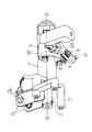
このような一連のシフト作動において、本実施の形態のものにおいては、特に、次のP位置へのシフト時、あるいはR位置へのシフト時において、ロック機構6の作動により、各シフト作動の確実性が確保されるようになっている。まず、図4に示す如く、ディテントピン55がディテント部51の一つであるP位置に係合したときには、上記ディテントピン55がロック機構6を形成するレバー61の先端部に形成されたU字状溝611内に係合して、ディテントピン55のこの位置(P位置)からの離脱が抑止されるようになる。すなわち、Pロック(パーキングロック)が形成されることとなる。また、上記レバー61の一方の先端部には、U字状溝611の隣に平面状に形成されたストッパ部615が設けられており、このストッパ部615を形成する先端の平面部のところが、図5に示す如く、上記ディテントピン55がディテント部51のR位置に来たときに、当該ディテントピン55と接触するようになる。これによって、ディテントピン55のR位置からP位置への移動を抑止するようにしている。すなわち、R位置保持(R位置ホールド)が形成される。その結果、R位置からP位置へ不意にシフトされるのを抑止し、シフト操作の安全性が確保されるようになる。
【0018】
【発明の効果】
本発明によれば、自動変速機に用いられる変速操作用シフト装置に関して、一方の端部側にノブ部を有するものであって、後記シフトピースの一部に形成される取付点を支点にして一定の方向であるXX方向に揺動運動をするとともに、上記ノブ部が設けられる側とは反対の側に形成される先端部を支点にして上記XX方向に対して直交するYY方向に上記XX方向への揺動運動よりも大きな円弧角を有するように揺動運動をするシフトレバーと、当該シフトレバーの上記先端部にピンジョイント結合されるものであって上記シフトレバーのXX方向への揺動運動に応じてその軸線方向に直線運動をするロッドと、当該ロッドを支持するように当該ロッドの周りに同心円状に設けられるものであって上記シフトレバーのYY方向への揺動運動に応じて上記ロッドの軸線を中心にして回転運動をするように形成されたシフトピースと、当該シフトピース及び上記ロッドを保持するものであって上記シフトレバーの上記XX方向及びYY方向への揺動運動反力を受け止めるハウジングと、当該ハウジングに、上記YY方向に扇形に展開するように設けられるものであって上記ロッドの軸線に対して直角に設けられたディテントピンが係合するディテントブロックと、上記ロッドに設けられたディテントピンを上記ディテントブロック側へ常時押し付けるように、上記ロッドの軸線方向に所定の押圧力を与えるスプリングと、からなるようにした構成を採ることとしたので、ディテントピンのディテント部に対する係合及び解除作動を、ロッドの軸線方向への移動にて形成させるようにするとともに、ディテントピンのディテント部におけるP、R、N、D、L各部へのシフト作動を上記ロッドの軸線を中心としたシフトピースの回転運動にて形成させることができるようになり、シフトレバーのXX方向並びにYY方向への作動が円滑に行なわれるようになった。その結果、本シフト装置全体におけるシフト操作フィーリングの向上を図ることができるようになった。
【0019】
また、本発明においては、上記シフトピースを円筒状の形態からなるようにするとともに、その一部にロッドの軸線方向に平行にスリットを設け、このスリット内を上記ロッドの軸線に対して直角に設けられたディテントピンがロッドの軸線方向に摺動運動をするようにした構成を採ることとしたので、上記ディテントピンとディテントブロックとの間における入力荷重が単純な押付圧力のみとなり、上記ディテントブロック周りの構造を小形化することができるようになった。その結果、上記シフトレバーの揺動運動角度(円弧角)を小さく設定することができるようになり、本シフト装置全体の小形化及び軽量化を図ることができるようになった。
【0020】
また、本発明においては、上記ハウジングまたはディテントブロックのところに、上記ディテントピンが上記ディテントブロックの特定の位置であるPの位置に係合したときに、上記ディテントピンが、この係合位置から離脱しないように規制をするロック機構を設けるようにした構成を採ることとしたので、シフト操作におけるP位置ロックあるいはR位置ホールドが確実に行なわれるようになり、シフト操作における安全性の向上を図ることができるようになった。
【図面の簡単な説明】
【図1】本発明の全体構成を示す展開斜視図である。
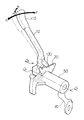
【図2】本発明の全体構成を示す斜視図である。
【図3】本発明の主要部を成すディテントブロック及びロック機構周りの構成を示す展開斜視図である。
【図4】本発明にかかるロック機構がPロック状態にある場合を示す斜視図である。
【図5】本発明にかかるロック機構がRホールド状態にある場合を示す斜視図である。
【図6】従来例の全体構成を示す斜視図である。
【符号の説明】
1 シフトレバー
11 ノブ部
12 先端部
2 シフトピース
21 クレビスブラケット
25 スリット
3 ロッド
31 連結部
4 スプリング
5 ディテントブロック
51 ディテント部
55 ディテントピン
56 軸部
6 ロック機構
61 レバー
611 U字状溝
615 ストッパ部
619 一端
66 スプリング
7 ハウジング
71 フランジ
75 開口部
77 取付部
8 伝達レバー[0001]
BACKGROUND OF THE INVENTION
The present invention relates to a shift device for a shift operation used in an automatic transmission, and in particular, allows a shift operation to be performed in XY2 directions orthogonal to each other of a shift lever and specifies a shift position. The present invention relates to a shift device for an automatic transmission which is configured to be performed by a detent plate (detent block) having a predetermined form.
[0002]
[Prior art]
A conventional shift operation shift device used in an automatic transmission includes, for example, a
[0003]
[Problems to be solved by the invention]
By the way, in the above-described conventional device, when a gear shifting operation is to be performed, first, the
[0004]
[Means for Solving the Problems]
In order to solve the above problems, the following measures are taken in the present invention. That is, according to the first aspect of the present invention, a shift operation shift device used in an automatic transmission has a knob portion on one end side, and is formed on a part of a shift piece described later. Oscillates in the XX direction, which is a fixed direction, with the point as a fulcrum, and is orthogonal to the XX direction with the tip formed on the side opposite to the side where the knob is provided as a fulcrum. A shift lever that oscillates so as to have a larger arc angle in the YY direction than the oscillating motion in the XX direction, and a pin joint coupled to the tip portion of the shift lever. A rod that linearly moves in the axial direction in response to a swinging motion in the XX direction, and a concentric circle that is provided around the rod so as to support the rod. A shift piece formed to rotate about the axis of the rod in response to a swinging movement of the rod in the YY direction, and holds the shift piece and the rod. A housing for receiving a reaction force of swinging motion in the XX direction and the YY direction, and a detent provided in the housing so as to expand in a fan shape in the YY direction and provided at right angles to the axis of the rod A shift for an automatic transmission comprising: a detent block with which a pin is engaged; and a spring that applies a predetermined pressing force in the axial direction of the rod so as to constantly press the detent pin provided on the rod toward the detent block. In the device, the shift piece has a cylindrical shape, and a part of the axial direction of the rod A detent pin provided in a direction perpendicular to the axis of the rod slides in the slit, and the detent pin is located at the detent block. When the detent pin is engaged with a predetermined position of the block, the detent pin is regulated so as not to be detached from the engagement position, and is relatively rotated around a shaft portion provided at the detent block. A lock mechanism comprising a lever that is mounted so that it can move, and a spring that operates to constantly press the U-shaped groove formed at the tip of the lever against the detent section provided in the detent block. It was decided to adopt a configuration in which the
[0005]
By adopting such a configuration, in the present invention, the engagement and release operation of the detent pin with respect to the detent portion is formed by movement in the axial direction of the rod, and the detent portion of the detent pin Since the shift operation to each of P, R, N, D, and L is formed by the rotational movement of the shift piece around the axis of the rod, the shift lever can be operated in the XX direction and the YY direction. As a result, the shift operation feeling in the entire shift apparatus can be improved.
[0006]
Further, in the present invention, the shift piece is formed in a cylindrical shape, and a slit is provided in a part of the shift piece in parallel to the axial direction of the rod, and the inside of the slit is relative to the axial line of the rod. A configuration was adopted in which detent pins provided at right angles were slid in the axial direction of the rod. By adopting such a configuration, in those of the present invention, it is possible to improve the shift operation feeling. Further, since the input load between the detent pin and the detent block is only a simple pressing pressure, the structure around the detent block can be reduced in size, and the entire shift device can be reduced in weight. Will be able to.
[0007]
Further, in the present invention , when the detent pin is engaged with the position of P which is a specific position of the detent block at the detent block, the detent pin is detached from the engagement position. In order to prevent this, a configuration is adopted in which a lock mechanism is provided to regulate. By adopting such a configuration, the P position lock in the shift operation, that is, the parking lock is surely performed in the present invention. Accordingly, it is possible to improve safety in the shift operation.
[0008]
DETAILED DESCRIPTION OF THE INVENTION
An embodiment of the present invention will be described with reference to FIGS. As shown in FIG. 1, the present embodiment has a
[0009]
In such a basic configuration, the
[0010]
A
[0011]
The
[0012]
The
[0013]
A
[0014]
The
[0015]
Further, as shown in FIGS. 1 and 2, a transmission lever 8 is provided on one end side of the
[0016]
The operation mode of the embodiment having such a configuration, particularly, a shift shift operation will be described. First. In FIG. 2, the operator (driver) holds (holds) the
[0017]
In such a series of shift operations, in the present embodiment, each shift operation is reliably performed by the operation of the
[0018]
【The invention's effect】
According to the present invention, a shift operation shift device used in an automatic transmission has a knob portion on one end side, and has a mounting point formed on a part of a shift piece described later as a fulcrum. It swings in the XX direction, which is a certain direction, and the XX in the YY direction perpendicular to the XX direction with the tip formed on the side opposite to the side where the knob is provided as a fulcrum. A shift lever that oscillates so as to have a larger arc angle than the oscillating motion in the direction, and a pin joint coupled to the tip of the shift lever, and the swaying of the shift lever in the XX direction A rod that linearly moves in the axial direction in accordance with a dynamic motion, and a concentric circle around the rod so as to support the rod, and a swinging motion of the shift lever in the YY direction Accordingly, a shift piece formed to rotate about the axis of the rod and the shift piece and the rod are held, and the shift lever swings in the XX and YY directions. A housing that receives the reaction force, and a detent block that is provided in the housing so as to expand in a fan shape in the YY direction and engages with a detent pin that is provided at right angles to the axis of the rod; Since the detent pin provided on the rod is configured to include a spring that applies a predetermined pressing force in the axial direction of the rod so as to constantly press the detent pin on the detent block side, Engagement and release operation with respect to the detent part is formed by movement of the rod in the axial direction. At the same time, the shift operation to the P, R, N, D, and L portions in the detent portion of the detent pin can be formed by the rotational movement of the shift piece around the axis of the rod. The operation in the XX direction and the YY direction can be performed smoothly. As a result, the shift operation feeling in the entire shift apparatus can be improved.
[0019]
In the present invention, the shift piece is formed in a cylindrical shape, and a slit is provided in a part thereof in parallel to the axial direction of the rod, and the inside of the slit is perpendicular to the axial line of the rod. Since the detent pin provided is configured to slide in the axial direction of the rod, the input load between the detent pin and the detent block is only a simple pressing pressure, and the area around the detent block The structure of can now be miniaturized. As a result, the swinging movement angle (arc angle) of the shift lever can be set small, and the entire shift device can be reduced in size and weight.
[0020]
Further, in the present invention, when the detent pin is engaged with the position P of the detent block at the housing or the detent block, the detent pin is detached from the engagement position. Since the lock mechanism for restricting the movement is provided, the P position lock or the R position hold in the shift operation is surely performed, and the safety in the shift operation is improved. Can now.
[Brief description of the drawings]
FIG. 1 is an exploded perspective view showing an overall configuration of the present invention.
FIG. 2 is a perspective view showing the overall configuration of the present invention.
FIG. 3 is a developed perspective view showing a configuration around a detent block and a lock mechanism constituting the main part of the present invention.
FIG. 4 is a perspective view showing a case where the lock mechanism according to the present invention is in a P-lock state.
FIG. 5 is a perspective view showing a case where the locking mechanism according to the present invention is in an R-hold state.
FIG. 6 is a perspective view showing an overall configuration of a conventional example.
[Explanation of symbols]
DESCRIPTION OF SYMBOLS 1
Claims (1)
Priority Applications (1)
| Application Number | Priority Date | Filing Date | Title |
|---|---|---|---|
| JP2001128774A JP4792166B2 (en) | 2001-04-26 | 2001-04-26 | Shift device for automatic transmission |
Applications Claiming Priority (1)
| Application Number | Priority Date | Filing Date | Title |
|---|---|---|---|
| JP2001128774A JP4792166B2 (en) | 2001-04-26 | 2001-04-26 | Shift device for automatic transmission |
Publications (2)
| Publication Number | Publication Date |
|---|---|
| JP2002321543A JP2002321543A (en) | 2002-11-05 |
| JP4792166B2 true JP4792166B2 (en) | 2011-10-12 |
Family
ID=18977422
Family Applications (1)
| Application Number | Title | Priority Date | Filing Date |
|---|---|---|---|
| JP2001128774A Expired - Fee Related JP4792166B2 (en) | 2001-04-26 | 2001-04-26 | Shift device for automatic transmission |
Country Status (1)
| Country | Link |
|---|---|
| JP (1) | JP4792166B2 (en) |
Family Cites Families (5)
| Publication number | Priority date | Publication date | Assignee | Title |
|---|---|---|---|---|
| JPH0617622Y2 (en) * | 1987-12-15 | 1994-05-11 | 三菱自動車工業株式会社 | Automatic transmission shift lock device |
| JPH02108618U (en) * | 1989-02-17 | 1990-08-29 | ||
| JPH07251647A (en) * | 1994-03-16 | 1995-10-03 | Nippon Cable Syst Inc | Column shift device for automatic transmission |
| JPH0999752A (en) * | 1995-10-05 | 1997-04-15 | Delta Kogyo Co Ltd | Column type change device |
| JP2000038102A (en) * | 1998-07-22 | 2000-02-08 | Fuji Heavy Ind Ltd | Knee guard for vehicle speed change operation device |
-
2001
- 2001-04-26 JP JP2001128774A patent/JP4792166B2/en not_active Expired - Fee Related
Also Published As
| Publication number | Publication date |
|---|---|
| JP2002321543A (en) | 2002-11-05 |
Similar Documents
| Publication | Publication Date | Title |
|---|---|---|
| US10253878B2 (en) | Device for locking an operating element of an automatic transmission of a vehicle, method for operating such a device and switching device for switching an automatic transmission of a vehicle | |
| JP4103178B2 (en) | Reclining device | |
| JP6371382B2 (en) | Device for displacing an operating element of an automatic transmission of a vehicle to a parking position, a method for operating such a device and a shift device for shifting an automatic transmission of a vehicle | |
| US5520425A (en) | Power closing door latch device for motor vehicle | |
| WO2010032552A1 (en) | Door opening and closing device for vehicle | |
| JP4642419B2 (en) | Shift lever lock device for automatic transmission for vehicle | |
| JP3920599B2 (en) | Manual input device | |
| US6194676B1 (en) | Turn signal switch device | |
| KR100462114B1 (en) | Crossbar locking device of roof rack | |
| JP4792166B2 (en) | Shift device for automatic transmission | |
| CN104203031B (en) | With the safety belt lock unlocking interlock | |
| US7637180B2 (en) | Parking brake apparatus | |
| JP3793484B2 (en) | Locking device for adjustable steering column | |
| JP2008105584A (en) | Shift lever device | |
| JP3588676B2 (en) | Shift lever device for automatic transmission | |
| US6725739B2 (en) | Rotary tilt mechanism | |
| JP7359442B2 (en) | shift lever device | |
| JP2008007096A (en) | Steering device | |
| US6662604B1 (en) | Anti-theft means for vehicle | |
| JPH09290657A (en) | Shift lever device | |
| JP2000038047A (en) | Shift lever device | |
| JP2002337566A (en) | Shift device for automatic transmission | |
| JPH1122822A (en) | Shifting device for a sequentially operated transmission | |
| JP5714237B2 (en) | Cylinder lock | |
| JPH0635839Y2 (en) | Parking brake operating device |
Legal Events
| Date | Code | Title | Description |
|---|---|---|---|
| A621 | Written request for application examination |
Free format text: JAPANESE INTERMEDIATE CODE: A621 Effective date: 20080409 |
|
| A977 | Report on retrieval |
Free format text: JAPANESE INTERMEDIATE CODE: A971007 Effective date: 20101213 |
|
| A131 | Notification of reasons for refusal |
Free format text: JAPANESE INTERMEDIATE CODE: A131 Effective date: 20101217 |
|
| A521 | Written amendment |
Free format text: JAPANESE INTERMEDIATE CODE: A523 Effective date: 20110214 |
|
| TRDD | Decision of grant or rejection written | ||
| A01 | Written decision to grant a patent or to grant a registration (utility model) |
Free format text: JAPANESE INTERMEDIATE CODE: A01 Effective date: 20110704 |
|
| A01 | Written decision to grant a patent or to grant a registration (utility model) |
Free format text: JAPANESE INTERMEDIATE CODE: A01 |
|
| A61 | First payment of annual fees (during grant procedure) |
Free format text: JAPANESE INTERMEDIATE CODE: A61 Effective date: 20110725 |
|
| FPAY | Renewal fee payment (event date is renewal date of database) |
Free format text: PAYMENT UNTIL: 20140729 Year of fee payment: 3 |
|
| R150 | Certificate of patent or registration of utility model |
Free format text: JAPANESE INTERMEDIATE CODE: R150 |
|
| LAPS | Cancellation because of no payment of annual fees |