JP4792153B2 - Fastening structure of high-strength yarn of nyroll frame - Google Patents
Fastening structure of high-strength yarn of nyroll frame Download PDFInfo
- Publication number
- JP4792153B2 JP4792153B2 JP2000050963A JP2000050963A JP4792153B2 JP 4792153 B2 JP4792153 B2 JP 4792153B2 JP 2000050963 A JP2000050963 A JP 2000050963A JP 2000050963 A JP2000050963 A JP 2000050963A JP 4792153 B2 JP4792153 B2 JP 4792153B2
- Authority
- JP
- Japan
- Prior art keywords
- lens
- knot
- yarn
- tip
- water
- Prior art date
- Legal status (The legal status is an assumption and is not a legal conclusion. Google has not performed a legal analysis and makes no representation as to the accuracy of the status listed.)
- Expired - Fee Related
Links
Images


Classifications
-
- G—PHYSICS
- G02—OPTICS
- G02C—SPECTACLES; SUNGLASSES OR GOGGLES INSOFAR AS THEY HAVE THE SAME FEATURES AS SPECTACLES; CONTACT LENSES
- G02C1/00—Assemblies of lenses with bridges or browbars
- G02C1/04—Bridge or browbar secured to or integral with partial rims, e.g. with partially-flexible rim for holding lens
Landscapes
- Physics & Mathematics (AREA)
- Health & Medical Sciences (AREA)
- General Physics & Mathematics (AREA)
- Ophthalmology & Optometry (AREA)
- Optics & Photonics (AREA)
- Eyeglasses (AREA)
Description
【0001】
【発明の属する技術分野】
本発明は水糸等の高張力糸を用いてレンズを保持するナイロールフレーム、特に高張力糸の止着構造に関するものである。
【0002】
【従来の技術】
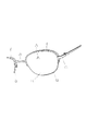
ナイロールフレームとはレンズを保持する為にリムの一部を分断して水糸等の高張力糸が使用されているメガネフレームである。ハーフリムとすることによりメガネフレームは軽量化され、視界を広げることが出来る。図9は従来から多用されている基本的なナイロールフレームを表しているが、概略長方形断面をした円弧状のハーフリム(イ)の両端に水糸(ロ)の先端を止着し、ハーフリム(イ)と水糸(ロ)によってレンズ(ハ)が保持される。そして両ハーフリム(イ)、(イ)はブリッジ(ニ)にて連結され、リム外側にはヨロイ(ホ)、(ホ)が取付けられていて、ツルはこのヨロイ(ホ)に蝶番を介して折畳み出来るように連結されている。
【0003】
図10は図9のA―A断面拡大図を示しているが、ハーフリム(イ)の内周及びレンズ(ハ)の外周には溝が形成され、この両溝には断面がダルマ形をしたクッション性のある繋ぎ材(ヘ)が嵌っている。すなわち、該繋ぎ材(ヘ)にてハーフリム(イ)とレンズ(ハ)が繋がれ、レンズ(ハ)はハーフリム(イ)から外れないようになっている。
【0004】
図11は水糸(ロ)の止着構造を示している。ハーフリム端には2個の穴を貫通して設け、この両穴に水糸端が挿通して止着されるが、該穴の大きさは0.7mmで両穴間距離は1.5mmと成っている。この状態で両端が止着されている水糸(ロ)にレンズ(ハ)を嵌めるならば、水糸(ロ)には約1〜3kgの張力が作用し、その結果、水糸(ロ)は図11(b)に示すように溝(ト)に嵌りこむ。そして水糸(ロ)は両穴から抜け出すことはないが、穴の角(チ)に食い込んで切断するケースが多い。
【0005】
図12(a)は前記図9のA―A断面拡大図の別形態であり、(b)はこの場合のハーフリム(イ)の端部を示している。このハーフリムはT型リムと称して繋ぎ材(ヘ)を必要とせず、内周には凸部(リ)を沿設し、この凸部(リ)はレンズ溝に嵌っている。そしてハーフリム端には同じく2個の穴(ヌ)、(ヌ)が所定の間隔をおいて設けられ、この2個の穴(ヌ)、(ヌ)に水糸が挿通されて止着される。従って水糸に張力が作用するならば、同じく穴(ヌ)の角に食い込んで切断する。
【0006】
図13はレンズの外周に形成した溝に嵌ることが出来る細いワイヤーで構成したハーフリムであって、(a)はレンズ溝に嵌っている断面を示し、(b)はハーフリムの端部を示している。ハーフリムはレンズ溝に落とし込まれる為にスリムな外観となるが、先端には止着片(ル)がロウ付けされ、この止着片(ル)に2個の穴(ヌ)、(ヌ)が設けられている。水糸はこの2個の穴(ヌ)、(ヌ)に挿通されて止着される為に、張力が作用するならば切断することは前記従来例と同じである。
【0007】
ナイロールフレームに使用される一般的な水糸はその太さが0,52mmであって、引張り強度は約10kgある。しかし、従来のナイロールフレームにおける水糸の止着構造では約3,6kgで切断してしまい、水糸本来の引張り強度が生かされていない。
【0008】
一方、図14は水糸端にリング(オ)を形成し、このリング(オ)をハーフリム端に設けているカギ(ワ)に係止した止着構造も知られている。この止着構造に関しては出願人が平成9年8月25日付けで特許出願を行っていて(特願平9−250091号)、(b)に拡大図を示すようにリング(オ)が内面に凹凸を有すパイプ(カ)にてカシメられるならば、約8.4kgの引っ張り強度が得られる。しかし、この水糸(ロ)の両端はパイプ(カ)が嵌められてカシメられる為に図15に示すように長さLは定まってしまう。
【0009】
特に、小売店で視力に合ったレンズ外形を加工する際、小さくなれば水糸(ロ)の張力が足らなくなってレンズが外れ易くなり、逆にレンズ周長が大きくなればリング(オ)がカギ(ワ)に掛からなくなってしまう。また無理してカギ(ワ)に掛けるならばレンズ(ハ)並びに水糸(ロ)に大きな負担がかかってレンズ(ハ)の割れや水糸(ロ)の破断が発生する。
【0010】
【発明が解決しようとする課題】
このようにナイロールフレームの高張力糸の止着構造には上記のごとき問題がある。本発明が解決しようとする課題はこの問題点であり、高張力糸の引っ張り強度が高く、又レンズの周長に適した長さに簡単に調整することが出来るナイロールフレームの高張力糸の止着構造を提供する。
【0011】
【課題を解決する為の手段】
ナイロールフレームとしての基本形態は従来と同じであり、ブリッジで連結される両ハーフリムとハーフリムの先端に両端が止着される高調力糸で構成され、レンズはハーフリムに片側の約半分が拘束されると共に、反対側には高張力糸が張設されてレンズを保持している。勿論、ナイロールフレームとしての構造はこの基本形態に限定せず、ハーフリムの先端に高張力糸を直接止着する場合に限らず、ツル端に止着することもあり、又別部材を介在して高張力糸を止着することもある。
【0012】
ところで、本発明に係る高張力糸の止着構造はカギに結んで止着する構造である。しかし単に先端部に結び目を作っただけでは抜けてしまう為に先端に玉を形成する。又玉を作ることなく2重結びをすることで抜けないようにすることもある。一方、フレーム側には上記カギではなく穴を形成し、該穴から抜けないように高張力糸先端には結び目を作る。以下、本発明に係る実施例を図面に基づいて詳細に説明する。
【0013】
【実施例】
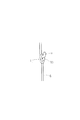
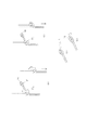
図1は本発明のナイロールフレームの一部を示している実施例である。両ハーフリム1,1はブリッジ2と共に連続した1本の線材にて成形され、該ハーフリム1に嵌ったレンズ3は水糸4にて保持されている。同図の5は補助ブリッジを表わし、概略門型をした補助ブリッジ5はハーフリム1,1とブリッジ2との間に形成されている凹部に引っ掛けられて取付けられている。そして6はツルを示し、ツル端にはコイルバネ7が形成されていて、上記水糸4の先端は補助ブリッジ5の脚8とコイルバネ7とに止着されてレンズ3を保持している。
【0014】
このフレームではハーフリム1,1とブリッジ2が連続した細い1本の線材からなっているが、補強ブリッジ5を取付けることでブリッジ部の強度は高くなる。又、ツル端に形成したコイルバネ7はハーフリム外側に起立した軸に嵌って取付けられて開閉することが出来る。そして、ツル6は開いた状態からコイルバネ7を捩り変形することで僅かに押し開く機能を備えている。
【0015】
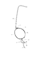
図2はナイロールフレームにおける水糸4の止着構造を示している実施例であってコイルバネ先端の拡大図を示している。水糸4はコイルバネ先端に形成されているカギ9に結ばれて止着されるが、単に結んだだけでは解けてしまう為に水糸端には玉10を作っている。この玉10は加熱することで端部は液状化し、表面張力で自然に丸くなり、水糸4に大きな張力が作用しても結び目11が解けることはない。
【0016】
この場合の引っ張り強度は約7kgとなり、前記図11に示している従来の止着構造に比較して約2倍の引っ張り強度が得られる。そして、結び目11の位置を変えることでレンズ3の周長が変化しても簡単に対応することが可能である。図3(a)〜(d)は図2の結び方を示しているが、(a)は水糸4の先端部をカギ9に結んで先端を適当な長さでカットする。(b)は先端をライターなどで加熱して丸く固める。(c)は水糸4に張力を加えるならば、丸くなった先端の玉10は結び目11に引き寄せられ、玉10は結び目11に係止する。(d)は結び目11を基点としてレンズの大きさを考慮して水糸4の長さLを定め、先端を丸く固めて玉10を作る。この水糸先端部は同じように別のカギに結び付けられる。
【0017】
図4は本発明の止着構造を示す他の実施例を示している。この止着構造の場合もコイルバネ7の先端に設けたカギ9に水糸4を結んで止着しているが、2重結びが行われている。一重結びでは結び目11が解けてしまうが、同図のように2重結びを行うことで解けることはなく、引っ張り強度は約10.8kgとなり、水糸自体の引っ張り強度がそのまま得られる。
【0018】
図5は上記2重結びをする場合の結び方を示している。(a)はカギ9に結んで1番目の結び目11aを適当な位置に作り、(b)では結び目11aの上に2番目の結び目11bを作っている。1番目の結び目11aはレンズ3の大きさを考慮して適当な位置に設けられ、さらに2番目の結び目11bを作ることで解けないようにしているが、水糸先端は結び目11bから延びている為に適当な位置で切断して(c)のようにする。
【0019】
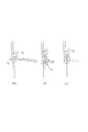
図6は本発明に係る高張力糸の止着構造を示すさらに別の実施例である。コイルバネ7の先端には穴を設け、この穴を通過することが出来ない大きさの結び目12を形成して該穴に係止する方法である。(a)はU型のカギ13aを形成し、このカギ13aに結び目12を先端に作って水糸4を係止している場合である。又(b)はカギ13bがリング型としていて、水糸先端に結んだ結び目12はカギ13bの穴から抜けないように係止している。そしてこれらの結び目12にも先端に玉14を作って該結び目12が解けないようにしている。この玉14は同図の(c)、(d)に示すように、結び目12から延びている水糸4を適度な長さに切断し、残された部分を加熱して適度な大きさの玉14を作ることが出来る。
【0020】
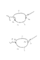
ところで、ナイロールフレームの形態は図1に示す場合に限定するものではなく、図7(a)、(b)に示しているナイロールフレームとすることも出来る。(a)のナイロールフレームはハーフリム15の両端にカギ16a,16bを形成し、これらのカギ16a,16bに水糸4の先端を結んで止着している。一方の(b)に示すナイロールフレームは1本の線材を曲げ成形してハーフリム17,17、ブリッジ18、それにヨロイ19,19を連続して形成している。そしてハーフリム17とブリッジ18の境界凹部20a、ハーフリム17とヨロイ19の境界凹部20bに水糸4の先端を結んで止着している。
【0021】
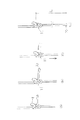
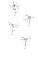
図8は高張力糸の止着構造を示している別形態である。ハーフリム21の外側には軸受けと成るパイプ22がロウ付けされ、一方のツル端にはツバ23を有す軸24をロウ付け固定している。そしてパイプ22の上面にはカム25が、又ツバ23の下面にもカム26がそれぞれ設けられている。(a)は軸24がパイプ22から分離している場合であり、水糸4はパイプ穴27を通り、軸24の中心に貫通している穴を挿通して先端には結び目28を有している。
【0022】
上記結び目28は水糸4に張力が作用しても軸の中心穴から抜けない大きさであると共に解けないようになっていて、1つには前記図6(d)に示しているように玉14を形成する場合、又は2重結びとする場合がある。そして軸24はパイプ穴27に嵌って回転することが出来てツル6は開閉する。(b)はツルが折畳まれた場合、(c)はツル6が開いている場合を示している。さらに(d)は開いたツル6を外方向へ押し開いている場合であるが、水糸4には張力が作用していて、パイプ穴27に嵌っている軸24を引っ張り、カム25、26はツバ23の下面及びパイプ上面に当接し、ツル6の開閉に伴って摺動する。
【0023】
そして(d)に示すように、ツル6が開いた状態からさらに外方向へ押し開く場合には、両カム25,26が互いに噛み合って軸24は上方へ移動する。その結果水糸4に作用する張力は大きくなり、軸24を押し下げる力が反力として作用し、その結果、ツル6が閉じる方向に押圧力として発生する。すなわち、従来のバネ蝶番と同じ機能を呈し得る。このように、水糸4はレンズを保持するものであるが、ハーフリムの端に直接止着する場合に限らず、フレームを構成するツル端に止着することもある。
【0024】
以上述べたように、本発明のナイロールフレームにおける高張力糸の止着構造は、高張力糸先端に結び目を作って係止したものであり、次のような効果を得ることが出来る。
【0025】
【発明の効果】
本発明のナイロールフレームは水糸端に結び目を形成し、これを係止することでレンズを保持することが出来る。したがって水糸が角に食い込んで破断するようなことはなく、レンズを安定して保持出来る。例えば結び目が解けないように先端に玉を作っている場合の引っ張り張力は約7kg,又2重結びの場合には約10.8kgの引っ張り張力が得られる。そして結びによって高張力糸先端を止着する為に、レンズの周長が如何様であってもレンズに合わせて止着することが出来、最も適した張力にてレンズの保持が可能となる。
【図面の簡単な説明】
【図1】ナイロールフレームを示す実施例。
【図2】本発明の高張力糸の止着構造。
【図3】図2に示す結び目の結び方。
【図4】本発明の高張力糸の止着構造であって2重結びを示す。
【図5】図4に示す2重結びの結び方。
【図6】本発明の高張力糸の他の止着構造。
【図7】ナイロールフレームの具体例。
【図8】本発明の高張力糸の別の止着構造。
【図9】従来の止着構造を備えたナイロールフレーム。
【図10】図9のA―A断面拡大図。
【図11】従来の高張力糸の止着構造。
【図12】 (a)はハーフリムとレンズの関係、(b)はハーフリムの先端部。
【図13】 (a)はハーフリムとレンズの関係、(b)はハーフリムの先端部。
【図14】水糸端にリングを形成した止着構造。
【図15】両端にリングを形成した水糸。
【符号の説明】
1 ハーフリム
2 ブリッジ
3 レンズ
4 水糸
5 補助ブリッジ
6 ツル
7 コイルバネ
8 脚
9 カギ
10 玉
11 結び目
12 結び目
13 カギ
14 玉
15 ハーフリム
16 カギ
17 ハーフリム
18 ブリッジ
19 ヨロイ
20 凹部
21 ハーフリム
22 パイプ
23 ツバ
24 軸
25 カム
26 カム
27 パイプ穴
28 結び目[0001]
BACKGROUND OF THE INVENTION
The present invention relates to a nip roll frame that holds a lens using a high-strength yarn such as water yarn, and more particularly to a fastening structure for a high-tensile yarn.
[0002]
[Prior art]
A nyroll frame is a spectacle frame in which a high-strength yarn such as water yarn is used by dividing a part of a rim to hold a lens. By using a half rim, the glasses frame is lightened and the field of view can be expanded. FIG. 9 shows a basic nyroll frame that has been widely used in the past. The ends of a water thread (b) are fixed to both ends of an arc-shaped half rim (A) having a substantially rectangular cross section, and the half rim (I ) And the water thread (b) hold the lens (c). And both half rims (A), (I) are connected by a bridge (D), and Yoroi (E), (E) are attached to the outside of the rim, and the crane is attached to this Yoroi (E) via a hinge. It is connected so that it can be folded.
[0003]
FIG. 10 shows an enlarged cross-sectional view taken along the line AA in FIG. 9. Grooves are formed on the inner periphery of the half rim (A) and the outer periphery of the lens (C). Cushioning connecting material (f) is fitted. That is, the half rim (A) and the lens (C) are connected by the connecting material (F) so that the lens (C) is not detached from the half rim (A).
[0004]
FIG. 11 shows the fastening structure of the water yarn (b). The half rim end is provided with two holes penetrating through it, and the water thread ends are inserted through these holes and fixed, but the size of the hole is 0.7 mm and the distance between the holes is 1.5 mm. It is made up. In this state, if the lens (C) is fitted to the water thread (B) that is fixed at both ends, a tension of about 1 to 3 kg is applied to the water thread (B). As a result, the water thread (B) Is fitted into the groove (g) as shown in FIG. The water thread (b) does not slip out of both holes, but often cuts into the corners of the holes.
[0005]
FIG. 12A is another form of the AA cross-sectional enlarged view of FIG. 9, and FIG. 12B shows the end portion of the half rim (A) in this case. This half rim is called a T-shaped rim, does not require a connecting material (f), has a convex portion (re) along the inner periphery, and this convex portion (re) fits into the lens groove. Similarly, two holes (nu) and (nu) are provided at predetermined intervals at the end of the half rim, and a water thread is inserted into these two holes (nu) and (nu) to be fastened. . Therefore, if tension acts on the water thread, it will also cut into the corner of the hole.
[0006]
FIG. 13 shows a half rim composed of a thin wire that can be fitted in a groove formed on the outer periphery of the lens. (A) shows a cross section fitted in the lens groove, and (b) shows an end of the half rim. Yes. Since the half rim is dropped into the lens groove, it has a slim appearance, but a fastening piece (le) is brazed to the tip, and two holes (nu) and (nu) are attached to this fastening piece (le). Is provided. Since the water thread is inserted through these two holes (nu) and (nu) and fixed, the cutting is performed in the same manner as in the conventional example when the tension is applied.
[0007]
A typical water yarn used for a nyroll frame has a thickness of 0.52 mm and a tensile strength of about 10 kg. However, in the conventional water yarn fixing structure in the nyroll frame, the water yarn is cut at about 3.6 kg, and the original tensile strength of the water yarn is not utilized.
[0008]
On the other hand, FIG. 14 shows a fastening structure in which a ring (e) is formed at the end of the water thread, and this ring (e) is locked to a key (wa) provided at the end of the half rim. Regarding this fastening structure, the applicant filed a patent application on August 25, 1997 (Japanese Patent Application No. 9-250091), and as shown in the enlarged view in (b), the ring (e) is on the inner surface. A tensile strength of about 8.4 kg can be obtained if it is caulked with a pipe (figure) having irregularities on the surface. However, the length L of the both ends of the water thread (b) is fixed as shown in FIG.
[0009]
In particular, when processing a lens outer shape that suits the eyesight at a retail store, if it becomes smaller, the tension of the water thread (b) will become insufficient, and the lens will easily come off, and conversely if the lens circumference increases, the ring (e) will It won't hang on the key. Moreover, if it is forcibly applied to the key, the lens (c) and the water thread (b) will be subjected to a heavy load, and the lens (c) will break and the water thread (b) will break.
[0010]
[Problems to be solved by the invention]
As described above, the fixing structure of the high tension yarn of the nyroll frame has the above-mentioned problems. The problem to be solved by the present invention is this problem. The tensile strength of the high-tensile yarn is high, and the high-strength yarn of the nyroll frame can be easily adjusted to a length suitable for the circumference of the lens. Provides wearing structure.
[0011]
[Means for solving the problems]
The basic form as a nyroll frame is the same as the conventional one, and it is composed of both half rims connected by a bridge and a high-strength yarn with both ends fastened to the tip of the half rim, and the lens is restrained about half on one side by the half rim. At the same time, a high tension yarn is stretched on the opposite side to hold the lens. Of course, the structure of the nyroll frame is not limited to this basic form, and is not limited to the case where the high-tensile yarn is directly fixed to the tip of the half rim. High tension yarns may be fastened.
[0012]
By the way, the fixing structure of the high-tensile yarn according to the present invention is a structure in which the high-tension thread is fixed by being tied to a key. However, a ball is formed at the tip because the knot is simply made at the tip. In some cases, double knots are made without making balls to prevent them from falling out. On the other hand, a hole is formed on the frame side instead of the above key, and a knot is formed at the tip of the high tension yarn so as not to come out of the hole. Hereinafter, embodiments according to the present invention will be described in detail with reference to the drawings.
[0013]
【Example】
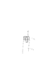
FIG. 1 is an embodiment showing a part of a nyroll frame of the present invention. Both
[0014]
In this frame, the half rims 1, 1 and the bridge 2 are made of a single thin wire, but the strength of the bridge portion is increased by attaching the reinforcing bridge 5. The
[0015]
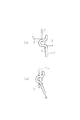
FIG. 2 shows an enlarged view of the tip end of the coil spring, which is an embodiment showing the fastening structure of the
[0016]
In this case, the tensile strength is about 7 kg, and a tensile strength about twice that of the conventional fastening structure shown in FIG. 11 can be obtained. Then, by changing the position of the
[0017]
FIG. 4 shows another embodiment showing the fastening structure of the present invention. In the case of this fastening structure, the
[0018]
FIG. 5 shows how to tie the double tie. (a) is tied to the key 9 to make the
[0019]
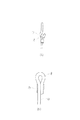
FIG. 6 shows still another embodiment of the high-tension yarn fastening structure according to the present invention. In this method, a hole is provided at the tip of the
[0020]
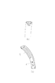
By the way, the form of the nyroll frame is not limited to the case shown in FIG. 1, and the nyroll frame shown in FIGS. 7A and 7B can also be used. In the (a) nyroll frame,
[0021]
FIG. 8 shows another embodiment showing the fastening structure of the high tension yarn. A
[0022]
The knot 28 has such a size that it cannot be pulled out from the center hole of the shaft even when tension is applied to the
[0023]
As shown in (d), when the
[0024]
As described above, the high-strength yarn fastening structure in the nyroll frame according to the present invention is formed by locking a knot at the tip of the high-tensile yarn, and the following effects can be obtained.
[0025]
【The invention's effect】
The nyroll frame of the present invention can hold the lens by forming a knot at the end of the water thread and locking it. Therefore, the water thread does not break into the corner and break, and the lens can be stably held. For example, when a ball is made at the tip so that the knot is not broken, a tensile tension of about 7 kg is obtained, and when a double knot is used, a tensile tension of about 10.8 kg is obtained. Since the tip of the high tension yarn is fixed by knotting, the lens can be fixed according to the lens regardless of the circumference of the lens, and the lens can be held with the most suitable tension.
[Brief description of the drawings]
FIG. 1 shows an example of a nyroll frame.
FIG. 2 is a fastening structure of a high-tensile yarn according to the present invention.
FIG. 3 shows how to tie the knot shown in FIG.
FIG. 4 shows a fastening structure of a high-tensile yarn according to the present invention and shows a double knot.
5 is a double knot shown in FIG.
FIG. 6 shows another fastening structure of the high tension yarn of the present invention.
FIG. 7 is a specific example of a nyroll frame.
FIG. 8 shows another fastening structure of the high-tensile yarn of the present invention.
FIG. 9 is a nyroll frame having a conventional fastening structure.
10 is an AA cross-sectional enlarged view of FIG.
FIG. 11 shows a conventional high tension yarn fastening structure.
12A is a relationship between a half rim and a lens, and FIG. 12B is a front end portion of the half rim.
13A is a relationship between a half rim and a lens, and FIG. 13B is a front end portion of the half rim.
FIG. 14 is a fastening structure in which a ring is formed at the end of a water thread.
FIG. 15 shows a water thread in which rings are formed at both ends.
[Explanation of symbols]
1 Half rim 2 Bridge 3
10 balls
11 Knot
12 Knot
13 keys
14 balls
15 Half rim
16 keys
17 Half rim
18 bridge
19 Yoroi
20 Recess
21 half rim
22 Pipe
23 brim
24 axes
25 cams
26 cam
27 Pipe hole
28 Knot
Claims (1)
Priority Applications (2)
| Application Number | Priority Date | Filing Date | Title |
|---|---|---|---|
| JP2000050963A JP4792153B2 (en) | 2000-02-28 | 2000-02-28 | Fastening structure of high-strength yarn of nyroll frame |
| US09/793,649 US6315407B2 (en) | 2000-02-28 | 2001-02-27 | High-tension thread fastening structure for eyeglasses frame |
Applications Claiming Priority (1)
| Application Number | Priority Date | Filing Date | Title |
|---|---|---|---|
| JP2000050963A JP4792153B2 (en) | 2000-02-28 | 2000-02-28 | Fastening structure of high-strength yarn of nyroll frame |
Publications (2)
| Publication Number | Publication Date |
|---|---|
| JP2001242422A JP2001242422A (en) | 2001-09-07 |
| JP4792153B2 true JP4792153B2 (en) | 2011-10-12 |
Family
ID=18572683
Family Applications (1)
| Application Number | Title | Priority Date | Filing Date |
|---|---|---|---|
| JP2000050963A Expired - Fee Related JP4792153B2 (en) | 2000-02-28 | 2000-02-28 | Fastening structure of high-strength yarn of nyroll frame |
Country Status (2)
| Country | Link |
|---|---|
| US (1) | US6315407B2 (en) |
| JP (1) | JP4792153B2 (en) |
Families Citing this family (4)
| Publication number | Priority date | Publication date | Assignee | Title |
|---|---|---|---|---|
| DE102009005633A1 (en) | 2009-01-21 | 2010-07-29 | Markus Temming | eyeglass frame |
| US9134549B2 (en) | 2013-03-13 | 2015-09-15 | William Stevenson | Methods and structure for affixing frames elements to eyeglass lenses |
| DE102014113046A1 (en) * | 2014-09-10 | 2016-03-10 | Temming Holding Gmbh | Glasses and mounting method of a spectacle lens |
| DE102019203035B3 (en) * | 2019-03-06 | 2020-08-27 | ViSi Management GmbH | glasses |
Family Cites Families (9)
| Publication number | Priority date | Publication date | Assignee | Title |
|---|---|---|---|---|
| JPS55135814A (en) * | 1979-04-12 | 1980-10-23 | Seiko Epson Corp | Wire material fixing structure for lens holding |
| JPS6142331U (en) * | 1984-08-24 | 1986-03-18 | 三菱自動車工業株式会社 | Fully floating rigid axle with freewheel hub |
| JPS6145576U (en) * | 1984-08-27 | 1986-03-26 | 東洋シャッター株式会社 | Rotating fittings |
| JPH07301772A (en) * | 1994-05-09 | 1995-11-14 | Kenzo Okuda | Spectacles and their temples |
| JP3184070B2 (en) * | 1995-08-29 | 2001-07-09 | ダイワ精工株式会社 | Fine wire having resin ball and method for producing the same |
| FR2742886B1 (en) * | 1995-12-22 | 1998-01-23 | Perie Jean Claude | DEVICE FOR FIXING LENSES ON A GLASSES FRAME |
| JPH1066491A (en) * | 1996-08-28 | 1998-03-10 | Toshiyuki Suematsu | Device for fishing |
| TW390442U (en) * | 1997-07-28 | 2000-05-11 | Opcom Inc | Eyeglass frame having metal-and-string rims |
| JPH1172752A (en) * | 1997-08-29 | 1999-03-16 | Isao Heii | Semi-rimless frame |
-
2000
- 2000-02-28 JP JP2000050963A patent/JP4792153B2/en not_active Expired - Fee Related
-
2001
- 2001-02-27 US US09/793,649 patent/US6315407B2/en not_active Expired - Lifetime
Also Published As
| Publication number | Publication date |
|---|---|
| JP2001242422A (en) | 2001-09-07 |
| US20010017686A1 (en) | 2001-08-30 |
| US6315407B2 (en) | 2001-11-13 |
Similar Documents
| Publication | Publication Date | Title |
|---|---|---|
| US6606769B1 (en) | Carabiner for use with strap | |
| KR100766673B1 (en) | Binding band and binding band set | |
| EP0712986B1 (en) | Non-cuttable device for attachment of shoplifting detection tag | |
| JP4792153B2 (en) | Fastening structure of high-strength yarn of nyroll frame | |
| US4559676A (en) | Filament fastener with locking head | |
| US20040050124A1 (en) | Key ring | |
| WO1981000839A1 (en) | Engagement lock | |
| JP3170262U (en) | Safety belt | |
| JP2017523897A (en) | Shoe strapping system and shoes manufactured with this strapping system | |
| US20060005575A1 (en) | Article of jewelry which encircles a body part without a clasp | |
| US6575798B2 (en) | Device for attaching a flexible linear element to an inflatable tube of an inflatable craft | |
| EP3753443A1 (en) | Method and tool for preventing sliding down of shoulder belt, shoulder belt, and bag | |
| US8108974B2 (en) | Closure for joining at least two pieces of material | |
| KR102153730B1 (en) | Wire lock and manufacturing method of the wire for the same that | |
| US5457504A (en) | Eyeglass frame | |
| JP2001194631A (en) | Nylol (r) frame | |
| JPS6346741Y2 (en) | ||
| US2194697A (en) | Shipping tag | |
| JP6878348B2 (en) | Web for catching tools and catching tools | |
| KR200277857Y1 (en) | A scarf attached with the knotted ribbon | |
| JP7084027B2 (en) | Nyroll type glasses | |
| JP2000098304A (en) | Spectacles | |
| JP2001078806A (en) | Length adjuster with loosening stopper for suspension belt | |
| JP3442936B2 (en) | Ball net and its manufacturing method | |
| KR200234596Y1 (en) | A Strap for Belt |
Legal Events
| Date | Code | Title | Description |
|---|---|---|---|
| A621 | Written request for application examination |
Free format text: JAPANESE INTERMEDIATE CODE: A621 Effective date: 20061222 |
|
| A131 | Notification of reasons for refusal |
Free format text: JAPANESE INTERMEDIATE CODE: A131 Effective date: 20090825 |
|
| A521 | Written amendment |
Free format text: JAPANESE INTERMEDIATE CODE: A523 Effective date: 20091026 |
|
| A131 | Notification of reasons for refusal |
Free format text: JAPANESE INTERMEDIATE CODE: A131 Effective date: 20100511 |
|
| A02 | Decision of refusal |
Free format text: JAPANESE INTERMEDIATE CODE: A02 Effective date: 20101130 |
|
| A521 | Written amendment |
Free format text: JAPANESE INTERMEDIATE CODE: A523 Effective date: 20110228 |
|
| A911 | Transfer to examiner for re-examination before appeal (zenchi) |
Free format text: JAPANESE INTERMEDIATE CODE: A911 Effective date: 20110328 |
|
| TRDD | Decision of grant or rejection written | ||
| A01 | Written decision to grant a patent or to grant a registration (utility model) |
Free format text: JAPANESE INTERMEDIATE CODE: A01 Effective date: 20110621 |
|
| A01 | Written decision to grant a patent or to grant a registration (utility model) |
Free format text: JAPANESE INTERMEDIATE CODE: A01 |
|
| A61 | First payment of annual fees (during grant procedure) |
Free format text: JAPANESE INTERMEDIATE CODE: A61 Effective date: 20110725 |
|
| FPAY | Renewal fee payment (event date is renewal date of database) |
Free format text: PAYMENT UNTIL: 20140729 Year of fee payment: 3 |
|
| R150 | Certificate of patent or registration of utility model |
Free format text: JAPANESE INTERMEDIATE CODE: R150 |
|
| R250 | Receipt of annual fees |
Free format text: JAPANESE INTERMEDIATE CODE: R250 |
|
| R250 | Receipt of annual fees |
Free format text: JAPANESE INTERMEDIATE CODE: R250 |
|
| LAPS | Cancellation because of no payment of annual fees |