JP4792122B2 - Data center - Google Patents
Data center Download PDFInfo
- Publication number
- JP4792122B2 JP4792122B2 JP2010213026A JP2010213026A JP4792122B2 JP 4792122 B2 JP4792122 B2 JP 4792122B2 JP 2010213026 A JP2010213026 A JP 2010213026A JP 2010213026 A JP2010213026 A JP 2010213026A JP 4792122 B2 JP4792122 B2 JP 4792122B2
- Authority
- JP
- Japan
- Prior art keywords
- air
- rack
- hot zone
- temperature
- fan
- Prior art date
- Legal status (The legal status is an assumption and is not a legal conclusion. Google has not performed a legal analysis and makes no representation as to the accuracy of the status listed.)
- Active
Links
Images


Classifications
-
- Y—GENERAL TAGGING OF NEW TECHNOLOGICAL DEVELOPMENTS; GENERAL TAGGING OF CROSS-SECTIONAL TECHNOLOGIES SPANNING OVER SEVERAL SECTIONS OF THE IPC; TECHNICAL SUBJECTS COVERED BY FORMER USPC CROSS-REFERENCE ART COLLECTIONS [XRACs] AND DIGESTS
- Y02—TECHNOLOGIES OR APPLICATIONS FOR MITIGATION OR ADAPTATION AGAINST CLIMATE CHANGE
- Y02D—CLIMATE CHANGE MITIGATION TECHNOLOGIES IN INFORMATION AND COMMUNICATION TECHNOLOGIES [ICT], I.E. INFORMATION AND COMMUNICATION TECHNOLOGIES AIMING AT THE REDUCTION OF THEIR OWN ENERGY USE
- Y02D10/00—Energy efficient computing, e.g. low power processors, power management or thermal management
Landscapes
- Air Conditioning Control Device (AREA)
Description
本発明は、ラック内に収容されたサーバなどの電子機器で発生する熱を効率よく除去するデータセンタに関するものである。 The present invention relates to a data center that efficiently removes heat generated in an electronic device such as a server housed in a rack.
サーバなどの電子機器は、一般的に、ラック内に高密度に多段に収容されて空調室内に配置される。電子機器では電力消費に伴い熱が発生するので、この熱による悪影響を排除するために、空調機などの冷却システムによりラック内に収容された電子機器に空調空気(冷風)を供給し、電子機器で発生した熱を除去するのが一般的である。 Electronic devices such as servers are generally housed in a rack in a multi-stage and arranged in an air conditioned room. In electronic equipment, heat is generated with power consumption. In order to eliminate the adverse effects of this heat, conditioned air (cold air) is supplied to the electronic equipment contained in the rack by a cooling system such as an air conditioner. It is common to remove the heat generated in.
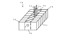
従来のデータセンタとして、図7に示すように、空調室内に、サーバなどの電子機器を収容したラック71を複数台左右方向に並べてラック列72を形成すると共に、このラック列72の背面同士を間隔をおいて向かい合わせて床面上に配置し、その向かい合わせたラック列72の左右方向、即ち、長手方向の端部側に、ラック列72の間を塞ぐように扉75及び屋根パネル74を設けることで、背面同士が向き合ったラック列72の背面側の間に空調室内と仕切ってホットゾーンを区画した、所謂、モジュラー型データセンタ70を空調室内に単数若しくは複数設置し、全体としてデータセンタを構成したものがある(例えば、特許文献1参照)。なお、この扉75は、ホットゾーンの中に入るためのものである。
As a conventional data center, as shown in FIG. 7, a rack row 72 is formed by arranging a plurality of racks 71 containing electronic devices such as servers in the air-conditioning room in the left-right direction, and the back surfaces of the rack rows 72 are connected to each other. The doors 75 and the roof panels 74 are arranged on the floor faced to be spaced apart from each other, and closed in the left-right direction of the rack rows 72 facing each other, that is, at the end portions in the longitudinal direction. By installing a single or a plurality of so-called
また、空調室内にモジュラー型データセンタ70を設置するタイプのデータセンタである特許文献1では、ラック71のうち1つが冷却機器(空調機)を内蔵しており、ホットゾーン内の空気を冷却してラック71の前面側に排気するようにしている。つまり、モジュラー型データセンタ70では、ラック71の前面から空調空気(冷風)を導入して、ラック71内の電子機器で発生した熱を除去すると共に、熱を吸収した空気をラック71の背面からホットゾーンに排気し、このホットゾーン内の空気を冷却機器で冷却してラック71の前面側に排気している。
In
ラック71内に収容された冷却機器には、水やフロンガスなどの冷媒を供給するための冷媒供給・戻りパイプ76が接続される。ラック71内の各電子機器には、電力供給ライン77を介して電力が供給される。 A refrigerant supply / return pipe 76 for supplying a refrigerant such as water or chlorofluorocarbon gas is connected to the cooling device accommodated in the rack 71. Electric power is supplied to each electronic device in the rack 71 via a power supply line 77.
このように、特定の場所(ホットゾーン)に電子機器で発生した熱を集中させることにより、冷却機器を効率良く作動させることが可能となる。すなわち、冷却機器には一般的な空調設備同等に低温な冷媒を供給する必要がなくなるため、安価に、かつ、除湿をすることなく空調空気(冷風)を効率よく作り出すことが可能となる。 Thus, by concentrating the heat generated by the electronic device in a specific place (hot zone), the cooling device can be operated efficiently. That is, since it is not necessary to supply a low-temperature refrigerant to the cooling device as in a general air conditioning facility, it is possible to efficiently produce conditioned air (cold air) at low cost and without dehumidification.
しかしながら、上述のデータセンタでは、ラック71(ラック列72)の上面や屋根パネル74の上面から空調室内に電子機器で発生した熱が放出されてしまい、該熱と、冷却機器によって生成したラック71の前面側から送風する空調空気(冷風)とが混合することがあり、該混合の結果、ラック71の前面から導入する空調空気(冷風)の温度が十分に冷やせなくなる場合には、これをモジュラー型データセンタ70に組み込まれた冷却機器とは別の空調機(室内エアコン)で更に事前冷却する必要があった。これでは、空調機(室内エアコン)での消費エネルギーが無駄であり、省エネの観点から問題があった。
However, in the above-described data center, heat generated in the electronic device is released from the upper surface of the rack 71 (rack row 72) and the upper surface of the roof panel 74 into the air-conditioned room, and the rack 71 generated by the heat and the cooling device. If the temperature of the conditioned air (cold air) introduced from the front of the rack 71 cannot be sufficiently cooled as a result of the mixing, the conditioned air (cold air) blown from the front side of the rack may be mixed. It was necessary to further pre-cool with an air conditioner (indoor air conditioner) separate from the cooling device incorporated in the
なお、サーバには上方に排気を行うタイプのものもあるため、このようなサーバをラック71内に収容する場合には、ラック71上面から空調室内に放出される熱が多く前記の問題が顕著に現れる。 In addition, since there is a type of server that exhausts upwards, when such a server is accommodated in the rack 71, a large amount of heat is released from the upper surface of the rack 71 into the air-conditioning room, and the above problem is remarkable. Appear in
そこで、本発明の目的は、上記課題を解決し、ラック内の電子機器で発生する熱を効率よく除去して、空調機での消費エネルギーの低減を図ることが可能なデータセンタを提供することにある。 SUMMARY OF THE INVENTION Accordingly, an object of the present invention is to provide a data center that can solve the above-described problems and efficiently remove heat generated by electronic devices in a rack to reduce energy consumption in an air conditioner. It is in.
本発明は上記目的を達成するために創案されたものであり、少なくとも、空調室と、該空調室の床面上にサーバなどの電子機器を多段に収容するラックを複数台左右方向に並べ形成されたラック列と、前記ラック内に収容された電子機器で発生する熱を除去すべく前記空調室内を空調する空調機とを備えたデータセンタにおいて、前記空調機は、前記ラック列が配置される前記空調室とは別の部屋あるいは屋外に設けられており、前記ラック列の背面同士を間隔をおいて向かい合わせて前記空調室内の床面上に配置し、その向かい合わせたラック列の左右方向の端部側に、ラック列の下縁から前記空調室の天井に延びるパネルを設けると共に、両ラック列の前縁上部に天井に延びるパーティションを設けて、前記空調室内にホットゾーンを区画し、そのホットゾーン上の前記空調室の天井に該ホットゾーン内の比重が小さくなった空気を上方に吸引して排気する複数の排気口を前記ラック列に対して平面視で対向するように左右方向に並べ形成すると共に、前記空調室内の前記ホットゾーンの外部であって前記ラック列の前方の天井に前記空調機からの前記比重より大きい比重の空調空気を鉛直下方に吹き出す複数の吹出口を前記ラック列のそれぞれに対して平面視で対向するように左右方向に並べ形成し、前記空調機と前記複数の排気口とを接続する排気ダクトを前記空調室の天井裏であって前記ラック列に対して平面視で対向するように設けると共に、前記空調機と前記複数の吹出口とを接続する吹出ダクトを前記空調室の天井裏であって前記ラック列に対して平面視で対向するように設け、前記排気ダクト及び前記吹出ダクトのそれぞれは、前記ラック列に対して平面視で対向している部分は、平面視で直線状であり且つ互いに間隔をおいて配置され、前記吹出ダクトを介して前記複数の吹出口から前記空調室へ鉛直下方に吹き出した空調空気を前記ラック列の前面から背面に通して前記ホットゾーンに導入した後、前記ホットゾーンの空気を前記複数の排気口から前記排気ダクトを介して前記空調機に導入して前記空調空気の流動性を高めることを特徴とするデータセンタである。 The present invention was devised to achieve the above object, and at least a plurality of racks that accommodate multiple stages of electronic devices such as servers on the floor surface of the air conditioning room and the air conditioning room are arranged in the left-right direction. In the data center, the rack is arranged in the data center, and the air conditioner is configured to air-condition the interior of the air-conditioning room so as to remove heat generated by the electronic equipment accommodated in the rack. It is provided in a room separate from the air conditioning room or outdoors , and the rack rows are arranged on the floor surface of the air conditioning room with the back surfaces of the rack rows facing each other with a space therebetween. A panel extending from the lower edge of the rack row to the ceiling of the air conditioning room is provided on the end side in the direction, and a partition extending to the ceiling is provided above the front edge of both rack rows to partition the hot zone in the air conditioning room. And, so as to face in a plan view a plurality of exhaust ports for exhausting by suction the specific gravity of the air conditioning chamber the hot zone to the ceiling on the hot zone is smaller air upwardly to the rack row A plurality of outlets that are arranged side by side in the left-right direction and that blow out vertically conditioned air having a specific gravity greater than the specific gravity from the air conditioner to the ceiling in front of the rack row outside the hot zone in the air conditioning room Are arranged in the left-right direction so as to face each of the rack rows in a plan view, and an exhaust duct connecting the air conditioner and the plurality of exhaust ports is provided on the back of the ceiling of the air-conditioning room and the rack. The air duct and the plurality of air outlets are provided so as to face the row in plan view, and are opposed to the rack row in the plan view on the ceiling of the air conditioning chamber. Each of the exhaust duct and the blowout duct is opposed to the rack row in a plan view and is linear in the plan view and arranged at a distance from each other. Air conditioned air blown vertically downward from the plurality of outlets to the air conditioning chamber through the front through the rear of the rack row is introduced into the hot zone, and then the air in the hot zone is supplied to the plurality of exhaust ports. The data center is introduced to the air conditioner through the exhaust duct to improve the fluidity of the conditioned air .
前記ファンには、前記ホットゾーンから吸引される空気の温度を所定温度範囲、または所定温度に保つように前記ファンの回転数を制御する回転数制御装置を設けてもよい。 The fan may be provided with a rotational speed control device that controls the rotational speed of the fan so as to keep the temperature of the air sucked from the hot zone within a predetermined temperature range or a predetermined temperature.
前記排気ダクトと前記吹出ダクトにそれぞれ温度センサを設けて構成され、前記ファンには、前記各温度センサが計測する温度差に基づいて、前記空調室と前記ホットゾーン間の温度差を目標とする値に一致させるように、前記ファンの回転数を制御する回転数制御装置を設けてもよい。 The exhaust duct and the outlet duct are each provided with a temperature sensor, and the fan is targeted for the temperature difference between the air-conditioned room and the hot zone based on the temperature difference measured by each temperature sensor. You may provide the rotation speed control apparatus which controls the rotation speed of the said fan so that it may correspond with a value.
本発明によれば、ラック内の電子機器で発生する熱を効率よく除去して、空調機での消費エネルギーの低減を図ることができる。 ADVANTAGE OF THE INVENTION According to this invention, the heat which generate | occur | produces with the electronic device in a rack can be removed efficiently, and the reduction of the energy consumption in an air conditioner can be aimed at.
以下、本発明の好適な実施の形態を添付図面にしたがって説明する。 Preferred embodiments of the present invention will be described below with reference to the accompanying drawings.
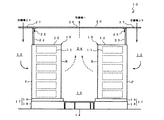
図1は、本実施形態に係るデータセンタの概略断面図であり、図2はその平面図、図3はその側面図、図4はその正面図である。 1 is a schematic sectional view of a data center according to the present embodiment, FIG. 2 is a plan view thereof, FIG. 3 is a side view thereof, and FIG. 4 is a front view thereof.
図1〜4に示すように、データセンタ10は、少なくとも、天井、床面、及び4つの側壁で形成された箱状の空調室13と、サーバなどの電子機器11を多段に収容する複数台のラック12を左右方向に並べ形成されたラック列15と、ラック12内に収容された電子機器11で発生する熱を除去すべく空調室13内を空調する空調機(図示せず)とを備える。
As shown in FIGS. 1 to 4, the
ラック12内には、サーバや、CPU、ネットワーク機器、ストレージデバイスのような情報通信技術の設備機器である電子機器11が多段に収容される。
In the
データセンタ10では、空調室13の床面14上にラック12を複数台(本実施形態では12台)左右方向に並べてラック列15を形成すると共に、そのラック列15の背面R同士を間隔をおいて向かい合わせて配置している。ラック列15を間隔をおいて配置することで、ラック列15間には作業通路16が形成される。
In the
これらラック列15は、床面14上に免震装置17を介して配置される。本実施形態では、免震装置17として、架台18上にベアリングを介して免震台19を設けたものを用いたが、これに限定されるものではない。
These
ラック列15の左右には、ラック列15の下縁から天井20に延びるパネル21が設けられる。このパネル21には、作業通路16に出入するための扉22が設けられる。パネル21は、免震装置17上に設けられる。
各ラック列15の前縁上部には、天井20に延びるパーティション23が設けられる。パーティション23およびパネル21の上端は、天井20に対して移動可能に設けられる。
A
パネル21とパーティション23の上端には、ホットゾーン24と空調室13とをシールするための天井シール部材25が設けられる。本実施形態では、天井シール部材25としてゴムシートを用い、そのゴムシートをパーティション23のホットゾーン24側の上端に、その上端部がホットゾーン24側に湾曲するようにボルトなどで固定した。
A ceiling seal member 25 for sealing the
これにより、両ラック列15、パーティション23、およびパネル21で空調室13と仕切られたホットゾーン24が区画形成される。
As a result, a
ホットゾーン24内の天井20には、ホットゾーン24内の熱を排気する排気口26が少なくとも1つ(図2では3つ)形成される。この排気口26は排気ダクト53(図2参照)を介して空調機の吸込口に接続される。排気ダクト53には、ホットゾーン24から吸引する空気の温度を測定するための排気側温度センサ69b(図5参照)が設けられる。
The
ホットゾーン24以外の空調室13の天井20(図1ではラック列15の前方の天井20)には、空調機からの空調空気(冷風)を鉛直下方に吹き出す吹出口27が少なくとも1つ(図2では3つ)形成される。この吹出口27は、吹出ダクト52(図2参照)を介して空調機の吹出口と接続される。吹出ダクト52には、吹出口27から吹き出す空調空気の温度を測定するための吹出側温度センサ69a(図5参照)が設けられる。
On the
図5に示すように、空調機51は、ホットゾーン24内の空気を吸引するファン54と、ファン54の下流側に設けられ、ファン54からの空気を冷却して空調空気を吹き出す冷却コイル(DC;DryCoil)55とを備える。
As shown in FIG. 5, the
また、本実施形態に係るデータセンタ10は、排気口26から排気された空気の熱を空調機51の冷却コイル55で冷却する前に回収する熱回収手段56を備える。
In addition, the
熱回収手段56は、排気口26から排気された空気から熱を回収する熱回収コイル(HC;HeatCaptureCoil)57と、熱回収コイル57に熱媒体を供給する熱媒体供給管58と、熱回収コイル57で熱回収した熱媒体をボイラなど他の設備に排出する熱媒体排出管59と、熱媒体供給管58に設けられた熱媒体用ポンプ60と、熱媒体用ポンプ60の下流側の熱媒体供給管58に設けられたレギュレータ61と、熱媒体排出管59中の熱媒体の温度を測定する熱媒体用温度センサ62と、熱媒体用温度センサ62の測定温度(熱媒体の温度)が最も高くなるように、レギュレータ61の開度を調整して熱媒体の流量を制御する熱回収用制御装置63aとを備える。熱回収用制御装置63aはPLC(ProgrammableLogicController)からなる。
The heat recovery means 56 includes a heat recovery coil (HC; HeatCaptureCoil) 57 that recovers heat from the air exhausted from the
本実施形態では、熱媒体として水を用いた。熱回収コイル57に供給する水の温度は、例えば、20℃程度であり、熱回収コイル57通過後の温水の温度は、例えば、35〜40℃程度である。
In this embodiment, water is used as the heat medium. The temperature of the water supplied to the
熱回収コイル57は、空調機51と一体に設けられ、ファン54の下流側かつ冷却コイル55の上流側に設けられる。これにより、排気口26から排気された空気の熱のみならず、ファン54で発生した熱も熱回収コイル57で回収することが可能となる。熱回収コイル57で熱回収された空気は、冷却コイル55で冷却されて所定温度(例えば、23℃程度)の空調空気となる。
The
冷却コイル55には、冷媒を供給するための冷媒供給管64、および冷媒を戻すための冷媒戻り管65が接続される。冷媒供給管64には冷媒用ポンプ66が設けられる。冷媒は、例えば水である。
Connected to the cooling
冷媒供給管64および冷媒戻り管65には、冷媒を冷却コイル55に通さずにバイパスするためのバイパス管67が接続され、バイパス管67と冷媒戻り管65の接続箇所には、冷媒のバイパス/非バイパスの混合比率を調節できる三方弁68が設けられる。この三方弁68は(一般にモーター付きの)電磁弁であり、冷却コイル55を通過した後の空調空気の温度が所定温度(設定温度)となるように、冷却コイル55を通過する冷媒流量の制御がなされる。
A bypass pipe 67 for bypassing the refrigerant without passing through the cooling
冷却用制御装置63bは、吹出ダクト52に設けられた吹出側温度センサ69aで測定した空調空気の温度が所定温度よりも高い場合には、三方弁68で冷媒を冷却コイル55により多く流すようにし、吹出側温度センサ69aで測定した空調空気の温度が所定温度よりも低い場合には、三方弁68で冷媒をバイパス側により多く流し冷却コイル55を通過させないようにする。
The cooling
あるいは、このバイパス管67がない場合、すなわち二方弁によって冷媒の流量の制御を行うことも可能であり、その方式でも吹出側温度センサ69aで測定した空調空気の温度を所定温度に合わせるように冷却コイル55への冷媒の通過流量を決めるべく、バルブの開度が自動で制御される。
Alternatively, when the bypass pipe 67 is not provided, that is, the flow rate of the refrigerant can be controlled by a two-way valve. Even in this method, the temperature of the conditioned air measured by the outlet
このように、冷却用制御装置63bで冷却コイル55に流れる冷媒の流量を制御することにより、所望の温度の空調空気が得られる。冷却用制御装置63bはPLCからなる。
In this way, by controlling the flow rate of the refrigerant flowing through the cooling
ファン54には、出力周波数可変の動力INV(inverter)盤63dが接続される。ファン54は、動力INV盤63dの出力周波数に応じた回転数で回転する。この動力INV盤63dには、排気口26から排気された空気の温度を所定温度範囲、または所定温度(例えば、40〜42℃)に保つように、動力INV盤63dに出力周波数を出力してファン54の回転数を制御する回転数制御装置63cが接続される。
The
回転数制御装置63cは、予め設定された最高閾値とする温度Thigh(例えば、42℃)と最低閾値とする温度Tlow(例えば、40℃)に基づき、排気ダクト53に設けられた排気側温度センサ69bで測定した温度(排気口26から排気された空気の温度)tが最高閾値とする温度Thighよりも高い場合には、ファン54の回転数を一定値ずつ上げる(例えば、動力INV盤63dの出力周波数を1分間に2Hzずつ上げる。また、その上げる動作は、時間間隔をとりつつ行う場合もある)。また、排気側温度センサ69bで測定した温度tが最低閾値とする温度Tlowよりも低い場合には、ファン54の回転数を一定値ずつ下げる(例えば、動力INV盤63dの出力周波数を1分間に1Hzずつ下げる。また、その下げる動作は、時間間隔をとりつつ行う場合もある)。あるいはこの周波数を変更する動作は、通常のPID制御によって行う場合、またはその組み合わせで行う場合も考えられ、この制御方法を限定するものではない。
The rotation
このように、回転数制御装置63cでファン54の回転数を制御することにより、排気口26から排出される空気の温度t、すなわち、ホットゾーン24内の空気の温度tを所望の温度範囲(Thigh〜Tlowの温度範囲)とすることができる。Thigh=Tlowとすれば、排気口26から排出される空気の温度(ホットゾーン24内の空気の温度)tを所望の温度Thigh(=Tlow)とすることができる。回転数制御装置63cは、PLCからなる。
Thus, by controlling the rotation speed of the
空調機51は、ラック12が配置される空調室13とは別空間、例えば、データセンタ10が設けられる建物の別の部屋、あるいは屋外などに設けられる。これにより、特許文献1のように、ラック12(ラック列15)に冷媒などの配管が接続されることがなくなり、空調機51とラック12(ラック列15)とが完全に切り離される。図5では、空調機51が、あたかも天井の上に設置されているように描かれているが、これは便宜上である。
The
また、例えば、空調機51が空調室13に隣接した別空間に設置された場合において、該別空間の床面は、空調室13の床面より低いレベルであることが望ましく、本方式によっては容易にその形態をとることができる。これは、例えば、たとえ空調機51に係る冷媒供給管64、冷媒戻り管65、熱媒体供給管58、あるいは熱媒体排出管59が損傷し、冷媒や熱媒体が流れ出しても、該冷媒や熱媒体が空調室13内に侵入し難くなる工夫である。
In addition, for example, when the
本実施形態の作用を説明する。 The operation of this embodiment will be described.
図6に示すように、まず、空調機51の空調空気吹出口から吹き出された空調空気(冷風)を、吹出ダクト52を介して吹出口27から吹き降ろし、空調室13内に導入する(ステップS1)。このとき、回転数制御装置63cは、ファン54が適正と予想される初期の風速が得られる回転数となるように、動力INV盤63dの出力周波数を制御する。吹き出される空調空気の温度は、例えば、23℃程度である。
As shown in FIG. 6, first, conditioned air (cold air) blown out from the conditioned air outlet of the
空調室13内に吹き出された空調空気は、サーバなどの電子機器11のファンによりラック列15の前面Fからラック12内に導入され、ラック12内の電子機器11で発生した熱を回収する(ステップS2)。
The conditioned air blown into the
電子機器11で発生した熱を回収した空気は、ラック列15の背面Rからホットゾーン24内に導入される(ステップS3)。ラック12(ラック列15)の上面から放出される熱も、ホットゾーン24内に放出されるため、電子機器11で発生する熱は全てホットゾーン24内に集められる。
The air that has recovered the heat generated in the electronic device 11 is introduced into the
ホットゾーン24内の空気は、ホットゾーン24内の天井20に設けられた排気口26から排気され(ステップS4)、排気ダクト53に設けられた排気側温度センサ69bでその温度が常時連続して測定される(ステップS5)。排気側温度センサ69bを通過した空気は、排気ダクト53を介して空調機51の吸込口に導入される。
The air in the
回転数制御装置63cは、予め設定された最高閾値とする温度Thighと排気側温度センサ69bで測定した温度tとを比較し(ステップS6)、t>Thighである場合は、ファン54の回転数を上げるべく、動力INV盤63dの出力周波数を一定値ずつ(例えば、1分間に2Hzずつ)上げる制御を行う(ステップS7)。これにより、空調機51からの空調空気の吹出量が徐々に増加し、ラック12(ラック列15)に導入される空調空気の量が多くなるため、ホットゾーン24内の空気の温度を下げることができる。
The rotation
また、回転数制御装置63cは、予め設定された最低閾値とする温度Tlowと排気側温度センサ69bで測定した温度tとを比較し(ステップS8)、t<Tlowである場合は、ファン54の回転数を下げるべく、動力INV盤63dの出力周波数を一定値ずつ(例えば、1分間に1Hzずつ)下げる制御を行う(ステップS9)。これにより、空調機51からの空調空気の吹出量が徐々に減少し、ラック12(ラック列15)に導入される空調空気の量が少なくなるため、ホットゾーン24内の空気の温度を上げることができる。
Further, the rotation
空調機51の吸込口に導入された空気は、ファン54を通過して、ファン54で発生する熱を回収した後、熱回収コイル57に導入される。熱回収コイル57は、ファン54より導入された空気の熱を回収し、この空気の温度に最も近い高温度の熱媒体(温水)を回収する(ステップS10)。熱回収コイル57を通過した高温度の熱媒体は、ボイラなど他の設備に排出される。
The air introduced into the suction port of the
熱回収コイル57を通過した空気は、冷却コイル55に導入され、冷却コイル55で所定温度(例えば、23℃)に冷却され、空調空気(冷風)として空調機51の空調空気吹出口から吹き出される(ステップS11)。
The air that has passed through the
以上のステップS1〜S11を繰り返すことにより、排気口26より排気される空気の温度t、すなわちホットゾーン24内の空気の温度tを、Thigh〜Tlowの温度範囲(例えば、40〜42℃の温度範囲)とすることができ、熱回収コイル57で効率よく熱回収を行うことが可能となる。
By repeating the above steps S1 to S11, the temperature t of the air exhausted from the
以上説明したように、本実施形態に係るデータセンタ10では、ラック列15の背面R同士を向かい合わせて配置し、各ラック列15の前縁上部にパーティション23を設けているため、ラック12の上面から放出される熱もホットゾーン24内に導入される。よって、ラック12の上面から放出される熱が空調室13内に放出されず、電子機器11で発生する熱を全てホットゾーン24に集中させることができる。
As described above, in the
また、パーティション23と天井シール部材25により、吹出口27から出る冷気とホットゾーン24内の熱の混合がなくなる。この為、空調空気の温度も従来型空調機同等の低温度(例えば、11〜15℃程度)にする必要がなくなる。
Further, the
この効果として、空調機51に従来標準とされている低温の冷媒(例えば、6℃から13℃)を供給する必要がなくなり、冷媒の供給温度を高く(例えば、16℃から20℃)しても電子機器11の冷却が可能となる。その結果、冷却コイル55では不必要な除湿がなくなり、除湿の結果必要とされていた加湿をする必要がなくなるため、効率よく安価に、空調空気(冷風)を作り出すことが可能となる。
As an effect of this, it is not necessary to supply a low-temperature refrigerant (for example, 6 ° C. to 13 ° C.), which is conventionally used as a standard, to the
また、冷媒を冷やす元となる冷熱源(例えば冷凍機、冷却塔など)の選択において、冷凍機を使わなくても寒冷な外気の冷熱などで冷却できるといった方法の選択幅やその有効期間も広がり、更に省エネ性を高めることができる。 In addition, in selecting a heat source (for example, a refrigerator, a cooling tower, etc.) to cool the refrigerant, there is a wider range of options and effective periods of methods that can be cooled by cold outside air without using a refrigerator. Furthermore, energy saving can be improved.
この方式では、空気が熱せられて比重が小さくなり上昇しやすい性質、および冷却後に比重が大きくなる性質を利用するため、空調空気の流動性(対流)を高めることができ、空調機51で送風動力として消費するエネルギーを低減することが可能となる。 In this method, since the air is heated and the specific gravity is reduced and easily rises, and the specific gravity is increased after cooling, the flowability (convection) of the conditioned air can be improved. It is possible to reduce energy consumed as power.
さらにまた、ホットゾーン24内の温度を意図的に高い温度に保つことで、前記の効果を高めて、空調機51をより効率良く作動させることが可能となる。
Furthermore, by keeping the temperature in the
よって、全体として空調機51で大量のエネルギーを消費することがなくなり、熱源側とその消費側である空調機本体で大きな省エネを実現できる。
Therefore, a large amount of energy is not consumed by the
さらに、本実施形態では、排気口26から排気された空気の熱を冷却コイル55で冷却する前に熱回収手段56で回収しており、ホットゾーン24に集められた熱を拡散させず有効利用することができる。
Furthermore, in the present embodiment, the heat of the air exhausted from the
本実施形態では、熱回収コイル57を空調機51と一体に設けているため、全体としてコンパクト化することができる。さらに、熱回収コイル57をファン54の下流側かつ冷却コイル55の上流側に設けているため、ファン54で発生する熱も熱回収コイル57で回収することが可能となり、より効果的な熱回収を実現することができる。また、熱回収コイル57で熱回収した後に冷却コイル55で冷却することになるので、冷却コイル55での冷却エネルギー費を削減することが可能となる。
In this embodiment, since the
本実施形態では、ホットゾーン24以外の空調室13の天井に少なくとも1つの吹出口27を形成し、吹出口27から空調空気を「鉛直下方」に吹き出すようにしたことが特徴となっている。これにより、空調空気を供給する際に遅い風速(例えば、微風:1m/s以下)で吹き出しても、周囲との比重の差による落下が空気循環エネルギーとなって、ラック12内に高所から低所まで分散して配置された電子機器11(通常、本体前面に冷却空気吸い込みファンを個別に有する)の前面に均等に空調空気を供給することができるようになる。その結果、ファン54の回転数(空調室13内の循環風量)が小さくても電子機器11を十分に冷却することが可能となるため、ホットゾーン24内の空気の温度tを所定温度範囲、または所定温度とすることを優先してファン54の回転数を決めることが可能となる。ファン54の回転数を小さくすることが可能となるため、結果的に、ファン54で消費するエネルギー(循環送風に要する動力)を低減することができる。
The present embodiment is characterized in that at least one
本実施形態では、ラック列15を免震装置17上に設け、かつ、ラック列15と空調機51とを完全に切り離している(配管などで接続していない)ため、地震が発生しても、冷媒などの配管が破損して電子機器11に損害を与えるおそれがなくなる。さらに、パネル21およびパーティション23を天井20に対して移動可能とすることにより、地震発生時にラック12(ラック列15)と建物との間に変位差が生じても、ラック12が転倒するおそれがなくなる。
In this embodiment, since the
上記実施形態では、ホットゾーン24内の空気の温度tを所定温度範囲、あるいは所定温度になるようにファン54の回転数を制御する場合を説明したが、排気側温度センサ69bおよび吹出側温度センサ69aが計測する温度差に基づいて、ホットゾーン24内の空気と空調室13(空調空気)の温度差を目標とする値に一致させるように、ファン54の回転数を制御するようにしてもよい。これにより、電子機器11を冷却しつつも、最も効率のよい温度で熱回収を行うことが可能となる。
In the above embodiment, the case where the rotational speed of the
上記実施形態では、ラック列15を2列に配置した場合を説明したが、これに限定されず、他の幾何学的な配列としてもよい。また、パネル21の代わりに複数のラック12を配置し、その前縁上部にパーティション23を設けるようにしてもよい。
In the above embodiment, the case where the
上記実施形態では、ラック列15の左右方向の両端部側に、ラック列15の間を塞ぐように、ラック列15の下縁から空調室13の天井20に延びるパネル21をそれぞれ設けたが、これを一端部側は、上記実施形態と同様のパネル21、他端部側は、空調室13の側壁をパネル21の代わりに代用しても良く、この場合、空調室13の側壁をパネル21とみなす。
In the above-described embodiment, the
本発明は、上記実施形態には限定されず、当業者にとって想到し得る本明細書に説明された基本的教示の範囲に含まれる全ての変更、および代替的構成を具体化するものとして解釈されるべきである。 The present invention is not limited to the above-described embodiments, but is interpreted as embodying all modifications and alternative configurations included in the scope of the basic teachings described in the present specification that can be conceived by those skilled in the art. Should be.
本発明において、「パネル」と「パーティション」と使い分けているが、例えば、材質が違うという具合に、構成材料が相違するといった意味で使い分けているのではなく、ラック上であって空調室を仕切る仕切り部材を「パーティション」、ラック列の左右方向の端部側であってラック列(パーティションの部分も含む)の間を閉塞するように連結する連結部材を「パネル」としている。なお、この「パネル」と「パーティション」だが、一枚構成でも、分割構成でも、どちらでも良い。 In the present invention, “panel” and “partition” are properly used. For example, the material is different and the material is different in the sense that the material is different. A partition member is a “partition”, and a connecting member that connects the rack rows (including the partition portion) at the end in the left-right direction of the rack row is a “panel”. The “panel” and “partition” may be either a single-sheet configuration or a divided configuration.
最後に、特許文献1に示すデータセンタは、空調室内にモジュラー型データセンタ70を設置するタイプ、つまり、完全なモジュラー化タイプであったが、一方、本発明では、該完全なモジュラー化タイプとは一線を画しており、上述したように、地震に強く、そして、省エネである空調室と一部融合している一部モジュラー化タイプである。
Finally, the data center shown in
10 データセンタ
11 電子機器
12 ラック
13 空調室
14 床面
15 ラック列
20 天井
21 パネル
23 パーティション
24 ホットゾーン
26 排気口
27 吹出口
51 空調機
54 ファン
55 冷却コイル
56 熱回収手段
57 熱回収コイル
10 Data Center 11
Claims (3)
前記空調機は、前記ラック列が配置される前記空調室とは別の部屋あるいは屋外に設けられており、
前記ラック列の背面同士を間隔をおいて向かい合わせて前記空調室内の床面上に配置し、その向かい合わせたラック列の左右方向の端部側に、ラック列の下縁から前記空調室の天井に延びるパネルを設けると共に、両ラック列の前縁上部に天井に延びるパーティションを設けて、前記空調室内にホットゾーンを区画し、
そのホットゾーン上の前記空調室の天井に該ホットゾーン内の比重が小さくなった空気を上方に吸引して排気する複数の排気口を前記ラック列に対して平面視で対向するように左右方向に並べ形成すると共に、前記空調室内の前記ホットゾーンの外部であって前記ラック列の前方の天井に前記空調機からの前記比重より大きい比重の空調空気を鉛直下方に吹き出す複数の吹出口を前記ラック列のそれぞれに対して平面視で対向するように左右方向に並べ形成し、
前記空調機と前記複数の排気口とを接続する排気ダクトを前記空調室の天井裏であって前記ラック列に対して平面視で対向するように設けると共に、前記空調機と前記複数の吹出口とを接続する吹出ダクトを前記空調室の天井裏であって前記ラック列に対して平面視で対向するように設け、
前記排気ダクト及び前記吹出ダクトのそれぞれは、前記ラック列に対して平面視で対向している部分は、平面視で直線状であり且つ互いに間隔をおいて配置され、
前記吹出ダクトを介して前記複数の吹出口から前記空調室へ鉛直下方に吹き出した空調空気を前記ラック列の前面から背面に通して前記ホットゾーンに導入した後、前記ホットゾーンの空気を前記複数の排気口から前記排気ダクトを介して前記空調機に導入して前記空調空気の流動性を高めることを特徴とするデータセンタ。 Generated by at least an air conditioning room, a rack row in which a plurality of racks that house electronic devices such as servers on the floor surface of the air conditioning room are arranged in the left-right direction, and the electronic equipment housed in the rack In a data center equipped with an air conditioner that air-conditions the air-conditioned room to remove heat,
The air conditioner is provided in a room different from the air conditioning room in which the rack row is arranged or outdoors.
The back surfaces of the rack rows are arranged on the floor surface of the air conditioning room facing each other with a space therebetween, and the left and right ends of the facing rack rows are arranged from the lower edge of the rack row to the air conditioning room. A panel extending to the ceiling is provided, and a partition extending to the ceiling is provided above the front edge of both rack rows to partition a hot zone in the air-conditioned room,
Left and right direction so that a plurality of exhaust ports for sucking upward and exhausting air with a reduced specific gravity in the hot zone to the ceiling of the air conditioning room above the hot zone face the rack row in plan view And a plurality of outlets for blowing out conditioned air having a specific gravity larger than the specific gravity from the air conditioner to the ceiling in front of the rack row outside the hot zone in the air conditioning room. It is arranged in the left-right direction so as to face each of the rack rows in plan view,
An air exhaust duct that connects the air conditioner and the plurality of exhaust ports is provided behind the ceiling of the air conditioning chamber so as to face the rack row in plan view, and the air conditioner and the plurality of outlets And an outlet duct connecting the air conditioning chamber to the rack row and facing the rack row in plan view,
Each of the exhaust duct and the blowout duct is opposed to the rack row in a plan view, is a straight line in a plan view, and is spaced from each other.
Air-conditioned air blown vertically downward from the plurality of outlets to the air-conditioning room through the outlet duct is introduced into the hot zone from the front to the back of the rack row, and then the air in the hot zone is A data center, wherein the air-conditioning air is introduced into the air conditioner through the exhaust duct through the exhaust duct to improve the fluidity of the conditioned air.
前記ファンには、前記ホットゾーンから吸引される空気の温度を所定温度範囲、または所定温度に保つように前記ファンの回転数を制御する回転数制御装置が設けられる請求項1記載のデータセンタ。 The air conditioner has a fan that sucks air in the hot zone,
The data center according to claim 1, wherein the fan is provided with a rotation speed control device that controls a rotation speed of the fan so that the temperature of air sucked from the hot zone is maintained within a predetermined temperature range or a predetermined temperature.
前記排気ダクトと前記吹出ダクトには、それぞれ温度センサを設けて構成され、前記ファンには、前記各温度センサが計測する温度差に基づいて、前記空調室と前記ホットゾーン間の温度差を目標とする値に一致させるように、前記ファンの回転数を制御する回転数制御装置が設けられる請求項1記載のデータセンタ。 The air conditioner has a fan that sucks air in the hot zone,
The exhaust duct and the blowout duct are each provided with a temperature sensor, and the fan has a temperature difference between the air conditioning chamber and the hot zone as a target based on the temperature difference measured by each temperature sensor. The data center according to claim 1, wherein a rotation speed control device that controls the rotation speed of the fan is provided so as to match the value of
Priority Applications (1)
| Application Number | Priority Date | Filing Date | Title |
|---|---|---|---|
| JP2010213026A JP4792122B2 (en) | 2010-09-24 | 2010-09-24 | Data center |
Applications Claiming Priority (1)
| Application Number | Priority Date | Filing Date | Title |
|---|---|---|---|
| JP2010213026A JP4792122B2 (en) | 2010-09-24 | 2010-09-24 | Data center |
Related Parent Applications (1)
| Application Number | Title | Priority Date | Filing Date |
|---|---|---|---|
| JP2008236437A Division JP4735690B2 (en) | 2008-09-16 | 2008-09-16 | Data center |
Publications (2)
| Publication Number | Publication Date |
|---|---|
| JP2011003217A JP2011003217A (en) | 2011-01-06 |
| JP4792122B2 true JP4792122B2 (en) | 2011-10-12 |
Family
ID=43561069
Family Applications (1)
| Application Number | Title | Priority Date | Filing Date |
|---|---|---|---|
| JP2010213026A Active JP4792122B2 (en) | 2010-09-24 | 2010-09-24 | Data center |
Country Status (1)
| Country | Link |
|---|---|
| JP (1) | JP4792122B2 (en) |
Family Cites Families (11)
| Publication number | Priority date | Publication date | Assignee | Title |
|---|---|---|---|---|
| JP2002061911A (en) * | 2000-08-17 | 2002-02-28 | Takasago Thermal Eng Co Ltd | Computer room cooling method |
| JP4558177B2 (en) * | 2000-11-20 | 2010-10-06 | 高砂熱学工業株式会社 | Air conditioning system for communication equipment room, etc. |
| JP4762464B2 (en) * | 2001-05-15 | 2011-08-31 | 高砂熱学工業株式会社 | Sensible heat load processing method for racks equipped with air conditioning systems and communication equipment |
| JP3835615B2 (en) * | 2002-11-21 | 2006-10-18 | 株式会社Nttファシリティーズ | Air conditioning system for computer room |
| US7752858B2 (en) * | 2002-11-25 | 2010-07-13 | American Power Conversion Corporation | Exhaust air removal system |
| US6859366B2 (en) * | 2003-03-19 | 2005-02-22 | American Power Conversion | Data center cooling system |
| JP4633407B2 (en) * | 2004-08-27 | 2011-02-16 | 株式会社Nttファシリティーズ | Air conditioning system for computer room |
| JP2006127283A (en) * | 2004-10-29 | 2006-05-18 | Toshiba Corp | Information processing apparatus and its cooling performance detection method |
| JP5111777B2 (en) * | 2006-04-20 | 2013-01-09 | 株式会社Nttファシリティーズ | Server room |
| JP4873997B2 (en) * | 2006-05-26 | 2012-02-08 | ヤフー株式会社 | Equipment storage rack and equipment storage room air conditioning system |
| JP4818058B2 (en) * | 2006-10-12 | 2011-11-16 | 三洋電機株式会社 | Air conditioner |
-
2010
- 2010-09-24 JP JP2010213026A patent/JP4792122B2/en active Active
Also Published As
| Publication number | Publication date |
|---|---|
| JP2011003217A (en) | 2011-01-06 |
Similar Documents
| Publication | Publication Date | Title |
|---|---|---|
| JP4735690B2 (en) | Data center | |
| JP4648966B2 (en) | Data center | |
| JP5855895B2 (en) | Air conditioning systems for communication / information processing equipment rooms, etc. | |
| US9674988B2 (en) | Method and device for reducing the energy consumption of a center comprising energy-intensive apparatuses | |
| JP5204702B2 (en) | Air conditioning system in a building with many heat generating devices | |
| TW201411064A (en) | Air conditioning system | |
| JP2002156136A (en) | Air conditioning systems for communication equipment rooms, etc. | |
| JP2012510145A (en) | Method and sensor configuration for adjusting cooling air in equipment cabinet | |
| JP2011081528A (en) | Air conditioning system | |
| JP2011196657A (en) | Air conditioning system | |
| JP2011220665A (en) | Air conditioning system | |
| KR101783739B1 (en) | Data center constant temperature and humidity system with a dual floor structure and its control method | |
| TW201712478A (en) | Server cooling system | |
| JP2011129149A (en) | Data center | |
| CN111818783A (en) | Server data center system | |
| JP6309775B2 (en) | Air conditioning system, combined air conditioning system | |
| JP5292557B2 (en) | Data center | |
| JP4792122B2 (en) | Data center | |
| JP2009133617A (en) | Air conditioning system | |
| JP2014047962A (en) | Air conditioning system | |
| JP5283602B2 (en) | Air conditioning system for electronic communication equipment room | |
| JP2012038100A (en) | Data center | |
| JP4766195B2 (en) | Data center | |
| JP2020029980A (en) | Air conditioning system and chilled water production equipment for air conditioning system | |
| JP2012017934A (en) | Data center |
Legal Events
| Date | Code | Title | Description |
|---|---|---|---|
| A975 | Report on accelerated examination |
Free format text: JAPANESE INTERMEDIATE CODE: A971005 Effective date: 20101112 |
|
| A131 | Notification of reasons for refusal |
Free format text: JAPANESE INTERMEDIATE CODE: A131 Effective date: 20101130 |
|
| RD02 | Notification of acceptance of power of attorney |
Free format text: JAPANESE INTERMEDIATE CODE: A7422 Effective date: 20101215 |
|
| A521 | Request for written amendment filed |
Free format text: JAPANESE INTERMEDIATE CODE: A523 Effective date: 20110128 |
|
| A02 | Decision of refusal |
Free format text: JAPANESE INTERMEDIATE CODE: A02 Effective date: 20110222 |
|
| A521 | Request for written amendment filed |
Free format text: JAPANESE INTERMEDIATE CODE: A523 Effective date: 20110615 |
|
| A01 | Written decision to grant a patent or to grant a registration (utility model) |
Free format text: JAPANESE INTERMEDIATE CODE: A01 |
|
| A61 | First payment of annual fees (during grant procedure) |
Free format text: JAPANESE INTERMEDIATE CODE: A61 Effective date: 20110722 |
|
| FPAY | Renewal fee payment (event date is renewal date of database) |
Free format text: PAYMENT UNTIL: 20140729 Year of fee payment: 3 |
|
| R150 | Certificate of patent or registration of utility model |
Ref document number: 4792122 Country of ref document: JP Free format text: JAPANESE INTERMEDIATE CODE: R150 Free format text: JAPANESE INTERMEDIATE CODE: R150 |
|
| FPAY | Renewal fee payment (event date is renewal date of database) |
Free format text: PAYMENT UNTIL: 20140729 Year of fee payment: 3 |
|
| S531 | Written request for registration of change of domicile |
Free format text: JAPANESE INTERMEDIATE CODE: R313531 |
|
| R350 | Written notification of registration of transfer |
Free format text: JAPANESE INTERMEDIATE CODE: R350 |
|
| S111 | Request for change of ownership or part of ownership |
Free format text: JAPANESE INTERMEDIATE CODE: R313113 |
|
| R350 | Written notification of registration of transfer |
Free format text: JAPANESE INTERMEDIATE CODE: R350 |
|
| R250 | Receipt of annual fees |
Free format text: JAPANESE INTERMEDIATE CODE: R250 |
|
| R250 | Receipt of annual fees |
Free format text: JAPANESE INTERMEDIATE CODE: R250 |
|
| R250 | Receipt of annual fees |
Free format text: JAPANESE INTERMEDIATE CODE: R250 |
|
| R250 | Receipt of annual fees |
Free format text: JAPANESE INTERMEDIATE CODE: R250 |
|
| R250 | Receipt of annual fees |
Free format text: JAPANESE INTERMEDIATE CODE: R250 |
|
| R250 | Receipt of annual fees |
Free format text: JAPANESE INTERMEDIATE CODE: R250 |
|
| R250 | Receipt of annual fees |
Free format text: JAPANESE INTERMEDIATE CODE: R250 |
|
| R250 | Receipt of annual fees |
Free format text: JAPANESE INTERMEDIATE CODE: R250 |
|
| R250 | Receipt of annual fees |
Free format text: JAPANESE INTERMEDIATE CODE: R250 |
|
| R250 | Receipt of annual fees |
Free format text: JAPANESE INTERMEDIATE CODE: R250 |
|
| R250 | Receipt of annual fees |
Free format text: JAPANESE INTERMEDIATE CODE: R250 |
|
| R250 | Receipt of annual fees |
Free format text: JAPANESE INTERMEDIATE CODE: R250 |