JP4792120B1 - Television equipment, electronic equipment - Google Patents
Television equipment, electronic equipment Download PDFInfo
- Publication number
- JP4792120B1 JP4792120B1 JP2010139794A JP2010139794A JP4792120B1 JP 4792120 B1 JP4792120 B1 JP 4792120B1 JP 2010139794 A JP2010139794 A JP 2010139794A JP 2010139794 A JP2010139794 A JP 2010139794A JP 4792120 B1 JP4792120 B1 JP 4792120B1
- Authority
- JP
- Japan
- Prior art keywords
- light
- light emitting
- wiring board
- printed wiring
- emitting diode
- Prior art date
- Legal status (The legal status is an assumption and is not a legal conclusion. Google has not performed a legal analysis and makes no representation as to the accuracy of the status listed.)
- Active
Links
Images


Classifications
-
- H—ELECTRICITY
- H04—ELECTRIC COMMUNICATION TECHNIQUE
- H04N—PICTORIAL COMMUNICATION, e.g. TELEVISION
- H04N5/00—Details of television systems
- H04N5/64—Constructional details of receivers, e.g. cabinets or dust covers
-
- H—ELECTRICITY
- H04—ELECTRIC COMMUNICATION TECHNIQUE
- H04N—PICTORIAL COMMUNICATION, e.g. TELEVISION
- H04N5/00—Details of television systems
- H04N5/64—Constructional details of receivers, e.g. cabinets or dust covers
- H04N5/655—Construction or mounting of chassis, e.g. for varying the elevation of the tube
-
- H—ELECTRICITY
- H04—ELECTRIC COMMUNICATION TECHNIQUE
- H04N—PICTORIAL COMMUNICATION, e.g. TELEVISION
- H04N5/00—Details of television systems
- H04N5/74—Projection arrangements for image reproduction, e.g. using eidophor
- H04N5/7408—Direct viewing projectors, e.g. an image displayed on a video CRT or LCD display being projected on a screen
Landscapes
- Engineering & Computer Science (AREA)
- Multimedia (AREA)
- Signal Processing (AREA)
- Illuminated Signs And Luminous Advertising (AREA)
Abstract
【課題】 状態の識別性を向上したテレビジョン装置および電子機器を提供する。
【解決手段】 テレビジョン装置は、切欠部が設けられたプリント配線板と、前記プリント配線板上に設けられるとともに前記プリント配線板と平行な方向に光を照射できる複数の第1の発光ダイオードと、一つのレンズと、を具備した。一つのレンズは、前記複数の第1の発光ダイオードにそれぞれ対応するように前記切欠部の内側に嵌った複数の受光部と、前記複数の受光部から入った前記光が表示された一つの表示部と、を有した。
【選択図】図2PROBLEM TO BE SOLVED: To provide a television device and an electronic device with improved state discrimination.
A television device includes a printed wiring board provided with a notch, and a plurality of first light emitting diodes provided on the printed wiring board and capable of irradiating light in a direction parallel to the printed wiring board. And one lens. One lens includes a plurality of light receiving portions fitted inside the notches so as to correspond to the plurality of first light emitting diodes, and one display on which the light entering from the plurality of light receiving portions is displayed. And had a part.
[Selection] Figure 2
Description
本発明の実施形態は、発光ダイオードを有したテレビジョン装置および電子機器に関する。 Embodiments described herein relate generally to a television apparatus and an electronic apparatus having a light emitting diode.
テレビ等の電子機器において、LED(発光ダイオード)などの照明を用いてボタン等の操作部分を照らすことがしばしば行なわれる。このような照明は、例えば透光性のあるボタンに対応して設けられており、ボタンの全体または一部を明るく照らすことができる。また、近年では、発光色の異なる複数種類のLEDが市場で流通している。 In an electronic apparatus such as a television, it is often performed to illuminate an operation part such as a button using illumination such as an LED (light emitting diode). Such illumination is provided corresponding to, for example, a light-transmitting button, and the whole or a part of the button can be brightly illuminated. In recent years, a plurality of types of LEDs having different emission colors have been distributed in the market.
また、電子機器の状態を表示するために、LED(照明)を用いることもしばしば行なわれる。例えば、電源オンの状態で第1の照明を発光させ、ハードディスクにアクセスした状態において第2の照明を発光させるとともに、さらに無線通信を行う際に第3の照明を発光させ、光ディスクドライブ等を駆動する際に第4の照明を発光させる等である。このように、電子機器の状態を照明等で表示することがユーザにとって便利であるが、一方であまりに多くの照明を配置すると、電子機器の小型化およびケース内部の省スペース化の要請に反することとなり、その塩梅が難しい問題となっている。 Also, an LED (lighting) is often used to display the state of the electronic device. For example, the first illumination is emitted when the power is on, the second illumination is emitted when the hard disk is accessed, and the third illumination is emitted when performing wireless communication to drive an optical disk drive or the like. For example, the fourth illumination is caused to emit light. As described above, it is convenient for the user to display the state of the electronic device with illumination, but on the other hand, if too much illumination is arranged, it is against the demand for downsizing of the electronic device and space saving inside the case. And that salt plum is a difficult problem.
本発明は、状態の識別性を向上したテレビジョン装置および電子機器を提供することを目的とする。 It is an object of the present invention to provide a television device and an electronic apparatus with improved state discrimination.
実施形態のテレビジョン装置は、切欠部が設けられたプリント配線板と、前記プリント配線板上に設けられるとともに前記プリント配線板と平行な方向に光を照射できる複数の第1の発光ダイオードと、前記複数の第1の発光ダイオードにそれぞれ対応するように前記切欠部の内側に嵌った複数の受光部と、前記複数の受光部から入った前記光が表示された一つの表示部と、を有した一つのレンズと、を具備した。 The television device of the embodiment includes a printed wiring board provided with a notch, a plurality of first light emitting diodes provided on the printed wiring board and capable of irradiating light in a direction parallel to the printed wiring board, A plurality of light receiving portions fitted inside the notches so as to correspond to the plurality of first light emitting diodes, respectively, and a display portion on which the light entering from the plurality of light receiving portions is displayed. And a single lens.
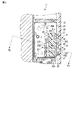
以下、図1から図8を参照して、電子機器の第1の実施形態について説明する。図1に示すように、本実施形態にかかる電子機器の一例であるテレビジョン装置11は、長方形の外観を有した薄型の表示装置である。このテレビジョン装置11は、筐体12と、筐体12を支持する脚部13と、を備えている。図2に示すように、筐体12には、開口部14が一対に設けられている。テレビジョン装置11は、開口部14にそれぞれ嵌った一対のレンズ15を有している。
Hereinafter, a first embodiment of an electronic apparatus will be described with reference to FIGS. As shown in FIG. 1, a
図1、図2に示すように、テレビジョン装置11は、チューナ基板と、テレビジョン装置11の各部を統括的に制御するシステム基板21と、例えば可撓性のあるケーブル等を介してシステム基板21に電気的に接続されたプリント配線板22と、平板状のディスプレイ23と、を筐体12の内部に備えている。ディスプレイ23は、例えば、液晶ディスプレイパネルで構成されているが、例えばプラズマディスプレイパネル等、他の種類のディスプレイパネルであってもよい。
As shown in FIGS. 1 and 2, the
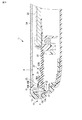
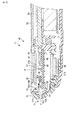
図2、3に示すように、テレビジョン装置11は、ディスプレイ23の表面を覆った透明な板状のカバー24と、プリント配線板22上に設けられた複数の第1の発光ダイオード25と、第1の発光ダイオード25の周囲を取り囲んだシェード26と、第1の発光ダイオード25とは分離した位置でプリント配線板22上に設けられた複数の第2の発光ダイオード27と、を備えている。
As shown in FIGS. 2 and 3, the
プリント配線板22上には、第1の発光ダイオード25および第2の発光ダイオード27の他に複数の回路部品28が高密度で実装されている。プリント配線板22には、レンズ15の受光部15Bの外形に沿って略三角形に設けられた切欠部31と、切欠部31の周囲を規定している縁部32と、が設けられている。
On the printed
複数の第1の発光ダイオード25は、プリント配線板22の縁部32上に並んで設けられている。本実施形態において、3個の第1の発光ダイオード25がプリント配線板22上に配置されているが、その数は3個に限定されるものではない。図2において、最も上側の位置に配置される1つ目の第1の発光ダイオード25Aは、例えば、無線LANが作動しているときに例えばオレンジ色の光を照射して、ユーザにこれを報知する。また、図2において、中間の位置に配置される2つ目の第1の発光ダイオード25Bは、例えば、内蔵する光ディスクドライブが作動している際に例えば緑色の光を照射して、ユーザにこれを報知するために用いられる。図2において、最も下側の位置に配置される3つ目の第1の発光ダイオード25Cは、例えば、内蔵するハードディスクドライブが駆動されるときに例えば赤色の光を照射して、ユーザにこれを報知するために用いられる。
The plurality of first
図2に示すように、各第1の発光ダイオード25は、レンズ15の後述する表示部15Cと受光部15Bとを結んだ直線上に設けられている。各第1の発光ダイオード25は、レンズ15の表示部15Cのほうに向いて表示部15Cに対向するように設けられている。言い換えると、各第1の発光ダイオード25は、表示部15Cに向けて光を照射するように設けられている。第1の発光ダイオード25は、プリント配線板22と平行な方向に光を照射できるいわゆる側面発光タイプの発光ダイオードである。
As shown in FIG. 2, each first
図2、図3に示すように、シェード26は、プリント配線板22上に設けられており、一対のレンズ15から外れた位置で、第1の発光ダイオード25の側面および上面を覆っている。シェード26には、2個の第1の発光ダイオード25を収容するように窪んだ第1の収容部26Aと、1個の第1の発光ダイオード25を収容するように窪んだ第2の収容部26Bと、が設けられている。シェード26は、第1の発光ダイオード25と第2の発光ダイオード27との間を仕切っており、例えば、第2の発光ダイオード27から照射される光が、第1の発光ダイオード25に対向するレンズ15に照射されないようにしている。
As shown in FIGS. 2 and 3, the
第2の発光ダイオード27は、プリント配線板22上で縁部32から外れた位置、すなわちプリント配線板22の略中央部に設けられている。本実施形態において、2個の第2の発光ダイオード27がプリント配線板22上に配置されているが、その数は2個に限定されるものではない。第2の発光ダイオード27は、いわゆる上面発光タイプのもので構成されており、プリント配線板22の延びている方向とは交差(直交)する方向に光を照射することができる。第2の発光ダイオード27のうち、一方27Aは、例えば、カバー24を透過するように光を照射して、ユーザに対して電源オンの状態を報知することができる。また、第2の発光ダイオード27のうち、他方27Bは、例えば、カバー24を透過するように光を照射して例えば、テレビジョン装置11が省電力モードにあることをユーザに報知することができる。
The second
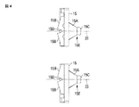
図2、図4に示すように、各レンズ15は、錐台形状の本体15Aと、本体15Aの下底部から第1の発光ダイオード25に向けて突出した複数の受光部15Bと、本体15Aの上底部にあたる位置に設けられた表示部15Cと、受光部15B同士の間の位置に設けられたくさび形の溝部15Dと、を有している。また、本体15Aと表示部15Cとによって、受光部15Bから入った光を表示部15Cの表面にまで導くための導光部15Eが構成されている。本体15A、受光部15B、および表示部15Cは、例えば、アクリル系の樹脂等の透明な材料によって一体に成形されている。本体15Aは、筐体12の開口部14の内側に嵌っている。
As shown in FIGS. 2 and 4, each
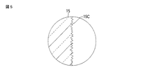
図4に示すように、レンズ15は、本体15Aの中心軸33に対して略対称形(左右対称形)をなしている。本実施形態においてレンズ15には、2個の受光部15Bが設けられている。図2に示すように、各受光部15Bは、第1の発光ダイオード25に対応するようにプリント配線板22の切欠部31の内側に嵌っている。また、表示部15Cには、受光部15Bから入った第1の発光ダイオード25からの光が表示される。図5に模式的に示すように、表示部15Cは、表面粗さが大きくなるように表面処理(シボ加工)が施されており、その表面において光を周囲に拡散することができる。
As shown in FIG. 4, the
なお、1つ目の第1の発光ダイオード25Aからの光は、図2中で上側に示されたレンズ15の表示部15Cに表示され、2つ目の第1の発光ダイオード25Bおよび3つ目の第1の発光ダイオード25Cからの光は、図2中で下側に示されたレンズ15の表示部15Cに表示される。このとき、1つ目の第1の発光ダイオード25Aは、2つ目の第1の発光ダイオード25Bおよび3つ目の第1の発光ダイオード25Cと同じようにレンズ15に対して傾けて配置されるため、1つ目の第1の発光ダイオード25Aの光量が適切な範囲に調節される。これによって、1つ目の第1の発光ダイオード25Aの見え方が他の2つ目の第1の発光ダイオード25Bや3つ目の第1の発光ダイオード25Cの見え方と同じ程度に調整され、ユーザに違和感を生ずることが防止される。
The light from the first first
第1の実施形態によれば、テレビジョン装置11は、切欠部31が設けられたプリント配線板22と、プリント配線板22上に設けられるとともにプリント配線板22と平行な方向に光を照射できる複数の第1の発光ダイオード25と、複数の第1の発光ダイオード25にそれぞれ対応するように切欠部31の内側に嵌った複数の受光部15Bと、複数の受光部15Bから入った光が表示された一つの表示部15Cと、を有した一つのレンズ15と、を具備する。
According to the first embodiment, the
この構成によれば、複数の第1の発光ダイオード25の光を一つのレンズ15で表示することができ、レンズ15の数を削減することができる。これによって、テレビジョン装置11の内部において、レンズ15が占めるスペースを削減でき、テレビジョン装置11の小型化を図ることができる。また、切欠部31の内側に受光部15Bが嵌っているため、第1の発光ダイオード25とレンズ15との距離を極力短くすることができ、第1の発光ダイオード25からの光が外部に漏れてしまうことを防止できる。また、切欠部31が設けられているため、レンズ15とプリント配線板22とが接触して、テレビジョン装置11の組み立てがうまくいかなくなる事態を生ずることを防止できる。
According to this configuration, the light from the plurality of first
また、プリント配線板22は、切欠部31の周囲を規定した縁部32を有し、各第1の発光ダイオード25は、縁部32に設けられている。この構成によれば、第1の発光ダイオード25をレンズ15の近傍に配置することができ、照明効率を向上できるとともに、周囲への光漏れを少なくすることができる。また、第1の発光ダイオード25を縁部32に配置することによって、プリント配線板22上に広い実装面積を確保することができる。
The printed
さらに、テレビジョン装置11は、開口部14が設けられるとともに、プリント配線板22および第1の発光ダイオード25を内部に収めた筐体12を具備し、レンズ15は、下底部で受光部15Bと連続するとともに上底部に表示部15Cを設けるように錐台形をなして開口部14に嵌った本体15Aを有し、各第1の発光ダイオード25は、表示部15Cと受光部15Bとを結んだ直線上に設けられるとともに、表示部15Cに向けて光を照射するように設けられている。
Further, the
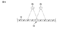
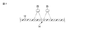
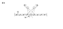
例えば、図6に模式的に示すように、第1の発光ダイオード25を筐体12から遠い位置に配置する場合には、第1の発光ダイオード25と筐体12との間に距離が確保されるため、2つの第1の発光ダイオード25からの光は、2点鎖線で示されるように、開口部14を通して筐体12の外部に照射される。しかし、図7に示すように、筐体12のコンパクト化を推し進めた結果、筐体12と第1の発光ダイオード25との間の距離を十分に確保できない場合には、第1の発光ダイオード25の光は、2点鎖線で示されるように、開口部14を通ることがなく筐体12によって遮られてしまう。上記の構成によれば、例えば、図8に示すような状態となり、筐体12と第1の発光ダイオード25との間の距離を十分に確保できない場合であっても、表示部15Cに向けて十分な光を照射することができる。これによって、表示部15Cにおける光の視認性の向上とテレビジョン装置11の筐体12の小型化とを実現することができる。
For example, as schematically shown in FIG. 6, when the first
また、レンズ15は、本体15Aの中心軸33に対して略対称形である。この構成によれば、受光部15Bが表示部15Cに対して等しい距離、等しい角度で配置されるため、表示部15Cにおいて、いずれの第1の発光ダイオード25からの光も同じ見え方にすることができる。
The
さらに、テレビジョン装置11は、プリント配線板22上に設けられるとともに、各第1の発光ダイオード25の周囲でレンズ15から外れた部分を取り囲んだシェード26を有する。この構成によれば、第1の発光ダイオード25からの光が周囲に拡散してしまうことがなく、照明の効率を向上することができる。
Furthermore, the
また、テレビジョン装置11は、プリント配線板22上で縁部32から外れた位置に設けられるとともに、プリント配線板22と交差する方向に光を照射できる第2の発光ダイオード27を具備する。この構成によれば、プリント配線板22上の縁部32に第1の発光ダイオード25を配置し、縁部32から外れた位置に第2の発光ダイオード27を配置するなど、プリント配線板22上で配置箇所を分けることで、プリント配線板22上で高密度の実装を実現することができる。
In addition, the
続いて、図9から図14を参照して、電子機器の第2の実施形態について説明する。第2の実施形態の電子機器の一例であるポータブルコンピュータ41は、外観が第1の実施形態のテレビジョン装置11とは異なっているが、主要な構成において第1の実施形態と概ね共通している。このため、主として第1の実施形態と異なる部分について説明し、共通する箇所については共通の符号を付して説明を省略する。
Next, a second embodiment of the electronic device will be described with reference to FIGS. The
また、以下の実施形態では、手前側(即ちユーザ側)を前方向F、ユーザから見て奥側を後方向R、ユーザから見て左側を左方向、ユーザから見て右側を右方向、ユーザから見て上方を上方向、ユーザから見て下方を下方向と定義する。 In the following embodiments, the front side (that is, the user side) is the front direction F, the rear side is the rear direction R when viewed from the user, the left side is the left direction when viewed from the user, the right side is the right direction when viewed from the user, The upper direction when viewed from the top is defined as the upward direction, and the lower direction when viewed from the user is defined as the downward direction.
図9に示すように、ポータブルコンピュータ41は、同図中の前方向Fに位置した第1のユニット42と、同図中の後方向Rに位置した第2のユニット43と、第1のユニット42と第2のユニット43との間に位置するとともに、これらを回転可能に連結したヒンジユニット44と、を具備している。
As shown in FIG. 9, the
第1のユニット42は、第1のケース45と、第1のケース45に取り付けられた第1のタッチパネル46と、第1のタッチパネル46の下方で第1のケース45の内側に設けられた第1のディスプレイ47と、を有している。第1のディスプレイ47は、例えば、液晶ディスプレイで構成されており、第1のタッチパネル46に隣接した位置に設けられている。また、第1のユニット42は、第1のタッチパネル46を間に挟んだ両側に一対の操作ボタン48を有している。
The
図9に示すように、第2のユニット43は、第2のケース51と、第2のケース51に取り付けられた第2のタッチパネル52と、第2のタッチパネル52の下方で第2のケース51の内側に設けられた第2のディスプレイ53と、第2のタッチパネル52に隣接した位置に設けられたパワーボタン54と、を有している。パワーボタン54は、第2のケース51に設けられた貫通孔55の内側に嵌って設けられている。筐体12は、第1のケース45と第2のケース51とで構成されている。
As shown in FIG. 9, the
図9、図13に示すように、第2のケース51は、第2のタッチパネル52および第2のディスプレイ53の前面方向の周囲を取り囲んだマスク51Aと、第2のタッチパネル52および第2のディスプレイ53の背面方向を取り囲んだカバー51Bと、を有している。図10に示すように、第2のケース51のカバー51Bには、開口部14が一対に設けられている。第2のユニット43は、開口部14にそれぞれ嵌った一対のレンズ15を有している。開口部14およびレンズ15は、後述するスピーカ56の近傍に設けられている。また、図14に示すように、マスク51Aは、一対のレンズ15の外形に対応した一対の凹部57を有している。各凹部57は、レンズ15の受光部15Bの外形に沿うように窪んでおり、この凹部57の内側に受光部15Bが嵌るようになっている。
As shown in FIGS. 9 and 13, the
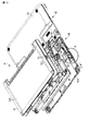
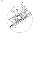
図11、図12に示すように、第2のユニット43は、CPU等が実装されたシステム基板21と、システム基板21と可撓性のケーブル等で電気的に接続されたプリント配線板22と、プリント配線板22上に設けられた複数の第1の発光ダイオード25と、第1の発光ダイオード25の周囲を取り囲んだシェード26と、第1の発光ダイオード25とは分離した位置でプリント配線板22上に設けられた複数の第2の発光ダイオード27と、プリント配線板22上に設けられてパワーボタン54の押下を検出可能なスイッチ58と、スピーカ56と、を第2のケース51の内部に備えている。
As shown in FIGS. 11 and 12, the
図11に示すように、プリント配線板22上には、第1の発光ダイオード25および第2の発光ダイオード27の他に複数の回路部品28が高密度で実装されている。プリント配線板22には、レンズ15の受光部15Bの外形に沿って略三角形に設けられた切欠部31と、切欠部31の周囲を規定している縁部32と、が設けられている。
As shown in FIG. 11, a plurality of
複数の第1の発光ダイオード25は、プリント配線板22の縁部32上に並んで設けられている。本実施形態において、3個の第1の発光ダイオード25がプリント配線板22上に配置されているが、その数は3個に限定されるものではない。図11において、最も上側の位置に配置される1つ目の第1の発光ダイオード25Aは、例えば、無線LANが作動しているときに例えばオレンジ色の光を照射して、ユーザにこれを報知する。また、図11において、中間の位置に配置される2つ目の第1の発光ダイオード25Bは、例えば、内蔵するバッテリに充電している際に例えばオレンジ色の光を照射して、ユーザにこれを報知するために用いられる。図11において、最も下側の位置に配置される3つ目の第1の発光ダイオード25Cは、例えば、内蔵するバッテリの充電が完了している状態(バッテリの電力に残量がある場合)において例えば緑色の光を照射して、ユーザにこれを報知する。
The plurality of first
図11に示すように、各第1の発光ダイオード25は、レンズ15の後述する表示部15Cと受光部15Bとを結んだ直線上に設けられている。各第1の発光ダイオード25は、表示部15Cのほうに向いて表示部15Cに対向するように設けられている。図12に示すように、第1の発光ダイオード25は、プリント配線板22と平行な方向に光を照射できるいわゆる側面発光タイプの発光ダイオードである。
As shown in FIG. 11, each 1st
図11〜図13に示すように、シェード26は、一対のレンズ15から外れた位置で、第1の発光ダイオード25の側面および上面を覆っている。シェード26には、2個の第1の発光ダイオード25を収容するように窪んだ第1の収容部26Aと、1個の第1の発光ダイオード25を収容するように窪んだ第2の収容部26Bと、が設けられている。シェード26は、第1の発光ダイオード25と第2の発光ダイオード27との間を仕切っており、例えば、第2の発光ダイオード27から照射される光が、第1の発光ダイオード25に対向するレンズ15に照射されないようにしている。
As shown in FIGS. 11 to 13, the
図11に示すように、第2の発光ダイオード27は、プリント配線板22上で縁部32から外れた位置、すなわちプリント配線板22の略中央部に設けられている。第2の発光ダイオード27は、スイッチ58の近傍に設けられている。本実施形態において、2個の第2の発光ダイオード27がプリント配線板22上に配置されているが、その数は2個に限定されるものではない。図12に示すように、第2の発光ダイオード27は、いわゆる上面発光タイプのもので構成されており、プリント配線板22の延びている方向とは交差(直交)する方向に光を照射することができる。
As shown in FIG. 11, the second
図11に示すように、第2の発光ダイオード27のうち、一方は、パワーボタン54を透過するように光を照射して、ユーザに対してポータブルコンピュータ41が電源オンの状態を報知することができる。また、第2の発光ダイオード27のうち、他方は、パワーボタン54を透過するように光を照射して例えば、ポータブルコンピュータ41が例えばサスペンド(スリープ)状態にあることをユーザに報知することができる。図12に示すように、パワーボタン54の表面には表面粗さが大きくなるように表面処理がなされており、第2の発光ダイオード27からの光を周囲に拡散することができる。
As shown in FIG. 11, one of the second
本実施形態のレンズ15は、図4に示す第1の実施形態のレンズ15と同形態である。図11、図12に示すように、レンズ15の受光部15Bは、プリント配線板22の切欠部31の内側に嵌っている。また、レンズ15の本体15Aは、第2のケース51の開口部14の内側に嵌っている。
The
第2の実施形態によれば、ポータブルコンピュータ41は、開口部14が設けられた筐体12と、筐体12の内部に収められたプリント配線板22と、プリント配線板22上に設けられるとともにプリント配線板22と平行な方向に光を照射できる複数の第1の発光ダイオード25と、複数の第1の発光ダイオード25にそれぞれ対応した複数の受光部15Bと、複数の受光部15Bから入った光が表示された一つの表示部15Cと、下底部で受光部15Bと連続するとともに上底部に表示部15Cを設けるように錐台形をなして開口部14に嵌った本体15Aと、を有した一つのレンズ15と、を具備し、各第1の発光ダイオード25は、表示部15Cと受光部15Bとを結んだ直線上に設けられるとともに、表示部15Cに向けて光を照射するように設けられている。
According to the second embodiment, the
この構成によれば、筐体12と第1の発光ダイオード25との間の距離を十分に確保できない場合であっても、表示部15Cに向けて十分な光を照射することができる。これによって、表示部15Cにおける光の視認性の向上とポータブルコンピュータ41の筐体12の小型化とを実現することができる。
According to this configuration, even when it is not possible to ensure a sufficient distance between the
電子機器は、上記実施形態に示したテレビジョン装置11、ポータブルコンピュータ41に限らず、例えば携帯電話機のようなその他の電子機器に対しても当然に実施可能である。また、上記実施形態では、レンズ15の受光部15Bとプリント配線板22の切欠部31との間のクリアランスが考慮されており、受光部15Bの一部が切欠部31の内側にわずかに嵌るのみであるが、受光部15Bをより一層第1の発光ダイオード25の近くに配置して、受光部15Bのうち切欠部31の内側に嵌っている部分を大きくしてもよい。
Of course, the electronic apparatus is not limited to the
さらに、電子機器は上記実施形態そのままに限定されるものではなく、実施段階ではその要旨を逸脱しない範囲で構成要素を変形して具体化できる。さらに、上記実施形態に開示されている複数の構成要素の適宜な組み合わせにより種々の発明を形成できる。例えば、実施形態に示される全構成要素から幾つかの構成要素を削除してもよい。更に、異なる実施形態に亘る構成要素を適宜組み合わせてもよい。 Furthermore, the electronic apparatus is not limited to the above-described embodiment as it is, and can be embodied by modifying the constituent elements without departing from the scope of the invention in the implementation stage. Furthermore, various inventions can be formed by appropriately combining a plurality of constituent elements disclosed in the embodiment. For example, some components may be deleted from all the components shown in the embodiment. Furthermore, you may combine the component covering different embodiment suitably.
11…テレビジョン装置、12…筐体、14…開口部、15…レンズ、15A…本体、15B…受光部、15C…表示部、22…プリント配線板、25…第1の発光ダイオード、26…シェード、27…第2の発光ダイオード、31…切欠部、32…縁部、33…中心軸、41…ポータブルコンピュータ
DESCRIPTION OF
Claims (14)
前記プリント配線板上に設けられるとともに前記プリント配線板と平行な方向に光を照射できる複数の第1の発光ダイオードと、
前記複数の第1の発光ダイオードにそれぞれ対応するように前記切欠部の内側に嵌った複数の受光部と、前記複数の受光部から入った前記光が表示された一つの表示部と、を有した一つのレンズと、
を具備したテレビジョン装置。 A printed wiring board provided with a notch, and
A plurality of first light emitting diodes provided on the printed wiring board and capable of irradiating light in a direction parallel to the printed wiring board;
A plurality of light receiving portions fitted inside the notches so as to correspond to the plurality of first light emitting diodes, respectively, and a display portion on which the light entering from the plurality of light receiving portions is displayed. With one lens
A television apparatus comprising:
前記各第1の発光ダイオードは、前記縁部に設けられた請求項1に記載のテレビジョン装置。 The printed wiring board has an edge that defines the periphery of the notch,
The television apparatus according to claim 1, wherein each of the first light emitting diodes is provided at the edge.
前記レンズは、本体を有し、この本体は、下底部で前記受光部と連続するとともに上底部に前記表示部を設けるように錐台形をなして前記開口部に嵌っており、
前記各第1の発光ダイオードは、前記表示部と前記受光部とを結んだ直線上に設けられるとともに、前記表示部に向けて前記光を照射するように設けられた請求項2に記載のテレビジョン装置。 An opening is provided, and includes a housing in which the printed wiring board and the first light emitting diode are housed.
The lens has a main body, and the main body is continuous with the light receiving unit at the lower bottom and is fitted into the opening in a frustum shape so as to provide the display unit on the upper bottom.
3. The television according to claim 2, wherein each of the first light emitting diodes is provided on a straight line connecting the display unit and the light receiving unit, and is provided to irradiate the light toward the display unit. John equipment.
前記プリント配線板上に設けられるとともに前記プリント配線板と平行な方向に光を照射できる複数の第1の発光ダイオードと、
前記複数の第1の発光ダイオードにそれぞれ対応するとともに前記切欠部の内側に嵌った複数の受光部と、前記複数の受光部から入った前記光が表示された一つの表示部と、を有した一つのレンズと、
を具備した電子機器。 A printed wiring board provided with a notch, and
A plurality of first light emitting diodes provided on the printed wiring board and capable of irradiating light in a direction parallel to the printed wiring board;
A plurality of light receiving portions respectively corresponding to the plurality of first light emitting diodes and fitted inside the notch portions, and one display portion on which the light entering from the plurality of light receiving portions is displayed. With one lens,
An electronic device comprising
前記各第1の発光ダイオードは、前記縁部に設けられた請求項7に記載の電子機器。 The printed wiring board has an edge that defines the periphery of the notch,
The electronic device according to claim 7, wherein each of the first light emitting diodes is provided at the edge.
前記レンズは、本体を有し、この本体は、下底部で前記受光部と連続するとともに上底部に前記表示部を設けるように錐台形をなして前記開口部に嵌っており、
前記各第1の発光ダイオードは、前記表示部と前記受光部とを結んだ直線上に設けられるとともに、前記表示部に向けて前記光を照射するように設けられた請求項8に記載の電子機器。 An opening is provided, and includes a housing in which the printed wiring board and the first light emitting diode are housed.
The lens has a main body, and the main body is continuous with the light receiving unit at the lower bottom and is fitted into the opening in a frustum shape so as to provide the display unit on the upper bottom.
9. The electron according to claim 8, wherein each of the first light emitting diodes is provided on a straight line connecting the display unit and the light receiving unit, and is provided so as to irradiate the light toward the display unit. machine.
前記筐体の内部に収められたプリント配線板と、
前記プリント配線板上に設けられるとともに前記プリント配線板と平行な方向に光を照射できる複数の第1の発光ダイオードと、
前記複数の第1の発光ダイオードにそれぞれ対応した複数の受光部と、前記複数の受光部から入った前記光が表示された一つの表示部と、下底部で前記受光部と連続するとともに上底部に前記表示部を設けるように錐台形をなして前記開口部に嵌った本体と、を有した一つのレンズと、
を具備し、
前記各第1の発光ダイオードは、前記表示部と前記受光部とを結んだ直線上に設けられるとともに、前記表示部に向けて前記光を照射するように設けられた電子機器。 A housing provided with an opening,
A printed wiring board housed in the housing;
A plurality of first light emitting diodes provided on the printed wiring board and capable of irradiating light in a direction parallel to the printed wiring board;
A plurality of light receiving portions respectively corresponding to the plurality of first light emitting diodes, a display portion on which the light entering from the plurality of light receiving portions is displayed, and an upper bottom portion that is continuous with the light receiving portion at a lower bottom portion A lens having a frustum shape so as to provide the display portion, and fitted into the opening, and
Comprising
Each of the first light emitting diodes is provided on a straight line connecting the display unit and the light receiving unit, and is provided so as to irradiate the light toward the display unit.
前記筐体に収容され、切欠部が設けられたプリント配線板と、
前記プリント配線板の前記切欠部近傍に設けられた複数の第1の発光ダイオードと、
前記プリント配線板の前記切欠部内に少なくとも一部が位置されて前記複数の第1の発光ダイオードにそれぞれ対応した複数の受光部と、前記複数の受光部からの光を前記開口部に導く一つの導光部と、を有したレンズと、
を具備した電子機器。 A housing provided with an opening,
A printed wiring board housed in the housing and provided with a notch, and
A plurality of first light emitting diodes provided in the vicinity of the notch of the printed wiring board;
A plurality of light-receiving portions that are at least partially located in the cutout portions of the printed wiring board and respectively correspond to the plurality of first light-emitting diodes, and one light that guides light from the plurality of light-receiving portions to the opening A lens having a light guide, and
An electronic device comprising
Priority Applications (3)
| Application Number | Priority Date | Filing Date | Title |
|---|---|---|---|
| JP2010139794A JP4792120B1 (en) | 2010-06-18 | 2010-06-18 | Television equipment, electronic equipment |
| US13/082,252 US8218094B2 (en) | 2010-06-18 | 2011-04-07 | Television apparatus and electronic apparatus |
| US13/481,547 US8780281B2 (en) | 2010-06-18 | 2012-05-25 | Television apparatus and electronic apparatus |
Applications Claiming Priority (1)
| Application Number | Priority Date | Filing Date | Title |
|---|---|---|---|
| JP2010139794A JP4792120B1 (en) | 2010-06-18 | 2010-06-18 | Television equipment, electronic equipment |
Related Child Applications (1)
| Application Number | Title | Priority Date | Filing Date |
|---|---|---|---|
| JP2011155960A Division JP4902007B2 (en) | 2011-07-14 | 2011-07-14 | Television equipment, electronic equipment |
Publications (2)
| Publication Number | Publication Date |
|---|---|
| JP4792120B1 true JP4792120B1 (en) | 2011-10-12 |
| JP2012004973A JP2012004973A (en) | 2012-01-05 |
Family
ID=44881959
Family Applications (1)
| Application Number | Title | Priority Date | Filing Date |
|---|---|---|---|
| JP2010139794A Active JP4792120B1 (en) | 2010-06-18 | 2010-06-18 | Television equipment, electronic equipment |
Country Status (2)
| Country | Link |
|---|---|
| US (2) | US8218094B2 (en) |
| JP (1) | JP4792120B1 (en) |
Families Citing this family (3)
| Publication number | Priority date | Publication date | Assignee | Title |
|---|---|---|---|---|
| JP4792120B1 (en) | 2010-06-18 | 2011-10-12 | 株式会社東芝 | Television equipment, electronic equipment |
| WO2013047595A1 (en) | 2011-09-26 | 2013-04-04 | 日本電気株式会社 | Power connection control system and method |
| US11523165B1 (en) * | 2021-07-29 | 2022-12-06 | Albert Garcia | Television remote finder assembly |
Family Cites Families (12)
| Publication number | Priority date | Publication date | Assignee | Title |
|---|---|---|---|---|
| US5083192A (en) | 1990-04-30 | 1992-01-21 | Kulicke And Soffa Industries, Inc. | Cluster mount for high intensity leds |
| JPH0529164A (en) | 1991-07-24 | 1993-02-05 | Sanyo Electric Works Ltd | Neon transformer |
| JP3549834B2 (en) * | 2000-11-29 | 2004-08-04 | Necアクセステクニカ株式会社 | Lens structure |
| JP2003234507A (en) | 2002-02-07 | 2003-08-22 | Koha Co Ltd | Side-emitting LED lamp |
| CA2410978A1 (en) * | 2002-11-04 | 2004-05-04 | John Spencer | Solid state illuminator for bi-colour ported water level gauges |
| JP2004200120A (en) * | 2002-12-20 | 2004-07-15 | Sharp Corp | Lighting device and amusement device using the same |
| JP4577555B2 (en) * | 2004-08-25 | 2010-11-10 | 横河電機株式会社 | Light guide member and display using the same |
| WO2006093889A2 (en) * | 2005-02-28 | 2006-09-08 | Color Kinetics Incorporated | Configurations and methods for embedding electronics or light emitters in manufactured materials |
| JP5168780B2 (en) * | 2005-12-22 | 2013-03-27 | パナソニック株式会社 | Light guide plate structure |
| JP2008084990A (en) * | 2006-09-26 | 2008-04-10 | Matsushita Electric Works Ltd | Light emitting device and lighting apparatus |
| JP2008258094A (en) | 2007-04-09 | 2008-10-23 | M & S Fine Tec Kk | LED backlight and liquid crystal display device |
| JP4792120B1 (en) | 2010-06-18 | 2011-10-12 | 株式会社東芝 | Television equipment, electronic equipment |
-
2010
- 2010-06-18 JP JP2010139794A patent/JP4792120B1/en active Active
-
2011
- 2011-04-07 US US13/082,252 patent/US8218094B2/en not_active Expired - Fee Related
-
2012
- 2012-05-25 US US13/481,547 patent/US8780281B2/en active Active
Also Published As
| Publication number | Publication date |
|---|---|
| US8218094B2 (en) | 2012-07-10 |
| US8780281B2 (en) | 2014-07-15 |
| US20110310311A1 (en) | 2011-12-22 |
| US20120229713A1 (en) | 2012-09-13 |
| JP2012004973A (en) | 2012-01-05 |
Similar Documents
| Publication | Publication Date | Title |
|---|---|---|
| US20120090973A1 (en) | Illuminated membrane keyboard | |
| KR20220050237A (en) | Control deⅵce | |
| JP3130331U (en) | Keypad light emitting assembly | |
| JP4792120B1 (en) | Television equipment, electronic equipment | |
| US7340273B2 (en) | Portable communication terminal with improved light emission structure | |
| US20070227867A1 (en) | Integrating structure of switch plates | |
| JP6026247B2 (en) | Lighting structure of operation panel | |
| JP5580728B2 (en) | Small electrical equipment | |
| JP5775607B2 (en) | Car interior lighting system | |
| JP5546010B2 (en) | emblem | |
| JP4902007B2 (en) | Television equipment, electronic equipment | |
| JP2010015794A (en) | Light guide sheet switch unit | |
| JP6224718B2 (en) | Illumination device | |
| CN101004624A (en) | Information processing apparatus | |
| US20090091933A1 (en) | Keypad assembly and portable electronic device using the same | |
| JP4901982B2 (en) | Electronics | |
| US10295381B2 (en) | Indicator | |
| JP2014071982A (en) | Lighting device | |
| TWM258818U (en) | Saw blade hood with lighting device | |
| TWM469798U (en) | Luminous mirror structure | |
| KR101148389B1 (en) | Laser Navigation Module | |
| JP6174324B2 (en) | Input device for portable electronic device and portable electronic device | |
| CN201765995U (en) | Luminous key set and luminous assembly for the luminous key set | |
| JP2025139648A (en) | Card slot and card reader | |
| JP2011014428A (en) | Illumination device |
Legal Events
| Date | Code | Title | Description |
|---|---|---|---|
| TRDD | Decision of grant or rejection written | ||
| A01 | Written decision to grant a patent or to grant a registration (utility model) |
Free format text: JAPANESE INTERMEDIATE CODE: A01 Effective date: 20110628 |
|
| A01 | Written decision to grant a patent or to grant a registration (utility model) |
Free format text: JAPANESE INTERMEDIATE CODE: A01 |
|
| A61 | First payment of annual fees (during grant procedure) |
Free format text: JAPANESE INTERMEDIATE CODE: A61 Effective date: 20110722 |
|
| FPAY | Renewal fee payment (event date is renewal date of database) |
Free format text: PAYMENT UNTIL: 20140729 Year of fee payment: 3 |
|
| R151 | Written notification of patent or utility model registration |
Ref document number: 4792120 Country of ref document: JP Free format text: JAPANESE INTERMEDIATE CODE: R151 |
|
| S111 | Request for change of ownership or part of ownership |
Free format text: JAPANESE INTERMEDIATE CODE: R313117 Free format text: JAPANESE INTERMEDIATE CODE: R313121 |
|
| R350 | Written notification of registration of transfer |
Free format text: JAPANESE INTERMEDIATE CODE: R350 |