JP4784536B2 - Air transport device for lightweight containers - Google Patents
Air transport device for lightweight containers Download PDFInfo
- Publication number
- JP4784536B2 JP4784536B2 JP2007068185A JP2007068185A JP4784536B2 JP 4784536 B2 JP4784536 B2 JP 4784536B2 JP 2007068185 A JP2007068185 A JP 2007068185A JP 2007068185 A JP2007068185 A JP 2007068185A JP 4784536 B2 JP4784536 B2 JP 4784536B2
- Authority
- JP
- Japan
- Prior art keywords
- container
- air
- guide rail
- air injection
- conveyance
- Prior art date
- Legal status (The legal status is an assumption and is not a legal conclusion. Google has not performed a legal analysis and makes no representation as to the accuracy of the status listed.)
- Active
Links
Images


Description
本発明は、ペットボトル等の軽量容器の首部を支持して空気流による推進力で搬送する軽量容器の空気搬送装置に関するものである。 The present invention relates to an air conveyance device for a lightweight container that supports a neck portion of a lightweight container such as a PET bottle and conveys it with a propulsive force by an air flow.
従来、ペットボトル等の軽量容器を起立姿勢で搬送する搬送コンベアとして、容器の首部に形成されているフランジ部の下面を案内レールで支持すると共に、容器の後方から空気を吹き付けて、その推進力により案内レール上を滑らせて搬送するようにした空気搬送コンベア装置が知られており、例えば、特許文献1が開示されている。
Conventionally, as a transport conveyor for transporting lightweight containers such as PET bottles in an upright position, the lower surface of the flange formed on the neck of the container is supported by a guide rail, and air is blown from the rear of the container, and its propulsive force There is known an air conveyance conveyor device that is slid and conveyed on a guide rail. For example,
特許文献1の空気搬送コンベア装置は、案内レールの直下に空気噴射口が斜め上向きに設けられ、空気噴射口から容器の鍔部に向けて噴射される空気流により容器が進行方向の推力と共に、容器のフランジ部が浮上方向の推力を受けるように構成されており、搬送時に容器を浮上させることにより、フランジ部と案内レールとの摺動抵抗を軽減して容器の搬送エネルギー効率を向上するようにしている。
In the air conveyance conveyor device of
ところが、上記構成の空気搬送コンベア装置では、フランジ部を浮上させることによって容器の搬送負荷を軽減できるが、一方では、フランジ部が案内レールより浮上することで搬送容器のふらつきや首振り現象が発生し易くなっており、よって、容器搬送の安定性に欠けるという問題があった。
本発明は、上記の問題点に鑑みなされたもので、搬送時の容器のふらつきや首振り現象を抑制し、容器を円滑に搬送できる軽量容器の空気搬送装置を提供することを目的としている。 The present invention has been made in view of the above-described problems, and an object of the present invention is to provide a lightweight container air transport device that can smoothly transport a container while suppressing wobbling and swinging of the container during transport.
すなわち、請求項1に記載の発明は、首部にフランジ部が形成された容器のフランジ部下面を、搬送方向に沿って対向配置された一対の案内レールにて支持すると共に、前記容器に空気流を作用させて、前記案内レールの上面に前記容器のフランジ部を摺動させながら搬送する軽量容器の空気搬送装置において、前記案内レールの直下に、前記容器側に空気噴射口が開口する多数の空気噴射ノズルを備えた長尺板状のノズル板を前記容器の搬送方向に沿って設けてなり、かつ前記空気噴射ノズルは、平面視において、前記空気流が導入される上流側端部から前記空気噴射口側に向けて漸次前記搬送方向側へと傾斜するように前記ノズル板に設けた案内溝の上部開口部が塞がれることにより形成されるとともに、上記案内レールの下面部分において斜め下方に傾斜して形成されることにより、当該空気噴射口より噴射される空気流の動圧が前記容器の肩部に作用して前記容器が搬送方向の推力を受けつつ、降下方向の推力を受けるように構成したことを特徴としている。 That is, according to the first aspect of the present invention, the lower surface of the flange portion of the container having the flange portion formed on the neck portion is supported by a pair of guide rails arranged to face each other along the conveying direction, and the air flow is applied to the container. In a lightweight container air transport device that transports while sliding the flange portion of the container on the upper surface of the guide rail, a large number of air injection ports open on the container side immediately below the guide rail . A long plate-like nozzle plate provided with an air injection nozzle is provided along the conveying direction of the container, and the air injection nozzle is arranged in a plan view from the upstream end where the air flow is introduced. An upper opening portion of a guide groove provided in the nozzle plate is closed so as to gradually incline toward the conveyance direction side toward the air injection port side, and at the lower surface portion of the guide rail. Te by being formed to be inclined obliquely downward, while the container dynamic pressure of the air flow ejected from the air ejection nozzle acts on the shoulder of the container is subjected to thrust in the conveying direction, of the descent direction It is characterized by being configured to receive thrust.
請求項1に記載の発明によれば、空気噴射口より噴射される空気流により容器が搬送方向の推力を受けつつ、降下方向の推力を受けるように構成したので、降下方向に発生する推力により、容器搬送時のフランジ部の浮上が防止され、容器の浮上により生じる容器のふらつきや首振り現象を抑制して容器の搬送姿勢を安定化させることができる。これにより、容器を円滑に搬送することができる。 According to the first aspect of the present invention, the container is configured to receive the thrust in the descending direction while receiving the thrust in the transport direction by the air flow ejected from the air ejection port. As a result, the flange portion is prevented from rising when the container is transported, and the container's wobbling or swinging phenomenon caused by the container's floating can be suppressed to stabilize the container transport posture. Thereby, a container can be conveyed smoothly.
ところで、このような噴射空気により搬送される容器においては、支承点となるフランジ部と重心との間であって重心側近傍にあたる肩部は、噴射空気による推進力が最も有効に作用し、且つ、容器を搬送方向にふらつかせることなく安定的に搬送できる部位となる。
この点、空気噴射口より噴射される空気の動圧が容器の肩部に作用するように構成しているために、上記のように、推進力が最も有効に作用する容器の肩部に推進動圧を集中することができ、且つ、空気噴射口が肩部に近接するように設けられているため、容器搬送エネルギーを有効に利用した効率的な搬送が可能となる。
また、容器の肩部(水平方向搬送最適力点)に推進動圧を集中させることにより、従来の搬送装置で発生していた容器フランジ部の案内レールへの過剰な押し付け力による案内レールの摩耗や搬送動力の増大を最小限に抑制することができる。
By the way, in such a container transported by the blast air, the propulsive force by the blast air is most effectively applied to the shoulder portion between the flange portion serving as a support point and the centroid and in the vicinity of the centroid side, and The container can be stably transported without causing the container to stagger in the transport direction.
In this respect , since the dynamic pressure of the air injected from the air injection port is configured to act on the shoulder of the container, as described above, the propulsive force is propelled to the shoulder of the container. Since the dynamic pressure can be concentrated and the air injection port is provided so as to be close to the shoulder portion, efficient conveyance using the container conveyance energy effectively becomes possible.
In addition, by concentrating the propulsive dynamic pressure on the shoulder of the container (horizontal conveyance optimum force point), the guide rail wear and tear caused by excessive pressing force on the guide rail of the container flange generated in the conventional conveyance device An increase in conveyance power can be suppressed to a minimum.
また、容器の搬送路の上部および両側部をカバー部材で覆うようにすれば、異物が混入し易い空気ダクト内雰囲気から搬送路を隔離することができ、これにより容器の開口部から容器内部に異物が浸入するのを防止することができる。 Further, if the top and sides of the transport path of the container Migihitsuji covered by the cover member, foreign matter can be isolated transport path from mixed easily air duct atmosphere inside the container thereby the opening of the container It is possible to prevent foreign matter from entering the surface.
以下、図面に基づいて本発明の軽量容器の空気搬送装置の一実施形態を説明する。図1は空気搬送装置の内部構成を示し、図2は空気搬送装置の要部を示し、図3は上面視による搬送路を示し、図4は容器の搬送状態を示している。
尚、本実施形態では、上記軽量容器としてペットボトルが例示されている。
上記ペットボトルWは、上端に飲み口となる開口部15を有し、その下方にフランジ部16を設けた細径の首部18と、この首部18より下方に向けて徐々に拡径される肩部17と、この肩部17より底部21に至る大径の胴部19とを備えている。
Hereinafter, an embodiment of an air conveyance device for a lightweight container according to the present invention will be described with reference to the drawings. FIG. 1 shows an internal configuration of the air transfer device, FIG. 2 shows a main part of the air transfer device, FIG. 3 shows a transfer path in a top view, and FIG. 4 shows a transfer state of the container.
In the present embodiment, a PET bottle is exemplified as the lightweight container.
The plastic bottle W has an opening 15 serving as a drinking mouth at the upper end, a
図1中、符号10は容器Wの搬送路5を覆う四角形状の空気ダクトで、この空気ダクト10内に、図示しない加圧空気供給源(例えば、送風機)から所定圧力の空気(加圧空気)がダクトを介して供給されるようになっている。
In FIG. 1,
この空気ダクト10内の左右の下部側壁には、容器Wの搬送路5に沿って固定フレーム1が設けられ、各々固定フレーム1の上面が空気ダクト10の幅方向に設けた取付部材4にネジ止めされていると共に、各々固定フレーム1の下面に、所定の間隔を持って相平行する一対の支持部材2、2が固定されている。そして、これらの支持部材2の内側端部、すなわち、空気ダクト10の幅方向の中央部に、容器Wの空気搬送機構20が配設されている。
A
また、図1、図4に示すように、容器Wの胴部19下部の近傍には、容器Wを両側より支持して起立姿勢で搬送される容器Wの横ぶれを防止するガイドレール3が所定の間隔を持って、各容器サイズに合わせて上下複数箇所(本実施形態においては3カ所)に設けられている。
As shown in FIGS. 1 and 4, in the vicinity of the lower portion of the
上記空気搬送機構20は、図2に示すように、容器Wが搬送される搬送路5を備え、そして、この搬送部5を含む搬送空間7を密閉に近い状態に維持している。この搬送空間7は、上部が密閉板14(カバー部材)で覆われ、且つ、両側部が取付部材4にネジ止めされた左右一対の固定部材6、6(カバー部材)にて覆われることにより形成されている。
As shown in FIG. 2, the
そして、各固定部材6の下部フランジ6aと各支持部材2の間には、空気案内用の溝8(案内溝8)が多数形成された長尺板状のノズル板9がそれぞれ搬送路5に沿って設けられていると共に、このノズル板9の上面に容器Wのフランジ部16の下面を両側より支持する一対の案内レール12、12が設けられ、これらノズル板9と案内レール12が締結部材13によりフランジ6aと支持部材2に挟持された状態で固定されている。
案内溝8の上部開口部が上記したフランジ部6aと案内レール12の下面にて塞がれることにより、空気噴射ノズル11が形成される。この空気噴射ノズル11の上流側端部は空気ダクト10内に開放されており、下流側端部の空気噴射口8aは容器W側に開放されている。
A long plate-
When the upper opening of the
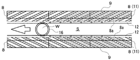
上記ノズル板9に設けた多数の案内溝8は、図3に示すように、平面視において、上流側端部から空気噴出口8a側に向けて漸次搬送方向側へと傾斜して設けられており、且つ、これらの案内溝8は、上記案内レール12の下面部分において、図2に示すように、斜め下方に傾斜させて形成され、これにより、空気噴射口8aから噴射される空気流による推力を容器Wの搬送方向に指向させると共に、容器搬送方向に対して斜め下方向、すなわち、水平方向搬送最適力点に指向させるようになっている。
As shown in FIG. 3, the plurality of
また、本実施形態では、搬送空間7を形成する左右一対の固定部材6の高さ方向中央に、嵌め込み式の密閉板14を取り付けできるようになっており、図示しないが、この密閉板14に搬送空間7内の過剰動圧を回収する吸引板や、搬送方向と同一方向に空気を噴射する噴射口板、或いは搬送方向と反対方向に空気を噴射する噴射口板等を必要に応じて取り付けできるようになっている。
In the present embodiment, a fitting
上記構成の軽量容器の空気搬送装置では、加圧空気供給源(例えば、図示しない送風機)から供給される加圧空気が空気ダクト10内に導入されると、空気ダクト10内の加圧空気は、図4に示すように、案内溝8(すなわち、空気噴射ノズル11)を通して空気噴射口8aより容器Wの肩部17に向かって噴射され、この空気の動圧よって容器Wが搬送方向の推力を受け、容器Wは案内レール12に沿って搬送される。
この際に、このような噴射空気により搬送される容器Wにおいては、案内レール12により支持され、搬送容器の支承点となるフランジ部16と重心Pとの間であって重心P側近傍にあたる肩部17は、噴射空気による推進力が最も有効に作用し、且つ、容器Wを搬送方向にふらつかせることなく安定的に搬送できる部位となる。
In the air transport device for a lightweight container having the above-described configuration, when pressurized air supplied from a pressurized air supply source (for example, a blower (not shown)) is introduced into the
At this time, the container W transported by such blast air is supported by the
そして、本実施形態では、空気噴射ノズル11の先端側を斜め下方に傾斜させているので、空気噴射口8aより噴射される空気が肩部17に当たると、その動圧力により、容器Wが搬送方向の推力を受けつつ、容器Wのフランジ部16が降下方向の推力を受けることになり、この下方向の推力により、容器Wのフランジ部16の浮上が防止され、フランジ部16が案内レール12上に支持された状態で摺動する。この結果、容器Wが浮上することにより生じる容器Wのふらつきや首振り現象が抑制され、容器Wの搬送姿勢を安定化させることができる。これにより、容器Wを円滑に搬送することができるようになる。
And in this embodiment, since the front end side of the
また、搬送方向の両側に配置された空気噴射口8aより斜め下方向に噴射される空気は、最も有効な推進力の作用点にあたる容器Wの肩部17であって案内レール12間の中央部に集中し、且つ、空気噴射口8aが容器Wの肩部17に近接するように設けられているため、搬送に必要な動力(搬送エネルギー)を有効に利用した効率的で安定した搬送が可能となる。
また、容器の肩部に推進動圧を集中させることにより、従来の搬送装置で発生していた容器フランジ部の案内レールへの過剰な押し付け力による案内レールの摩耗や搬送動力の増大を最小限に抑制することができる。
Further, the air jetted obliquely downward from the
In addition, by concentrating the propulsive dynamic pressure on the shoulder of the container, the wear of the guide rail and the increase in transport power due to the excessive pressing force of the container flange on the guide rail, which has been generated in the conventional transport device, are minimized. Can be suppressed.
また、容器Wの搬送路5の上部と両側部を、カバー部材となる密閉板14と固定部材6で覆う構造としたので、異物が混入し易い空気ダクト10内雰囲気より搬送路5を隔離することができ、これにより、容器Wの開口部15から容器W内部に異物が浸入するのを防止することができる。
Further, since the upper portion and both side portions of the
また、図示しないが、搬送空間7を形成する左右一対の固定部材6を取付部材4よりフリーな構造とすると共に、密閉板14および支持部材2に伸縮自在なスライド部材を取り付けて、上記各固定部材6を幅方向に移動可能にすることにより、首部18の外径が異なる容器Wに対しても、自動または手動にて容易に型替えができるようになる。
Although not shown, the pair of left and right fixing
5 搬送路
6 カバー部材(固定部材)
8a 空気噴射口
12 案内レール
14 カバー部材(密閉板)
17 肩部
18 首部
16 フランジ部
W 容器
5
8a
17
Claims (1)
前記案内レールの直下に、前記容器側に空気噴射口が開口する多数の空気噴射ノズルを備えた長尺板状のノズル板を前記容器の搬送方向に沿って設けてなり、
かつ前記空気噴射ノズルは、平面視において、前記空気流が導入される上流側端部から前記空気噴射口側に向けて漸次前記搬送方向側へと傾斜するように前記ノズル板に設けた案内溝の上部開口部が塞がれることにより形成されるとともに、上記案内レールの下面部分において斜め下方に傾斜して形成されることにより、当該空気噴射口より噴射される空気流の動圧が前記容器の肩部に作用して前記容器が搬送方向の推力を受けつつ、降下方向の推力を受けるように構成したことを特徴とする軽量容器の空気搬送装置。 The lower surface of the flange portion of the container having a flange portion formed on the neck portion is supported by a pair of guide rails arranged to face each other along the transport direction, and an air flow is applied to the container so that the upper surface of the guide rail is In an air conveyance device for a lightweight container that conveys while sliding the flange portion of the container,
Immediately below the guide rail, a long plate-like nozzle plate provided with a large number of air injection nozzles having air injection openings opened on the container side is provided along the conveyance direction of the container,
The air injection nozzle has a guide groove provided in the nozzle plate so as to gradually incline from the upstream end where the air flow is introduced toward the air injection port toward the conveyance direction in plan view. The upper opening of the guide rail is closed, and the lower surface portion of the guide rail is inclined obliquely downward, so that the dynamic pressure of the air flow injected from the air injection port is the container. An air transport device for a lightweight container, wherein the container is configured to receive a thrust in a descending direction while acting on the shoulder of the container while the container receives a thrust in the transport direction.
Priority Applications (1)
| Application Number | Priority Date | Filing Date | Title |
|---|---|---|---|
| JP2007068185A JP4784536B2 (en) | 2007-03-16 | 2007-03-16 | Air transport device for lightweight containers |
Applications Claiming Priority (1)
| Application Number | Priority Date | Filing Date | Title |
|---|---|---|---|
| JP2007068185A JP4784536B2 (en) | 2007-03-16 | 2007-03-16 | Air transport device for lightweight containers |
Publications (2)
| Publication Number | Publication Date |
|---|---|
| JP2008230713A JP2008230713A (en) | 2008-10-02 |
| JP4784536B2 true JP4784536B2 (en) | 2011-10-05 |
Family
ID=39903983
Family Applications (1)
| Application Number | Title | Priority Date | Filing Date |
|---|---|---|---|
| JP2007068185A Active JP4784536B2 (en) | 2007-03-16 | 2007-03-16 | Air transport device for lightweight containers |
Country Status (1)
| Country | Link |
|---|---|
| JP (1) | JP4784536B2 (en) |
Families Citing this family (1)
| Publication number | Priority date | Publication date | Assignee | Title |
|---|---|---|---|---|
| JP2016088662A (en) * | 2014-10-31 | 2016-05-23 | 三友機器株式会社 | Container air carrying device |
Family Cites Families (1)
| Publication number | Priority date | Publication date | Assignee | Title |
|---|---|---|---|---|
| US5161919A (en) * | 1991-08-06 | 1992-11-10 | Simplimatic Engineering Company | Bottle air conveyor |
-
2007
- 2007-03-16 JP JP2007068185A patent/JP4784536B2/en active Active
Also Published As
| Publication number | Publication date |
|---|---|
| JP2008230713A (en) | 2008-10-02 |
Similar Documents
| Publication | Publication Date | Title |
|---|---|---|
| JP4006045B2 (en) | Bottle conveyor | |
| JP4791479B2 (en) | Conveyor for adjusting device used to position object in position | |
| JPH05162852A (en) | Pneumatic bottle conveyor | |
| JP4784536B2 (en) | Air transport device for lightweight containers | |
| US8484796B2 (en) | Air rinse and transport apparatus | |
| JP2006335564A (en) | Floating carrying device for plate-like material and flat bottom-like material | |
| JP2002137825A (en) | Pneumatic carrying conveyor device for light vessel | |
| KR101470660B1 (en) | Air floatation conveyance device and method of conveyance using air | |
| JP3635549B2 (en) | Structure of PET bottle transport path | |
| JP2720774B2 (en) | Air flow conveyor device for conveying molding containers | |
| JP4779376B2 (en) | Air conveyor | |
| JP2009040598A (en) | Air floatation transportation device, air floatation unit, and air floatation transportation method | |
| JP2799107B2 (en) | Conveyor conveyor for lightweight containers | |
| JP4149146B2 (en) | Air jet conveyor | |
| JP2010247977A (en) | Transfer device, transfer method, and aseptic filling system | |
| JP2007044620A (en) | Washing apparatus | |
| JP5540271B2 (en) | Preform transfer device | |
| JP2000272753A (en) | Bottle carrying device | |
| JP4660304B2 (en) | Transport device | |
| JP5853392B2 (en) | Article assembly device | |
| JP2007106566A (en) | Air conveyor | |
| JP2005324956A (en) | Orientation restricting device of square container | |
| SE519571C2 (en) | Device for handling packaging containers with collar neck and neck collar support strip | |
| JP5440875B2 (en) | Plate-shaped body transfer device | |
| JP6419622B2 (en) | Air conveyor |
Legal Events
| Date | Code | Title | Description |
|---|---|---|---|
| A131 | Notification of reasons for refusal |
Free format text: JAPANESE INTERMEDIATE CODE: A131 Effective date: 20100928 |
|
| A521 | Request for written amendment filed |
Free format text: JAPANESE INTERMEDIATE CODE: A523 Effective date: 20101117 |
|
| TRDD | Decision of grant or rejection written | ||
| A01 | Written decision to grant a patent or to grant a registration (utility model) |
Free format text: JAPANESE INTERMEDIATE CODE: A01 Effective date: 20110614 |
|
| A01 | Written decision to grant a patent or to grant a registration (utility model) |
Free format text: JAPANESE INTERMEDIATE CODE: A01 |
|
| A61 | First payment of annual fees (during grant procedure) |
Free format text: JAPANESE INTERMEDIATE CODE: A61 Effective date: 20110627 |
|
| R150 | Certificate of patent or registration of utility model |
Ref document number: 4784536 Country of ref document: JP Free format text: JAPANESE INTERMEDIATE CODE: R150 Free format text: JAPANESE INTERMEDIATE CODE: R150 |
|
| FPAY | Renewal fee payment (event date is renewal date of database) |
Free format text: PAYMENT UNTIL: 20140722 Year of fee payment: 3 |
|
| R250 | Receipt of annual fees |
Free format text: JAPANESE INTERMEDIATE CODE: R250 |
|
| R250 | Receipt of annual fees |
Free format text: JAPANESE INTERMEDIATE CODE: R250 |
|
| R250 | Receipt of annual fees |
Free format text: JAPANESE INTERMEDIATE CODE: R250 |
|
| R250 | Receipt of annual fees |
Free format text: JAPANESE INTERMEDIATE CODE: R250 |
|
| R250 | Receipt of annual fees |
Free format text: JAPANESE INTERMEDIATE CODE: R250 |
|
| R250 | Receipt of annual fees |
Free format text: JAPANESE INTERMEDIATE CODE: R250 |
|
| R250 | Receipt of annual fees |
Free format text: JAPANESE INTERMEDIATE CODE: R250 |
|
| R250 | Receipt of annual fees |
Free format text: JAPANESE INTERMEDIATE CODE: R250 |
|
| R250 | Receipt of annual fees |
Free format text: JAPANESE INTERMEDIATE CODE: R250 |
|
| R250 | Receipt of annual fees |
Free format text: JAPANESE INTERMEDIATE CODE: R250 |