JP4783000B2 - Processing machine - Google Patents
Processing machine Download PDFInfo
- Publication number
- JP4783000B2 JP4783000B2 JP2004282409A JP2004282409A JP4783000B2 JP 4783000 B2 JP4783000 B2 JP 4783000B2 JP 2004282409 A JP2004282409 A JP 2004282409A JP 2004282409 A JP2004282409 A JP 2004282409A JP 4783000 B2 JP4783000 B2 JP 4783000B2
- Authority
- JP
- Japan
- Prior art keywords
- workpiece
- work
- heat
- heating
- cooling
- Prior art date
- Legal status (The legal status is an assumption and is not a legal conclusion. Google has not performed a legal analysis and makes no representation as to the accuracy of the status listed.)
- Expired - Fee Related
Links
- 238000010438 heat treatment Methods 0.000 claims description 106
- 238000001816 cooling Methods 0.000 claims description 96
- 238000006243 chemical reaction Methods 0.000 claims description 19
- 239000012530 fluid Substances 0.000 description 88
- 230000009471 action Effects 0.000 description 27
- 238000000034 method Methods 0.000 description 26
- 239000003507 refrigerant Substances 0.000 description 26
- 238000003754 machining Methods 0.000 description 22
- 230000020169 heat generation Effects 0.000 description 20
- 238000010521 absorption reaction Methods 0.000 description 19
- 239000000463 material Substances 0.000 description 18
- 230000007246 mechanism Effects 0.000 description 13
- 239000004065 semiconductor Substances 0.000 description 13
- 230000000694 effects Effects 0.000 description 12
- 238000006073 displacement reaction Methods 0.000 description 11
- XLYOFNOQVPJJNP-UHFFFAOYSA-N water Substances O XLYOFNOQVPJJNP-UHFFFAOYSA-N 0.000 description 11
- CURLTUGMZLYLDI-UHFFFAOYSA-N Carbon dioxide Chemical compound O=C=O CURLTUGMZLYLDI-UHFFFAOYSA-N 0.000 description 10
- 235000011089 carbon dioxide Nutrition 0.000 description 10
- 230000008859 change Effects 0.000 description 10
- 238000009833 condensation Methods 0.000 description 8
- 230000005494 condensation Effects 0.000 description 8
- 230000008569 process Effects 0.000 description 8
- 239000002826 coolant Substances 0.000 description 7
- 230000017525 heat dissipation Effects 0.000 description 4
- 239000011810 insulating material Substances 0.000 description 4
- 239000004020 conductor Substances 0.000 description 3
- 230000002542 deteriorative effect Effects 0.000 description 3
- 239000000696 magnetic material Substances 0.000 description 3
- 230000005855 radiation Effects 0.000 description 3
- IJGRMHOSHXDMSA-UHFFFAOYSA-N Atomic nitrogen Chemical compound N#N IJGRMHOSHXDMSA-UHFFFAOYSA-N 0.000 description 2
- 230000015556 catabolic process Effects 0.000 description 2
- 238000006731 degradation reaction Methods 0.000 description 2
- 230000000593 degrading effect Effects 0.000 description 2
- 230000005674 electromagnetic induction Effects 0.000 description 2
- 235000013611 frozen food Nutrition 0.000 description 2
- 238000002844 melting Methods 0.000 description 2
- 230000008018 melting Effects 0.000 description 2
- 239000002184 metal Substances 0.000 description 2
- 238000003672 processing method Methods 0.000 description 2
- 230000009467 reduction Effects 0.000 description 2
- 238000005507 spraying Methods 0.000 description 2
- 230000005679 Peltier effect Effects 0.000 description 1
- 229910000831 Steel Inorganic materials 0.000 description 1
- 230000002411 adverse Effects 0.000 description 1
- 239000000919 ceramic Substances 0.000 description 1
- 239000003795 chemical substances by application Substances 0.000 description 1
- 230000003247 decreasing effect Effects 0.000 description 1
- 230000003111 delayed effect Effects 0.000 description 1
- 238000001514 detection method Methods 0.000 description 1
- 238000010586 diagram Methods 0.000 description 1
- 238000004090 dissolution Methods 0.000 description 1
- 238000005553 drilling Methods 0.000 description 1
- 230000003631 expected effect Effects 0.000 description 1
- 239000007789 gas Substances 0.000 description 1
- 239000007788 liquid Substances 0.000 description 1
- 238000012986 modification Methods 0.000 description 1
- 230000004048 modification Effects 0.000 description 1
- 229910052757 nitrogen Inorganic materials 0.000 description 1
- 230000000191 radiation effect Effects 0.000 description 1
- 239000010959 steel Substances 0.000 description 1
Images


Description
本発明は、加工機械に関する。例えば、ワークに対して、切削、研削、穴あけ等の加工を行う加工機械に関する。 The present invention relates to a processing machine. For example, the present invention relates to a processing machine that performs processing such as cutting, grinding, and drilling on a workpiece.
従来、工具を用いてワークの加工を行う加工機械としては、ワークを保持するワーク保持手段と、工具を保持する工具保持手段と、ワーク保持手段および工具保持手段を相対移動させる相対移動手段とを備えた加工機械が知られている。
このような加工機械を用いてワークを加工するには、まず、ワークをワーク保持手段に固定し、その加工に適した工具を工具保持手段に取付ける。次に、工具を高速回転させながら、相対移動手段によってワーク保持手段と工具保持手段とを相対移動させる。このようにして、ワークを加工機械で加工することができる。
Conventionally, as a processing machine for processing a workpiece using a tool, a workpiece holding unit that holds a workpiece, a tool holding unit that holds a tool, and a relative movement unit that relatively moves the workpiece holding unit and the tool holding unit. Processing machines equipped are known.
In order to machine a workpiece using such a processing machine, first, the workpiece is fixed to the workpiece holding means, and a tool suitable for the machining is attached to the tool holding means. Next, the work holding means and the tool holding means are relatively moved by the relative moving means while rotating the tool at a high speed. In this way, the workpiece can be processed by the processing machine.
しかし、ワークの硬度や常温での状態など、ワークの材質によって加工しにくい場合がある。例えば、鋼のように硬度が高い場合では、加工時の発熱によって、工具の切削性能が低下するなどの問題がある。また、冷凍食品のように常温で融解する場合では、融解するとワークが弾性を持ち正確な加工ができないことや、ワークの質の低下などが考えられ、また、迅速な加工が要求されるため丁寧な加工ができないという課題がある。
このため、従来の加工機械では、ワークが高硬度である場合に、工具に冷却剤を噴射させながら加工を行い工具の硬度低下を防止する方法や、加工時に発生した熱を熱電気変換素子によって吸収する方法(特許文献1参照)、また、ワークが常温で状態変化を伴う材質である場合に、作業室の室温を下げることよってワークの状態を維持する方法などの工夫が採られている。
However, it may be difficult to process depending on the material of the workpiece, such as the hardness of the workpiece and the state at room temperature. For example, when the hardness is high like steel, there is a problem that the cutting performance of the tool is lowered due to heat generated during processing. Also, when melting at room temperature, such as frozen foods, it is possible that the workpiece will be elastic when it is melted and cannot be accurately processed, and the quality of the workpiece may be degraded. There is a problem that it cannot be processed easily.
For this reason, in a conventional processing machine, when the workpiece has a high hardness, a method of preventing a decrease in the hardness of the tool by performing a process while injecting a coolant onto the tool, or heat generated during processing by a thermoelectric conversion element. There are devised methods such as a method of absorbing (see Patent Document 1) and a method of maintaining the state of the work by lowering the room temperature of the work chamber when the work is made of a material that changes state at room temperature.
しかし、工具に冷却剤を噴射しながら加工を行う方法や、特許文献1に記載の方法は、工具の切削性能を保つために工具またはワークを局部的に冷却させるものであるため、ワークの材質による加工困難性は依然として解決されていない。
特に、工具に冷却剤を噴射しながら加工を行う方法では、冷却剤が作業者の身体に噴射される危険性や、冷却剤によって作業部分の視界が悪くなるなどの加工作業の支障、さらに冷却剤を循環使用するための設備費等がかかるなどの問題がある。また、作業室の室温を下げる方法では、冷房装置など設備が大型化し、かつ、低温の中での作業となるので、加工作業以外のエネルギーや手間が必要となる。
However, since the method of performing processing while spraying a coolant on the tool and the method described in Patent Document 1 are for locally cooling the tool or the workpiece in order to maintain the cutting performance of the tool, the material of the workpiece The processing difficulty due to is still not solved.
In particular, in the method of performing processing while spraying coolant on the tool, there is a risk of coolant being sprayed on the worker's body, troubles in processing work such as poor visibility of the work part due to coolant, and cooling. There are problems such as the cost of equipment for circulating the agent. Further, in the method of lowering the room temperature of the work chamber, the equipment such as the cooling device is enlarged and the work is performed at a low temperature, so that energy and labor other than the machining work are required.
本発明の目的は、ワークの材質に合わせて、最も効率的な加工を実現することのできる加工機械を提供することである。 An object of the present invention is to provide a processing machine capable of realizing the most efficient processing according to the material of a workpiece.
本発明の加工機械は、上面にワークを載置するテーブルを有するワーク保持手段と、ワークを加工する工具を保持する工具保持手段と、ワーク保持手段および工具保持手段を相対移動させる相対移動手段とを有し、前記テーブルに内蔵され前記テーブルの上面を加熱する加熱手段を備え、前記加熱手段は、電気エネルギーを熱エネルギーに変換する電気熱変換手段によって構成されていることを特徴とする。 The processing machine of the present invention includes a work holding means having a table for placing a work on the upper surface, a tool holding means for holding a tool for processing the work, a relative movement means for relatively moving the work holding means and the tool holding means, And heating means built in the table for heating the upper surface of the table , wherein the heating means is constituted by electrothermal conversion means for converting electrical energy into thermal energy .
このような構成によれば、加熱手段によって、ワークの材質に合わせてワークを加熱し、ワークの硬度を工具によって加工しやすい程度まで変化させることができる。よってワークの加工がしやすくなる。また、加熱手段によってワークの温度を維持し、ワークの状態変化を抑えることができるので、ワークの品質を低下させることなく加工でき、かつ、加工作業が受ける時間の制約を軽減することができる。これらにより、加工機械は、ワークの材質に合わせて最も効率的な加工を実現することができる。
さらに、加熱手段がテーブルに内蔵され、加熱されたテーブルの上面とワークとの接触面における熱伝達によってワークを加熱するので、ワーク保持手段の外部からの加熱に比べ、作業を円滑、安全に行うことができる。また、加熱手段がテーブルに内蔵され、加熱されたテーブルの上面とワークとの接触面における熱伝達によってワークを加熱するので、工具は加熱されにくく、加熱による工具の切削性能の低下を少なくできる。
According to such a configuration, by the heating means, in accordance with the material of the workpiece to heat the workpiece, it is possible to vary the hardness of the work to the extent that easy machining by the tool. Therefore, it becomes easy to process the workpiece. In addition, since the temperature of the workpiece can be maintained by the heating means and the change in the state of the workpiece can be suppressed, machining can be performed without deteriorating the quality of the workpiece, and the restriction on the time taken by the machining operation can be reduced. As a result, the processing machine can realize the most efficient processing according to the material of the workpiece.
Furthermore, since the heating means is built in the table and the workpiece is heated by heat transfer at the contact surface between the upper surface of the heated table and the workpiece, the work is smoothly and safely performed compared to heating from the outside of the workpiece holding means. be able to. Further, since the heating means is built in the table and the workpiece is heated by heat transfer at the contact surface between the upper surface of the heated table and the workpiece, the tool is difficult to be heated , and the degradation of the cutting performance of the tool due to heating can be reduced.
さらに、テーブルに内蔵された加熱手段としての電気熱変換手段が、電気エネルギーを熱エネルギーに変換し、この熱エネルギーによってワーク保持手段を加熱する。さらに、加熱されたテーブルの上面とワークとの接触面における熱伝達によってワークが加熱される。この熱伝達による加熱方法は、ワーク保持手段の外部からワークを加熱するのに比べ、作業を円滑、安全に行うことができる。さらに、これより工具は加熱されにくいので、熱による工具の切削性能の低下を少なくできる。 Furthermore, an electrothermal converting means as a heating means built in the table converts electric energy into heat energy, and the work holding means is heated by this heat energy. Furthermore, the workpiece is heated by heat transfer at the contact surface between the upper surface of the heated table and the workpiece. This heating method by heat transfer can perform the work smoothly and safely compared to heating the workpiece from the outside of the workpiece holding means. Furthermore, since the tool is less likely to be heated, the reduction in the cutting performance of the tool due to heat can be reduced.
本発明の加工機械は、上面にワークを載置するテーブルを有するワーク保持手段と、ワークを加工する工具を保持する工具保持手段と、ワーク保持手段および工具保持手段を相対移動させる相対移動手段とを有し、前記テーブルに内蔵され前記テーブルの上面を冷却する冷却手段を備え、前記冷却手段は、ペルチェ素子を含む回路によって構成されていることを特徴とする。 The processing machine of the present invention includes a work holding means having a table for placing a work on the upper surface, a tool holding means for holding a tool for processing the work, a relative movement means for relatively moving the work holding means and the tool holding means, have been incorporated in the table provided with a cooling means for cooling the upper surface of said table, said cooling means, characterized in that it is constituted by a circuit including a Peltier element.
このような構成によれば、冷却手段によって、ワークの材質に合わせてワークを冷却し、ワークの硬度を工具によって加工しやすい程度まで変化させることができる。よってワークの加工がしやすくなる。また、冷却手段によってワークの温度を維持し、ワークの状態変化を抑えることができるので、ワークの品質を低下させることなく加工でき、かつ、加工作業が受ける時間の制約を軽減することができる。これらにより、加工機械は、ワークの材質に合わせて最も効率的な加工を実現することができる。
さらに、冷却手段がテーブルに内蔵され、冷却されたテーブルの上面とワークとの接触面における熱伝達によってワークを冷却するので、ワーク保持手段の外部からの冷却に比べ、作業を円滑、安全に行うことができる。また、冷却手段がテーブルに内蔵され、冷却されたテーブルの上面とワークとの接触面における熱伝達によってワークを冷却するので、工具は冷却されにくく、冷却による工具表面における結露の発生を少なくできる。
本発明で冷却手段として用いるペルチェ素子は、種類の異なるペルチェ素子を接続し直流電流を流すと、接続部分の一端側で発熱作用が生じ他端側で吸熱作用が生じる。
よって、このような構成によれば、異なるペルチェ素子を接続したものを有する回路に直流電流を流すことによって、ペルチェ素子の接続部の一端側、他端側にそれぞれ発熱作用と吸熱作用を生じさせ、このペルチェ素子の吸熱作用によってテーブルの上面を冷却することができる。そして、冷却されたテーブルの上面とワークの接触面における熱伝達によって、ワークを冷却することができる。
熱伝達によってワークを冷却することから、ワーク保持手段の外部からワークを冷却するのに比べ作業を円滑、安全に行うことができる。さらに、これにより工具は冷却されにくいので、冷却による工具表面における結露の発生などを少なくできる。
According to such a configuration, the cooling means can cool the work in accordance with the material of the work, and can change the hardness of the work to such an extent that it can be easily processed by the tool. Therefore, it becomes easy to process the workpiece. In addition, since the temperature of the workpiece can be maintained by the cooling means and the change in the state of the workpiece can be suppressed, machining can be performed without deteriorating the quality of the workpiece, and the restriction on the time taken by the machining operation can be reduced. As a result, the processing machine can realize the most efficient processing according to the material of the workpiece.
Furthermore, since the cooling means is built in the table and the work is cooled by heat transfer at the contact surface between the upper surface of the cooled table and the work, the work is smoothly and safely performed compared to cooling from the outside of the work holding means. be able to. Further, since the cooling means is built in the table and the work is cooled by heat transfer at the contact surface between the upper surface of the cooled table and the work, the tool is not easily cooled, and the occurrence of condensation on the tool surface due to the cooling can be reduced.
When the Peltier elements used as the cooling means in the present invention are connected to different types of Peltier elements and a direct current flows, a heat generating action is generated on one end side of the connecting portion and an endothermic action is generated on the other end side.
Therefore, according to such a configuration, by causing a direct current to flow through a circuit having different Peltier elements connected to each other, a heat generating action and a heat absorbing action are generated on one end side and the other end side of the connection part of the Peltier elements, respectively. The upper surface of the table can be cooled by the endothermic action of the Peltier element. And a workpiece | work can be cooled by the heat transfer in the upper surface of the cooled table, and the contact surface of a workpiece | work.
Since the work is cooled by heat transfer, the work can be smoothly and safely performed compared to cooling the work from the outside of the work holding means. Furthermore, this makes it difficult for the tool to be cooled, so that the occurrence of condensation on the tool surface due to cooling can be reduced.
本発明の加工機械は、上面にワークを載置するテーブルを有するワーク保持手段と、ワークを加工する工具を保持する工具保持手段と、ワーク保持手段および工具保持手段を相対移動させる相対移動手段とを有し、前記テーブルに内蔵され前記テーブルの上面を加熱する加熱手段と、前記テーブルに内蔵され前記テーブルの上面を冷却する冷却手段とを備え、前記加熱手段および冷却手段は、ペルチェ素子を含む発熱・吸熱回路によって構成されていることを特徴とする。 The processing machine of the present invention includes a work holding means having a table for placing a work on the upper surface, a tool holding means for holding a tool for processing the work, a relative movement means for relatively moving the work holding means and the tool holding means, anda heating means for heating the upper surface of the table is built in the table, is built into the table and a cooling means for cooling the upper surface of said table, said heating means and cooling means, a Peltier element It is characterized by comprising a heat generation / heat absorption circuit.
このような構成によれば、加熱手段および冷却手段によって、ワークの材質に合わせてワークを加熱あるいは冷却し、ワークの硬度を工具によって加工しやすい程度まで変化させることができる。よってワークの加工がしやすくなる。また、加熱手段および冷却手段によってワークの温度を維持し、ワークの状態変化を抑えることができるので、ワークの品質を低下させることなく加工でき、かつ、加工作業が受ける時間の制約を軽減することができる。これらにより、加工機械は、ワークの材質に合わせて最も効率的な加工を実現することができる。
さらに、加熱手段および冷却手段がテーブルに内蔵され、加熱または冷却されたテーブルの上面とワークとの接触面における熱伝達によってワークを冷却するので、ワーク保持手段の外部からの加熱または冷却に比べ、作業を円滑、安全に行うことができる。また、加熱および冷却手段がテーブルに内蔵され、加熱または冷却されたテーブルの上面とワークとの接触面における熱伝達によってワークを冷却するので、工具は加熱または冷却されにくく、加熱による工具の切削性能の低下を少なくでき、あるいは、冷却による工具表面における結露の発生を少なくできる。
本発明で加熱手段および冷却手段として用いるペルチェ素子は、種類の異なるペルチェ素子を接続し直流電流を流すと、接続部分の一端側で発熱作用が生じ他端側で吸熱作用が生じる。つまり、異なるペルチェ素子を接続したものを有する発熱・吸熱回路に直流電流を流すことによって、ペルチェ素子の接続部の一端側、他端側にそれぞれ発熱現象と吸熱現象を生じさせる。
よって、このような構成によれば、ワークを加熱する場合は、このペルチェ素子の発熱現象によってテーブルの上面を加熱することができ、ワークを冷却する場合は、このペルチェ素子の吸熱現象によってテーブルの上面を冷却することができる。加熱および冷却されたテーブルの上面とワークの接触面における熱伝達によって、ワークを温度調整することができる。
According to such a configuration, the heating means and the cooling means can heat or cool the work in accordance with the material of the work, and can change the hardness of the work to such an extent that it can be easily processed by the tool. Therefore, it becomes easy to process the workpiece. Also, since the temperature of the workpiece can be maintained by the heating means and cooling means, and changes in the state of the workpiece can be suppressed, machining can be performed without deteriorating the quality of the workpiece, and the time limit for the machining operation can be reduced. Can do. As a result, the processing machine can realize the most efficient processing according to the material of the workpiece.
Furthermore, since the heating means and the cooling means are built in the table and the work is cooled by heat transfer at the contact surface between the upper surface of the heated and cooled table and the work, compared to heating or cooling from the outside of the work holding means, Work can be done smoothly and safely. In addition, since the heating and cooling means are built into the table and the workpiece is cooled by heat transfer at the contact surface between the heated and cooled table top surface and the workpiece, the tool is difficult to be heated or cooled, and the cutting performance of the tool by heating Can be reduced, or the occurrence of condensation on the tool surface due to cooling can be reduced.
When the Peltier elements used as the heating means and the cooling means in the present invention are connected to different types of Peltier elements and a direct current flows, a heat generation effect occurs at one end side of the connection portion and an endothermic effect occurs at the other end side. That is, by causing a direct current to flow through a heat generation / heat absorption circuit having different Peltier elements connected thereto, a heat generation phenomenon and a heat absorption phenomenon are generated on one end side and the other end side of the connection part of the Peltier elements, respectively.
Therefore, according to such a configuration, when the work is heated , the upper surface of the table can be heated by the heat generation phenomenon of the Peltier element, and when the work is cooled, the heat absorption phenomenon of the Peltier element is used to cool the work table. The top surface can be cooled. The temperature of the workpiece can be adjusted by heat transfer on the upper surface of the heated and cooled table and the contact surface of the workpiece.
これにより、加熱手段および冷却手段の役割をペルチェ素子の加熱および吸熱現象によって果たすことができ、ワークの加熱および冷却の両方を行うことができる。熱伝達によってワークを温度調整することから、ワーク保持手段の外部からワークを加熱および冷却するのに比べ作業を円滑、安全に行うことができ、さらに、工具は加熱および冷却されにくいので、熱による工具の切削性能の低下や、冷却による工具表面における結露の発生などを少なくできる。また、ペルチェ素子を流れる直流電流の向きを変えることによって、ペルチェ素子の発熱作用および吸熱作用が生じる位置が切り替わるので、ワークの加熱および冷却を瞬時に切り替えることができる。 Thereby, the role of a heating means and a cooling means can be fulfill | performed by the heating and endothermic phenomenon of a Peltier device, and both a heating and cooling of a workpiece | work can be performed. Since the temperature of the workpiece is adjusted by heat transfer, the work can be performed smoothly and safely compared to heating and cooling the workpiece from the outside of the workpiece holding means, and furthermore, the tool is difficult to heat and cool. Reduction of the cutting performance of the tool and generation of condensation on the tool surface due to cooling can be reduced. Also, by changing the direction of the direct current flowing through the Peltier element, the position where the Peltier element generates heat and absorbs heat is switched, so that heating and cooling of the workpiece can be switched instantaneously.
以下、本発明の実施形態を図面に基づいて説明する。各実施形態の説明にあたって、同一構成については、同一符号を配し、その説明を省略する。
<第1実施形態>
図1に、第1実施形態の加工機械の斜視図、図2に、第1実施形態のワーク保持手段の模式断面図を示す。
第1実施形態の加工機械は、工具とワークを相対移動させながら、ワークを工具によって加工する機械であって、図1のように、工具とワークの相対移動を行う相対移動手段1と、工具を保持する工具保持手段2と、上面にワークを保持するワーク保持手段3と、ワーク保持手段3に内蔵されワークを加熱する加熱手段4と、相対移動手段1および工具保持手段2の駆動を制御する制御手段(図示省略)とを備える。
Hereinafter, embodiments of the present invention will be described with reference to the drawings. In the description of each embodiment, the same components are denoted by the same reference numerals, and the description thereof is omitted.
<First Embodiment>
FIG. 1 is a perspective view of the processing machine of the first embodiment, and FIG. 2 is a schematic cross-sectional view of the work holding means of the first embodiment.
The processing machine according to the first embodiment is a machine that processes a workpiece with a tool while relatively moving the tool and the workpiece, and as shown in FIG. 1, a relative movement unit 1 that relatively moves the tool and the workpiece, and a tool The tool holding means 2 for holding the workpiece, the workpiece holding means 3 for holding the workpiece on the upper surface, the heating means 4 for heating the workpiece incorporated in the workpiece holding means 3, the relative movement means 1 and the drive of the tool holding means 2 are controlled. Control means (not shown).
相対移動手段1は、ワーク保持手段3に対して、可動部材であるZ軸スライダ132を互いに直交する三軸方向(X軸方向、Y軸方向およびZ軸方向)へ移動させる3つの軸駆動機構を備えて構成されている。つまり、相対移動手段1は、Y軸駆動機構12、X軸駆動機構11、および、Z軸駆動機構13を備えて構成されている。
The relative movement means 1 is a three-axis drive mechanism that moves the Z-
Y軸駆動機構12は、前後方向に沿って配置された左右一対のガイドレール121と、このガイドレール121間に掛け渡されたY軸ビーム122と、このY軸ビーム122をガイドレール121に沿って前後方向(Y軸方向)へ移動させるリニアモータ123とから構成されている。一方のガイドレール121とY軸ビーム122の一端側との間には、Y軸ビーム122のY軸方向の位置(移動変位量)を検出する変位検出器124が設けられている。変位検出器124は、一方のガイドレール121に沿って配設されたスケール125と、Y軸ビーム122の一端側にスケール125に対して僅かなギャップを介して対向配置された検出ヘッド126とから構成されている。
The Y-
X軸駆動機構11は、Y軸ビーム122上に移動可能に設けられたX軸スライダ111と、このX軸スライダ111をY軸ビーム122に沿って左右方向(X軸方向)へ移動させるリニアモータ112とから構成されている。X軸スライダ111とY軸ビーム122との間には、X軸スライダ111のX軸方向の位置(移動変位量)を検出する変位検出器(図示省略)が設けられている。この変位検出器は、変位検出器124と同じ構成であるため、説明を省略する。
The X-axis drive mechanism 11 includes an
Z軸駆動機構13は、X軸スライダ111に取付けられ上下方向に沿って伸びるZ軸ガイドプレート131と、このZ軸ガイドプレート131に沿って移動可能に設けられたZ軸スライダ(可動部材)132と、このZ軸スライダ132をZ軸ガイドプレート131に沿って上下方向へ移動させるリニアモータ133とから構成されている。Z軸ガイドプレート131とZ軸スライダ132との間には、Z軸スライダ132のZ軸方向の位置(移動変位量)を検出する変位検出器(図示省略)が設けられている。この変位検出器も、変位検出器124と同じ構成であるため、説明を省略する。
The Z-
工具保持手段2は、Z軸スライダ132に設置されたホルダ本体21と、ホルダ本体21の下端から下方に向かって伸び、軸中心に回転駆動を行う主軸22と、主軸22の下端に形成され工具を挟持するチャック機構23とから形成されている。チャック機構23に挟持された工具は、主軸22と一体的に回転駆動を行う。またホルダ本体21は、主軸22に回転駆動を与える動力源、例えば、モータ(図示省略)に接続されている。
The tool holding means 2 includes a holder
ワーク保持手段3は、熱伝達性および強度を十分に有する金属製部材であり、平面板のベース31と、ベース31の上面に固定され、上面にワークを載置するテーブル32とを備えている。テーブル32は、上面の温度を計測・表示するテーブル温度計測器33と、上面に120度間隔で配置され中心へ向かって同時に進退可能に構成された3つのチャック片34と、これら3つのチャック片34を同時に進退させる開閉用駆動源(図示省略)とを備えている。チャック片34は、熱伝導性を持ち、開閉用駆動源によって移動されテーブル32の上面に載置したワークを挟持して固定する。
The work holding means 3 is a metal member having sufficient heat transfer properties and strength, and includes a
加熱手段4は、図2のように、テーブル32に内蔵され電気エネルギーを熱エネルギーに変換する電気熱変換手段41と、テーブル32に内蔵され、電気熱変換手段41の一部を被覆する断熱部材42とから構成される。
電気熱変換手段41は、発熱作用を行うヒータ411と、電源412と、ヒータの温度調整、つまり、電源412の電圧調整を行う制御装置413と、これら3つの部材を直列に連結する環状の導線414とから構成される回路である。
ヒータ411は、テーブル32の上縁部に、テーブル32のほぼ全面に広がって配置されている。
制御装置413は、外面に設置されたコンロトールパネルがテーブル32から露出しており、テーブル32の上面の温度に対応した電圧値をコントロールパネルによって入力することで、電源412の電圧を調節することができる。
断熱部材42は、ヒータ411の上面を除く全ての面を被覆している。
As shown in FIG. 2, the heating means 4 includes an electrothermal conversion means 41 that is built in the table 32 and converts electrical energy into heat energy, and a heat insulating member that is built in the table 32 and covers a part of the electrothermal conversion means 41. 42.
The electrothermal converting
The
The
The
制御手段は、相対移動手段1およびワーク保持手段3とは別体であって、相対移動手段1の駆動、および、工具の回転速度を調節する。制御手段は、相対移動手段1および工具保持手段2に接続され、各軸駆動機構11,12,13およびモータの駆動量を信号で送信することで、これらの駆動を制御する。
The control means is separate from the relative movement means 1 and the work holding means 3, and adjusts the drive of the relative movement means 1 and the rotational speed of the tool. The control means is connected to the relative movement means 1 and the tool holding means 2, and controls the drive of each
第1実施形態の加工機械を用いたワークの加工方法を説明する。
工具保持手段2の主軸22に形成されたチャック機構23に加工に適した工具を挟持させ、ワーク保持手段3のテーブル32の上面にワークを載置し、チャック片34によって固定する。
次に、加熱手段4の電気熱変換手段41の制御装置413に備えられたコントロールパネルを操作して回路に電圧を与える。すると、ヒータ411によって電気エネルギーが熱エネルギーに変換され、ヒータ411は、この熱エネルギーによってテーブル32の上縁部を加熱する。さらに、テーブル32の上縁部の熱伝達によってテーブル32の上面およびチャック片34の温度が上昇し、テーブル32の上面に固定されたワークが加熱される。このとき、ヒータ411の上面を除く全ての面を断熱部材42で被覆していることから、ヒータ411から発生される熱によって、テーブル側縁部および下縁部が加熱されることはない。テーブル32の上面の温度は、制御装置413によって電源412の電圧を制御することで調節し、また、図1のテーブル温度計測器33が表示する計測値によって確認することができる。
A workpiece machining method using the machining machine according to the first embodiment will be described.
A tool suitable for processing is clamped by the
Next, a voltage is applied to the circuit by operating a control panel provided in the
このようにして、ワークを加工に適した温度まで加熱し、ワークの温度が安定した後、相対移動手段1の各軸駆動機構11,12,13、および、工具保持手段2のモータの適切な駆動量を、制御手段に入力する。この入力信号に従って各軸駆動機構11,12,13、および、モータが駆動し、ワークに対し工具が高速回転しながら相対移動を行ってワークが加工される。
In this way, after the workpiece is heated to a temperature suitable for processing and the temperature of the workpiece is stabilized, each
第1実施形態によれば、次のような効果が期待できる。
(1)ワークの材質に合わせてワークを加熱し、ワークの硬度を加工しやすい程度
にまで軟化させることができる。これにより、ワークの加工がしやすくなり、ワークの材質に合わせて最も効率的な加工を実現することができる。
(2)ワークを加熱してその温度を維持し、ワークの状態変化を抑えることができ
るので、ワークの品質を低下させることなく加工でき、かつ、加工作業が受ける時間の制約を軽減することができる。これにより、ワークの材質に合わせて最も効率的な加工を実現することができる。
According to the first embodiment, the following effects can be expected.
(1) The workpiece can be heated in accordance with the material of the workpiece, and the hardness of the workpiece can be softened to such an extent that it can be easily processed. Thereby, it becomes easy to process the workpiece, and the most efficient processing can be realized according to the material of the workpiece.
(2) Since the workpiece can be heated to maintain its temperature and the change in the workpiece state can be suppressed, the workpiece can be processed without degrading the quality of the workpiece, and the time limit for the machining operation can be reduced. it can. Thereby, the most efficient processing can be realized according to the material of the workpiece.
(3)ヒータ411がワーク保持手段3に内蔵され、加熱されたテーブル32の上
縁部とワークとの接触面における熱伝達によってワークを加熱するので、ワーク保持手段3の外部からの加熱に比べ、作業を円滑、安全に行うことができる。
(4)ヒータ411がワーク保持手段3に内蔵され、加熱されたテーブル32の上
縁部とワークとの接触面における熱伝達によってワークを加熱するので、工具は加熱されにくく、熱による工具の切削性能の低下を少なくできる。
(5)加熱手段4に頻繁に交換しなければならない部材がないので、交換作業の手
間を省くことができる。
(3) Since the
(4) Since the
(5) Since there is no member that needs to be frequently replaced in the heating means 4, it is possible to save labor for replacement.
(6)制御装置413を用いて電源412の電圧、つまり、ヒータ411の発熱量
を調節できるから、ワークを適切な温度で維持することができる。
(7)ヒータ411の上面を除く全ての面を断熱部材42で被覆していることから
、ヒータ411から発生される熱によって、テーブル32の側縁部および下縁部が加熱されすぎることはなく、熱によるワーク保持手段の変形、損傷を比較的少なくできる。
(6) Since the voltage of the
(7) Since all surfaces except the upper surface of the
第1実施形態では、加熱手段4はテーブル32に内蔵されているとしたが、少なくともヒータ411のみがテーブル32の上縁部に内蔵されていればよく、ヒータ411を除く加熱手段4の各部材はテーブル32の外部に設置されていてもよい。
In the first embodiment, the
<第2実施形態>
図3に、第2実施形態のワーク保持手段の模式断面図を示す。なお、この第2実施形態は、テーブルの上面を加熱するものではなく、本発明には含まれない。
第2実施形態は、第1実施形態に対して、ワーク保持手段3および加熱手段5が異なる。
第2実施形態のワーク保持手段3は、非磁性体で構成されている点が第1実施形態のワーク保持手段3と異なる。
Second Embodiment
FIG. 3 shows a schematic cross-sectional view of the work holding means of the second embodiment. In addition, this 2nd Embodiment does not heat the upper surface of a table, and is not contained in this invention.
The second embodiment differs from the first embodiment in the work holding means 3 and the heating means 5.
The work holding means 3 of the second embodiment is different from the work holding means 3 of the first embodiment in that it is made of a non-magnetic material.
第2実施形態の加熱手段5は、図3のように、テーブル32に内蔵された磁場発生手段51から構成される。
磁場発生手段51は、電流を通すことで磁場を発生する複数個のコイル511と、電源512と、磁場の大きさを調節、つまり、電源512の電圧の調節を行う制御装置513と、コイル511、電源512、および、制御装置513を直列に連結する環状の導線514とから構成された回路である。
複数個のコイル511は、テーブル32の上縁部に並んで配置されている。
制御装置513は、外面に設置されたコンロトールパネルがテーブル32から露出しており、テーブル32の上面の温度に対応した電圧値をコントロールパネルによって入力することで、電源512の電圧を調節することができる。
The heating means 5 of 2nd Embodiment is comprised from the magnetic field generation means 51 incorporated in the table 32 like FIG.
The magnetic field generating means 51 includes a plurality of
The plurality of
The
第2実施形態の加工機械を用いたワークの加工方法は、第1実施形態で前述した加工方法に対して、加熱手段4による加熱作用が加熱手段5による加熱作用になる点を除いて同様である。よって、ここでは加熱手段5による加熱作用のみを説明する。
加熱手段5の磁場発生装置51を用いて、IH加熱(電磁誘導加熱)によりワークを加熱する。まず、磁場発生手段51の制御装置513に設置されたコントロールパネルを操作して、回路に電圧を与える。すると、コイル511に直流電流が流れ電磁誘導によりコイル周辺に磁場が発生する。テーブル32の上面に固定されたワークが磁性体である場合、磁力戦がワーク内部を通過することにより、ワーク内部に渦電流が発生し、この渦電流のジュール熱によってワークが加熱される。このとき、テーブル32は非磁性体であるので、テーブル32の内部に渦電流は発生せず、テーブル32は加熱されない。ワークの温度は、磁場の大きさを調節、つまり、制御装置413によって電源412の電圧を制御することで調節可能である。
The workpiece machining method using the machining machine of the second embodiment is the same as the machining method described in the first embodiment except that the heating action by the heating means 4 becomes the heating action by the heating means 5. is there. Therefore, only the heating action by the heating means 5 will be described here.
The workpiece is heated by IH heating (electromagnetic induction heating) using the
第2実施形態によって、第1実施形態で得られる作用効果(1)および(2)に加え、次のような作用効果を期待できる。
(8)ワーク保持手段3が非磁性体であることから、磁場発生手段51から発生す
る磁場はワーク保持手段3を加熱しないので、作業を円滑、安全に行うことができる。
(9)磁場発生手段51から発生する磁場によってワークが加熱されるので、磁場
の大きさを調節することで、工具が加熱されにくく、熱による工具の性能低下を少なくできる。
According to the second embodiment, the following operational effects can be expected in addition to the operational effects (1) and (2) obtained in the first embodiment.
(8) Since the work holding means 3 is a non-magnetic material, the magnetic field generated from the magnetic field generating means 51 does not heat the work holding means 3, so that the work can be performed smoothly and safely.
(9) Since the workpiece is heated by the magnetic field generated from the magnetic field generating means 51, the tool is hardly heated by adjusting the magnitude of the magnetic field, and the performance degradation of the tool due to heat can be reduced.
(10)ワーク保持手段3の内部に熱が発生することはないので、磁場発生手段51の周囲に断熱部材を設置する必要はない。
(11)加熱手段5に頻繁に交換しなければならない部材がないので、交換作業の手間を省くことができる。
(12)制御装置513を用いて電源512の電圧、つまり、コイル511から発生される磁場の大きさを調節できるから、ワークを適切な温度に維持できる。
(10) Since no heat is generated inside the work holding means 3, it is not necessary to install a heat insulating member around the magnetic field generating means 51.
(11) Since there is no member that needs to be frequently replaced in the heating means 5, it is possible to save the labor of replacement.
(12) Since the voltage of the
第2実施形態では、加熱手段5は、テーブル32に内蔵されているとしたが、少なくともコイル511のみがテーブル32の上縁部に内蔵されていればよく、コイル511を除く加熱手段5の各部材はテーブル32の外部に設置されていてもよい。
In the second embodiment, the heating means 5 is built in the table 32, but it is sufficient that at least only the
<第3実施形態>
図4に、第3実施形態のワーク保持手段の模式断面図を示す。
第3実施形態は、第1実施形態に対して、加熱手段4が省略され、それに代わってワークを冷却する冷却手段6が付加されている点が異なる。
なお、この第3実施形態は、冷却手段が異なる(後述する第5実施形態のようなペルチェ素子ではない)ため、本発明には含まれない。
<Third Embodiment>
FIG. 4 shows a schematic cross-sectional view of the work holding means of the third embodiment.
The third embodiment is different from the first embodiment in that the heating means 4 is omitted and a cooling means 6 for cooling the workpiece is added instead.
The third embodiment is not included in the present invention because the cooling means is different (not a Peltier element as in the fifth embodiment described later).
第3実施形態の冷却手段6は、テーブル32に形成された冷媒収納空間61と、冷媒収納空間61に収納された冷却用媒体としてのドライアイス62と、冷媒収納空間61の一部を被覆した断熱材63とから構成される。
冷媒収納空間61は、テーブル32の上縁部に形成されており、側面にドライアイス62を投入するための冷媒投入口611を設けている。冷媒投入口611には、冷媒収納空間61を密閉できる冷媒投入扉612が備えられている。
断熱部材63は、冷媒収納空間61の上面を除く全ての面および冷媒投入扉612を被覆している。
The cooling means 6 of the third embodiment covers a
The
The
第3実施形態の加工機械を用いたワークの加工方法は、第1実施形態で前述した加工方法に対して、加熱手段4による加熱作用が冷却手段6による冷却作用になる点を除いて同様である。よって、ここでは冷却手段6による冷却作用のみを説明する。
冷却手段6の冷却収納空間61に備えられた冷却投入扉612を開き、冷却投入口611から冷媒収納空間61へドライアイス62を投入する。ドライアイス62は、なるべく冷媒収納空間61の床全体に配置されるようにし、冷却投入扉612を閉める。すると、ドライアイス62によって、冷媒収納空間61の内壁が冷却される。さらに、テーブル32の上縁部の熱伝導によってテーブル32の上縁部およびチャック片34の温度が低下し、テーブル32の上面に固定されたワークが冷却される。
The workpiece machining method using the machining machine of the third embodiment is the same as the machining method described in the first embodiment except that the heating action by the heating means 4 becomes the cooling action by the cooling means 6. is there. Therefore, only the cooling action by the cooling means 6 will be described here.
The
このとき、上面を除く冷媒収納空間61の全ての面および冷媒投入扉612を断熱部材63で被覆していることから、冷媒収納空間61の内部の冷気がテーブル32の側縁部および下縁部に逃げることが少なく、また、テーブル32の熱が冷媒収納空間61に伝わりにくくなる。テーブル32の上面の温度は、冷媒収納空間61に収納するドライアイス62の量によって調節し、また、図1のテーブル温度計測器33が表示する計測値によって確認することができる。
At this time, since all the surfaces of the
第3実施形態によれば、次のような効果が期待できる。
(13)ワークの材質に合わせてワークを冷却し、ワークの硬度を加工しやすい程度まで硬化させることができる。これにより、ワークの加工がしやすくなり、ワークの材質に合わせて最も効率的な加工を実現することができる。
(14)ワークを冷却することで、ワークの温度を維持しその状態変化を抑えることができるので、ワークの品質を低下させることなく加工でき、かつ、加工作業が受ける時間の制約を軽減することができる。これにより、ワークの材質に合わせて最も効率的な加工を実現することができる。例えば、冷凍食品などを加工する場合でも、冷却によって冷凍状態のまま加工することができるため、加工がしやすくなり、かつ、溶解によって品質を悪化させることはない。
According to the third embodiment, the following effects can be expected.
(13) The workpiece can be cooled according to the material of the workpiece, and the hardness of the workpiece can be hardened to an extent that can be easily processed. Thereby, it becomes easy to process the workpiece, and the most efficient processing can be realized according to the material of the workpiece.
(14) By cooling the workpiece, the temperature of the workpiece can be maintained and the change in the state of the workpiece can be suppressed, so that the workpiece can be processed without degrading the quality of the workpiece, and the time constraint on the machining operation can be reduced. Can do. Thereby, the most efficient processing can be realized according to the material of the workpiece. For example, even when processing frozen foods and the like, they can be processed in a frozen state by cooling, so that the processing is easy and the quality is not deteriorated by dissolution.
(15)冷媒収納空間61をワーク保持手段3に内蔵することで、冷却されたテーブル32の上縁部とワークとの接触面における熱伝達によってワークを冷却することができるので、ワーク保持手段3の外部からワークを冷却するのに比べ、作業を円滑、安全に行うことができる。
(16)冷媒収納空間61をワーク保持手段3に内蔵し、テーブル32の上縁部とワークとの接触面における熱伝達によってワークを冷却するので、工具は冷却されにくく、冷却による工具表面における結露の発生を少なくできる。
(17)冷却手段6が比較的単純な構造であるため、構造の簡素化を図ることができ、また、故障発生率を抑えることができる。
(15) Since the
(16) Since the
(17) Since the cooling means 6 has a relatively simple structure, the structure can be simplified and the failure rate can be suppressed.
(18)ドライアイス62が冷却源であるから、電力などのエネルギー源を必要としない。
(19)冷媒収納空間61の上面を除く全ての面、および、冷媒投入扉612を断熱部材63で被覆していることから、冷媒収納空間61の内部の冷気がテーブル32の側縁部および下縁部に逃げることを少なくできる。また、テーブル32の側縁部および下縁部から冷媒収納空間61へ熱が侵入しにくくなるので、冷媒収納空間61の内部に収納されたドライアイス62の溶解を遅らせることができる。
(18) Since the
(19) Since all the surfaces except the upper surface of the
第3実施形態では、冷却用媒体にドライアイス62を用いたが、例えば、液体窒素、氷などを用いてもよい。
In the third embodiment, the
<第4実施形態>
図5に、第4実施形態のワーク保持手段の断面模式図を示す。
第4実施形態は、第1実施形態に対して、加熱手段4が省略され、それに代わってワークを加熱および冷却する加熱・冷却手段7が付加されている点が異なる。
なお、この第4実施形態は、加熱・冷却手段が異なる(後述する第5実施形態のようなペルチェ素子ではない)ため、本発明には含まれない。
<Fourth embodiment>
In FIG. 5, the cross-sectional schematic diagram of the workpiece holding means of 4th Embodiment is shown.
The fourth embodiment is different from the first embodiment in that the
The fourth embodiment is not included in the present invention because the heating / cooling means is different (not a Peltier element as in the fifth embodiment described later).
第4実施形態の加熱・冷却手段7は、ワーク保持手段3に形成された流体収納空間71と、流体収納空間71に収納される温調流体72と、温調流体72を流体収納空間71に通して循環させる流体移動手段73と、流体移動手段73の途中に設けられ、温調流体72を加熱および冷却する熱変換手段74と、流体収納空間71の一部の面を被覆する断熱材75とから構成される。
流体収納空間71は、テーブル32の上縁部に内蔵され、一方側壁に、流体移動手段73に接続され温調流体72が流入する流入口711と、他方側壁に、流体移動手段73に接続され温調流体72が流出する流出口712とを備えている。
The heating / cooling means 7 of the fourth embodiment includes a
The
流体移動手段73は、流体収納空間71および熱変換手段74を連結し、内部に温調流体72を通す環状のパイプ731と、パイプ731の途中に設けられ温調流体72に動力を与えるポンプ732とを備えている。
熱変換手段74は、内部に流入した温調流体72を加熱および冷却して、流体移動手段73のパイプ731に流出する。
温調流体72は、例えば水や油などが状態変化を生じにくい温度範囲で使用され、上記の構成により加熱・冷却手段7を循環する。
断熱部材75は、流体収納空間71の上面を除く全ての面を被覆しており、流体収納空間71に接続されている流体移動手段73のパイプ731を通す2つのパイプ孔(図示省略)を備えている。
The
The heat converting means 74 heats and cools the
The
The
第4実施形態の加工機械を用いたワークの加工方法は、第1実施形態で前述した加工方法に対して、加熱手段4による加熱作用が加熱・冷却手段7による加熱・冷却作用になる点を除いて同様である。よって、ここでは加熱・冷却手段7による加熱・冷却作用のみを説明する。
まず、ワークを加熱させたい場合について説明する。加熱・冷却手段7のポンプ732を稼動させて温調流体72を循環させる。同時に、熱変換手段74も稼動させて熱変換手段の内部を通過する温調流体72を加熱する。すると、熱変換手段74を通過した温調流体72は高温となる。高温となった温調流体72は、パイプ731を通って流入口711から流体収納空間71へ流入する。
The workpiece machining method using the machining machine of the fourth embodiment is different from the machining method described in the first embodiment in that the heating action by the heating means 4 becomes the heating / cooling action by the heating / cooling means 7. It is the same except for this. Therefore, only the heating / cooling action by the heating / cooling means 7 will be described here.
First, the case where it is desired to heat the workpiece will be described. The
流体収納空間71へ流入した温調流体72が持つ熱によって、流体収納空間71の内壁が加熱される。さらに、流体収納空間71の内壁からテーブル32の上縁部への熱伝達によってテーブル32の上縁部が加熱され、テーブル32の上面に固定されたワークが加熱される。
流体収納空間71の内壁に熱を与えたことにより、温度が低下した温調流体72は、流体収納空間71の流出口712からパイプ731へ流出する。よって、流体収納空間71を通過した温調流体72は低温となる。低温の温調流体72は、パイプ731を通って再び熱変換手段74に流入し加熱される。このような作用を伴いながら温調流体72が加熱・冷却手段7の内部を循環することで、ワークが加熱される。また、上面を除く流体収納空間71の全ての面を断熱部材75で被覆していることから、流体収納空間71の内壁に与えられた熱量によって、テーブル側縁部および下縁部が加熱されることはない。
The inner wall of the
The
次に、ワークを冷却させたい場合の加熱・冷却手段7による冷却作用は、ワークを加熱させたい場合の加熱・冷却手段7の加熱作用に対して、加熱ではなく冷却になる点が異なる。つまり、熱変換手段74によって温調流体72を冷却し、この低温の温調流体が流体収納空間71に流入することで、流体収納空間71の内壁が冷却され、熱伝達によってテーブル32の上縁部さらにワークが冷却される。
テーブル32の上面の温度は、熱変換手段74によって温調流体72を温度調整することで調節し、また、図1のテーブル温度計測器33が表示する計測値によって確認することができる。
Next, the cooling action by the heating / cooling means 7 when the work is desired to be cooled is different from the heating action of the heating / cooling means 7 when the work is desired to be heated instead of being heated. That is, the
The temperature of the upper surface of the table 32 can be adjusted by adjusting the temperature of the
第4実施形態によれば、第1実施形態から得られる作用効果(1),(2)、および、第3実施形態から得られる作用効果(13),(14)に加え、次のような作用効果を期待できる。
(20)温調流体72の温度調整によって、ワークの加熱および冷却の両方を行うことができる。
(21)流体収納空間71がワーク保持手段3に内蔵され、加熱および冷却されたテーブル32の上縁部とワークとの接触面における熱伝達によってワークを温度調整するので、ワーク保持手段3の外部からワークを温度調整するのに比べ、作業を円滑、安全に行うことができる。
According to the fourth embodiment, in addition to the operational effects (1) and (2) obtained from the first embodiment and the operational effects (13) and (14) obtained from the third embodiment, the following Expected effects.
(20) By adjusting the temperature of the
(21) Since the
(22)流体収納空間71がワーク保持手段3に内蔵され、加熱および冷却されたテーブル32の上縁部とワークとの接触面における熱伝達によってワークを加熱および冷却するので、工具は加熱および冷却されにくく、熱による工具の切削性能の低下や、冷却による工具表面における結露の発生などを少なくできる。
(23)加熱・冷却手段7に、頻繁に交換しなければならない部材がないので、交換作業の手間を省くことができる。
(24)熱変換手段74を用いて温調流体72の温度、つまり、流体収納空間71からの発熱量を調節できるから、ワークを適切な温度に維持することができる。
(22) Since the
(23) Since the heating / cooling means 7 does not have a member that needs to be frequently replaced, labor for replacement can be saved.
(24) Since the temperature of the
(25)流体収納空間71の上面を除く全ての面を断熱部材75で被覆していることから、流体収納空間71から発生される熱量によって、テーブル32の側縁部および下縁部が加熱されすぎることはなく、熱によるワーク保持手段3の変形、損傷を比較的少なくできる。
(26)流体収納空間71の上面を除く全ての面を断熱部材75で被覆していることから、テーブル32の側縁部および下縁部と流体収納空間71との不必要な熱の交換を少なくできるので、流体収納空間71の内部の温度を維持することができる。
(25) Since all surfaces except the upper surface of the
(26) Since all surfaces except the upper surface of the
第4実施形態で用いた温調流体72としては、水、油、空気、および、その他のガスなどが考えられる。また、加熱・冷却手段7は、ワーク保持手段3に内蔵されているとしたが、少なくとも流体収納空間71のみがテーブル32の上縁部に内蔵されていればよく、流体収納空間71を除く加熱・冷却手段7の各構成要素はテーブル32の外部に設置されていてもよい。
As the
<第5実施形態>
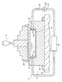
図6は、第5実施形態のワーク保持手段の断面模式図である。
第5実施形態は、第1実施形態に対して、加熱手段4が省略され、それに代わってワークを加熱および冷却する加熱・冷却手段8が付加されている点が異なる。
<Fifth Embodiment>
FIG. 6 is a schematic cross-sectional view of the work holding means of the fifth embodiment.
The fifth embodiment is different from the first embodiment in that the
加熱・冷却手段8は、ワーク保持手段3に内蔵された発熱・吸熱回路81と、発熱・吸熱回路81からの熱を受ける受熱板82とから構成される。
発熱・吸熱回路81は、テーブル32の上縁部に内蔵され、発熱および吸熱を行うペルチェ素子部811と、ペルチェ素子部811に直流電流を流す直流電源812と、直流電源812の電圧を調節する制御装置813と、ペルチェ素子部811、直流電源812および制御装置813を直列に連結した環状の導線814とによって構成された直流回路である。
ペルチェ素子部811は、テーブル32の上縁部に配置されており、並列した複数個のペルチェ素子815と、隣り合うペルチェ素子を接合する電極816とから構成される。
The heating / cooling means 8 includes a heat generation /
The heat generation /
The
ペルチェ素子815は、直方形状であり、p型とn型の2種類の半導体である。これらp型半導体とn型半導体は、それぞれの長手方向を垂直方向に向け、かつ、水平方向に沿ってp型、n型が交互に並列している。
電極816は、電導性を持つ金属板であり、全てのペルチェ素子815が直列に接続されるように、隣り合うp型半導体およびn型半導体の上端面に架設された上方電極816Aと、隣り合うp型半導体およびn型半導体の下端面に架設された下方電極816Bとがある。これにより、p型半導体とn型半導体は、交互に直列接続される。
The
The
ペルチェ素子815のp型半導体とn型半導体を電極816で直列接続し直流電流を流すと、ペルチェ素子815は、それぞれ一端で発熱現象を、他端で吸熱現象を同時に起こすという材質を持つ。よって、ここでは、各ペルチェ素子815と電極816の接合部分で発熱現象または吸熱現象が生じる。また、吸熱現象によって表面に結露が発生する場合があるので、ペルチェ素子815の表面には防水加工が施されている。
制御装置813は、外面に設置されたコンロトールパネルがテーブル32から露出しており、テーブル32の上面の温度に対応した電圧値をコントロールパネルから入力することで、直流電源812の電圧を調節することができる。
When a p-type semiconductor and an n-type semiconductor of the
In the
受熱板82は、セラミック製の長方平面板であり、ペルチェ素子部811の上下端面に接触して、つまり、ペルチェ素子815に架設された上下の電極816に接触して設けられている。これにより、ペルチェ素子部811の一端の発熱現象によって、ペルチェ素子部811の一端に設けられた一方の受熱板82は加熱され、同時に、ペルチェ素子部811の他端の吸熱現象によって、ペルチェ素子部811の他端に設けられた他方の受熱板82は冷却される。
The
放熱手段9は、ワーク保持手段3に形成され、テーブル32の下縁部に内蔵される貯水空間91と、貯水空間91に収納される温調流体92と、温調流体92を貯水空間91に通して循環させる流体移動手段93と、流体移動手段93の途中に設けられ、温調流体92を加熱および冷却する熱変換手段94とから構成される。
The heat radiating means 9 is formed in the work holding means 3, a
貯水空間91は、テーブル32に内蔵され、ペルチェ素子部811の下縁部にわずかな間を挟んで形成されている。貯水空間91の一方側壁に、流体移動手段93に接続され温調流体92が流入する流入口911と、他方側壁に、流体移動手段93に接続され温調流体92が流出する流出口912とを備えている。
The
流体移動手段93は、貯水空間91および熱変換手段94を連結し、内部に温調流体92を通す環状のパイプ931と、パイプ931の途中に設けられ温調流体92に動力を与えるポンプ932とを備えている。
熱変換手段94は、内部に流入した温調流体92を加熱および冷却して、流体移動手段93へ流出する。ワークを加熱する場合、つまり、ペルチェ素子部811の下端側が吸熱現象を生じる場合には温調流体92を加熱し、ワークを冷却する場合、つまり、ペルチェ素子部811の下端側が発熱現象を生じる場合には温調流体92を冷却する。
温調流体91は、ある程度の高温または低温においても状態変化を生じない流体であり、上記の構成によって、放熱手段9の内部を循環する。
The fluid moving means 93 connects the
The heat converting means 94 heats and cools the
The
第5実施形態の加工機械を用いたワークの加工方法は、第1実施形態で前述した加工方法に対して、加熱手段4による加熱作用が加熱・冷却手段8による加熱・冷却作用になる点、および、放熱手段9による放熱作用が加わる点を除いて同様である。よって、ここでは、加熱・冷却手段8による加熱・冷却作用、および、放熱手段9による放熱作用を説明する。
まず、ワークを加熱したい場合について説明する。ここで、ペルチェ素子815の並びは図6に示す通りとする。はじめに、加熱・冷却手段8の、発熱・吸熱回路81の制御装置813に設けられたコントロールパネルを操作して電源を入れ、発熱・吸熱回路81に矢印Aの方向へ直流電流を流す。同時に、放熱手段9のポンプ931および熱変換手段94を稼動させる。
The workpiece processing method using the processing machine of the fifth embodiment is different from the processing method described in the first embodiment in that the heating action by the heating means 4 becomes the heating / cooling action by the heating / cooling means 8, And it is the same except for the point to which the thermal radiation effect | action by the thermal radiation means 9 is added. Therefore, here, the heating / cooling action by the heating / cooling means 8 and the heat radiation action by the heat radiating means 9 will be described.
First, the case where it is desired to heat the workpiece will be described. Here, the arrangement of the
すると、ペルチェ素子815の内部に直流電流が流れる。このとき、ペルチェ素子815のp型半導体およびn型半導体の内部では、ペルチェ効果により正孔および電子が移動するが、この正孔および電子が熱エネルギーを運び、矢印Aの方向に電流を流した図6の場合、各ペルチェ素子815の上端と上方電極816Aとの接合部分で発熱現象が、同時に、各ペルチェ素子815の下端と下方電極816Bとの接合部分で吸熱現象が生じる。
Then, a direct current flows inside the
このペルチェ素子部811の上端側で生じた発熱現象によって、上方電極816Aに接触して設けられている受熱板82が加熱される。さらに、受熱板82からテーブル32の上縁部への熱伝達によってテーブル32上面およびチャック片34の温度が上昇し、テーブル32の上面に固定されたワークが加熱される。
テーブル32の上面の温度は、制御装置813によって直流電源812の電圧を制御することで調節し、また、図1のテーブル温度計測器33が表示する計測値によって確認することができる。
The
The temperature of the upper surface of the table 32 can be adjusted by controlling the voltage of the
このとき、このペルチェ素子部811の下端側では吸熱現象が生じており、この吸熱現象により受熱板82が冷却され、テーブル32の下縁部の温度が過度に低温となる危険性がある。このため、放熱手段9によって、ペルチェ素子部811の下端側による吸熱作用をある程度まで緩和する。
放熱手段9では、温調流体92が流体移動手段93によって循環している。発熱・吸熱回路81に直流電流を流すと同時に、熱変換手段94によって、熱変換手段94の内部を通過する温調流体92を加熱する。これにより、高温の温調流体92が貯水空間91に流入し、貯水空間91の内部の温度が上昇して内壁が加熱される。
At this time, an endothermic phenomenon has occurred at the lower end side of the
In the heat dissipating means 9, the
すると、貯水空間91の内壁からテーブル32への熱伝達により、テーブル32が加熱され、その結果、テーブル32の下縁部の温度低下を抑止することができる。温調流体92は、ペルチェ素子部811の下端側の吸熱作用を、加工機械に悪影響を与えない程度、かつ、作業の安全性が保たれる程度にまで緩和できる温度であればよい。
このようにして、発熱・吸熱回路81によってワークを加熱することができ、放熱手段9によって、テーブル32の下縁部の温度変化をある程度まで抑止することができる。
ワークを冷却したい場合には、発熱・吸熱回路81にAとは反対方向に電流を流し、かつ、温調流体92を熱変換手段94によって冷却しながら放熱手段9の内部を循環させる。このときの発熱・吸熱回路81および放熱手段9の作用は、上記のワークを加熱したい場合のそれらと、加熱が冷却に変更される点が異なる。
Then, the table 32 is heated by heat transfer from the inner wall of the
In this way, the work can be heated by the heat generation /
When it is desired to cool the workpiece, a current is passed through the heat generation /
第5実施形態によって、第1実施形態から得られる作用効果(1),(2)、および、第3実施形態から得られる作用効果(13),(14)に加え、次のような効果を期待することができる。
(27)ペルチェ素子部811の発熱および吸熱現象によって、ワークの加熱および冷却の両方を行うことができる。
(28)ペルチェ素子部811がワーク保持手段3に内蔵され、加熱および冷却されたテーブル32の上縁部とワークとの接触面における熱伝達によってワークを温度調整するので、ワーク保持手段3の外部からワークを加熱および冷却するのに比べ、作業を円滑、安全に行うことができる。
(29)ペルチェ素子部811がワーク保持手段3に内蔵され、加熱・冷却されたテーブル32の上縁部とワークとの接触面における熱伝達によってワークを温度調整するので、工具は加熱および冷却されにくく、熱による工具の切削性能の低下や、冷却による工具表面における結露の発生などを少なくできる。
In addition to the operational effects (1) and (2) obtained from the first embodiment and the operational effects (13) and (14) obtained from the third embodiment, the fifth embodiment provides the following effects. You can expect.
(27) Both heating and cooling of the workpiece can be performed by the heat generation and heat absorption phenomenon of the
(28) Since the
(29) Since the
(30)加熱・冷却手段8に、頻繁に交換しなければならない部材がないので、交換作業の手間を省くことができる。
(31)制御装置813を用いて直流電源812の電圧、つまり、ペルチェ素子部811から発生される発熱量を調節できるから、ワークの温度を適切に維持することができる。
(32)直流電源812の直流電流の向きを変えることによって、ペルチェ素子部811の発熱部と吸熱部の位置が切り替わるので、ワークの加熱および冷却を瞬時に切り替えることができる。
(33)放熱手段9によって、ペルチェ素子部811の下端側における余分な発熱作用および吸熱作用を緩和することができるので、テーブル32の側縁部および下縁部が加熱および冷却されすぎることはなく、ワーク保持手段3の変形、損傷を比較的少なくできる。
(30) Since there is no member in the heating / cooling means 8 that needs to be frequently replaced, the labor of replacement can be saved.
(31) Since the voltage of the
(32) Since the positions of the heat generating part and the heat absorbing part of the
(33) Since the heat generating means 9 can alleviate the excessive heat generation and heat absorption on the lower end side of the
第5実施形態では、ワークを加熱させる場合、ペルチェ素子部811の下端側の吸熱作用を放熱手段9によって緩和させたが、この吸熱作用によるテーブル32の下縁部の冷却が、テーブル32の損傷や作業の危険性を引き起こす程度ではない場合には、放熱手段9は、ペルチェ素子部811の下端の吸熱作用を緩和させる機能を備えてなくてもよい。また、第5実施形態では、温調流体92による放熱手段9を用いたが、放熱手段9は、例えば、テーブル32のペルチェ素子部811の下方に設置されたファンを備え、このファンを回転させて生じた風をテーブル32に当てることによって余分な熱を発散させる構造であってもよい。また、放熱手段9ではなく、ペルチェ素子部811の上面を除く全ての面を断熱材で被覆することで、ペルチェ素子部811の下端側とテーブル32との間の熱伝達しにくくさせてもよい。
第5実施形態の加工機械は、ワークの加熱および冷却を行えるものとしたが、ワークの冷却のみ行いたい場合は、ペルチェ素子部811を含む回路に適切な方向へ直流電流を流せばよい。
In the fifth embodiment, when the workpiece is heated, the endothermic action on the lower end side of the
The processing machine according to the fifth embodiment is capable of heating and cooling the workpiece. However, when only the workpiece is desired to be cooled, a direct current may be supplied to the circuit including the
なお、本発明は前述の実施形態に限定されるものではなく、本発明の目的を達成できる範囲での変形、改良等は本発明に含まれるものである。
例えば、第1〜第5実施形態の加工機械は、相対移動手段1が駆動することにより、工具とワークの相対移動を行うとしたが、本発明は、ワーク保持手段3が駆動するタイプ、また、工具保持手段2およびワーク保持手段3のいずれも駆動するタイプの加工機械であっても適用することができる。
It should be noted that the present invention is not limited to the above-described embodiments, and modifications, improvements, and the like within the scope that can achieve the object of the present invention are included in the present invention.
For example, the processing machines of the first to fifth embodiments perform the relative movement of the tool and the workpiece by driving the relative movement means 1, but the present invention is a type driven by the workpiece holding means 3, The present invention can also be applied to a processing machine that drives both the tool holding means 2 and the work holding means 3.
また、第1〜第5実施形態では、相対移動手段1の駆動は、制御手段に入力された信号によって制御されるとしたが、本発明では、三軸方向の駆動制御は、相対移動手段1にレバーやハンドルなどを備えて手動で行ってもよい。
また、第1および第4実施形態では、断熱材42,75によってテーブル32の側縁部および下縁部の温度変化が少なくなるようにしたが、例えば、テーブル32の下縁部に放熱手段を設け、加熱手段4または加熱・冷却手段7から発生される余分な発熱および吸熱を緩和させてもよい。放熱手段には、温調流体を用いる方法、ファンの風によって熱を発散させる方法などが考えられる。
また、第1、第2、第4、第5実施形態では、ワークの温度調整を行うには、各温度調節手段(加熱手段4,5、加熱・冷却手段7,8)を操作するとしたが、本発明では、テーブル32の上面の設定温度を入力すると、テーブル32の上面がその設定温度で一定に保たれるように、各温度調節手段の制御を自動的に行う温度制御手段(図示省略)を付加しても良い。このような構成によれば、温度調整のために各温度調節手段を細かく操作する手間を省くことができる。
In the first to fifth embodiments, the driving of the relative movement unit 1 is controlled by a signal input to the control unit. However, in the present invention, the driving control in the triaxial direction is performed by the relative movement unit 1. It may be done manually with a lever or handle.
In the first and fourth embodiments, the temperature change of the side edge portion and the lower edge portion of the table 32 is reduced by the
In the first, second, fourth, and fifth embodiments, each temperature adjusting means (heating means 4 and 5 and heating / cooling means 7 and 8) is operated to adjust the temperature of the workpiece. In the present invention, when the set temperature of the upper surface of the table 32 is input, the temperature control means (not shown) automatically controls each temperature adjusting means so that the upper surface of the table 32 is kept constant at the set temperature. ) May be added. According to such a configuration, it is possible to save the trouble of finely operating each temperature adjusting means for temperature adjustment.
本発明は、加工機械に利用することができる。 The present invention can be used for a processing machine.
1…相対移動手段,2…工具保持手段,3…ワーク保持手段,4…加熱手段,41…電気熱変換手段,5…加熱手段,51…磁場発生手段,6…冷却手段,61…冷媒収納空間,62…ドライアイス,7…加熱・冷却手段,71…流体収納空間,72…温調流体,73…流体移動手段,74…熱変換手段,8…加熱・冷却手段81…発熱・吸熱回路,815…ペルチェ素子 DESCRIPTION OF SYMBOLS 1 ... Relative movement means, 2 ... Tool holding means, 3 ... Work holding means, 4 ... Heating means, 41 ... Electrothermal conversion means, 5 ... Heating means, 51 ... Magnetic field generating means, 6 ... Cooling means, 61 ... Refrigerant storage Space, 62 ... Dry ice, 7 ... Heating / cooling means, 71 ... Fluid storage space, 72 ... Temperature control fluid, 73 ... Fluid moving means, 74 ... Heat conversion means, 8 ... Heating / cooling means 81 ... Heat generation / heat absorption circuit 815: Peltier element
Claims (3)
前記テーブルに内蔵され前記テーブルの上面を加熱する加熱手段を備え、
前記加熱手段は、電気エネルギーを熱エネルギーに変換する電気熱変換手段によって構成されていることを特徴とする加工機械。 In a processing machine having a work holding means having a table for placing a work on an upper surface, a tool holding means for holding a tool for processing a work, and a relative movement means for relatively moving the work holding means and the tool holding means ,
A heating means built in the table for heating the upper surface of the table;
The processing machine, wherein the heating means is constituted by electrothermal conversion means for converting electrical energy into thermal energy.
前記テーブルに内蔵され前記テーブルの上面を冷却する冷却手段を備え、
前記冷却手段は、ペルチェ素子を含む回路によって構成されていることを特徴とする加工機械。 In a processing machine having a work holding means having a table for placing a work on an upper surface, a tool holding means for holding a tool for processing a work, and a relative movement means for relatively moving the work holding means and the tool holding means ,
A cooling means built in the table for cooling the upper surface of the table ;
It said cooling means, the processing machine, characterized in that it is constituted by a circuit including a Peltier element.
前記テーブルに内蔵され前記テーブルの上面を加熱する加熱手段と前記テーブルに内蔵され前記テーブルの上面を冷却する冷却手段とを備え、
前記加熱手段および前記冷却手段は、ペルチェ素子を含む発熱・吸熱回路によって構成されていることを特徴とする加工機械。 In a processing machine having a work holding means having a table for placing a work on an upper surface, a tool holding means for holding a tool for processing a work, and a relative movement means for relatively moving the work holding means and the tool holding means ,
A heating means built in the table for heating the upper surface of the table and a cooling means built in the table for cooling the upper surface of the table ;
It said heating means and said cooling means, the processing machine, characterized in that it is constituted by the exothermic endothermic circuit including a Peltier element.
Priority Applications (1)
| Application Number | Priority Date | Filing Date | Title |
|---|---|---|---|
| JP2004282409A JP4783000B2 (en) | 2004-09-28 | 2004-09-28 | Processing machine |
Applications Claiming Priority (1)
| Application Number | Priority Date | Filing Date | Title |
|---|---|---|---|
| JP2004282409A JP4783000B2 (en) | 2004-09-28 | 2004-09-28 | Processing machine |
Publications (2)
| Publication Number | Publication Date |
|---|---|
| JP2006095618A JP2006095618A (en) | 2006-04-13 |
| JP4783000B2 true JP4783000B2 (en) | 2011-09-28 |
Family
ID=36235921
Family Applications (1)
| Application Number | Title | Priority Date | Filing Date |
|---|---|---|---|
| JP2004282409A Expired - Fee Related JP4783000B2 (en) | 2004-09-28 | 2004-09-28 | Processing machine |
Country Status (1)
| Country | Link |
|---|---|
| JP (1) | JP4783000B2 (en) |
Families Citing this family (3)
| Publication number | Priority date | Publication date | Assignee | Title |
|---|---|---|---|---|
| US7568275B2 (en) * | 2006-11-13 | 2009-08-04 | Jensen Robert M | Apparatus, systems and methods for work piece isothermal dry machining and assembly fixtures |
| JP6259348B2 (en) * | 2014-04-04 | 2018-01-10 | 株式会社 エマージー | Processing tool cooling device and processing method |
| JP6773482B2 (en) * | 2016-08-17 | 2020-10-21 | 株式会社ディスコ | How to idle the grinding machine |
Family Cites Families (6)
| Publication number | Priority date | Publication date | Assignee | Title |
|---|---|---|---|---|
| JPS59192401A (en) * | 1983-04-11 | 1984-10-31 | Sumitomo Electric Ind Ltd | Machining method of niti alloy carrying form memory effect |
| US4535216A (en) * | 1983-10-14 | 1985-08-13 | Rockwell International Corporation | Metal-working tool using electrical heating |
| JPS63288602A (en) * | 1987-05-22 | 1988-11-25 | Nippon Plast Co Ltd | Burr remover for molded product |
| JPH0717193A (en) * | 1993-06-30 | 1995-01-20 | Roland D G Kk | Control device of carving machine |
| JP2002355727A (en) * | 2001-05-30 | 2002-12-10 | Daishowa Seiki Co Ltd | Shrinkage-fitted tool holder |
| JP2004066437A (en) * | 2002-08-09 | 2004-03-04 | Makino Milling Mach Co Ltd | Machine tool capable of preventing thermal deformation |
-
2004
- 2004-09-28 JP JP2004282409A patent/JP4783000B2/en not_active Expired - Fee Related
Also Published As
| Publication number | Publication date |
|---|---|
| JP2006095618A (en) | 2006-04-13 |
Similar Documents
| Publication | Publication Date | Title |
|---|---|---|
| KR20150097426A (en) | A machine tool having functional components that produce heat during the operation | |
| JP5792827B2 (en) | Guidance system for machine tools | |
| JP4783000B2 (en) | Processing machine | |
| JP4827959B2 (en) | Machine tool feed shaft cooling system | |
| JPH10230435A (en) | Heating and cooling method using electronic cooling element, heating and cooling device therewith, and attitude control device for machine tool | |
| JP2555331B2 (en) | Precision processing equipment | |
| JP2010053919A (en) | Nut | |
| JP2008119797A (en) | Surface grinding machine | |
| KR101830506B1 (en) | Spot welding test apparatus | |
| JP2004042144A (en) | Processing device and processing method | |
| JP6307591B2 (en) | Atmospheric pressure plasma generator | |
| JP2002103102A (en) | Working apparatus and working method | |
| WO2001089751A1 (en) | Electric discharge machine driven by linear motor | |
| US20210121953A1 (en) | Lamination molding apparatus | |
| JP2005262379A (en) | Machine tool | |
| JP6401045B2 (en) | Work processing machine | |
| JP2005288591A (en) | Mobile cooling device and workpiece fixation device using it | |
| CN108161603B (en) | Magnetic field auxiliary plane grinding equipment | |
| JP6698106B2 (en) | Coolant device for machine tools | |
| JP3671214B2 (en) | Temperature control method and apparatus for machine tool | |
| JP2719759B2 (en) | Freezing chuck and its cooling device | |
| JP4568834B2 (en) | Temperature control method and apparatus for machine tool | |
| CN112639379B (en) | Fluid temperature regulating device | |
| CN116551149A (en) | Friction stir welding equipment, heat dissipation and position correction method | |
| CN220427101U (en) | Electric welding equipment with auxiliary positioning electric welding gun |
Legal Events
| Date | Code | Title | Description |
|---|---|---|---|
| A621 | Written request for application examination |
Free format text: JAPANESE INTERMEDIATE CODE: A621 Effective date: 20070604 |
|
| RD02 | Notification of acceptance of power of attorney |
Free format text: JAPANESE INTERMEDIATE CODE: A7422 Effective date: 20070809 |
|
| A977 | Report on retrieval |
Free format text: JAPANESE INTERMEDIATE CODE: A971007 Effective date: 20100416 |
|
| A131 | Notification of reasons for refusal |
Free format text: JAPANESE INTERMEDIATE CODE: A131 Effective date: 20100601 |
|
| A521 | Request for written amendment filed |
Free format text: JAPANESE INTERMEDIATE CODE: A523 Effective date: 20100728 |
|
| A131 | Notification of reasons for refusal |
Free format text: JAPANESE INTERMEDIATE CODE: A131 Effective date: 20110329 |
|
| A521 | Request for written amendment filed |
Free format text: JAPANESE INTERMEDIATE CODE: A523 Effective date: 20110525 |
|
| TRDD | Decision of grant or rejection written | ||
| A01 | Written decision to grant a patent or to grant a registration (utility model) |
Free format text: JAPANESE INTERMEDIATE CODE: A01 Effective date: 20110705 |
|
| A01 | Written decision to grant a patent or to grant a registration (utility model) |
Free format text: JAPANESE INTERMEDIATE CODE: A01 |
|
| A61 | First payment of annual fees (during grant procedure) |
Free format text: JAPANESE INTERMEDIATE CODE: A61 Effective date: 20110708 |
|
| FPAY | Renewal fee payment (event date is renewal date of database) |
Free format text: PAYMENT UNTIL: 20140715 Year of fee payment: 3 |
|
| R150 | Certificate of patent or registration of utility model |
Ref document number: 4783000 Country of ref document: JP Free format text: JAPANESE INTERMEDIATE CODE: R150 Free format text: JAPANESE INTERMEDIATE CODE: R150 |
|
| S533 | Written request for registration of change of name |
Free format text: JAPANESE INTERMEDIATE CODE: R313533 |
|
| R350 | Written notification of registration of transfer |
Free format text: JAPANESE INTERMEDIATE CODE: R350 |
|
| LAPS | Cancellation because of no payment of annual fees |