JP4781609B2 - Fan unit - Google Patents
Fan unit Download PDFInfo
- Publication number
- JP4781609B2 JP4781609B2 JP2002567751A JP2002567751A JP4781609B2 JP 4781609 B2 JP4781609 B2 JP 4781609B2 JP 2002567751 A JP2002567751 A JP 2002567751A JP 2002567751 A JP2002567751 A JP 2002567751A JP 4781609 B2 JP4781609 B2 JP 4781609B2
- Authority
- JP
- Japan
- Prior art keywords
- air flow
- fan
- fan unit
- guide
- baffle
- Prior art date
- Legal status (The legal status is an assumption and is not a legal conclusion. Google has not performed a legal analysis and makes no representation as to the accuracy of the status listed.)
- Expired - Fee Related
Links
Images


Landscapes
- Structures Of Non-Positive Displacement Pumps (AREA)
Description
この発明は、ファンユニットに関する。 The present invention relates to a fan unit.
近代の生産および/または試験設備においては出力対象の品質を保証するために空気中の多数の粒子を制御することが普通である。それが、ウエハダイスであろうと、コンパクトディスクであろうと、メモリーディスクダイスであろうと、クリーンルーム内の粒子の含有量を受け入れ可能な水準に保つためばかりでなく、空気をクリーンルーム内の作業員達のための快適な作業環境を維持するために循環させるためにも、有効なファンフィルターユニットが必要である。 In modern production and / or test facilities, it is common to control a large number of particles in the air to ensure the quality of the output object. Whether it is a wafer die, a compact disc, or a memory disc die, not only keep the content of particles in the clean room at an acceptable level, but also air for the workers in the clean room. An effective fan filter unit is also required for circulation in order to maintain a comfortable working environment.
しかしながら、そのような強力なファンフィルターユニットは、過剰な騒音を発生する。騒音を減らすために、空気の流れに接する導管に沿って、ファンフィルターユニットまで、または、その内部まで絶縁部材を裏打ちすることが知られている。しかしながら、時間の経過とともに、粒子やファイバーが表面から剥離してクリーンルームの設備を汚染する。 However, such powerful fan filter units generate excessive noise. In order to reduce noise, it is known to line the insulating member along a conduit in contact with the air flow to the fan filter unit or to the interior thereof. However, over time, particles and fibers can flake off the surface and contaminate clean room equipment.
ファンフィルターユニットに関連する問題は、複層のウエハを組み立てるプラントのような限られた空間またはエンクロージャー内においては特に悪化する。この発明は、限られた空間によって、天井の高さを3メートルよりも小さく想定する。低い天井は、ファンフィルターユニットからの騒音を特に強調する原因をなす。 The problems associated with fan filter units are particularly exacerbated in confined spaces or enclosures such as plants that assemble multi-layer wafers. This invention assumes that the ceiling height is less than 3 meters due to limited space. The low ceiling causes a special emphasis on the noise from the fan filter unit.
これまでに、ファンフィルターユニットからの騒音を最小化する1つの装置が、下記の特許文献1に当出願人によって示唆されている。また、ファンフィルターユニットからの騒音を最小化する別の装置は、当出願人による下記の特許文献2に記載されている。
So far, one apparatus for minimizing noise from the fan filter unit has been suggested by the applicant in the following
この発明は、ユニットを通る汚染物を増加させることなく騒音を減少するファンユニットを見出したものであり、前記ファンユニットは製造が容易で高いパワー効率を有する。 The present invention has found a fan unit that reduces noise without increasing contaminants through the unit, the fan unit being easy to manufacture and having high power efficiency.
したがって、この発明は、1つの空気の流れの面内において空気を複数の方向に発射する構造のファンブロワーであって、
空気の流れの面内において、ファンブロワーの第1の側に配置された第1および第2の案内表面を有し、
第1および第2の案内表面は、一緒になって、第1の空気流チャンネルに至る第1の空気流の通路の径方向外側の少なくとも一部の限界を規定し、
空気の流れの面内においてファンブロワーの第2の、反対の側に配置された第3および第4の案内表面を有し、第3および第4の案内表面は、一緒になって、第2の空気流チャンネルに至る第2の空気流通路の径方向外側の少なくとも一部の限界を規定し、
第1、第2、第3、および、第4の案内表面は、別体の案内手段に装着されているファンブロワーを提供する。
Accordingly, the present invention is a fan blower having a structure for emitting air in a plurality of directions in the plane of one air flow,
In the plane of air flow, having first and second guide surfaces arranged on the first side of the fan blower;
The first and second guide surfaces together define at least a partial limit radially outward of the passage of the first air flow leading to the first air flow channel;
A third and fourth guide surface disposed on the second, opposite side of the fan blower in the plane of air flow, wherein the third and fourth guide surfaces together form a second Defining at least a portion of the radial outside of the second airflow passage leading to the second airflow channel,
The first, second, third and fourth guide surfaces provide a fan blower mounted on a separate guide means.
各空気流通路用の案内を一対の別体の案内表面から構築することによって、ファンユニットの構造が極めて簡単になる。比較的小さい多数のパーツから広範な構造体が構築可能である。
各案内表面は、任意の適当な形状に製造することが可能である。それは湾曲状でも直線状でも差し支えない。第1および第2の空気流通路は、案内表面によって、径方向外側に、そして、ファンブロワーの周辺部によって径方向内側に規定される。空気流の通路は、任意の適当な形態であってよい。それらは、直線状であって差し支えないが、好ましくは、空気流通路が湾曲される。空気流の通路は、ファンブロワーの回転方向に角度をなして拡散することが好ましい。
By constructing the guide for each airflow passage from a pair of separate guide surfaces, the structure of the fan unit is greatly simplified. A wide range of structures can be constructed from many relatively small parts.
Each guide surface can be manufactured in any suitable shape. It can be curved or straight. The first and second airflow passages are defined radially outward by the guide surface and radially inward by the periphery of the fan blower. The air flow passage may be in any suitable form. They can be straight, but preferably the air flow passage is curved. The air flow passage is preferably diffused at an angle in the direction of rotation of the fan blower.
第1および第2の空気流の通路は、それぞれの案内の対のみによって径方向外側に規定されることができる。その代わりに、空気流の別の部分を規定する追加的な案内体があってもよい。
特に好ましい具体例においては、ファンユニットは、ファンブロワーの第1の側に第1の壁手段を有し、第1の案内表面は、第1の部位において第1の壁手段に接しており、第2の案内表面は、第1の部位から離間した第2の部位において第1の壁手段に接しているので、第1および第2の部位の間の第1の壁手段の部分は、別の案内表面を有効に規定しており、ファンユニットは、ファンブロワーの第2の側に第2の壁手段を有し、第3の案内表面は、第1の部位において第2の壁手段に接し、第4の案内表面は、第1の部位から離間した第2の部位において第2の壁手段に接しているので、第1および第2の部位の間の第2の壁手段の部分は、別の案内表面を有効に規定している
少なくとも4つの案内手段が提供され、第1の案内手段は、第1の案内表面を含み、第2の案内手段は第2の案内表面を含み、第3の案内手段は、第3の案内表面を含み、第4の案内手段は、第4の案内表面を含む。
The first and second airflow passages can be defined radially outward by only the respective guide pairs. Instead, there may be an additional guide that defines another part of the air flow.
In a particularly preferred embodiment, the fan unit has first wall means on the first side of the fan blower, the first guiding surface is in contact with the first wall means at the first location, Since the second guide surface is in contact with the first wall means at the second part spaced from the first part, the portion of the first wall means between the first and second parts is different. The fan unit has a second wall means on the second side of the fan blower, and the third guide surface is a second wall means at the first location. The fourth guide surface is in contact with the second wall means at the second part spaced from the first part, so that the portion of the second wall means between the first and second parts is At least four guiding means are provided, effectively defining another guiding surface, the first guiding means being The first guiding surface, the second guiding means comprises a second guiding surface, the third guiding means comprises a third guiding surface, and the fourth guiding means comprises a fourth guiding surface. including.
各案内手段が、1つの追加的な案内表面を有し、異なる1つの面で第1、第2、第3および第4の案内表面に面することが好ましい。案内手段の追加的な案内面は、空気流の通路が空気流のチャンネルに進入する部位において、流れの滑らかな通路の提供を支援する。 Each guiding means preferably has one additional guiding surface and faces the first, second, third and fourth guiding surfaces in one different plane. The additional guide surface of the guide means assists in providing a smooth flow path at the site where the air flow path enters the air flow channel.
特に好ましい具体例においては、少なくとも第1と第3の案内手段が互いに同一であり、好ましくは全案内手段が互いに同一である。このことは、ただ1つのタイプの案内手段を製造すれば済むので製造と構造を特に簡単にする。
この案内表面、および、各案内手段の現行の追加的な案内表面は、任意の形態を取ることができ、好ましくは直線状か湾曲状である。案内表面から追加案内表面に至る遷移域は点によって規定される。しかしながら、それは、空気の流れを改善し、騒音を減少するために滑らかな湾曲遷移表面によって規定されることが好ましい。
In a particularly preferred embodiment, at least the first and third guiding means are identical to each other, preferably all guiding means are identical to each other. This makes manufacturing and construction particularly simple since only one type of guiding means needs to be manufactured.
This guide surface, and the current additional guide surface of each guide means, can take any form, and is preferably straight or curved. The transition region from the guide surface to the additional guide surface is defined by a point. However, it is preferably defined by a smooth curved transition surface to improve air flow and reduce noise.
好ましくは、第1の案内表面が、第2の案内表面よりもファンブロワーの軸に近接している。同様に、第3の案内表面は、第4の案内表面よりもファンブロワーの軸に近いことが好ましい。このように、拡散状の流れの通路が提供される。好ましくは、第1および第3の案内表面が、ファンブロワーの軸から等距離に配置され、第4および第2の案内表面が互いにファンブロワーの軸から等距離に配置される。このようにして、合理的で対称な構造体が達成される。 Preferably, the first guide surface is closer to the fan blower axis than the second guide surface. Similarly, the third guide surface is preferably closer to the fan blower axis than the fourth guide surface. In this way, a diffuse flow path is provided. Preferably, the first and third guide surfaces are arranged equidistant from the fan blower axis, and the fourth and second guide surfaces are arranged equidistant from the fan blower axis. In this way a rational and symmetric structure is achieved.
この構造体においては、ファンブロワーは、それが機能するために正確な方向に回転しなければならない。特に、ファンブロワーは、空気流の通路のはばを増す方向に回転しなければならない。
好ましくは、案内手段は同一であり、各案内手段は遷移域を通る鏡面を中心に対称であるから、それは案内表面と、追加表面を持ち、追加表面は実質的に、案内表面と同一である。案内手段は、相対的に容易に再配置できるので、案内表面のこの配置はふぁんを反対の方向に適切に回転させることができる。特に、案内表面の配置は、ファンが第1の方向に回転する案内面の配置、鏡面がファンブロワーの軸を通る案内面の配置の鏡像でなければならない。
In this structure, the fan blower must rotate in the correct direction for it to function. In particular, the fan blower must rotate in the direction of increasing the airflow passage.
Preferably, the guiding means are identical and each guiding means is symmetrical about a mirror plane passing through the transition zone, so it has a guiding surface and an additional surface, the additional surface being substantially identical to the guiding surface. . Since the guiding means can be repositioned relatively easily, this arrangement of the guiding surface can properly rotate the fan in the opposite direction. In particular, the arrangement of the guide surfaces must be a mirror image of the arrangement of the guide surfaces in which the fan rotates in the first direction, the arrangement of the guide surfaces with mirror surfaces passing through the axis of the fan blower.
好ましくは、第1および第2の空気流チャンネルはそれぞれ、空気流を転向させるために空気流の方向に対して或る角度をなして設けられた第1のバッフルに至る。空気流は下方に向けられることが好ましい。
垂直方向が、ファンから射出された空気面に対して直角をなす方向とされる。
Preferably, each of the first and second air flow channels leads to a first baffle provided at an angle to the direction of air flow to divert the air flow. The air flow is preferably directed downward.
The vertical direction is a direction perpendicular to the air surface emitted from the fan.
好ましくは、第1および第2の空気流チャンネルは、それぞれ、空気流を更に転向させるために第1のバッフルから到達する空気流の方向に対して或る角度をなして設けられる第2のバッフルを有する。適切には、第2のバッフルが、第1のバッフルの下に装着される。第1および第2のバッフルは、一緒になって、各空気流を最小の乱流を伴って90度〜180度の範囲の角度だけ転向させる。 Preferably, the first and second air flow channels are each a second baffle provided at an angle with respect to the direction of air flow arriving from the first baffle to further divert the air flow. Have Suitably, a second baffle is mounted under the first baffle. The first and second baffles together turn each air flow by an angle in the range of 90 degrees to 180 degrees with minimal turbulence.
第1および第2のバッフルは、好ましくは、バッフル同士の間の距離がファンから離れるにつれて直線方向に減少するように、互いに対し傾斜される。これらのバッフルは、空気が案内を離れるにしたがって、空気が、第1のバッフルによって第2のバッフルに向かって転向されるように配置され、第2のバッフルは、空気を1つの導出口から外に向けるように配置されている。 The first and second baffles are preferably tilted relative to each other such that the distance between the baffles decreases in a linear direction as they move away from the fan. These baffles are arranged such that as the air leaves the guide, the air is diverted by the first baffle toward the second baffle, and the second baffle removes the air from one outlet. It is arranged to point to.
好ましくは、第1のバッフルまたは第2のバッフルが、最も好ましくは、これらの両方が、音の吸収を改善するために穿孔された材料を有する。
好ましくは、第1のバッフルが、空気流の面に対して40度〜60度、好ましくは45度、の角度をなして設けられる。好ましくは、第2のバッフルが、ファンから空気流の面に対して5度〜10度、好ましくは10度の角度で配置される。
Preferably the first baffle or the second baffle, most preferably both of them have perforated material to improve sound absorption.
Preferably, the first baffle is provided at an angle of 40 degrees to 60 degrees, preferably 45 degrees with respect to the plane of air flow. Preferably, the second baffle is arranged at an angle of 5 degrees to 10 degrees, preferably 10 degrees with respect to the air flow plane from the fan.
好ましくは、第1および第2の空気流チャンネルが、それぞれ、空気流を転向させるための最終のバッフルを備える。好ましくは、最終のバッフルが、空気流を下方に転向させる。好ましくは、最終のバッフルは、ファンブロワーの真下に装着される。好ましくは、第1および第2の空気流チャンネルが、互いに接してほぼV字状の構造を形成する。 Preferably, the first and second air flow channels each comprise a final baffle for diverting the air flow. Preferably, the final baffle turns the air flow downward. Preferably, the final baffle is mounted directly under the fan blower. Preferably, the first and second air flow channels contact each other to form a generally V-shaped structure.
好ましくは、ファンユニットがハウジングを有する。
好ましくは、ファンブロワーと案内表面が、ベースプレートに配置される。
好ましくは、ユニットが更に、空気をファンに引き込むための導入口を備えるベースプレートに連結された上部ハウジングを有しており、ファンと案内は、上部ハウジングとベースプレートの間に配置される。好ましくは、ハウジングが、側部セクションを有し、各空気流チャンネルと連通する空気導出口が、ベースと側部セクションと、上部ハウジングの間の間隙部によって形成される。好ましくは、側部セクションが上に説明したように壁手段を備える。この側部セクションは、上部ハウジングと一体であることができる。
Preferably, the fan unit has a housing.
Preferably, the fan blower and the guide surface are arranged on the base plate.
Preferably, the unit further comprises an upper housing connected to the base plate with an inlet for drawing air into the fan, the fan and the guide being arranged between the upper housing and the base plate. Preferably, the housing has side sections and an air outlet communicating with each air flow channel is formed by a gap between the base and side sections and the upper housing. Preferably, the side section comprises wall means as described above. This side section can be integral with the upper housing.
好ましくは、別のバッフルが、側部セクションとベースプレートの間の間隙部に少なくとも部分的に配置されている。
上記の構造においては、好ましくは、ベースプレートが、ベースプレートと上部ハウジングの上表面との間の距離が、側部セクションがその分だけハウジングの上面から突出する距離よりも小さいように、ハウジングに対して配置される。側部セクションとベースプレートの間にも間隙部があって、ファンユニットの導出口を形成している。ハウジングの側部セクションとベースプレートの間の間隙部は、理想的には、少なくとも下部バッフルをこの間隙部内に収容するために充分に大きくなければならない。
Preferably, another baffle is at least partially disposed in the gap between the side section and the base plate.
In the above structure, preferably the base plate is relative to the housing such that the distance between the base plate and the upper surface of the upper housing is less than the distance that the side section projects from the upper surface of the housing. Be placed. There is also a gap between the side section and the base plate to form a fan unit outlet. The gap between the side section of the housing and the base plate should ideally be large enough to accommodate at least the lower baffle within this gap.
好ましくは、ファンユニットがフィルターを有する。
案内の形態は、ファンユニットから騒音を減少する。また、案内の形態は、ユニット内を循環する空気の速度を速める。したがって、下部のパワーがファンを同じ循環速度を達成するための駆動に使用されるので、より効率的なファンユニットが製造されることができる。
Preferably, the fan unit has a filter.
The form of guidance reduces noise from the fan unit. Further, the form of guidance increases the speed of air circulating in the unit. Therefore, a more efficient fan unit can be manufactured because the lower power is used to drive the fan to achieve the same circulation speed.
この発明のファンユニットは、第1にクリーンルームにおける使用を目的としている。したがって、このユニットは、フィルターを有することが好ましい。一般に、このフィルターは、ユニットのベースプレートの下に配置される。
この発明の案内および/またはバッフルは、好ましくは、硬質の材料、より好ましくは金属から製造される。案内および/またはバッフルは、穿孔されても良い。
The fan unit of the present invention is primarily intended for use in a clean room. Therefore, this unit preferably has a filter. Generally, this filter is placed under the base plate of the unit.
The guides and / or baffles of the present invention are preferably made from a hard material, more preferably a metal. The guide and / or baffle may be perforated.
この発明のファンユニットは、ユニットを通過する空気流と接触する従来の音響絶縁材料を備えていない。音響絶縁材料は、ファンユニットに含まれることができるが、バッフル、または、壁手段のような硬質の構造体によって別体とされることが好ましい。 The fan unit of the present invention does not include a conventional acoustic insulation material that contacts the air flow through the unit. The acoustic insulation material can be included in the fan unit, but is preferably separated by a hard structure such as a baffle or wall means.
この発明は、従来技術のエネルギーの利用に較べて相当に大きい利点を提供する。 The present invention offers significant advantages over prior art energy utilization.
この発明は、下記の非限定的な具体例を参照しつつ説明される。
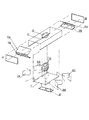
図1は、ファンフィルターユニットの組み立て分解図を示す。説明を明瞭にするために、フィルターは図示しない。回転可能なファンブロワー12がベースプレート14に配置されている。ファンブロワー12のための装着プレート20が、ベースプレート14の反対側においてファンブロワー12に設けられている。ファンブロワー12は、ベースプレート14、上部ハウジング16、および、端部セクション22から形成されるハウジング内に配置されている。上部ハウジング16は、使用時に、空気導入口がファンブロワー12の上方に位置するように、その中心に位置する空気の導入口18を有する。ファンブロワー12は、従来タイプのブロワーである。それは、ベースプレート14の反対側においてファンブロワー12に配置されている(図示しない)モータによって回転される構造である。ファンブロワーが回転するとともに、空気が導入口18を経て引き込まれ、ファンブロワーの回転方向に対して接線の方向に向かって排出される。
The invention will now be described with reference to the following non-limiting specific examples.
FIG. 1 shows an exploded view of the fan filter unit. For clarity of explanation, the filter is not shown. A
ファンブロワーは、また、一方の側に第1および第2の案内手段24Aと24B、および、他方の側に第3、第4の案内手段24C、24Dを備える。案内手段の形状は、図3に関連して以下に別に説明されるであろう。
上部バッフル26Aおよび26B、および、下部バッフル28Aおよび28Bは、これらのバッフルがファンブロワー12、案内手段24A、24B、24C、24D、および端部セクション22の間に位置するように、ユニットの両端部に設けられる。
The fan blower also includes first and second guiding means 24A and 24B on one side, and third and fourth guiding means 24C and 24D on the other side. The shape of the guiding means will be described separately below in connection with FIG.
The
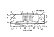
図2は、図1のファンフィルターの内部における空気流の方向を示す。前に説明した通り、空気はブロワー12の回転によって、導入口18を通って引き込まれる。ファンブロワー12は、ベースプレート14上に配置される。ファンブロワーの回転は、空気をファンブロワーからバッフル26A、26B、28A、28Bに向かうように強制する。バッフルの配置方向は、空気をベースプレートに配置されたブロワーから遠ざかる方向からベースプレート14の直下に配置された導出口19から出る方向へと反転させる。空気は、次いで、導出口19の真下に配置されたフィルター32を通過して移動する。
FIG. 2 shows the direction of air flow inside the fan filter of FIG. As previously described, air is drawn through the
図3は、図1、図2の組み立てられたファンフィルターユニットの平面図を示す。ファンブロワー12は、案内手段24A、24B、24C、および、24Dの間の空間に配置されている。ファンフィルターユニットの一方の側には、第1の案内表面27Aと、第2の案内表面27Bが存在する。これらの案内表面は、壁25Aの一部に沿って、狭窄部30を介して、上部バッフル26Bに至る空気流の通路の径方向外側限界を規定する。第3の案内表面27Cと第4の案内表面27Dは、ファンブロワーの他方の側に配置されており、これらの間の壁25Bの一部とともに、狭窄部31を介して上部バッフル26Aに至る空気流の第2の通路の径方向外側限界を規定する。各案内手段は、追加的な案内表面32A、32B、32C、および、32Dをそれぞれ有することがわかる。追加的な案内表面32Aと32Cは、これらの間に、狭窄部31から導かれる拡散する流れの通路を規定することがわかる。追加的な案内表面32Bと32Dは、これらの間に、狭窄部30から導かれる拡散する流れの通路を規定する。
FIG. 3 shows a plan view of the assembled fan filter unit of FIGS. The
案内手段24A、24B、24Cおよび24Dは、他方の案内手段と形状が同一である。各案内手段は、滑らかな湾曲案内表面と滑らかな追加的な湾曲案内表面とを備えており、これらの間には、滑らかに湾曲する遷移ゾーン33を備えている。この滑らかな湾曲遷移ゾーンは、乱流を減少し空気流の速度を改善するために設けられる。滑らかな湾曲部分33Aの中心からファンブロワーの中心線までの距離aは、ファンブロワーの中心線から遷移部分33Bの中心線までの距離bよりも小さいことも図3から明らかである。 The guiding means 24A, 24B, 24C and 24D have the same shape as the other guiding means. Each guiding means comprises a smooth curved guiding surface and a smooth additional curved guiding surface, with a smoothly curved transition zone 33 between them. This smooth curved transition zone is provided to reduce turbulence and improve air flow velocity. It is also clear from FIG. 3 that the distance a from the center of the smooth curved portion 33A to the center line of the fan blower is smaller than the distance b from the center line of the fan blower to the center line of the transition portion 33B.
同様に、他方の側においては、ファンブロワーの中心線から遷移部分33Dの中心までの距離dが、ファンブロワーの中心線から遷移部分33Cの中心までの距離cよりも小さい。このように、同一形状の案内手段を備えることによって、ファンブロワーの周囲を囲んで拡散する空気流の通路が提供される。 Similarly, on the other side, the distance d from the center line of the fan blower to the center of the transition portion 33D is smaller than the distance c from the center line of the fan blower to the center of the transition portion 33C. Thus, by providing the guide means having the same shape, a passage of air flow that diffuses around the fan blower is provided.
案内24A、24B、24Cおよび24Dは、(点線の円で示される)ファンブロワー12からの放出空気を受け入れて、空気流を最小量の乱流を伴ってバッフル26、28に向かって案内する。この図は上面図なので、下部のバッフル28は明確には示されていない。
上部のバッフル26は、ブロワー12から放射される空気の平面に対して約45度の角度で配置されており、空気を案内24から拡散する。下部バッフル28は、空気流の面に対して約10度の角度で配置されており、空気流をベースプレート14の下方に再指向する。
The upper baffle 26 is disposed at an angle of about 45 degrees with respect to the plane of air emitted from the
図4、5および6は、ファンユニットからの2つの結果を示す。図5は、ファンユニット内の15個所異なる部位において行われた測定値を平均した空気速度のプロットを示す。ファンユニット内の15箇所の配置は図4に示されている。同様に、図6は、ファンブロワーの回転周波数に対して、前記と同じ15箇所の異なる部位において測定した騒音レベルの平均値のプロットを示す。 4, 5 and 6 show two results from the fan unit. FIG. 5 shows a plot of air velocity averaged over measurements taken at 15 different locations within the fan unit. The arrangement of 15 locations in the fan unit is shown in FIG. Similarly, FIG. 6 shows a plot of the average value of the noise level measured at the same 15 different locations as described above with respect to the rotational frequency of the fan blower.
この騒音レベルは、ファンから1メートルだけ離れた距離において測定されたデシベル値である。
空気案内とバッフルとが存在するときの方が遥かに卓越した結果が提供されることがわかる。したがって、この発明は、ファンに対する同一量の駆動パワーで、増大した空気循環作用をもたらす大きな空気速度を可能にする。それゆえに、この発明は、従来技術のエネルギーの利用に較べて相当に大きい利点を提供する。
This noise level is a decibel value measured at a distance of 1 meter from the fan.
It can be seen that far superior results are provided when air guidance and baffles are present. Thus, the present invention allows large air speeds that provide increased air circulation with the same amount of drive power to the fan. Therefore, the present invention provides significant advantages over prior art energy utilization.
Claims (10)
1つの空気の流れの面内において空気を複数の方向に発射する構造のファンブロワーと、
第1、第2、第3、第4の案内表面をそれぞれ有する第1、第2、第3、第4の案内手段とを備え、
前記第1および第2の案内表面は、前記空気の流れの面内において、前記ファンブロワーの第1の側に配置されるとともに、前記第1および第2の案内表面は、一緒になって、第1の空気流チャンネルをもたらす第1の空気流の通路の径方向外側の少なくとも一部の限界を画定し、
前記第3および第4の案内表面は、前記空気の流れの面内において、前記ファンブロワーの反対側の第2の側に配置されるとともに、前記第3および第4の案内表面は、一緒になって、第2の空気流チャンネルをもたらす第2の空気流の通路の径方向外側の少なくとも一部の限界を画定し、
前記ファンユニットは、前記ファンブロワーの前記第1の側に第1の壁手段を有し、前記第1の案内表面は、第1の部位において前記第1の壁手段に接しており、前記第2の案内表面は、前記第1の部位から離間した第2の部位において前記第1の壁手段に接しており、前記ファンユニットは、前記ファンブロワーの前記第2の側に第2の壁手段を有し、前記第3の案内表面は、第3の部位において前記第2の壁手段に接し、前記第4の案内表面は、前記第3の部位から離間した第4の部位において前記第2の壁手段に接しており、
各案内手段は互いに形状が同一であるとともに、前記各案内手段はさらに追加的案内表面を有しており、前記各案内手段は、前記案内表面と前記追加的案内表面とが互いに実質的に同一となるよう、鏡面に関して実質的に対称である、ファンユニット。A fan unit, wherein the fan unit is
A fan blower structured to emit air in a plurality of directions in the plane of one air flow;
First, second, third and fourth guide means having first, second, third and fourth guide surfaces, respectively.
It said first and second guide surfaces, in the plane of flow of the air, the disposed on a first side of the fan blower Rutotomoni, the first and second guide surfaces together, Demarcating at least a portion of the radial outside of the first airflow path that provides the first airflow channel ;
It said third and fourth guide surfaces, in the plane of flow of the air, the disposed on a second side of the opposite side of the fan blower Rutotomoni, said third and fourth guide surfaces, together It is by defining at least part of the limitations of the radially outside of the second air flow passage leading to the second air flow channel,
The fan unit has first wall means on the first side of the fan blower, and the first guide surface is in contact with the first wall means at a first portion, and The second guide surface is in contact with the first wall means at a second portion spaced from the first portion, and the fan unit is connected to the second wall means on the second side of the fan blower. And the third guide surface is in contact with the second wall means at a third portion, and the fourth guide surface is the second portion at a fourth portion spaced from the third portion. In contact with the wall means of
Each guide means has the same shape as each other, and each guide means further has an additional guide surface, and each guide means has the guide surface and the additional guide surface substantially identical to each other. A fan unit that is substantially symmetrical with respect to the mirror surface .
Applications Claiming Priority (1)
| Application Number | Priority Date | Filing Date | Title |
|---|---|---|---|
| PCT/SG2001/000027 WO2002068879A1 (en) | 2001-02-26 | 2001-02-26 | Fan unit |
Publications (3)
| Publication Number | Publication Date |
|---|---|
| JP2004522125A JP2004522125A (en) | 2004-07-22 |
| JP2004522125A5 JP2004522125A5 (en) | 2005-09-22 |
| JP4781609B2 true JP4781609B2 (en) | 2011-09-28 |
Family
ID=29398797
Family Applications (1)
| Application Number | Title | Priority Date | Filing Date |
|---|---|---|---|
| JP2002567751A Expired - Fee Related JP4781609B2 (en) | 2001-02-26 | 2001-02-26 | Fan unit |
Country Status (3)
| Country | Link |
|---|---|
| EP (1) | EP1364169B1 (en) |
| JP (1) | JP4781609B2 (en) |
| DE (1) | DE60105321T2 (en) |
Families Citing this family (3)
| Publication number | Priority date | Publication date | Assignee | Title |
|---|---|---|---|---|
| JP6078269B2 (en) * | 2012-08-30 | 2017-02-08 | 東プレ株式会社 | Blower unit |
| KR102250511B1 (en) * | 2020-10-08 | 2021-05-11 | 삼성엔지니어링 주식회사 | Low pressure fan filter unit and clean room facility including the same |
| TWI771851B (en) * | 2020-12-29 | 2022-07-21 | 惠亞工程股份有限公司 | Filtering device |
Citations (7)
| Publication number | Priority date | Publication date | Assignee | Title |
|---|---|---|---|---|
| US4560395A (en) * | 1984-04-17 | 1985-12-24 | Environmental Air Control, Inc. | Compact blower and filter assemblies for use in clean air environments |
| JPS61114036A (en) * | 1984-10-23 | 1986-05-31 | ゲプハルト フェンチラトーレン ゲーエムベーハー ウント コンパニー | Ventilating device for roof |
| JPS61147392A (en) * | 1984-12-20 | 1986-07-05 | 富士通株式会社 | Cleaning apparatus for paper money discrimination sensor |
| JPH0319133U (en) * | 1989-07-05 | 1991-02-25 | ||
| JPH0994419A (en) * | 1995-09-29 | 1997-04-08 | Takasago Thermal Eng Co Ltd | Fan filter unit |
| JP2000508419A (en) * | 1997-09-03 | 2000-07-04 | リー、ゾン・タン | Method and apparatus for minimizing noise from fan router units |
| WO2001023764A1 (en) * | 1999-09-30 | 2001-04-05 | Kyodo-Allied Industries Ltd | Apparatus for minimising noise in a fan unit |
-
2001
- 2001-02-26 EP EP01914318A patent/EP1364169B1/en not_active Expired - Lifetime
- 2001-02-26 DE DE60105321T patent/DE60105321T2/en not_active Expired - Lifetime
- 2001-02-26 JP JP2002567751A patent/JP4781609B2/en not_active Expired - Fee Related
Patent Citations (7)
| Publication number | Priority date | Publication date | Assignee | Title |
|---|---|---|---|---|
| US4560395A (en) * | 1984-04-17 | 1985-12-24 | Environmental Air Control, Inc. | Compact blower and filter assemblies for use in clean air environments |
| JPS61114036A (en) * | 1984-10-23 | 1986-05-31 | ゲプハルト フェンチラトーレン ゲーエムベーハー ウント コンパニー | Ventilating device for roof |
| JPS61147392A (en) * | 1984-12-20 | 1986-07-05 | 富士通株式会社 | Cleaning apparatus for paper money discrimination sensor |
| JPH0319133U (en) * | 1989-07-05 | 1991-02-25 | ||
| JPH0994419A (en) * | 1995-09-29 | 1997-04-08 | Takasago Thermal Eng Co Ltd | Fan filter unit |
| JP2000508419A (en) * | 1997-09-03 | 2000-07-04 | リー、ゾン・タン | Method and apparatus for minimizing noise from fan router units |
| WO2001023764A1 (en) * | 1999-09-30 | 2001-04-05 | Kyodo-Allied Industries Ltd | Apparatus for minimising noise in a fan unit |
Also Published As
| Publication number | Publication date |
|---|---|
| DE60105321D1 (en) | 2004-10-07 |
| DE60105321T2 (en) | 2005-09-29 |
| EP1364169A1 (en) | 2003-11-26 |
| JP2004522125A (en) | 2004-07-22 |
| EP1364169B1 (en) | 2004-09-01 |
Similar Documents
| Publication | Publication Date | Title |
|---|---|---|
| GB2354802A (en) | Airflow guide arrangement for minimising noise in a fan unit | |
| US10302096B2 (en) | Scroll for air conditioner and air conditioner having the same | |
| US20070197156A1 (en) | Apparatus for housing an air moving unit | |
| US6641364B1 (en) | Apparatus for minimizing noise in a fan unit | |
| US20030042805A1 (en) | Electric motor muffler | |
| JP2009024511A (en) | Centrifugal fan | |
| US6444004B1 (en) | Fan unit | |
| JP4781609B2 (en) | Fan unit | |
| KR102396592B1 (en) | Rapid cycling air conditioner | |
| JP2000205601A (en) | Outdoor unit for air conditioner | |
| US6592451B2 (en) | Fan unit | |
| CN1614243A (en) | Fan unit and air flow control method | |
| KR102432374B1 (en) | Noise reduction flow guide assembly structure | |
| JP6954096B2 (en) | Blower and blower with air purifying function | |
| JP2006068676A (en) | Fan filter unit | |
| KR102659687B1 (en) | Exhaust device | |
| JPH0573296U (en) | Blower suction noise prevention device | |
| JPH02178542A (en) | Air flow direction changing device for outdoor equipment air conditioner | |
| JP2006183930A (en) | Chamber for air-conditioning equipment | |
| JP7533950B2 (en) | Suction device | |
| KR20190047272A (en) | A ventilation fan with streamlined grill | |
| KR100234032B1 (en) | Soundless and minimized airconditioner | |
| JP2009203908A (en) | Blower and air conditioner provided with blower | |
| JPS62258722A (en) | Air purifier | |
| JP2004522125A5 (en) |
Legal Events
| Date | Code | Title | Description |
|---|---|---|---|
| A621 | Written request for application examination |
Free format text: JAPANESE INTERMEDIATE CODE: A621 Effective date: 20070803 |
|
| A131 | Notification of reasons for refusal |
Free format text: JAPANESE INTERMEDIATE CODE: A131 Effective date: 20100112 |
|
| A521 | Written amendment |
Free format text: JAPANESE INTERMEDIATE CODE: A523 Effective date: 20100412 |
|
| A131 | Notification of reasons for refusal |
Free format text: JAPANESE INTERMEDIATE CODE: A131 Effective date: 20101005 |
|
| A521 | Written amendment |
Free format text: JAPANESE INTERMEDIATE CODE: A523 Effective date: 20110105 |
|
| A601 | Written request for extension of time |
Free format text: JAPANESE INTERMEDIATE CODE: A601 Effective date: 20110105 |
|
| RD02 | Notification of acceptance of power of attorney |
Free format text: JAPANESE INTERMEDIATE CODE: A7422 Effective date: 20110105 |
|
| A602 | Written permission of extension of time |
Free format text: JAPANESE INTERMEDIATE CODE: A602 Effective date: 20110113 |
|
| A521 | Written amendment |
Free format text: JAPANESE INTERMEDIATE CODE: A523 Effective date: 20110112 |
|
| TRDD | Decision of grant or rejection written | ||
| A01 | Written decision to grant a patent or to grant a registration (utility model) |
Free format text: JAPANESE INTERMEDIATE CODE: A01 Effective date: 20110609 |
|
| A01 | Written decision to grant a patent or to grant a registration (utility model) |
Free format text: JAPANESE INTERMEDIATE CODE: A01 |
|
| A61 | First payment of annual fees (during grant procedure) |
Free format text: JAPANESE INTERMEDIATE CODE: A61 Effective date: 20110706 |
|
| FPAY | Renewal fee payment (event date is renewal date of database) |
Free format text: PAYMENT UNTIL: 20140715 Year of fee payment: 3 |
|
| R150 | Certificate of patent or registration of utility model |
Free format text: JAPANESE INTERMEDIATE CODE: R150 |
|
| LAPS | Cancellation because of no payment of annual fees |