JP4780809B2 - Vehicle lighting - Google Patents
Vehicle lighting Download PDFInfo
- Publication number
- JP4780809B2 JP4780809B2 JP2009118951A JP2009118951A JP4780809B2 JP 4780809 B2 JP4780809 B2 JP 4780809B2 JP 2009118951 A JP2009118951 A JP 2009118951A JP 2009118951 A JP2009118951 A JP 2009118951A JP 4780809 B2 JP4780809 B2 JP 4780809B2
- Authority
- JP
- Japan
- Prior art keywords
- reflector
- light
- focal point
- light source
- lamp
- Prior art date
- Legal status (The legal status is an assumption and is not a legal conclusion. Google has not performed a legal analysis and makes no representation as to the accuracy of the status listed.)
- Expired - Fee Related
Links
Images


Landscapes
- Non-Portable Lighting Devices Or Systems Thereof (AREA)
Description
本発明は車両用灯具に関するものであり、詳細には、LEDランプを光源として採用する車両用灯具の構成に係り、更に詳細には、ヘッドランプなど照明用の灯具の光源をLEDランプ化するときの構成の提供を目的とするものである。 The present invention relates to a vehicular lamp, and more particularly to a configuration of a vehicular lamp that employs an LED lamp as a light source, and more specifically, when a light source of an illumination lamp such as a headlamp is converted to an LED lamp. The purpose of this is to provide a configuration.
現状において、LEDランプを光源とする車両用灯具を形成しようとするときには、白熱ランプを光源として採用するときとは異なり、1つのランプでは光量が不足するので、それを補うために複数のLEDランプを使用して、光量不足を補う手段が行われることが多かった。 At present, when a vehicle lamp using an LED lamp as a light source is formed, unlike a case where an incandescent lamp is used as a light source, the amount of light is insufficient with one lamp. In many cases, a means for compensating for the shortage of light intensity is used.
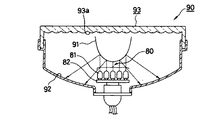
その構成の一例を示すものが、図16であり、照射軸を同一方向として多数のLEDランプ(81)を、基板(82)上に取付けて多点発光部(80)を形成すると共に、この多点発光部(80)の前方に凸面状とした第一反射面(91)を設置して、前記多点発光部(80)からの光を反射させる。 An example of the configuration is shown in FIG. 16, in which a multi-point light emitting section (80) is formed by attaching a large number of LED lamps (81) on the substrate (82) with the irradiation axis as the same direction. A convex first reflecting surface (91) is installed in front of the multipoint light emitting section (80) to reflect light from the multipoint light emitting section (80).
このようにすることで、前記第一反射面(91)により反射が行われる多点発光部(80)からの光は放射状に拡がるものとなり、前記第一反射面(91)の凸面形状を工夫することなどで、フィラメントから放射される白熱電球からの光など、従来使用されていた光源の光の性質に類似させることができる。 By doing in this way, the light from the multipoint light emitting part (80) reflected by the first reflecting surface (91) spreads radially, and the convex shape of the first reflecting surface (91) is devised. By doing so, it is possible to resemble the light property of a light source conventionally used, such as light from an incandescent bulb radiated from a filament.
よって、前記第一反射面(91)で得られた反射光を、更に回転放物面など、従来から使用されてきた形状とした第二反射面(92)で反射させれば、理論上では、照射方向に向かう平行光線など、従来と同様な特性を有する光線が得られるものとなり、第二反射面(92)を覆いレンズカット(93a)が設けられたレンズ(93)を設けることでLED光源とした車両用灯具90が得られるとされている。尚、上記の説明では、後に行う本発明との混乱を避けるため、原文とは符号を変更している。
Therefore, if the reflected light obtained by the first reflecting surface (91) is further reflected by the second reflecting surface (92) having a conventionally used shape such as a paraboloid of revolution, theoretically, By providing a lens (93) that covers the second reflecting surface (92) and is provided with a lens cut (93a), a light beam having characteristics similar to those of the prior art, such as a parallel light beam directed in the irradiation direction, can be obtained. It is said that a
しかしながら、前記多点発光部(80)を構成するためのLEDランプ(81)は、白熱電球のようにほぼ均一な明るさを全周方向に発するものではなく、中心が明るいビーム状の光を比較的に狭い範囲、例えば30°の範囲に放射するものである。従って、前記第一反射面(91)の形状を工夫したとしても、種々の方向からの光が混在するものとなることは避けられない。 However, the LED lamp (81) for constituting the multi-point light emitting section (80) does not emit almost uniform brightness in the entire circumferential direction unlike an incandescent bulb, and emits light in the form of a beam with a bright center. It radiates in a relatively narrow range, for example, a range of 30 °. Therefore, even if the shape of the first reflecting surface (91) is devised, it is inevitable that light from various directions is mixed.
また、上記のように、中心と周辺とに照度差があるビーム状の光を発するLEDランプ(81)からの光を集合させた多点発光部(80)では、第一反射面(91)に均一な明るさの平行光線を供給することは不可能であり、結果としては、第二反射面(92)で反射が行われ、レンズ(93)に達する光にも、相当の光ムラを生じているものとなる。 Further, as described above, in the multi-point light emitting section (80) that collects light from the LED lamp (81) that emits beam-like light having an illuminance difference between the center and the periphery, the first reflecting surface (91) It is impossible to supply a parallel light beam with uniform brightness to the light source. As a result, the light reflected by the second reflecting surface (92) is subjected to considerable light unevenness in the light reaching the lens (93). It will have occurred.
これらの現象は、前記レンズ(93)に施すレンズカット(93a)を強度のものとして、光に強い拡散を行わせて目立たなくするなどで防止せざるを得ず、このように拡散光とすることで光の方向性は失われ、到達距離が減ずるものとなるので、LEDランプを光源とするときには、遠方への視認性に充分な性能を有する照明用灯具を得ることができないという問題点を生じるものとなっていた。 These phenomena must be prevented by making the lens cut (93a) applied to the lens (93) strong and making the light difficult to diffuse to make it inconspicuous. Therefore, the directionality of light is lost, and the reach distance is reduced. Therefore, when an LED lamp is used as a light source, it is impossible to obtain an illumination lamp having sufficient performance for far visibility. It was supposed to occur.
本発明は、上記した従来の課題を解決するための具体的手段として、LED光源と、第一のリフレクタと、第二のリフレクタと、第三のリフレクタと、投影レンズとから構成され、前記LED光源は一方向を中心として光を放出し、その放出方向を主として灯具光軸を境界とする上下いずれか一方とし他方には放出されず、前記第一のリフレクタは前記LED光源の近傍を第一焦点とし、前記投影レンズの焦点の近傍に第二焦点を有する回転楕円面若しくはそれに類似する特性を有する楕円系自由曲面で形成され、前記LED光源の光の放出方向のうち灯具照射方向とは反対側に照射された光を反射し、前記第二のリフレクタは前記LED光源を第一焦点とし、前記LED光源と投影レンズの焦点とを結ぶ軸上の適宜位置に第二焦点を有する回転楕円面若しくはそれに類似する特性を有する楕円系自由曲面で形成され、前記LED光源の光の放出方向のうち灯具照射方向側に照射された光を反射し、前記第三のリフレクタは前記第二のリフレクタの第二焦点を焦点とし、光軸をこの灯具の略照射方向とする回転放物面若しくはそれに類似する特性を有する放物系自由曲面とされていることを特徴とする車両用灯具を提供することで課題を解決するものである。 The present invention includes an LED light source, a first reflector, a second reflector, a third reflector, and a projection lens as specific means for solving the above-described conventional problems. The light source emits light centered on one direction, and the emission direction is mainly one of the upper and lower sides with the lamp optical axis as a boundary and is not emitted to the other. The first reflector is located near the LED light source in the first direction. It is formed of a spheroidal surface having a second focal point in the vicinity of the focal point of the projection lens or an elliptical free-form surface having similar characteristics to the focal point of the projection lens, and is opposite to the lamp irradiation direction in the light emission direction of the LED light source The second reflector has the LED light source as a first focal point, and has a second focal point at an appropriate position on an axis connecting the LED light source and the focal point of the projection lens. It is formed of an elliptical free-form surface having a spheroidal surface or similar characteristics, reflects light irradiated to the lamp irradiation direction side of the light emission direction of the LED light source, and the third reflector is the second reflector. A vehicular lamp characterized in that the second focal point of the reflector is a rotating paraboloid having an optical axis as a substantially illuminating direction of the lamp, or a parabolic free-form surface having similar characteristics. The problem is solved by providing.
LEDランプ、或いは、複数のLEDランプが組合わされたLED光源を、回転楕円反射面など2つの焦点を有する第一のリフレクタの一方の焦点(第一焦点)の位置に設置することで、前記LED光源からの光のほぼ全てを、一定の方向性を持つ光として他の一方の焦点(第二焦点)に収束させることができるものとなり、投影レンズで照射方向に投影することが可能となる。 An LED lamp or an LED light source in which a plurality of LED lamps is combined is installed at the position of one focal point (first focal point) of a first reflector having two focal points such as a spheroid reflecting surface. Almost all of the light from the light source can be converged to the other focal point (second focal point) as light having a certain directionality, and can be projected in the irradiation direction by the projection lens.
加えて、第一のリフレクタがLED光源からの光を捕捉することのできない位置に第二のリフレクタを設け、この第二のリフレクタが捕捉した光を第三のリフレクタで前記投影レンズに入射させ照射光とすることで、LED光源からの光のほぼ全てを同一方向に投射することを可能として第一のリフレクタの第二焦点の近傍に遮光板を設け、投影される光のパターンをヘッドライトに適するものとして、LED光源での照明用灯具の実現を可能とするものである。 In addition, a second reflector is provided at a position where the first reflector cannot capture light from the LED light source, and the light captured by the second reflector is incident on the projection lens by the third reflector and irradiated. By making it light, it is possible to project almost all of the light from the LED light source in the same direction, and a light shielding plate is provided in the vicinity of the second focal point of the first reflector, and the projected light pattern is used as a headlight. Appropriately, it is possible to realize an illumination lamp with an LED light source.
更に、第一〜第三リフレクタ、投影レンズ、遮光板などのを樹脂のインジェクションなどの手段で一体化して形成可能としたことで、光源をLED光源としたために個々の部分が小型化し、組立に精密作業が要求され、製品が高価と成らざるを得なかった状態から組立作用を不要とし、生産性を飛躍的に向上させて画期的なコストダウンを可能とし、この種、LEDを光源とする車両用照明用灯具の実現性を向上させる優れた効果を奏するものである。 Furthermore, the first to third reflectors, projection lenses, light-shielding plates, etc. can be integrated and formed by means such as resin injection, so that the light source is an LED light source, making each part smaller and easier to assemble. Since precision work is required and the product is inevitably expensive, assembly work is not required, productivity is dramatically improved, and epoch-making costs can be reduced. The effect which improves the feasibility of the lighting fixture for vehicles to perform is produced.
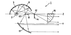
つぎに、本発明を図に示す実施形態及び参考例に基づいて詳細に説明する。なお、実施形態は本願請求項1〜3に係わる発明の具体的な実施形態を示すものであり、参考例(第一参考例〜第七参考例)は本願発明に直接は該当しないが参考として挙げたものである。図1に示すものは本発明に係る車両用灯具1の第一参考例であり、本発明における車両用灯具1は、基本的にはプロジェクタ型と称されている構成に準拠するものであり、LED光源2と、回転楕円面など楕円系とされ、前記LED光源2を第一焦点と略一致させている第一のリフレクタ3と、前記第一のリフレクタ3の第二焦点f2の近傍に設置されている遮光板4と、この遮光板4の近傍に焦点を有する投影レンズ5とから構成されている。
Next, the present invention will be described in detail based on the embodiments and reference examples shown in the drawings. The embodiment shows a specific embodiment of the invention according to
ここで、本発明におけるLED光源2は、フィラメントを発光源とする従来の光源と異なり、発光方向を揃えた複数のLEDランプなどとして形成されるものであり、本発明においては、上方に向かう光を生じるもの、言い換えれば所定の一方向に向かう光のみを生じるものとされている。尚、この説明においては、上下、左右、前後、水平、垂直などの方向は、車体に取付けた車両用灯具を運転席側から見る状態を基準とする。
Here, the
以上に述べたように、LED光源2が上向きの光のみを放射するものとして形成されたことで、このLED光源2からの光を受ける第一のリフレクタ3も当然に、前記LED光源2を上面から覆うものであれば良く、従って、前記第一のリフレクタ3の形状は基本的には回転楕円面と称されるものの、前記LED光源2からの光が放射されることがない長軸Xよりも下方は実質的には不要となり、本発明においても省略されている。
As described above, since the
以上の構成としたことで、第一のリフレクタ3に達したLED光源2からの光は、この第一のリフレクタの第二焦点f2の位置に再度収束され、結像するものとなる。そして、前記第二焦点f2の近傍には遮光板4が設けられ、この車両用灯具1が左側通行用であれば、左の路側側の歩行者、に道路標識などの視認性を向上させるように、エルボと称されて左側に適宜な上向き光を生じているすれ違い用の配光特性を形成する。
With the above configuration, the light from the
このようにして、第二焦点の近傍に前記遮光板4により不要な部分を遮蔽されて形成された配光特性の形状は、前記投影レンズ5により車両の前方に投影されて、例えば左側通行用の車両のすれ違い配光などの照射光とされる。尚、このときに前記遮光板4の形状を適宜に変更すれば、右側通行用のすれ違い配光なども得られるものであることは、いうまでもない。
In this way, the shape of the light distribution characteristic formed by shielding unnecessary portions by the
以上に説明を行った本発明の構成においては、まず、比較的に狭い放射角を有するLEDランプにより、一方向に光を放射するLED光源2を形成すると共に、このLED光源2の光の放射方向に2つの焦点を有する楕円系とした第一のリフレクタ3を組合わせ、第二焦点の位置にLED光源2の像を結像させると共に、遮光板4により配光特性上で不要な部分を遮蔽し、投影レンズ5で投影するものである。
In the configuration of the present invention described above, first, an
従って、光に方向性が与えられLED光源2と、第一のリフレクタ3とを組合わせるときには、例えば、すれ違い用配光など、所望の配光形状を形成するのに最も好都合な方向に光を放射するようにLED光源2を向かわせることが可能となると共に、前記第一のリフレクタ3においても、比較的に狭い範囲に放射されている光を捕捉すれば良いので、捕捉率は向上し、同じ明るさのLED光源を使用した場合にも、より明るい車両用灯具の実現が可能となる。
Therefore, when the directionality is given to the light and the LED
加えて、本発明においては第二のリフレクタ6、第三のリフレクタ7を採用することで、LED光源2に対する一層の光束捕捉率の向上を図るものである。具体的な例としては第一のリフレクタ3は投影レンズ5側に光を反射しなければ成らず、よって、LED光源2から投影レンズ5方向に射出される光に対しては、第一のリフレクタ3では捕捉することはできない。
In addition, in the present invention, by using the second reflector 6 and the
そこで、本発明では第二のリフレクタ6を設けるものであり、この第二のリフレクタ6は前記LED光源2を第一焦点とし、第二焦点f21は、前記LED光源2と、第一のリフレクタ3の第二焦点f2との間の適宜位置に設定されているものとされている。また、第二のリフレクタ6の形状は、第一のリフレクタ3の前方であって、且つ、第一のリフレクタ3からの反射光の光路を妨げないようにされている。
Therefore, in the present invention, the second reflector 6 is provided. The second reflector 6 has the LED
このように形成された第二のリフレクタ6は、その反射光を下方に向かい放射するものとなり、第二焦点f21にLED光源2の像を一旦結像し、焦点を結んだ後には、再度に拡散を行うものとなる。そして、本発明では、上記拡散が行われる範囲に第三のリフレクタ7が設けられている。
The second reflector 6 formed in this way emits the reflected light downward, and once the image of the LED
前記第三のリフレクタ7は、第一のリフレクタ3、第二のリフレクタ6と同様に回転楕円面や、縦方向に割った断面プロファイルが楕円となるような自由曲面、若しくは、それに類似する特性を有する楕円系自由曲面で形成されており、即ち、第一焦点と第二焦点との2つの焦点を有する曲面で形成されている。そして、この第三のリフレクタ7においては、第一焦点は、第二のリフレクタ6の第二焦点f21と一致する位置にあり、第二焦点f22は第一のリフレクタの第二焦点f2に一致、若しくは、その近傍に設けられている。
Similar to the
従って、第二のリフレクタ6で捕捉されたLED光源2からの光も、第三のリフレクタ7を経由して投影レンズ5で前方に照射されるものとなり、車両用灯具1としての光量は増加するものとなる。また、第三のリフレクタ7の第二焦点f22は第一のリフレクタ3の第二焦点f2と、ほぼ同一の位置に設けられているものであるので、遮光板4により配光形状も整えられるものとなる。
Therefore, the light from the LED
ここで発明者の検討に結果によれば、使用する全ての反射面を回転楕円面など一方の焦点から放射される光を他方の焦点に収束する反射面を使用し、LED光源2からの光に一定の方向性を与えるようにすることで、一定の方向性を有する光が得られるものとして、LED光源2においても照明用灯具の実現を可能とするものである。
Here, according to the results of the inventor's investigation, all the reflection surfaces used are reflection surfaces that converge light emitted from one focus, such as a spheroid, to the other focus, and light from the LED
このときの、第一のリフレクタ3に対して、第二、第三のリフレクタ6、7を設けたことによる車両用灯具1としてのLED光源2に対する光束捕捉率の向上は25〜30%程度であり、前記車両用灯具1としての総光量も確実に向上するものとなるが、それに加えて、視認性の向上の面でも有利な点を生じるものであることが判明した。
At this time, the improvement of the light flux capturing rate with respect to the LED
即ち、発明者による試作、検討の結果では、前記第二のリフレクタ6により第二焦点f21に集束するときの光像は、第一のリフレクタの第二焦点f2に生じる光像の径よりも格段に小径のスポット的となる。よって、第三のリフレクタ7により第一のリフレクタ3の第二焦点f2近傍に生じる第二焦点f22も小径となり、即ち、収束率が高く高輝度のスポットが得られるものとなる。
That is, as a result of trial manufacture and examination by the inventor, the optical image when focused on the second focal point f21 by the second reflector 6 is much larger than the diameter of the optical image generated at the second focal point f2 of the first reflector. It becomes a spot of small diameter. Therefore, the second reflector f22 generated in the vicinity of the second focus f2 of the
よって、第三のリフレクタの第二焦点f22を、第一のリフレクタ3の第二焦点f2の中心付近に配置しておけば、車両の正面方向の照度が格段に向上し、遠方に対する視認性が向上するなど、車両用灯具1としての性能の向上が顕著に感じられるものとすることができ、遠方に対する視認性が強化されるなど、性能の向上が著しいものとなる。
Therefore, if the second focal point f22 of the third reflector is arranged in the vicinity of the center of the second focal point f2 of the
また、本発明においては、第二のリフレクタ6で捕捉した光を、更に回転楕円面など2つの焦点を有する第三のリフレクタ7を使用して、第三のリフレクタ7の第二焦点f22に再々収束すると共に、この第三のリフレクタ7の第二焦点f22を前記第一のリフレクタ3の第二焦点f2と、略中心で重ね合わせるものとしている。
In the present invention, the light captured by the second reflector 6 is re-appeared again at the second focal point f22 of the
よって、本発明の構成によれば、第二のリフレクタ6により回収が行われた光は、第三のリフレクタ7を経由して、最終的には第一のリフレクタ3の第二焦点f2と重ね合わされ、遮光板4で形状を整えられた後には、投影レンズ5を介して車両用灯具1の照射光として外部に投影されるものとなる。
Therefore, according to the configuration of the present invention, the light collected by the second reflector 6 is finally superimposed on the second focal point f2 of the
従って、外部から車両用灯具1を看るときには、第二のリフレクタ6、第三のリフレクタ7などが見えることはなく、従来のプロジェクタ型ヘッドライトと同様に投影レンズ5が見えるのみであり、観視者に形状的な違和感を生じさせることはなく、また、大型化も避けられるものとなる。
Therefore, when viewing the
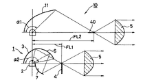
図2は本発明の車両用灯具1が、小型化できると共に、光束利用率も向上させ光量も増加させることが可能となる理由を模式的に示すものであり、図中に符号10で示すものは比較例であり、例えば回転楕円面などとした1枚の第一のリフレクタ11と遮光板40と投影レンズ5とで形成した従来技術の車両用灯具10である。
FIG. 2 schematically shows the reason why the
これに対して、符号1で示すものは本発明に係る車両用灯具1であり、両者を比較すると、同じ大きさ(口径)の投影レンズ5に対してり、本発明では第二のリフレクタ6でもLED光源2からの光を捕捉するので、焦点距離FL1を、比較例の焦点距離FL2に対して略半分の長さに設定すること可能である。
On the other hand, what is denoted by
従って、比較例の構成に対して奥行きを格段に短く設定でき、車両用灯具1としての奥行き方向への寸法も格段に浅く設定できるものとなる。しかも、LED光源2に対する光束を捕捉している角度α2を、比較例の角度α1と比べると充分に大きく、より明るい灯具の実現が可能であることが理解できる。
Therefore, the depth can be set to be much shorter than the configuration of the comparative example, and the dimension in the depth direction as the
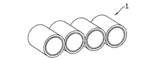
但し、LED光源2からの光量は、現在、この種の灯具の光源として採用されている、例えばハロゲン電球、メタルハライド放電灯などに比較すれば少ないことは明白であるので、図3に示すように複数個を集合して光量不足を補えば良く、このように多数個を組合わせても全体の形状は、現状のものと比べて格別に大型化することもなく、上記に説明した、小型化、浅型化が効果を発揮するものとなる。
However, since the amount of light from the LED
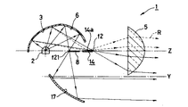
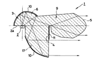
図4に示すものは本発明に係る車両用灯具1の実施形態であり、この車両用灯具1もLEDランプなどLED光源2を光源とするものである点は第一実施例ものと同様である。また、ヘッドライト、フォグライトなど照明用の車両用灯具1の実現を目指すものである点も第一参考例と同様である。
As shown in FIG. 4 is an embodiment of a
尚、符合については、説明が重複し煩雑化を避けるためと、理解を容易とするために、第一参考例とほぼ同じ機能、構成の部分に対しては、一部の説明を省略、または、簡素化する。そして、この実施形態においても、発光方向を上向きとされ、実質的には下方には光を放射することのないようにしてLED光源2が設けられている。
In order to avoid duplication of explanation due to overlapping explanations and to facilitate understanding, some explanations are omitted for parts having substantially the same functions and configurations as the first reference example , or To simplify. Also in this embodiment , the LED
そして、この実施形態においても、一方の光学系として、第一のリフレクタ3、第一の遮光板14、および、投影レンズ5が設けられている。ここで、上記にも説明したように、前記LED光源2が下方に向かう光を生じることがないものとして構成されているので、前記第一のリフレクタ3は第一参考例と同様にLED光源2を上方からのみ覆うものとされている。尚、この実施形態においても、上下、前後、左右など方向を表すときには、車両に取付けた灯具を運転席側から見る状態を基準とする。
Also in this embodiment , the
ここで、前記第一のリフレクタ3は、楕円を長軸Zで回転して得られる回転楕円面や、縦方向に分断した断面プロファイルが楕円となるような自由曲面、または、それらと類似した特性を持つ楕円形自由曲面などの楕円系リフレクタとして形成されるものであり、このときに、前記長軸Zは車両への取付状態において略水平と設定されている。よって、前記第一のリフレクタ3の第二焦点f2は、前記長軸Z上に存在するものとなり、この第二焦点f2の近傍には第一の遮光板14が設けられると共に、前記長軸Zの延長上には、前記第二焦点f2の近傍に焦点を有する投影レンズ5が同軸として設けられている。
Here, the
以上に説明した構成部材は、従来から採用されているプロジェクタ型とした車両用灯具のものとほぼ同等なものであるが、前記第一の遮光板14は、従来例のものが長軸Zの第二焦点f2の近傍に板状部材が垂直に固定された状態として設置されていたが、本発明では、前端(投影レンズ5側となる端部)側が前記第二焦点f2の近傍に位置し、板状部材の面が長軸Zと平行となるように水平方向として設置されている。加えて、前記第一の遮光板14の上側の面14aは、平滑面とされ、更に、光沢メッキ、金属蒸着など適宜な手段により鏡面仕上げが成されている。
The components described above are substantially the same as those of a projector-type vehicular lamp that has been conventionally employed. However, the first light shielding plate 14 has a long axis Z of the conventional example. Although the plate-like member is installed in the vicinity of the second focal point f2 in a vertically fixed state, in the present invention, the front end (the end on the
また、第一のリフレクタ3の前方であり、且つ、前記LED光源2からの光が放射される範囲には、同じく前記LED光源2を第一焦点とし前記長軸Z上に第二焦点f21を有する回転楕円面、若しくは、それに類似する特性を有する楕円系自由曲面として形成された第二のリフレクタ6が設けられている。尚、この第二のリフレクタ6も上記第一のリフレクタ3と同様に縦断面のプロファイルが楕円であり、横断面のプロファイルが放物線である楕円系自由曲面であっても良い。
Further, in the range in front of the
但し、この第二のリフレクタ6が設けられる位置は、前記第一のリフレクタ3が光を反射する方向であるので、形成するときの条件としては、第一のリフレクタ3からの反射光が、その第二焦点f2に収束するときの光路をできるだけ阻害することのないように配慮が行われている。
However, since the position where the second reflector 6 is provided is the direction in which the
また、前記第二のリフレクタ6の第二焦点f21は、前記LED光源2と、第一のリフレクタ3の第二焦点f2との間に設けられるが、このときには、上記にも述べたように、第二のリフレクタ6が、第一のリフレクタ3への直射光、および、第一のリフレクタ3からの反射光の光路を阻害せず、また、第一のリフレクタ3も第二のリフレクタ6に対する干渉をできるだけ少なくする適宜な位置として設定される。
The second focal point f21 of the second reflector 6 is provided between the LED
上記のように第二焦点f21が設定されたことで、前記第二のリフレクタ6の形状は、前記LED光源2を上方かつ前方から覆うような形状となる。そして、前方正面は第一のリフレクタ3からの反射光との干渉を避けるために開口されているので、この第二のリフレクタ6からの反射光は、ほぼ下方に向かい放射されるものとなる。
By setting the second focal point f21 as described above, the shape of the second reflector 6 is a shape that covers the
よって、本発明では、前記第二のリフレクタ6からの反射光が向かう方向、即ち、下方に、前記第二のリフレクタ6の第二焦点f21を焦点とし、光軸Yを長軸Zと略平行とする回転放物面、若しくは、放物面を断面プロファイルに持つ自由曲面、または、それに類似する特性を有する放物系自由曲面とした第三のリフレクタ17が形成されている。
Therefore, in the present invention, the second focal point f21 of the second reflector 6 is focused in the direction in which the reflected light from the second reflector 6 is directed, that is, downward, and the optical axis Y is substantially parallel to the major axis Z. The
また、前記第二焦点f21の近傍には、前記第二のリフレクタ6からの反射光を、前記第三のリフレクタ17の所定範囲に当接させると共に、少なくとも第三のリフレクタ17からの反射光に上向き光を含むことのないようにするための第二の遮光板8が設けられている。尚、前記第三のリフレクタ17を設置するに当たっては、この第三のリフレクタ17からの反射光と、前記投影レンズ5とが干渉しないように位置決めが行われている。
Further, in the vicinity of the second focal point f21, the reflected light from the second reflector 6 is brought into contact with a predetermined range of the
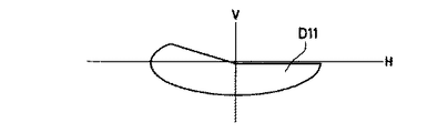
尚、前記第二のリフレクタ6と、第二の遮光板8と、第三のリフレクタ17とにより形成される配光形状は、この車両用灯具1の使用目的により適宜に調整されるものであり、例えば、前記車両用灯具1が、対向車には幻惑を与えず、歩行者側を広く照らすようなすれ違い配光D1(図5参照)を形成させる場合、第一のリフレクタ3と投影レンズ5と第一の遮光板4による光路で図6に示すように、すれ違い配光D1の基本形状D11を形成させる。
The light distribution shape formed by the second reflector 6, the second light shielding plate 8, and the
そして、第二のリフレクタ6と第三のリフレクタ17、および第二の遮光板8による光路で図7に示す補助配光D12、或いは、図8に示す補助配光D13を形成し、上記基本形状D11と組合わせればよい。尚、図7は、第三のリフレクタ17に縦断面プロファイルに放物線を用い、横断面プロファイルに楕円や双曲線を用いるような自由曲面とすることで、左右方向に広く拡散させて水平方向(車両左右方向)への視認性を向上させる配光を形成する場合の例であり、基本形状D11と組合わせることで図5に示す、すれ違い配光D1が得られるものとなる。
Then, the auxiliary light distribution D12 shown in FIG. 7 or the auxiliary light distribution D13 shown in FIG. 8 is formed by the optical path formed by the second reflector 6, the
また、図8に示す補助配光D13は、第三のリフレクタ17に回転放物面などを使用することで、光を集光させた場合であり、これを基本形状D11と組合わせることで、ほぼ基本形状のままで中心光度が一層に向上し、遠方視界に優れる配光特性が得られるものとなる。尚、実際の実施に当たっては、第三のリフレクタ17に水平方向への視認性を向上する部分と、遠方視界を向上させる部分との双方を適宜割合として形成しても良いものである。
Further, the auxiliary light distribution D13 shown in FIG. 8 is a case where the light is condensed by using a rotary paraboloid or the like for the
或いは、前記車両用灯具1がすれ違い配光専用である場合、上記第二のリフレクタ6と、第二の遮光板8と、第三のリフレクタ17とによる組合せで、上向きの光を一切生じないようにしておくのも良い。この場合には、上記したエルボ部分の配光は、第一のリフレクタ3、第一の遮光板4、および、投影レンズ5の側で形成される。この構成としたときの利点は、前記第一の遮光板4に左側通行用と右側通行用とを用意しておくことで、双方の車両用灯具1が生産可能となる。
Alternatively, when the
更に、前記車両用灯具1が、すれ違い配光と、走行配光との切換え式である場合にも、上記第二のリフレクタ6、第二の遮光板8、第三のリフレクタ17による組合せからの配光に上向き光を含んでいなければ、すれ違い配光としたときにも有害となるような影響を与えないので、上記の構成が採用できるものとなる。
Further, when the
また、前記車両用灯具1が、走行配光専用である場合には、上記第二のリフレクタ6、第二の遮光板8、第三のリフレクタ17からの配光に上向き光を含んでいても何らに支障を生じることはなく、よって、この場合には、上記の部品の内から第二の遮光板8を省略しても良いものとなる。
Further, when the
図9は本発明に係る車両用灯具1の第二参考例であり、前の実施形態では、光束利用率を向上させ、明るい車両用灯具1の実現を主目的としていたが、上記にも述べたように、本発明は第一のリフレクタ3と、第二のリフレクタ6とを採用することでLED光源2に対する光束利用率は基本的に充分に向上しているものとなっているので、例えば、車両用灯具1に更なる小型化が要求されたときにも、従来程度の明るさを保つ状態で前面投影面積の一層の小型化が可能である。
FIG. 9 shows a second reference example of the
よって、この第二参考例では、前記第一の遮光板14を従来通りの長軸Zに直角に設置するものとし、第二焦点f2に収束する光像中で、投影レンズ5で投影後には上向光となる成分は、前記遮光板14で完全に遮蔽してしまい、前の実施形態のように第一の遮光板14で反射させ、投影レンズ5の上半部へ入射させることはない。従って、前記投影レンズ5の上半部は不要となるので、この第二参考例では投影レンズ15は上半部を除去したものとなっている。
Therefore, in the second reference example , the first light-shielding plate 14 is installed at a right angle to the long axis Z as in the past, and after projection by the
従って、車両に取付けられた状態で外部から看視が行われるのは、主に投影レンズ15と、第三のリフレクタ17の前面を覆うレンズ(図示せず)であるので、上半部を除去した投影レンズ15とすることで、前方から看視したときの上下方向の寸法を縮小し、小型化を可能とするものである。また、このようにすることで、通常には眞円であると思われている投影レンズ15が半月形となり、斬新なデザインが提供できるものとなる。
Accordingly, since it is mainly the
図10は、本発明に係る車両用灯具1の第三参考例を示すもので、この第三参考例における車両用灯具1は、すれ違い配光と走行配光など、配光形状の切り換えが可能な構成とされている。但し、この実施形態においても、LED光源2、第一のリフレクタ3、第二のリフレクタ6、第三のリフレクタ17のそれぞれは、上記に説明した第一参考例などとほぼ同様な構成である。そして、組立位置など、それぞれの組合せも、ほぼ同様なものとされている。
FIG. 10 shows a third reference example of the
ここで、この第三参考例においては、第一の遮光板24、および、第二の遮光板18が実施形態(図4参照)とは異なる構成のものとされている。即ち、第一の遮光板24においても、第二の遮光板18においても、車両用灯具1にすれ違い配光が要求されているときには、実施形態と同様に長軸Zと平行で水平な状態として設定されている。
Here, in the third reference example , the first
即ち、この第三参考例においても、すれ違い配光用の車両用灯具1として使用されているときの、各部の作用は、図4に示した実施形態の場合と全く同様であり、即ち、すれ違い配光が得られるものであることが明らかであるが、実施形態とは相違し、前記第一の遮光板24と、前記第二の遮光板18とは、それぞれの第二焦点f2、f21側に位置する先端が、その位置から回動により退去可能となるように形成されている。
That is, also in this third reference example , the operation of each part when used as a
そして、前記車両用灯具1に走行配光が要求される状態となり、運転者などにより切り換えのための操作が行われると、前記第一の遮光板24は、図示の状態で上側の端部を回転の中心として、それぞれの受け持つ第二焦点f2、f21の位置から退去する。この結果、第一のリフレクタ3を介して投影レンズ5から投光される光も、第二のリフレクタ6を介して第三のリフレクタ17から投光される光も、上向き光を含むものとなり、図11に示す走行配光DDが得られるものとなる。
When the
図12に示すものは、本発明に係る車両用灯具1の第四参考例であり、上記までの説明は、構成、および、作用を主として説明したものであり、現実にLED光源2を光源として採用したときの、車両用灯具1の各部の大きさなどについて、例えば、第一のリフレクタ3の実際の寸法などについて検討しているものではないが、LED光源2の大きさ、放熱量などから、現状のハロゲン電球、メタルハライド放電灯を光源として採用する車両用灯具に比較して格段に小型化されることが予想される。
FIG. 12 shows a fourth reference example of the
小型化されることは、軽量化、設置場所に対する自由度の増加など、数々の利点が考えられるが、その反面で、小型化された上記各リフレクタ3、6、7の正確な製造には高精度が必要となり、加えて、例えば、第一のリフレクタ3と、遮光板4、投影レンズ5との間の光学的に正確な位置合わせ、同様に、第二のリフレクタ6と第三のリフレクタ7との位置合わせ、など組立にも高精度が要求されるものとなり、部品製造、および、生産工程の複雑化による生産効率の低下などを生じることが予想される。
Miniaturization can have many advantages such as weight reduction and increased flexibility in installation location, but on the other hand, it is difficult to accurately manufacture each of the
この点を解決すべく行われたものが、この第四参考例であり、採用した前記LED光源2からの光を効率良く取り込むように形成されたLED取付位置2a、前記第一のリフレクタ3、投影レンズ5、第二のリフレクタ6、第三のリフレクタ7のそれぞれに対応する部分、および、前記LED光源2からの光が、これらの各リフレクタに反射し投影レンズ5に達する光導路部9の部分が透明部材で一体化して形成されている。尚、この第四参考例は、第一参考例の車両用灯具1(図1参照)と同一の構成の車両用灯具に対して実施されている。
What has been done to solve this point is the fourth reference example , the
また、前記光導路部9中の所定の位置には、例えば、透明部材が充填されず空隙とされた遮光板4も一体に形成されている。そして、前記第一のリフレクタ3、第二のリフレクタ6、第三のリフレクタ7に対応する透明部材の外面には、例えば、アルミニウムの真空蒸着などが行われて鏡面処理10が行われており、また、遮光板4とする部分には必要に応じて黒色不透明塗料が塗布されて遮光処理11が行われている。尚、遮光処理11は、前記遮光板4以外の部分であり外光が光導路部9などに入射すると幻惑光を発生するなど不都合を生じる場所にも形成しても良いものである。また、遮光板4とする部分は、不透明な樹脂を用いた2色成形や、金属や不透明樹脂部材を導光路の中にインサート成型するような手段で形成しても良い。
Further, at a predetermined position in the
以上、説明のように構成した第四参考例の作用、効果について説明を行うと、光を発するLED光源2から、光が外部に放出される投影レンズ5までに経由するリフレクタである第一のリフレクタ3、第二のリフレクタ6、第三のリフレクタ7、これらの光の内から不要の部分を遮光する遮光板4の全てが、透明部材である光導路部9で所定位置に取付けられた状態として金型による射出成形などの手段により一体成形されるものとなる。
The operation and effect of the fourth reference example configured as described above will be described. The first reflector is a reflector that passes from the LED
よって、多数を生産するときにも金型精度と同一精度のものが複製できるものとなり、製品バラツキの要因となる組立作業をほぼ完全に生産工程からなくすることが可能であるので、生産性が向上すると共に、品質の均一性が向上し、例えば、前照灯として使用する目的で複数を組み合わせるときにも、それぞれに配光形状の差が少ないので、組合せも容易であり、所定の配光が容易に得られるものとなる。 Therefore, when producing a large number, the same precision as the mold accuracy can be duplicated, and assembly work that causes product variation can be almost completely eliminated from the production process. In addition to improving the uniformity of quality, for example, when combining multiple units for the purpose of use as a headlamp, there is little difference in the shape of the light distribution, so the combination is easy and the predetermined light distribution Can be easily obtained.
図13に示すものは、同じく本発明に係る車両用灯具1の第五参考例であり、この第五参考例も原則的には、LED取付位置2a、第一のリフレクタ3、第二のリフレクタ6、第三のリフレクタ7、遮光板4など、お互いが精度の高い位置関係で配置されることが好ましい部品が一体化して形成されているものである点は、前の第四参考例と同様である。
FIG. 13 shows a fifth reference example of the
但し、ここで、第四参考例で説明したLED光源2から放射された時から、投影レンズ5から大気中に放出される時まで高屈折の透明部材で形成された光導路部9中に光が閉じこめられている構成では、投影レンズ5には大気と接触する面が、外側の一面しか存在せず、屈折効率も低くなり、所望の照射角を得るための曲率も極度に強いものが要求されたり、或いは、光導路部9を形成する部材に極度に高屈折率のもの要求されるなど、実現性に問題を生じる場合がある。
However, here, light is emitted into the
この点を解決するために、この第五参考例では、前記投影レンズ5の部分は、従来例のプロジェクタ型とした車両用灯具と同様に分離して形成し、従来例の部材(例えばガラス)、形状などを使用可能として、上記した問題点を生じないようにしている。
In order to solve this problem, in the fifth reference example , the
図14に示すものは、本発明に係る車両用灯具1の第六参考例であり、この第六参考例は第二参考例と同じ構成の車両用灯具1、即ち、第三のリフレクタ17が放物面系として形成された構成の車両用灯具1(図4参照)に対して実施されている。そして、その主たる目的とするところは、光源であるLED光源2が小型化されたために、全体的に小型化された各リフレクタ間の相互位置関係、形状精度などを高く保ち、且つ、生産工程を簡素化するために、透明部材による光導路部9を設けることで各部品を一体化することにある。
FIG. 14 shows a sixth reference example of the
但し、図4と、図14とを比較した場合に明らかなように、遮光板8のように光導路部9と干渉し取付けること自体が不可能となる部品も生じてしまう可能性がある。このような場合には、例えば、第三のリフレクタ17、または、第二のリフレクタ6を設ける範囲、或いは角度などを調整して上向き光を生じないようにすればよい。
However, as is clear when FIG. 4 is compared with FIG. 14, there may be a part such as the light shielding plate 8 that interferes with the
図15に示すものは、本発明に係る車両用灯具1の第七参考例であり、この第七参考例は、第四参考例(図12参照)と第五参考例(図13参照)との場合と同じく、光学的には独立していることが好ましい投影レンズ5を、LED取付位置2a、第一のリフレクタ3、第二のリフレクタ6、第三のリフレクタ17、遮光板4などと分離して形成したものであり、得られる作用、効果も第四参考例と第五参考例の場合と、ほぼ同様であるので、ここでの詳細な説明は省略する。
FIG. 15 shows a seventh reference example of the
但し、第三のリフレクタ17の前面から射出される光で、車両の左右方向の照明を行うように図るなど、平行光線以外の光をこの部分から放射させようとするときには、第三のリフレクタ17の前面の当該の部分にレンズカット17aを設けるなどは自在である。
However, when the light emitted from the front surface of the
以上に説明したように、光源をLED化したことで、リフレクタ、投影レンズなどが小型化し、形状にも、組立にも高精度が要求されるものとなるときには、光源、リフレクタ、投影レンズ間を透明部材で充填して光導路部9とし、主要部品を一体化し、例えば金型による樹脂成形が可能とすることで、均一な精度のものを、大量且つ迅速に生産可能とし、例えば複数の組合せを容易として、必要な明るさの照明用の車両用灯具の実現を可能とするものである。
As explained above, when the light source is made into an LED, the reflector, the projection lens, etc. are downsized, and when high accuracy is required for both the shape and the assembly, the space between the light source, the reflector, and the projection lens is used. Filling with a transparent member to form an
1…車両用灯具
2…LED光源
3…第一のリフレクタ
4、14…第一の遮光板
5…投影レンズ
6…第二のリフレクタ
7、17…第三のリフレクタ
17a…レンズカット
8、18…第二の遮光板
9…光導路部
10…鏡面処理
11…遮光処理
DESCRIPTION OF
Claims (3)
前記LED光源は一方向を中心として光を放出し、その放出方向を主として灯具光軸を境界とする上下いずれか一方とし他方には放出されず、
前記第一のリフレクタは前記LED光源の近傍を第一焦点とし、前記投影レンズの焦点の近傍に第二焦点を有する回転楕円面若しくはそれに類似する特性を有する楕円系自由曲面で形成され、前記LED光源の光の放出方向のうち灯具照射方向とは反対側に照射された光を反射し、
前記第二のリフレクタは前記LED光源を第一焦点とし、前記LED光源と投影レンズの焦点とを結ぶ軸上における前記第一のリフレクタの回転軸上を含むその近傍位置に第二焦点を有する回転楕円面若しくはそれに類似する特性を有する楕円系自由曲面で形成され、前記LED光源の光の放出方向のうち灯具照射方向側に照射された光を反射し、
前記第三のリフレクタは前記第二のリフレクタの第二焦点を焦点とし、光軸をこの灯具の略照射方向とする回転放物面若しくはそれに類似する特性を有する放物系自由曲面とされていることを特徴とする車両用灯具。 An LED light source, a first reflector, a second reflector, a third reflector, and a projection lens;
The LED light source emits light around one direction, and the emission direction is mainly emitted from the lamp optical axis as a boundary and is not emitted to the other.
The first reflector is formed of an elliptical free-form surface having a first focal point in the vicinity of the LED light source and a second focal point in the vicinity of the focal point of the projection lens, or an elliptical free-form surface having characteristics similar thereto. Reflects the light emitted on the opposite side of the light emission direction of the light from the light source,
The second reflector has the LED light source as a first focal point, and has a second focal point at a position near the rotation axis of the first reflector on the axis connecting the LED light source and the focal point of the projection lens. It is formed of an elliptical free-form surface having an elliptical surface or similar characteristics, and reflects the light irradiated on the lamp irradiation direction side of the light emission direction of the LED light source,
The third reflector is a rotating paraboloid having a second focal point of the second reflector as a focal point and having an optical axis as a substantially irradiation direction of the lamp, or a parabolic free-form surface having similar characteristics. A vehicular lamp characterized by the above.
前記第二のリフレクタの第二焦点の近傍に配置される第二の遮光板とが設けられ、その少なくとも一方は可動が可能とされており、この車両用灯具の光軸に対して平行位置と、光線を遮らない位置とに設定可能な構成とされていることを特徴とする請求項1記載の車両用灯具。 A first light-shielding plate disposed in the vicinity of a second focal point of the first reflector in the vehicle lamp;
A second light shielding plate disposed in the vicinity of the second focal point of the second reflector, at least one of which is movable, and is positioned parallel to the optical axis of the vehicular lamp. The vehicular lamp according to claim 1, wherein the vehicular lamp is configured to be set at a position that does not block the light beam.
Priority Applications (1)
| Application Number | Priority Date | Filing Date | Title |
|---|---|---|---|
| JP2009118951A JP4780809B2 (en) | 2004-02-27 | 2009-05-15 | Vehicle lighting |
Applications Claiming Priority (5)
| Application Number | Priority Date | Filing Date | Title |
|---|---|---|---|
| JP2004054021 | 2004-02-27 | ||
| JP2004054010 | 2004-02-27 | ||
| JP2004054021 | 2004-02-27 | ||
| JP2004054010 | 2004-02-27 | ||
| JP2009118951A JP4780809B2 (en) | 2004-02-27 | 2009-05-15 | Vehicle lighting |
Related Parent Applications (1)
| Application Number | Title | Priority Date | Filing Date |
|---|---|---|---|
| JP2004342499A Division JP4335785B2 (en) | 2004-02-27 | 2004-11-26 | Vehicle lighting |
Publications (2)
| Publication Number | Publication Date |
|---|---|
| JP2009187960A JP2009187960A (en) | 2009-08-20 |
| JP4780809B2 true JP4780809B2 (en) | 2011-09-28 |
Family
ID=41070957
Family Applications (1)
| Application Number | Title | Priority Date | Filing Date |
|---|---|---|---|
| JP2009118951A Expired - Fee Related JP4780809B2 (en) | 2004-02-27 | 2009-05-15 | Vehicle lighting |
Country Status (1)
| Country | Link |
|---|---|
| JP (1) | JP4780809B2 (en) |
Families Citing this family (5)
| Publication number | Priority date | Publication date | Assignee | Title |
|---|---|---|---|---|
| JP2011165600A (en) * | 2010-02-15 | 2011-08-25 | Koito Mfg Co Ltd | Vehicular illumination lamp |
| JP5865041B2 (en) * | 2010-12-03 | 2016-02-17 | 株式会社小糸製作所 | Lighting fixtures for vehicles |
| JP5937310B2 (en) * | 2011-07-19 | 2016-06-22 | 株式会社小糸製作所 | Vehicle headlamp |
| JP6235237B2 (en) * | 2013-05-17 | 2017-11-22 | 株式会社小糸製作所 | Vehicle lighting |
| KR102392310B1 (en) * | 2017-07-24 | 2022-05-02 | 현대모비스 주식회사 | Illumination device foe vehicle |
Family Cites Families (6)
| Publication number | Priority date | Publication date | Assignee | Title |
|---|---|---|---|---|
| JP2000348508A (en) * | 1999-06-04 | 2000-12-15 | Stanley Electric Co Ltd | Lighting fixture for vehicle |
| JP3488960B2 (en) * | 2000-02-18 | 2004-01-19 | スタンレー電気株式会社 | Vehicle headlights |
| JP4038383B2 (en) * | 2002-03-22 | 2008-01-23 | スタンレー電気株式会社 | Vehicle headlamp |
| FR2839139B1 (en) * | 2002-04-25 | 2005-01-14 | Valeo Vision | LUMINAIRE-FREE ELLIPTICAL LIGHTING MODULE COMPRISING A CUT-OFF LIGHTING BEAM AND PROJECTOR COMPRISING SUCH A MODULE |
| JP2003338209A (en) * | 2002-05-20 | 2003-11-28 | Koito Mfg Co Ltd | Headlamp for vehicle |
| JP2004039545A (en) * | 2002-07-05 | 2004-02-05 | Nissan Motor Co Ltd | Vehicle lamp |
-
2009
- 2009-05-15 JP JP2009118951A patent/JP4780809B2/en not_active Expired - Fee Related
Also Published As
| Publication number | Publication date |
|---|---|
| JP2009187960A (en) | 2009-08-20 |
Similar Documents
| Publication | Publication Date | Title |
|---|---|---|
| JP4335785B2 (en) | Vehicle lighting | |
| JP4089866B2 (en) | Light projecting unit and LED vehicle illumination lamp comprising the light projecting unit | |
| US20070171665A1 (en) | High-intensity zone LED projector | |
| JP2945376B1 (en) | Light fixture | |
| KR100385605B1 (en) | Electric Lamp | |
| CN210740277U (en) | High-low beam integrated headlamp module, headlamp and vehicle | |
| CN109282234B (en) | Projection unit for automobile dipped headlight and automobile lamp thereof | |
| JP4044352B2 (en) | head lamp | |
| JP2000348508A (en) | Lighting fixture for vehicle | |
| CN210740276U (en) | Low-beam reflection type headlamp module and vehicle | |
| JP4780809B2 (en) | Vehicle lighting | |
| JP5033530B2 (en) | Light source unit for vehicle lamp | |
| CN111076141A (en) | Car light module and car light | |
| CN208282013U (en) | Dipped beam system | |
| KR101243358B1 (en) | Headlight for vehicle | |
| JP2022521121A (en) | Optical elements for headlamps, headlamp modules, car lights, and vehicles | |
| KR20220044799A (en) | Vehicle lamp optical element assembly, vehicle lighting device, vehicle lamp and vehicle | |
| KR20010085232A (en) | Headlamp for vehicle | |
| CN210662689U (en) | Reflection-type headlamp module, headlamp and vehicle | |
| JP2002117710A (en) | Headlamp | |
| JP2004087435A (en) | Head lamp | |
| CN211450764U (en) | Car light module and car light | |
| JP6222982B2 (en) | Light source device | |
| JP2000076907A (en) | Headlamp for motor vehicle | |
| CN112762407A (en) | Short-distance beam optical module and car lamp |
Legal Events
| Date | Code | Title | Description |
|---|---|---|---|
| A621 | Written request for application examination |
Free format text: JAPANESE INTERMEDIATE CODE: A621 Effective date: 20090515 |
|
| A977 | Report on retrieval |
Free format text: JAPANESE INTERMEDIATE CODE: A971007 Effective date: 20101007 |
|
| A131 | Notification of reasons for refusal |
Free format text: JAPANESE INTERMEDIATE CODE: A131 Effective date: 20101102 |
|
| A521 | Request for written amendment filed |
Free format text: JAPANESE INTERMEDIATE CODE: A523 Effective date: 20110104 |
|
| TRDD | Decision of grant or rejection written | ||
| A01 | Written decision to grant a patent or to grant a registration (utility model) |
Free format text: JAPANESE INTERMEDIATE CODE: A01 Effective date: 20110607 |
|
| A01 | Written decision to grant a patent or to grant a registration (utility model) |
Free format text: JAPANESE INTERMEDIATE CODE: A01 |
|
| A61 | First payment of annual fees (during grant procedure) |
Free format text: JAPANESE INTERMEDIATE CODE: A61 Effective date: 20110704 |
|
| FPAY | Renewal fee payment (event date is renewal date of database) |
Free format text: PAYMENT UNTIL: 20140715 Year of fee payment: 3 |
|
| R150 | Certificate of patent or registration of utility model |
Ref document number: 4780809 Country of ref document: JP Free format text: JAPANESE INTERMEDIATE CODE: R150 Free format text: JAPANESE INTERMEDIATE CODE: R150 |
|
| R250 | Receipt of annual fees |
Free format text: JAPANESE INTERMEDIATE CODE: R250 |
|
| R250 | Receipt of annual fees |
Free format text: JAPANESE INTERMEDIATE CODE: R250 |
|
| R250 | Receipt of annual fees |
Free format text: JAPANESE INTERMEDIATE CODE: R250 |
|
| R250 | Receipt of annual fees |
Free format text: JAPANESE INTERMEDIATE CODE: R250 |
|
| R250 | Receipt of annual fees |
Free format text: JAPANESE INTERMEDIATE CODE: R250 |
|
| R250 | Receipt of annual fees |
Free format text: JAPANESE INTERMEDIATE CODE: R250 |
|
| R250 | Receipt of annual fees |
Free format text: JAPANESE INTERMEDIATE CODE: R250 |
|
| LAPS | Cancellation because of no payment of annual fees |