JP4779383B2 - Digital camera - Google Patents
Digital camera Download PDFInfo
- Publication number
- JP4779383B2 JP4779383B2 JP2005051339A JP2005051339A JP4779383B2 JP 4779383 B2 JP4779383 B2 JP 4779383B2 JP 2005051339 A JP2005051339 A JP 2005051339A JP 2005051339 A JP2005051339 A JP 2005051339A JP 4779383 B2 JP4779383 B2 JP 4779383B2
- Authority
- JP
- Japan
- Prior art keywords
- focus
- accumulation
- sensor
- storage
- evaluation value
- Prior art date
- Legal status (The legal status is an assumption and is not a legal conclusion. Google has not performed a legal analysis and makes no representation as to the accuracy of the status listed.)
- Expired - Fee Related
Links
Images


Landscapes
- Focusing (AREA)
- Automatic Focus Adjustment (AREA)
- Studio Devices (AREA)
Description
本発明は、位相差検出方式およびコントラスト検出方式により撮影光学系の焦点調節状態を検出する焦点検出装置、および、その焦点検出装置を備えたデジタルカメラに関する。 The present invention relates to a focus detection device that detects a focus adjustment state of a photographing optical system using a phase difference detection method and a contrast detection method, and a digital camera including the focus detection device.
位相差検出方式により撮影レンズを合焦点近傍に駆動した後に、コントラスト検出方式により焦点調節状態の微調整を行うという、位相差検出方式およびコントラスト検出方式のそれぞれの利点を活用したものが知られている(例えば、特許文献1参照)。この場合、CCDラインセンサ等の光電変換素子が用いられる位相差方式のAFセンサは撮影画面の一部の被写体光のみを検出しているが、コントラスト方式の撮像素子の場合には撮影画面全体の被写体光を検出し、焦点検出エリアに相当する画像領域の信号を用いて焦点評価値を算出するようにしている。 It is known to utilize the advantages of both the phase difference detection method and the contrast detection method, in which after the photographic lens is driven near the focal point by the phase difference detection method, the focus adjustment state is finely adjusted by the contrast detection method. (For example, refer to Patent Document 1). In this case, a phase difference type AF sensor using a photoelectric conversion element such as a CCD line sensor detects only a part of the subject light on the shooting screen, but in the case of a contrast type imaging device, the entire shooting screen is detected. Subject light is detected, and a focus evaluation value is calculated using a signal in an image area corresponding to the focus detection area.
ところで、AFセンサや撮像素子には、CCDのような蓄積型センサが用いられている。蓄積型センサでは、入射する光量に応じて蓄積時間を決定し、適切なレベルの信号が得られるように制御する必要がある。この蓄積時間が適切でなく短すぎると、出力レベルが低くなって検出精度の低下を招いたり、検出不能の原因となる。逆に、蓄積時間が長すぎると、出力が飽和状態となってしまって検出不能となる。 Incidentally, a storage type sensor such as a CCD is used for the AF sensor and the image sensor. In the accumulation type sensor, it is necessary to determine the accumulation time in accordance with the amount of incident light and to control so as to obtain an appropriate level signal. If the accumulation time is not appropriate and is too short, the output level is lowered, leading to a decrease in detection accuracy, or the cause of detection failure. On the other hand, if the accumulation time is too long, the output becomes saturated and cannot be detected.
例えば、AFセンサにより検出される被写体領域の被写体輝度が、撮影画面の他の領域に比べて低い場合を考える。この場合、測光センサから得られる画面全体の被写体輝度情報に基づいて、撮像素子の蓄積時間ExTを撮影画面全体に対して適切な値に設定すると、AFセンサが捉えている低輝度な被写体に対応する出力信号は低い値になる。そのため、コントラスト検出法により精度良く焦点調節を行うことができないという問題があった。 For example, consider a case where the subject brightness of the subject region detected by the AF sensor is lower than other regions of the shooting screen. In this case, if the accumulation time ExT of the image sensor is set to an appropriate value for the entire photographing screen based on the subject luminance information of the entire screen obtained from the photometric sensor, it corresponds to the low-luminance subject captured by the AF sensor. The output signal is low. For this reason, there is a problem that the focus adjustment cannot be performed with high accuracy by the contrast detection method.
請求項1の発明によるデジタルカメラは、撮影光学系を通過した被写体光を撮像する蓄積型撮像素子と、前記蓄積型撮像素子による撮影画面内に設定された焦点検出エリアに対応する被写体光を検出する蓄積型光電変換素子と、前記蓄積型光電変換素子からの出力信号に基づいて前記撮影光学系の焦点調節状態を表すフォーカス情報を算出するフォーカス情報算出手段と、前記蓄積型撮像素子の撮像信号のうち、前記焦点検出エリアに対応する信号に基づいて焦点評価値を算出する評価値演算手段と、前記撮影画面内の前記焦点検出エリアよりも広い撮影画面全体または所定領域の範囲に対応する被写体光を測光して測光信号を出力する測光手段と、前記焦点検出エリアに対応する被写体光を検出する際の前記蓄積型光電変換素子の蓄積時間に基づいて、前記焦点評価値を算出するために前記撮像信号を取得する時の前記蓄積型撮像素子を蓄積制御する第1の制御手段と、前記測光手段の測光信号に基づき、撮影動作時の前記蓄積型撮像素子を蓄積制御する第2の制御手段と、を備えることを特徴とする。 According to a first aspect of the present invention, a digital camera according to a first aspect of the present invention detects a subject-type light corresponding to a focus detection area set in a photographing screen by the storage-type image pickup device and a storage-type image pickup device that picks up subject light that has passed through the photographing optical system. A storage type photoelectric conversion element, focus information calculation means for calculating focus information representing a focus adjustment state of the photographing optical system based on an output signal from the storage type photoelectric conversion element, and an image pickup signal of the storage type image pickup element An evaluation value calculating means for calculating a focus evaluation value based on a signal corresponding to the focus detection area, and an object corresponding to the entire shooting screen or a range of a predetermined area larger than the focus detection area in the shooting screen Photometric means for measuring light and outputting a photometric signal, and storage time of the storage type photoelectric conversion element when detecting subject light corresponding to the focus detection area Based on the first control means for controlling the accumulation of the storage type image sensor when acquiring the imaging signal to calculate the focus evaluation value, and based on the photometric signal of the photometric means, And a second control means for controlling accumulation of the accumulation type image pickup device.
本発明によれば、蓄積型光電変換素子の蓄積時間に基づいて蓄積型撮像素子を蓄積制御するようにしたので、蓄積型撮像素子に対する適切な蓄積制御を行うことができ、蓄積型光電変換素子が捉えている被写体に対する焦点評価値演算を精度良く行うことができる。 According to the present invention, since the accumulation type image pickup element is subjected to accumulation control based on the accumulation time of the accumulation type photoelectric conversion element, it is possible to perform appropriate accumulation control for the accumulation type image pickup element. The focus evaluation value calculation can be performed with high accuracy on the subject captured by the camera.
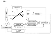
以下、図を参照して本発明を実施するための最良の形態について説明する。図1は本発明の一実施の形態を示す図であり、本発明による焦点検出装置を備えたAFデジタルカメラの要部構成を示すブロック図である。図1に示すAFデジタルカメラでは、撮像素子3と撮影レンズ1との間にミラーユニット2が設けられており、撮影を行わない状態(非撮影状態)では、図1に示すようにミラーユニット2は光軸上に配置されている。撮影レンズ1の焦点調節は、モータ13によって撮影レンズ1のフォーカスレンズを駆動することにより行われる。モータ13はレンズ駆動制御部8により駆動制御される。
Hereinafter, the best mode for carrying out the present invention will be described with reference to the drawings. FIG. 1 is a diagram showing an embodiment of the present invention, and is a block diagram showing a main configuration of an AF digital camera provided with a focus detection apparatus according to the present invention. In the AF digital camera shown in FIG. 1, the
ミラーユニット2はハーフミラー201と全反射ミラー202とを有しており、非撮影状態では撮影レンズ1を通過した被写体光束の一部がハーフミラー201により反射され、測光センサ9へと導かれる。測光センサ9はハーフミラー201で反射された被写体光束を検出し、その検出結果から被写体の輝度情報を取得する。得られた被写体輝度情報は蓄積時間設定部7へと出力される。一方、ハーフミラー201を透過した被写体光束は、全反射ミラー202により反射されAFセンサ5へと導かれる。一方、撮影時にはミラーユニット2は光軸上から待避し、撮影レンズ1を通過した被写体光束は全て撮像素子3へと達する。
The
撮像素子3は、撮影およびコントラスト検出方式による焦点調節を行うためのエリアセンサであり、CCDやCMOS等の蓄積型センサが用いられる。また、AFセンサ5もCCDやCMOS等の蓄積型センサであるが、一般的にはラインセンサが用いられる。蓄積型センサから出力される撮像信号のレベルは、センサの各画素に入射する光量に応じて異なり、光量が大きいほど出力信号レベルも大きくなる。10は撮像素子3のコントロール部であり、撮像素子3で撮像を行う際の蓄積制御や画像信号の読み出し制御等を行う。AFセンサにも同様の制御を行うコントロール部11が設けられている。
The
撮影を行う場合には、蓄積時間設定部7は、測光センサ9で得られた撮影画面全体または所定領域の被写体輝度情報に基づいて、撮像素子3への露光量が最適となるように撮影用蓄積時間ExTを設定し、その蓄積時間ExTをコントロール部10へと出力する。コントロール部10は、入力された撮影用蓄積時間ExTに基づいて撮像素子3の蓄積開始および蓄積終了を行わせる。
When shooting, the accumulation time setting unit 7 is used for shooting so that the exposure amount to the
また、焦点調節動作を行う場合、本実施の形態では、AFセンサ5の出力信号に基づく位相差検出方式による焦点調節と、撮影用撮像素子3の映像信号に基づくコントラスト検出方式の焦点調節とを併用して行う。具体的には、カメラのレリーズボタンが半押しされると、ミラーユニット2を光軸上に配設した状態でAFセンサ5による信号を取得する。なお、このときのAFセンサ5の蓄積時間AFTは蓄積時間設定部7で算出される。この蓄積時間決定方法としては、例えば、AFセンサ5の近傍にモニタセンサ12を配設し、そのモニタセンサ12の出力等に基づいて算出される。例えば、蓄積開始からのモニタセンサ12の出力値を積算し、その積算値が所定レベルに達したならばAFセンサ5の蓄積動作を終了する。
In the case of performing the focus adjustment operation, in the present embodiment, the focus adjustment by the phase difference detection method based on the output signal of the
AFセンサの出力信号はデフォーカス量演算部6に入力され、デフォーカス量演算部6は位相差検出方式によりフォーカス情報であるデフォーカス量を算出する。算出されたデフォーカス量はレンズ駆動制御部8に入力され、レンズ駆動制御部8はモータ13を駆動してデフォーカス量に基づくレンズ位置へとフォーカスレンズを移動する。その結果、撮影レンズ1のフォーカスレンズは合焦位置の近傍に配置される。
The output signal of the AF sensor is input to the defocus amount calculation unit 6, and the defocus amount calculation unit 6 calculates a defocus amount that is focus information by a phase difference detection method. The calculated defocus amount is input to the lens
次いで、カメラのレリーズボタンが半押しされるとミラーユニット2を光軸上から待避させ、撮像素子3による撮像を行い映像信号を評価値演算部4に入力する。なお、詳細は後述するが、このときの蓄積時間IAFTは上述した撮影用蓄積時間ExTと異なっている。評価値演算部4では、焦点検出エリア内の映像信号に基づいて所定帯域の高周波成分を抽出する。そして、抽出した高周波成分の絶対値を積分して焦点検出エリア内の被写体像に関する焦点評価値を算出する。算出された焦点評価値はレンズ駆動制御部8に入力され、レンズ駆動制御部8は焦点評価値に基づいて撮影レンズ1のフォーカスレンズを駆動することにより焦点調節を行う。上述した位相差検出方式による調節動作により合焦位置の近傍へと駆動されたフォーカスレンズは、続いて行われるコントラスト検出方式による焦点調節動作により、さらに精度良く焦点調節が行われることになる。
Next, when the release button of the camera is half-pressed, the
図2は撮影画面20内に設定された焦点検出エリアの一例を示したものであり、画面中央に焦点検出エリア21が一つ設定されている。22はAFセンサ5により検出される領域を表したものである。上述した焦点評価値はこの焦点検出エリア21内の撮像信号に基づいて算出されるが、精度良く焦点評価値を得るためには焦点検出エリア21の面積をある程度大きくする必要がある。一般的には、ラインセンサで構成されるAFセンサ5の検出領域22よりも焦点検出エリア21の方が幅(図2の場合は縦幅)が大きい。
FIG. 2 shows an example of the focus detection area set in the photographing
ところで、AFセンサ5の検出信号を取得する際には、上述したモニタセンサ12の出力信号に基づく蓄積時間AFTで検出する。モニタセンサ12は検出領域22の被写体光束を検出しており、その被写体光束に基づいて、AFセンサ5の出力信号レベルが適切になるように蓄積時間AFTが決定される。一方、測光センサ9からは撮影画面全体の被写体光束に基づく輝度情報が蓄積時間設定部7に出力され、撮影時の露光量が最適となるように撮影用蓄積時間ExTが決定される。そのため、画面中央部の焦点検出エリア21の映像信号のみを用いて焦点評価値を算出する場合には、信号レベルが正確な焦点評価値を得るのに不適切となるおそれがある。
By the way, when the detection signal of the
蓄積型センサが用いられている撮像素子3やAFセンサ5では、充分な信号レベルが得られるように、被写体輝度が低い場合の蓄積時間は被写体輝度が高い場合に比べて長く設定される。例えば、検出領域22は暗いが画面全体としては充分な明るさの被写体の場合、AFセンサ5の蓄積時間AFTは暗い検出領域22に対して適切な信号レベルが得られるように設定される。一方、撮像素子3の撮影用蓄積時間ExTは画面全体の輝度に基づいて信号レベルが適切になるように設定されるため、AFセンサ5の蓄積時間AFTに比べて短めとなりやすい。
In the
前述したように、従来の焦点検出装置では撮影時と同じ撮影用蓄積時間ExTで撮像を行い、そのときの焦点検出エリア21内の映像信号に基づいて焦点評価値を算出するようにしている。そのため、AFセンサ5が捉えている検出領域22の被写体に対しては蓄積時間ExTが適切値より短くなり、その被写体に対応する出力信号が低くなる。その結果、AFセンサ5が捉えている被写体を精度良く焦点調節ができなかったり、また、検出領域22の被写体のコントラストが得られず、焦点検出エリア21の別の被写体のコントラストで焦点調節が行われてしまったりする不具合が生じる。
As described above, in the conventional focus detection apparatus, imaging is performed with the same shooting accumulation time ExT as that during shooting, and the focus evaluation value is calculated based on the video signal in the
そこで、本実施の形態では、焦点評価値を算出するための撮像を行う場合には、AFセンサ5が捉えている被写体の輝度に基づいて、焦点評価値取得の際の撮像素子3の蓄積時間IAFTを設定するようにした。図3は焦点調節動作を説明するフローチャートである。この図3に示す焦点調節動作は、例えば、カメラのレリーズボタンが半押しされるとスタートする。
Therefore, in the present embodiment, when imaging for calculating the focus evaluation value is performed, the accumulation time of the
ステップS1では、蓄積時間設定部7により、AFセンサ5の蓄積時間AFTを設定する。設定は、上述したようにAFセンサ5の近傍に設けられたモニタセンサ12の出力に基づいて、AFセンサ5にとって最適値となるように行われる。ステップS2では、ステップS1で設定された蓄積時間AFTに基づいてAFセンサ5の蓄積が行われ、AFセンサ5の出力信号に基づいてデフォーカス量演算部6でデフォーカス量DFが算出される。
In step S <b> 1, the accumulation time setting unit 7 sets the accumulation time AFT of the
ステップS3では、レンズ駆動制御部8において、ステップS2で算出されたデフォーカス量DFが予め設定された所定量以内であるか否かを判定する。この所定量とは、位相差検出法による焦点調節動作からコントラスト検出方式による焦点調節動作への切り換えタイミングを決めるためのものであり、現在のレンズ位置が合焦位置に充分近いか否かをデフォーカス量DFで判定している。
In step S3, the lens
ステップS3でデフォーカス量DFが所定量以内と判定されるとステップS5へ進む。一方、ステップS3でデフォーカス量DFが所定量より大きいと判定されるとステップS4へ進み、撮影レンズ1をデフォーカス量DFだけ駆動する。ステップS4の処理が終了したならばステップS2へ戻り、再びAFセンサ5による検出を行ってデフォーカス量DFを算出する。そして、レンズ位置が合焦位置に充分近くなってデフォーカス量DFが所定量以内と判定されるまで、ステップS2〜S4の処理が繰り返し実行される。
If it is determined in step S3 that the defocus amount DF is within the predetermined amount, the process proceeds to step S5. On the other hand, if it is determined in step S3 that the defocus amount DF is larger than the predetermined amount, the process proceeds to step S4, and the photographing lens 1 is driven by the defocus amount DF. If the process of step S4 is completed, the process returns to step S2, and detection by the
ステップS5では、蓄積時間設定部7において、コントラスト検出法による焦点調節を行う際の撮像素子3の蓄積時間IAFTを設定する。本実施の形態では、AFセンサ5のために設定された蓄積時間AFTに基づいて、次式(1)により蓄積時間IAFTを算出する。式(1)において、αcはAFセンサ5と撮像素子3との感度比である。すなわち、AFセンサ5が捉えているものと同一の被写体のコントラストを検出しようとしているので、感度比が等しい場合にはAFセンサ5の場合と等しい蓄積時間で撮像素子3の撮像が行われる。
IAFT=αc×AFT …(1)
In step S5, the accumulation time setting unit 7 sets the accumulation time IAFT of the
IAFT = αc × AFT (1)
ステップS6では、式(1)で設定した蓄積時間IAFTを用いて撮像素子3による撮像を行い、焦点検出エリア21の映像信号に基づく焦点評価値の算出を評価値演算部4で行う。算出された焦点評価値はレンズ駆動制御部8に送られ、そこでレンズ位置データと共に記憶される。式(1)の蓄積時間IAFTを用いることにより、AFセンサ5が位相検出方式によって焦点検出を行った被写体と同一の被写体に対して、適切な出力の映像信号が撮像素子3から出力され、正確な焦点評価値を得ることができる。
In step S <b> 6, imaging is performed by the
ステップS7では、記憶された焦点評価値から、撮影レンズ1に設けられたフォーカスレンズのレンズ位置が焦点評価値がピークとなるレンズ位置を通過したか否かを判定する。ステップS7でピークを通過したと判定されるとステップS9へ進み、通過していないと判定されるとステップS8へ進む。ステップS8へ進んだ場合には、ステップS8でフォーカスレンズを駆動し、さらにステップS6に進んで撮像素子3により撮像を行い、焦点評価値を算出する。
In step S7, it is determined from the stored focus evaluation value whether the lens position of the focus lens provided in the photographing lens 1 has passed the lens position where the focus evaluation value reaches its peak. If it is determined in step S7 that the peak has been passed, the process proceeds to step S9. If it is determined that the peak has not been passed, the process proceeds to step S8. If the process proceeds to step S8, the focus lens is driven in step S8, and then the process proceeds to step S6 where the
なお、ステップS5からステップS6へ進んで最初のコントラスト検出(撮像および焦点評価値演算)を行う場合には、位相差検出法による焦点調節で駆動されたレンズ位置でコントラスト検出を行う。そして、ステップS8を初めて実行する場合には、デフォーカス量DFから合焦レンズ位置と推定される方向へフォーカスレンズを駆動する。ステップS7でYESと判定されるまでは、ステップS6〜S8の処理が繰り返されるが、2回目以降のステップS8の処理では、記憶された焦点評価値に基づいて、焦点評価値が増加する方向と推定されるレンズ位置方向へとフォーカスレンズを駆動する。 When the first contrast detection (imaging and focus evaluation value calculation) is performed from step S5 to step S6, contrast detection is performed at the lens position driven by focus adjustment by the phase difference detection method. When step S8 is executed for the first time, the focus lens is driven in the direction estimated from the defocus amount DF as the focus lens position. Until YES is determined in step S7, the processes in steps S6 to S8 are repeated. In the second and subsequent processes in step S8, the focus evaluation value is increased based on the stored focus evaluation value. The focus lens is driven in the direction of the estimated lens position.
ステップS9では、記憶された焦点評価値およびレンズ位置に基づいて、焦点評価値がピークとなるレンズ位置、すなわち合焦レンズ位置を算出し、その合焦レンズ位置へ撮影レンズ1のフォーカスレンズを駆動する。ステップS10では、測光センサ9の検出結果に基づく撮影用蓄積時間ExTの算出を蓄積時間設定部7で行い、撮像素子3の蓄積時間を撮影用蓄積時間ExTに設定する。そして、ステップS11において、ステップS10で設定された撮影用蓄積時間ExTに基づいて撮像を行い、一連の処理を終了する。
In step S9, based on the stored focus evaluation value and lens position, the lens position at which the focus evaluation value reaches its peak, that is, the focus lens position is calculated, and the focus lens of the photographing lens 1 is driven to the focus lens position. To do. In step S10, the accumulation time setting unit 7 calculates the photographing accumulation time ExT based on the detection result of the photometric sensor 9, and sets the accumulation time of the
本実施の形態では、上述した式(1)のように、AFセンサ5の蓄積時間に基づいてコントラスト検出法で焦点調節する際の撮像時間IAFTを設定するようにしたので、AFセンサ5の捉えている被写体に対して適切な蓄積時間で撮像を行うことができる。その結果、コントラスト検出法により精度良く焦点検出を行うことができる。なお、上述した例では、撮影用に用いられる撮像素子3の出力信号を用いて焦点評価値を算出したが、撮像素子3とは別に焦点検出用の撮像素子を設け、その撮像素子の出力信号を用いて焦点評価値を取得するようにしても良い。なお、AFセンサ5は撮影レンズ1を介した光束を検出するものとしたが、撮影レンズ1を介さない、いわゆる外光パッシブ方式としても良い。
In the present embodiment, since the imaging time IAFT for focus adjustment by the contrast detection method is set based on the accumulation time of the
以上説明した実施の形態と特許請求の範囲の要素との対応において、デフォーカス量演算部6はフォーカス情報算出手段を、撮影レンズ1は撮影光学系を、コントロール部10は制御手段を、レンズ駆動制御部8はオートフォーカス制御手段をそれぞれ構成する。なお、以上の説明はあくまでも一例であり、発明を解釈する際、上記実施の形態の記載事項と特許請求の範囲の記載事項の対応関係に何ら限定も拘束もされない。
In the correspondence between the embodiment described above and the elements of the claims, the defocus amount calculation unit 6 is a focus information calculation unit, the photographing lens 1 is a photographing optical system, the control unit 10 is a control unit, and lens driving is performed. The
1 撮影レンズ
3 撮像素子
4 評価値演算部
5 AFセンサ
6 デフォーカス量演算部
7 蓄積時間設定部
9 測光センサ
10,11 コントロール部
12 モニタセンサ
21 焦点検出エリア
22 検出領域
DESCRIPTION OF SYMBOLS 1
Claims (2)
前記蓄積型撮像素子による撮影画面内に設定された焦点検出エリアに対応する被写体光を検出する蓄積型光電変換素子と、
前記蓄積型光電変換素子からの出力信号に基づいて前記撮影光学系の焦点調節状態を表すフォーカス情報を算出するフォーカス情報算出手段と、
前記蓄積型撮像素子の撮像信号のうち、前記焦点検出エリアに対応する信号に基づいて焦点評価値を算出する評価値演算手段と、
前記撮影画面内の前記焦点検出エリアよりも広い撮影画面全体または所定領域の範囲に対応する被写体光を測光して測光信号を出力する測光手段と、
前記焦点検出エリアに対応する被写体光を検出する際の前記蓄積型光電変換素子の蓄積時間に基づいて、前記焦点評価値を算出するために前記撮像信号を取得する時の前記蓄積型撮像素子を蓄積制御する第1の制御手段と、
前記測光手段の測光信号に基づき、撮影動作時の前記蓄積型撮像素子を蓄積制御する第2の制御手段と、を備えることを特徴とするデジタルカメラ。 A storage-type image sensor that images subject light that has passed through the imaging optical system;
A storage type photoelectric conversion element for detecting subject light corresponding to a focus detection area set in a shooting screen by the storage type image sensor;
Focus information calculation means for calculating focus information representing a focus adjustment state of the photographing optical system based on an output signal from the storage photoelectric conversion element;
Evaluation value calculation means for calculating a focus evaluation value based on a signal corresponding to the focus detection area among the image pickup signals of the storage type image pickup device;
Metering means for metering subject light corresponding to an entire photographing screen or a range of a predetermined area wider than the focus detection area in the photographing screen and outputting a photometric signal;
The storage-type imaging device when acquiring the imaging signal to calculate the focus evaluation value based on the storage time of the storage-type photoelectric conversion device when detecting subject light corresponding to the focus detection area. First control means for controlling accumulation;
2. A digital camera comprising: a second control unit configured to perform accumulation control of the storage type image pickup device during a photographing operation based on a photometric signal of the photometry unit.
前記第1の制御手段は、前記蓄積型撮像素子と前記蓄積型光電変換素子との感度比および前記蓄積型光電変換素子の蓄積時間に基づいて前記蓄積型撮像素子を蓄積制御することを特徴とするデジタルカメラ。
The digital camera according to claim 1, wherein
The first control means performs accumulation control on the accumulation type image pickup element based on a sensitivity ratio between the accumulation type image pickup element and the accumulation type photoelectric conversion element and an accumulation time of the accumulation type photoelectric conversion element. Digital camera.
Priority Applications (1)
| Application Number | Priority Date | Filing Date | Title |
|---|---|---|---|
| JP2005051339A JP4779383B2 (en) | 2005-02-25 | 2005-02-25 | Digital camera |
Applications Claiming Priority (1)
| Application Number | Priority Date | Filing Date | Title |
|---|---|---|---|
| JP2005051339A JP4779383B2 (en) | 2005-02-25 | 2005-02-25 | Digital camera |
Publications (3)
| Publication Number | Publication Date |
|---|---|
| JP2006235354A JP2006235354A (en) | 2006-09-07 |
| JP2006235354A5 JP2006235354A5 (en) | 2008-05-15 |
| JP4779383B2 true JP4779383B2 (en) | 2011-09-28 |
Family
ID=37043051
Family Applications (1)
| Application Number | Title | Priority Date | Filing Date |
|---|---|---|---|
| JP2005051339A Expired - Fee Related JP4779383B2 (en) | 2005-02-25 | 2005-02-25 | Digital camera |
Country Status (1)
| Country | Link |
|---|---|
| JP (1) | JP4779383B2 (en) |
Families Citing this family (1)
| Publication number | Priority date | Publication date | Assignee | Title |
|---|---|---|---|---|
| JP5354879B2 (en) | 2007-07-24 | 2013-11-27 | 株式会社ニコン | camera |
Family Cites Families (6)
| Publication number | Priority date | Publication date | Assignee | Title |
|---|---|---|---|---|
| JPS63120217A (en) * | 1986-11-07 | 1988-05-24 | Iseki & Co Ltd | Image sensor |
| JP3384818B2 (en) * | 1992-08-17 | 2003-03-10 | 富士写真フイルム株式会社 | Camera, preliminary photometric method thereof, preliminary photometric device and method |
| JP3450375B2 (en) * | 1993-06-24 | 2003-09-22 | オリンパス光学工業株式会社 | Electronic camera |
| JPH0743605A (en) * | 1993-08-02 | 1995-02-14 | Minolta Co Ltd | Automatic focusing device |
| JPH09274129A (en) * | 1996-04-08 | 1997-10-21 | Nikon Corp | Automatic focusing device and camera |
| JP2002328293A (en) * | 2001-04-26 | 2002-11-15 | Canon Inc | Imaging unit and imaging method |
-
2005
- 2005-02-25 JP JP2005051339A patent/JP4779383B2/en not_active Expired - Fee Related
Also Published As
| Publication number | Publication date |
|---|---|
| JP2006235354A (en) | 2006-09-07 |
Similar Documents
| Publication | Publication Date | Title |
|---|---|---|
| US7469098B2 (en) | Optical apparatus | |
| KR100755288B1 (en) | Camera, control method therefor and storage medium | |
| JP5322783B2 (en) | IMAGING DEVICE AND CONTROL METHOD OF IMAGING DEVICE | |
| US7965334B2 (en) | Auto-focus camera with adjustable lens movement pitch | |
| JP4127491B2 (en) | Camera with auto focus function | |
| JP4390286B2 (en) | Camera, control method thereof, program, and storage medium | |
| JP4946337B2 (en) | Autofocus device and camera | |
| JP6749791B2 (en) | Imaging device and automatic focusing method | |
| US8103158B2 (en) | Image sensing apparatus and control method thereof | |
| JP2006319596A (en) | Imaging apparatus and imaging method | |
| JP5393300B2 (en) | Imaging device | |
| US20080018777A1 (en) | Image pickup apparatus and image pickup control method | |
| JP2011013645A5 (en) | ||
| JP2007057974A (en) | Photographing device | |
| JP2007328360A (en) | Automatic focusing camera and photographing method | |
| US9282234B2 (en) | Focus adjustment apparatus and method, and image capturing apparatus | |
| JP2008176113A (en) | Focus detecting device and camera | |
| JP2007079204A (en) | Auto-focusing device, camera, and lens barrel | |
| JP5359150B2 (en) | Imaging device | |
| JP4779383B2 (en) | Digital camera | |
| JP4813439B2 (en) | Imaging apparatus and control method thereof | |
| JP2007027830A (en) | Electronic camera | |
| JP5069076B2 (en) | Imaging apparatus and continuous imaging method | |
| JP2006011035A (en) | Automatic focusing device, imaging apparatus, and focusing position detecting method | |
| JP4928236B2 (en) | Imaging apparatus and imaging system |
Legal Events
| Date | Code | Title | Description |
|---|---|---|---|
| A621 | Written request for application examination |
Free format text: JAPANESE INTERMEDIATE CODE: A621 Effective date: 20080130 |
|
| A521 | Request for written amendment filed |
Free format text: JAPANESE INTERMEDIATE CODE: A523 Effective date: 20080331 |
|
| A977 | Report on retrieval |
Free format text: JAPANESE INTERMEDIATE CODE: A971007 Effective date: 20100826 |
|
| A131 | Notification of reasons for refusal |
Free format text: JAPANESE INTERMEDIATE CODE: A131 Effective date: 20100914 |
|
| A521 | Request for written amendment filed |
Free format text: JAPANESE INTERMEDIATE CODE: A523 Effective date: 20101115 |
|
| RD02 | Notification of acceptance of power of attorney |
Free format text: JAPANESE INTERMEDIATE CODE: A7422 Effective date: 20101115 |
|
| A131 | Notification of reasons for refusal |
Free format text: JAPANESE INTERMEDIATE CODE: A131 Effective date: 20110201 |
|
| A521 | Request for written amendment filed |
Free format text: JAPANESE INTERMEDIATE CODE: A523 Effective date: 20110404 |
|
| TRDD | Decision of grant or rejection written | ||
| A01 | Written decision to grant a patent or to grant a registration (utility model) |
Free format text: JAPANESE INTERMEDIATE CODE: A01 Effective date: 20110607 |
|
| A01 | Written decision to grant a patent or to grant a registration (utility model) |
Free format text: JAPANESE INTERMEDIATE CODE: A01 |
|
| A61 | First payment of annual fees (during grant procedure) |
Free format text: JAPANESE INTERMEDIATE CODE: A61 Effective date: 20110620 |
|
| FPAY | Renewal fee payment (event date is renewal date of database) |
Free format text: PAYMENT UNTIL: 20140715 Year of fee payment: 3 |
|
| R150 | Certificate of patent or registration of utility model |
Ref document number: 4779383 Country of ref document: JP Free format text: JAPANESE INTERMEDIATE CODE: R150 Free format text: JAPANESE INTERMEDIATE CODE: R150 |
|
| FPAY | Renewal fee payment (event date is renewal date of database) |
Free format text: PAYMENT UNTIL: 20140715 Year of fee payment: 3 |
|
| R250 | Receipt of annual fees |
Free format text: JAPANESE INTERMEDIATE CODE: R250 |
|
| R250 | Receipt of annual fees |
Free format text: JAPANESE INTERMEDIATE CODE: R250 |
|
| R250 | Receipt of annual fees |
Free format text: JAPANESE INTERMEDIATE CODE: R250 |
|
| R250 | Receipt of annual fees |
Free format text: JAPANESE INTERMEDIATE CODE: R250 |
|
| R250 | Receipt of annual fees |
Free format text: JAPANESE INTERMEDIATE CODE: R250 |
|
| R250 | Receipt of annual fees |
Free format text: JAPANESE INTERMEDIATE CODE: R250 |
|
| R250 | Receipt of annual fees |
Free format text: JAPANESE INTERMEDIATE CODE: R250 |
|
| LAPS | Cancellation because of no payment of annual fees |