JP4776881B2 - Device for endoscopic suturing - Google Patents
Device for endoscopic suturing Download PDFInfo
- Publication number
- JP4776881B2 JP4776881B2 JP2003559343A JP2003559343A JP4776881B2 JP 4776881 B2 JP4776881 B2 JP 4776881B2 JP 2003559343 A JP2003559343 A JP 2003559343A JP 2003559343 A JP2003559343 A JP 2003559343A JP 4776881 B2 JP4776881 B2 JP 4776881B2
- Authority
- JP
- Japan
- Prior art keywords
- catheter
- tissue
- suture
- fixation
- distal end
- Prior art date
- Legal status (The legal status is an assumption and is not a legal conclusion. Google has not performed a legal analysis and makes no representation as to the accuracy of the status listed.)
- Expired - Fee Related
Links
- 238000003780 insertion Methods 0.000 claims description 12
- 230000037431 insertion Effects 0.000 claims description 12
- 230000000149 penetrating effect Effects 0.000 claims description 6
- 238000004873 anchoring Methods 0.000 claims description 4
- 230000009278 visceral effect Effects 0.000 claims description 2
- 230000008602 contraction Effects 0.000 claims 1
- 230000014759 maintenance of location Effects 0.000 claims 1
- 238000007789 sealing Methods 0.000 claims 1
- 238000000034 method Methods 0.000 description 12
- 230000023597 hemostasis Effects 0.000 description 6
- 208000032843 Hemorrhage Diseases 0.000 description 4
- 208000034158 bleeding Diseases 0.000 description 4
- 230000000740 bleeding effect Effects 0.000 description 4
- 208000008469 Peptic Ulcer Diseases 0.000 description 3
- 238000012326 endoscopic mucosal resection Methods 0.000 description 3
- 229920000954 Polyglycolide Polymers 0.000 description 2
- 239000000560 biocompatible material Substances 0.000 description 2
- 238000002347 injection Methods 0.000 description 2
- 239000007924 injection Substances 0.000 description 2
- 229910052751 metal Inorganic materials 0.000 description 2
- 239000002184 metal Substances 0.000 description 2
- 239000004633 polyglycolic acid Substances 0.000 description 2
- 229920000642 polymer Polymers 0.000 description 2
- 239000010935 stainless steel Substances 0.000 description 2
- 229910001220 stainless steel Inorganic materials 0.000 description 2
- RTAQQCXQSZGOHL-UHFFFAOYSA-N Titanium Chemical compound [Ti] RTAQQCXQSZGOHL-UHFFFAOYSA-N 0.000 description 1
- 208000027418 Wounds and injury Diseases 0.000 description 1
- 229910002065 alloy metal Inorganic materials 0.000 description 1
- 238000005452 bending Methods 0.000 description 1
- 239000000919 ceramic Substances 0.000 description 1
- 230000006835 compression Effects 0.000 description 1
- 238000007906 compression Methods 0.000 description 1
- 239000003814 drug Substances 0.000 description 1
- 229940079593 drug Drugs 0.000 description 1
- 230000000694 effects Effects 0.000 description 1
- 238000009297 electrocoagulation Methods 0.000 description 1
- 238000001125 extrusion Methods 0.000 description 1
- -1 for example Substances 0.000 description 1
- 230000035876 healing Effects 0.000 description 1
- 239000000463 material Substances 0.000 description 1
- 238000012986 modification Methods 0.000 description 1
- 230000004048 modification Effects 0.000 description 1
- 210000000056 organ Anatomy 0.000 description 1
- 229920003023 plastic Polymers 0.000 description 1
- 239000004033 plastic Substances 0.000 description 1
- 238000001356 surgical procedure Methods 0.000 description 1
- 238000002560 therapeutic procedure Methods 0.000 description 1
- 239000010936 titanium Substances 0.000 description 1
- 229910052719 titanium Inorganic materials 0.000 description 1
Images


Classifications
-
- A—HUMAN NECESSITIES
- A61—MEDICAL OR VETERINARY SCIENCE; HYGIENE
- A61B—DIAGNOSIS; SURGERY; IDENTIFICATION
- A61B17/00—Surgical instruments, devices or methods, e.g. tourniquets
- A61B17/04—Surgical instruments, devices or methods, e.g. tourniquets for suturing wounds; Holders or packages for needles or suture materials
- A61B17/0401—Suture anchors, buttons or pledgets, i.e. means for attaching sutures to bone, cartilage or soft tissue; Instruments for applying or removing suture anchors
-
- A—HUMAN NECESSITIES
- A61—MEDICAL OR VETERINARY SCIENCE; HYGIENE
- A61B—DIAGNOSIS; SURGERY; IDENTIFICATION
- A61B17/00—Surgical instruments, devices or methods, e.g. tourniquets
- A61B17/04—Surgical instruments, devices or methods, e.g. tourniquets for suturing wounds; Holders or packages for needles or suture materials
- A61B17/0466—Suture bridges
-
- A—HUMAN NECESSITIES
- A61—MEDICAL OR VETERINARY SCIENCE; HYGIENE
- A61B—DIAGNOSIS; SURGERY; IDENTIFICATION
- A61B17/00—Surgical instruments, devices or methods, e.g. tourniquets
- A61B17/04—Surgical instruments, devices or methods, e.g. tourniquets for suturing wounds; Holders or packages for needles or suture materials
- A61B17/0401—Suture anchors, buttons or pledgets, i.e. means for attaching sutures to bone, cartilage or soft tissue; Instruments for applying or removing suture anchors
- A61B2017/0409—Instruments for applying suture anchors
-
- A—HUMAN NECESSITIES
- A61—MEDICAL OR VETERINARY SCIENCE; HYGIENE
- A61B—DIAGNOSIS; SURGERY; IDENTIFICATION
- A61B17/00—Surgical instruments, devices or methods, e.g. tourniquets
- A61B17/04—Surgical instruments, devices or methods, e.g. tourniquets for suturing wounds; Holders or packages for needles or suture materials
- A61B17/0401—Suture anchors, buttons or pledgets, i.e. means for attaching sutures to bone, cartilage or soft tissue; Instruments for applying or removing suture anchors
- A61B2017/0414—Suture anchors, buttons or pledgets, i.e. means for attaching sutures to bone, cartilage or soft tissue; Instruments for applying or removing suture anchors having a suture-receiving opening, e.g. lateral opening
-
- A—HUMAN NECESSITIES
- A61—MEDICAL OR VETERINARY SCIENCE; HYGIENE
- A61B—DIAGNOSIS; SURGERY; IDENTIFICATION
- A61B17/00—Surgical instruments, devices or methods, e.g. tourniquets
- A61B17/04—Surgical instruments, devices or methods, e.g. tourniquets for suturing wounds; Holders or packages for needles or suture materials
- A61B17/0401—Suture anchors, buttons or pledgets, i.e. means for attaching sutures to bone, cartilage or soft tissue; Instruments for applying or removing suture anchors
- A61B2017/0427—Suture anchors, buttons or pledgets, i.e. means for attaching sutures to bone, cartilage or soft tissue; Instruments for applying or removing suture anchors having anchoring barbs or pins extending outwardly from the anchor body
Description
(背景情報)
本発明は、止血を行う方法及び装置、より詳細には止血を行うための内視鏡を用いる方法及び装置に関する。
(Background information)
The present invention relates to a method and apparatus for performing hemostasis, and more particularly to a method and apparatus using an endoscope for performing hemostasis.
現時点において、止血は局注法、接触熱すなわち電気凝固法、機械的クリップ法により内視鏡を用いて施されている。しかしながら、これら各技術は欠点を有する。例えば、局注法により注入された薬剤は血流へ入り、望ましくない副作用を生じ、またこれら各方法は、一定の条件下では望ましい止血を行うことができない。いずれの方法を用いても十分に止血できない時、緊急手術が行われ、外科医は出血している傷を閉じて縫合する。 At present, hemostasis is performed using an endoscope by a local injection method, contact heat, that is, an electrocoagulation method, or a mechanical clip method. However, each of these techniques has drawbacks. For example, drugs injected by local injection enter the bloodstream and cause undesirable side effects, and each of these methods does not provide the desired hemostasis under certain conditions. When neither method is sufficient to stop bleeding, an emergency operation is performed, and the surgeon closes and sutures the bleeding wound.
これらの方法は、例えば、消化性潰瘍(PUD)の場合のような自然に生じる出血や内視鏡的粘膜切除術(EMR)のような外科的処置の結果として生じる出血の治療において用いられる。しかしながら、このようなEMR後の損傷は大きいため、必要な止血を行うこと及び/又は周囲組織の治癒を促進することができない。 These methods are used, for example, in the treatment of bleeding that occurs naturally, such as in the case of peptic ulcers (PUD), or bleeding that results from surgical procedures such as endoscopic mucosal resection (EMR). However, such post-EMR damage is so great that it cannot perform the necessary hemostasis and / or promote healing of the surrounding tissue.
(発明の要約)
本発明は、患者の内臓の開口部を縫合する装置を対象とする。該装置は、内視鏡の作動チャンネルを介して閉じるために開口部に挿入する第1カテーテル、第1カテーテル内に受け入れられ、かつそれぞれが遠位端を貫通する組織から近接端を受け取る縫合糸まで延長するシャフトを含む複数の固定部材、グリップ・アームがシャフトに対して折り曲げられる挿入構成及び保持部材がシャフトから延設される保持構成間を移動可能なグリップ・アーム、第1カテーテルを介して近接端へと延設される駆動部材からなり、最も遠位の1つの固定部材を第1カテーテルから取り外し組織内に固定するために、駆動部材を第1カテーテルに遠位に進め、固定部材が第1カテーテルを介して遠位に前進することを特徴とする。縫合は、固定部材の近接端を受け取る縫合間で延長する。
(Summary of the Invention)
The present invention is directed to a device for suturing a visceral opening of a patient. The device includes a first catheter that is inserted into the opening for closure through the working channel of the endoscope, a suture that is received within the first catheter and receives a proximal end from tissue that each penetrates the distal end. A plurality of fixing members including a shaft extending to the shaft, an insertion configuration in which the grip arm is bent with respect to the shaft, and a grip arm movable between the holding configuration in which the holding member extends from the shaft, via the first catheter A drive member extending to the proximal end, wherein the drive member is advanced distally into the first catheter in order to remove the one distal most fixation member from the first catheter and fix it in the tissue; Advance distally through the first catheter. The suture extends between the sutures that receive the proximal ends of the fixation members.
(詳細な説明)
本発明は、類似した要素を同じ参照番号で示すことを特徴とする以下の説明及び添付された図面を参照して理解することができる。本発明は止血を行う内視鏡的縫合のための内視鏡的方法及び装置を提供する。
(Detailed explanation)
The present invention can be understood with reference to the following description and attached drawings, wherein like elements are indicated with like reference numerals. The present invention provides an endoscopic method and apparatus for endoscopic suturing with hemostasis.
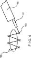
特に、図1から6に示されるように、本発明の第1実施形態の器具10は、セントラル・ルーメン14を含む可撓性チューブ12からなり、該セントラル・ルーメンには複数の固定部材16が受け入れられる。当業者は、チューブ12が、例えば、ステンレス鋼又は成型ポリマーのような生体親和の金属のコイルで構成されることを理解する。チューブ12は使用中の緊張及び圧縮の力に耐えるため軸方向に堅固であるが、同時に内視鏡18を介しての挿入の間チューブ12を曲げることが可能な程度の可撓性も有する。
In particular, as shown in FIGS. 1-6, the
チューブ12は、近接端に連結するハンドル(図示せず)及び遠位端24間を延長する。図3及び4に示されるように、チューブ12は、内視鏡18の作動チャンネルを通ることが可能な大きさを有する。
例えば、チューブ12の外径は6から9フレンチであることが望ましい。当業者は、チューブ12が例えば剛性ラパラスコープ(laparascope)又は観血療法に適用するために代替的により大きな外径で形成することや剛性材料で作ることも可能であることを理解する。
固定部材16は、ルーメン14内で互いに接し、固定部材のうち最も近接した固定部材16aの近接端に接する押出ピストン(図示せず)は、ルーメン14を通じて、ハンドルのアクチュエーターと連結するために延設される。アクチュエーター28の作動は、押出ピストンを、最も近接した固定部材16a及び遠位端24に向かって遠位で受け入れられる全ての固定部材16を移動させるルーメン14内へと、遠位に移動させる。
For example, the outer diameter of the
The
本発明の第1実施形態の各固定部材16は、先の尖った組織を貫通する遠位端30を含む。この遠位端30は、ルーメン14内に受け入れられる時、遠位開口部32と向かい合う。縫合糸34は固定部材16間で延長する。
この固定部材は、対応する各固定部材16のシャフト38の近接端に形成される小穴36を通過する。縫合糸34の遠位端は、固定部材のうちで最も遠位部材16bの小穴36に連結し、該小穴から残りの固定部材16の各小穴36を通じて遠位から近接へと順に連続して延長する。
縫合糸34の第2端部は、使用者が利用しやすいように、縫合糸は固定部材のうち最も近接した部材16aの小穴36及び、ルーメン14を介して、チューブ12の近接端から出て延長する。
当業者によって理解されるように、縫合糸34は、ポリグリコール酸やポリグリコール酸のような生分解性や生体吸収性が高い、生体親和材料で形成される。更に当業者は、縫合糸34の外側が、身体外の第1端部へと延長し、使用者が使い易いように、ルーメン14を通じ、各小穴36を通じかつルーメン14を通じてユーザが使い易い第2端部へと戻るように、代替として縫合糸34が固定部材のうち最も遠位部材16bの小穴を含む全ての小穴を通じて延長する。
Each
This fixing member passes through a
The second end of the suture 34 exits from the proximal end of the
As understood by those skilled in the art, the suture 34 is formed of a biocompatible material such as polyglycolic acid or polyglycolic acid that has high biodegradability and bioabsorbability. Further, those skilled in the art will appreciate that a second user-friendly second through the
図2で示されるように、各固定部材16は、腕状部40が図1に示される格納位置及び図2に示される展開位置間を回転できるように、ピン42でシャフト38と回転の中心となって連結した一組の格納式腕状部40を含む。
格納位置において、腕状部40は、固定部材16の直径がルーメン14の内径よりも小さくなるように、シャフトに沿って折り曲げられる。ルーメン14内にある間、腕状部40は、ルーメン14の内壁によって格納位置で維持される。
As shown in FIG. 2, each
In the retracted position, the
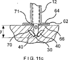
固定部材16がルーメン14から取り外されたとき、腕状部40は、図11aから図11cにより詳細に示される接触圧力機構13の制御下で展開して配置される。接触圧力機構13は、固定部材16の尖った遠位端30が組織と接触し、チューブ12が組織を貫通することを防ぐ時のみ腕状部40が配置されることを、また固定部材16が組織内に自身を十分に固定するために望ましい深さに配置されることを確実に行う。
特に、チューブ12の遠位端24に形成される接触圧力機構13は、一連の近接腕状部64の遠位端を、対応する遠位の腕状部66の近接端へと接続する第1ヒンジ62を有する蛇腹部60を含む。第2ヒンジ68は、遠位の腕状部66の少なくとも一部の遠位端を対応する固定部材グリップ・アームへと接続する。第3ヒンジ71は、近接の腕状部66の近接端をチューブ12の本体に接続する。
When the
In particular, the
図11aで示すように、接触圧力機構13は、組織と接触していない最初の位置では、近位アーム64、遠位アーム66、グリップ・アーム68は実質的にチューブ12の外表面と平行であるため、バイアスがかけられる。図11bで示すように、遠位端24が組織と接触するため、チューブ12が遠位に向かって動くとき、収縮可能アーム40を収縮された状態に保つために、収縮可能アーム40に接するグリップ・アームの端と共に、チューブ12の内側で放射状に内側に向けてられるようにして、それぞれのグリップ・アーム68の外表面が組織の表面に置かれるため、グリップ・アーム68は、内側に回される。この時点で、近位アーム64と遠位アーム66は、第1ヒンジ62が、チューブ12から放射状に外側に向かって、図11cで示すように、遠位アーム66の外表面が組織表面に横たわる状態になるまで動くため、第1ヒンジ62の辺りで回転される。
As shown in FIG. 11 a, in the initial position where the
更に、接触圧力機構13は、図11aの最初の構成から図11cの最後の構成へと、放射状に拡げられ、軸方向に縮められるにつれて、チューブ12の遠位開口部は、遠位端30が組織を貫通するため、最遠位固定部16の遠位端30に接するように、近位に向かって動く。
該遠位端30が組織内へ更に押されるにしたがい、グリップ・アーム68は、収縮可能アーム40の近位端がグリップ・アーム68を遠位に向かって通過するまで、収縮された状態で収縮可能アーム40を収容する。この時点までに、収縮可能アーム40の一部が、組織内に受け入れられ、組織は、使用者が該アームを展開するまで、該アームを収縮された状態で収容する(例えば収縮可能アーム40の近位端と組織との接触が、該アームを放射状に外側に向けて展開された構造になるように引き抜くように、固定部材16を近位に向けて引くことにより)。当業者は、バイアスがかけられていない状態で、完全に延ばされた構成である場合、蛇腹部60の長さYは、該アーム40がグリップ・アーム70によって取り外された時、遠位端30の組織内における深さYと、略等しいことを理解する。
In addition, as the
As the
当業者は、固定部材16が、例えば合金金属、合成プラスティック、セラミック等を含む生物吸収可能、生物分解可能、もしくは生物共存可能な物質で形成され、例えば固定部材16はチタンで形成されても構わないことを理解することができる。
One skilled in the art will recognize that the
当業者は操作において、内視鏡18が例えば内視鏡的粘膜切除術もしくはPUD損傷によって生じた開口部を塞ぐように、器官内の開口部Oに面して位置づけられ、チューブ12が内視鏡18の作動チャンネルへ挿入され、内視鏡18の遠位端に向かって進められることを理解する。チューブ12は、次に内視鏡18の遠位端の外へ、開口部Oと面した最遠位固定部材16bのための望ましい位置に向かって進む。第1固定部材16のための望ましい配置場所は、好ましくは、開口部Oの最遠位端に隣接して選択される。使用者は、次に、チューブ12の遠位端24の外側へ向けて、望ましい位置の組織の内側へ向けて、最遠位固定部材16bを操縦することにより、遠位に向けて押出ピストン26をルーメン14の中に向かって動かし、アクチュエーター28を操作する。
一度、最遠位固定部材16bの先端30が望ましい深さまで、組織へ貫通すると、接触圧力機構13は望ましい局所の組織内の適所で、固定部材16bを停止させるように、アーム40を展開させるように作動する。使用者は、次に、第2固定部材16の1つのための望ましい位置に隣接したチューブ12の遠位端24の位置を変える。
使用者は、好ましくは、固定部材16が、使用者が従来の縫合において針を通した位置と同様に、開口部Oの交互の側面に置くようにして位置を選択する。図4で示すように縫合糸34は、固定部材16bの小さい穴36を通って、第2固定部材16の1つの小さな穴まで延長する。
使用者は、次に最近位固定部材16aが、首尾よく配置されるまで、各固定部材16を望ましい位置に置くようにして、この過程を繰り返す。次に、使用者は、図5で示すように、固定部材16が、共に埋め込まれている範囲内で、固定部材16と組織を引き寄せ、開口部を閉じるように、チューブ12から近位に向かって、最遠位固定部材66bの小さい穴36と合わせられた遠位端の縫合糸34を引く。
One skilled in the art will operate in such a way that the
Once the
The user preferably selects the position so that the
The user repeats this process, with each securing
本発明の第2実施例に関するシステム100を、図7から図12に示す。システム100はカテーテル106が104の内側に滑るように受け入れられ、カテーテル104は102の内側に滑るように受け入れられる状態で、3つの収容されたカテーテル102、104、及び106を含む。
チューブ12と同様に、カテーテル102は、例えばステンレス鋼もしくは成型されたポリマーのような生物共存可能金属コイルから構成することができる。カテーテル102は、内視鏡の作動チャンネルを通して、その挿入時のために曲げることができるように、可撓性に富み、その近位端と結合されたハンドルと遠位端102aの間を延長する。固定クリップ108はカテーテル104と102の遠位端104aと102aにそれぞれ面している固定クリップ108の組織に貫通する遠位端109と共に、カテーテル104の内側に受け入れられる。図7の状態1)と2)上の最近位固定クリップ108bで示されるように、カテーテル104の内側にある間、カテーテル104のルーメン104bの内表面が、突出部材110を、それぞれの固定クリップ108に沿って、後方に折り曲げられ収縮された構成に保つ。
これらの突出部材110は、固定クリップ108の本体から外側に放射状にバイアスがかけられる。図7の状態1)上の最遠位固定クリップ108aと状態4)上の最近位固定部材108bのように、これは、固定クリップ108の1つが、カテーテル104の遠位端104aを超えて、遠位の方向へ進んだ時、突出部材110が、カテーテル102の内表面に接触するまで、外側に押しているためである。
A
Similar to the
These protruding
次に、固定クリップ108がカテーテル102の遠位端12aを超えて、更に進められる時、図7の状態2)から4)で示すように、突出部材110は延長された状態まで完全に展開する。縫合糸112は、最遠位固定クリップ108aの近位端と連結し、最近位固定クリップ108bの近位端を通るまで、そこから後方に位置する固定クリップ108の近位端へ延長する。当業者は、図は実施例のため、2つの固定クリップ108を示すだけだが、最遠位端と最近位固定クリップ108a、及び108bの間それぞれ、任意の数の固定クリップ108を含むことができることを理解できる。
Next, when the
図9、10、13で示すように、縫合糸112は、最近位固定クリップ108bからカテーテル106の遠位端106aの辺りを包むように通り、そこで形成されたルーメン106bを通って、縫合糸112が使用者に確認できる場所にある内視鏡の近位端まで延長する。また、縫合切断表面106cは、カテーテル106の遠位端106aで形成される。カテーテル102、104及び106が内視鏡に挿入される前に、結び目114は、カテーテル106の端付近で形成され、図12で示すように、ピン116aと116bによって、適切な場所に収容される。一度、最近位固定クリップ108bが望ましい位置の組織内へ挿入されると、使用者は、ピン116aと116bをその辺りで放すことにより、カテーテル104の遠位端104aを超えてカテーテル106を進める。ピン116a及び116bは、カテーテル106から取り除かれるので(例えば、縫合糸112が遠位に向かって、ピン116a及び116bにかける力によって)、結び目114は遠位端106aから放たれる。縫合糸112は、次に、結び目114を締めるために、近位に向かってカテーテル106から引っ張られ、遠位端106aは、次に、縫合糸112が、固定クリップ108と、開口部を閉じるために、共に埋め込まれた範囲内の組織を引くために十分な張り具合になるまで、縫合糸112に沿って、結び目114を遠位に向かって押すために用いられる。当業者は、操作者が望むなら、例えば引き用ワイヤー等を含む任意の数の装置を、ピン116を取り外すために利用することができることを理解する。
As shown in FIGS. 9, 10, and 13, the
更に明確には、カテーテル104は、遠位端104aで形成されたピン118を含む。該ピン118は、カテーテル104の軸から離れて回転するために、バイアスがかけられた収縮可能アーム120に搭載されている。カテーテル104がカテーテル102の内側で受け入れられる時、アーム120は、カテーテル104の残りの部分と共に、一直線になる。この状態の時、ピン118は、その時点でカテーテル102の内側の最遠位部である固定クリップ108bと結合される。カテーテル102の内側にある稼働するカテーテル104が、最遠位固定クリップ108を関連してそこへ動かすので、ピン118は、固定クリップ118の近位端の近くで、形成された一致する開口部112の内側に受け入れられる。遠位端104aが図8で示すように遠位端102aを超えて、遠位に向かって進む時、収縮可能アーム120は、固定クリップ108をカテーテル104から切り離すことにより、開口部122からピン118を除くために、外側に向かって回転する。
More specifically, the
操作において、使用者はカテーテル102、該カテーテル内に受け入れられるカテーテル104や106を内視鏡の作動チャンネルを通して開口部を塞ぐように通し、遠位端102aを第1固定クリップ108のための望ましい位置に置く。使用者は、次に、最遠位固定クリップ108の突出部材110がカテーテル104によって放され、カテーテル104を近位に向けてカテーテル102の中へ引く。遠位端102aが望ましい位置で、組織との接触部に置かれるため、カテーテル106は、次に、最遠位固定クリップ108aの先端109を組織内に動かすため、カテーテル104を通って遠位に向かって進められる。この時点で、突出部材110は完全に展開し、望ましい位置において、組織の中へ進んでいる固定クリップ108aを固定する。使用者は、次に、収縮可能アーム120が、開口部122からピン118を取り除くために外側に回転するので、カテーテル120と関連してカテーテル102を近位に向かって引く。使用者は、次に、ピン118が次の(その時点での最遠位の)固定クリップ108の中の、開口部122に入るまで、カテーテル106を遠位に向かって、カテーテル104の内側に動かせている間に、カテーテル102と104を固定クリップ108から放し、近位に向かって引き出し、アーム120をカテーテル104の残りと一直線上に戻すために、カテーテル140を近位に向かってカテーテル102の中へ引き出す。その後、使用者は、カテーテル102を次の固定クリップ108のための望ましい位置へ動かし、全ての固定クリップ108が望ましい位置の組織内へ埋め込まれるまで、この過程を繰り返す。
In operation, the user passes
この時点で、縫合糸112は最遠位固定クリップ108aから後で続く各固定クリップ108を通り、最近位固定クリップ108bまで、更に、そこから結び目114まで延長する。カテーテル106は、上記のようにピン116aと116bが放されるように、ピン116aと116bから結び目114を放すために、遠位端104aと102aを超えて進められる。使用者は、開口部をふさぐために、固定クリップ108を共に引き出し、開口部付近の組織を同時に引くように、縫合糸112を近位に向かってカテーテル106の中へ引き出す。使用者は、次に、結び目114を締め、固定クリップを適切な位置に保つために、結び目114を最近位固定クリップ108bの近位端に対して突き、縫合糸112を切るために縫合切断表面106aを用いる。使用者は、次にカテーテル106をカテーテル102及び104の中へ引き出し、装置100を体から引き出す。
At this point, the
図14は、本発明の他の第1実施形態の固定部材208を示す。該固定部材208は、組織貫通遠位先端212を延長するシャフト210及び該シャフト210から外向きに延長する突出部材214を含む。
小穴216は、シャフトの近くに形成され、縫合糸218は、固定部材208を他の固定部材へ連結するために延長する。
FIG. 14 shows a fixing
The
図15は、本発明の他の第2実施形態の固定部材308を示す。固定部材308は、組織貫通遠位先端312に延長するシャフト310及び該シャフト310に連結される突出部材314を含む。小穴312はシャフトの近くに形成され、その結果縫合糸314は、固定部材308を他の固定部材に連結するために延長する。
突出部材314は、最初にシャフト310に沿って折り畳まれる(すなわち、挿入装置を介した固定部材を挿入する間、及び組織を貫通する間)。しかしながら、一度先端312が、突出部材314の近端が組織内に埋め込まれる範囲で組織を貫通すると、固定部材308を組織の表面の方へ引き寄せることは、該突出部材がシャフト310から離れて外向きに広がり、該組織内に固定部材308を固定する。
FIG. 15 shows a fixing
The protruding
図16は、本発明の他の第3実施形態の固定部材408を示す。該固定部材408は、端部412を互いにその間に受け入れられる組織を掴むようにするために、バイアスがかけられたバネ状部材414に連結された第1及び第2組織グリップ・エンド412を含む。図15において、このバイアスは、スプリング部材414がループ416を形成するために曲げることにより生じる。
縫合糸418は、固定部材408を他の固定部材に連結するためのループ416を介して延長する。
FIG. 16 shows a fixing
The
図17は、本発明の他の第4実施形態の固定部材508を示す。固定部材508は、ループ516を形成するためにバネ状部514を曲げることにより、端部512を互いにその間に受け入れられる組織を掴むようにするために、バイアスがかけられたバネ状部514に連結される第1及び第2組織グリップ・エンド512を含む。
縫合糸518は、固定部材508を他の固定部材に連結するためのループ516を介して延長する。更に、固定部材508は隣接部材520を含み、該隣接部材は、端部512が互いに最小隙間に達した時、接触する。
この最小隙間は、端部512が共に接近しグリップされた組織を切断することを隣接部材520が防ぐことによって維持される。
FIG. 17 shows a fixing
The
This minimum clearance is maintained by the
上記の実施形態は例示の目的のみであり、これら実施形態の明らかに多くの修正が、添付の請求項のみによって限定される本発明の技術の範囲で考慮される。 The above embodiments are for illustrative purposes only, and obviously many modifications of these embodiments are considered within the scope of the present invention, which is limited only by the appended claims.
Claims (15)
組織を貫通する遠位端から縫合糸を受け入れる近端部まで延長するシャフト及び、収縮可能アームが該シャフトに対して折り畳まれる挿入構成と、収縮可能アームがシャフトから離れて延長するグリップ構成との間で移動可能な収縮可能アームを含む、前記第1カテーテル内に受け入れられる複数の固定部材であって、該接触圧力機構は、該第1固定部材の遠位端が該組織を貫通するときに、該第1固定部材の該収縮可能アームを該挿入構成から取り外す、複数の固定部材と、
組織内で固定するために、第1カテーテルの外側に、固定部材の1つである最遠位部を駆動するための駆動部材を前記第1カテーテルから離して進め、前記固定部材を、該第1カテーテルを貫通し、離して進める、前記第1カテーテルを貫通して該カテーテルの近端部へ延長する駆動部材と、
縫合糸を受け入れる前記固定部材の近端部の間で延長する一本の縫合糸と、
を備える、患者の内臓の開口部を縫合するための装置。A first catheter for insertion through an operating channel of an endoscope into a sealing opening, wherein the distal end of the first catheter includes a contact pressure mechanism, and the contact pressure mechanism A first hinge formed at a predetermined distance from the distal end of one catheter and a second hinge formed near the first hinge, so that the distal end of the first catheter is tissue The first catheter is folded into a radially deployed configuration when contacting the first catheter; and
A shaft extending from a distal end penetrating tissue to a proximal end for receiving a suture; an insertion configuration in which the retractable arm is folded relative to the shaft; and a grip configuration in which the retractable arm extends away from the shaft. A plurality of anchoring members received within the first catheter, the retractor arm including a retractable arm movable between the contact pressure mechanism when the distal end of the first anchoring member penetrates the tissue A plurality of fixation members for removing the retractable arm of the first fixation member from the insertion configuration;
In order to fix in the tissue, a driving member for driving the most distal portion, which is one of the fixing members, is moved away from the first catheter outside the first catheter, and the fixing member is moved to the first catheter. A drive member extending through the first catheter and advanced away, extending through the first catheter to the proximal end of the catheter;
A suture extending between the proximal ends of the securing members for receiving the suture;
A device for suturing a visceral opening of a patient.
各固定部材が、組織貫通遠端部から縫合糸受け入れ近端部へ延長するシャフト、及び更に移動可能なように連結される収縮可能アームを含み、前記第1カテーテル内に受け入れられる複数の固定部材であって、該複数の固定部材のうちの少なくとも最初の固定部材の延長手段は、グリップ構成の方へ該収縮可能アームにバイアスをかけるバイアス部材を含み、該複数の固定部材のうちの少なくとも該最初の固定部材の収縮可能アームは、挿入構成において、該第1カテーテルの内壁と該収縮可能アームとの間の接触によって該第1カテーテル内に受け入れられる間に抑制される、複数の固定部材と、
組織内で固定するために、第1カテーテルの外側に、固定部材の1つである最遠位部を駆動するための駆動部材を前記第1カテーテルから離して進め、前記固定部材を、該第1カテーテルを貫通し、離して進める、前記第1カテーテルを貫通して該カテーテルの近端部へ延長する駆動部材であって、各固定部材の延長手段は、挿入構成から対応する固定部材の収縮可能アームを配置し、該収縮可能アームはシャフトに対しグリップ構成へ折り畳まれ、対応する固定部材が第1カテーテルから組織へ配置される時、収縮可能アームがシャフトから離れて延長する、駆動部材と、
縫合糸を受け入れる前記固定部材の近端部の間で延長する縫合糸の長さと、
を備える、患者の体内で組織を縫合するための装置。A first catheter for insertion through an operating channel of an endoscope, the distal end of the first catheter including a contact pressure mechanism including a first hinge and a second hinge, so that the contact A first catheter that is folded into a radially deployed configuration when the pressure mechanism is pressed against tissue ;
A plurality of fixation members received within the first catheter, each fixation member including a shaft extending from the tissue penetrating distal end to the suture receiving proximal end and a further movably connected retractable arm The at least first securing member extension means of the plurality of securing members includes a biasing member biasing the retractable arm toward a gripping configuration, and at least the securing members of the plurality of securing members. A plurality of fixation members, wherein the retractable arm of the initial fixation member is restrained in the insertion configuration while being received within the first catheter by contact between the inner wall of the first catheter and the retractable arm; ,
In order to fix in the tissue, a driving member for driving the most distal portion, which is one of the fixing members, is moved away from the first catheter outside the first catheter, and the fixing member is moved to the first catheter. A driving member that penetrates and separates one catheter and extends through the first catheter to the proximal end of the catheter, wherein the extension means of each fixing member is a contraction of the corresponding fixing member from the insertion configuration A retractable arm, wherein the retractable arm is folded into a grip configuration relative to the shaft, and the retractable arm extends away from the shaft when the corresponding fixation member is positioned from the first catheter to the tissue; ,
A suture length extending between the proximal ends of the securing members for receiving the suture;
A device for suturing tissue within a patient's body.
Applications Claiming Priority (3)
| Application Number | Priority Date | Filing Date | Title |
|---|---|---|---|
| US10/045,975 US7150750B2 (en) | 2002-01-10 | 2002-01-10 | Method and device for endoscopic suturing |
| US10/045,975 | 2002-01-10 | ||
| PCT/US2002/039579 WO2003059173A1 (en) | 2002-01-10 | 2002-12-11 | Device for endoscopic suturing |
Publications (3)
| Publication Number | Publication Date |
|---|---|
| JP2005514150A JP2005514150A (en) | 2005-05-19 |
| JP2005514150A5 JP2005514150A5 (en) | 2005-12-22 |
| JP4776881B2 true JP4776881B2 (en) | 2011-09-21 |
Family
ID=21940862
Family Applications (1)
| Application Number | Title | Priority Date | Filing Date |
|---|---|---|---|
| JP2003559343A Expired - Fee Related JP4776881B2 (en) | 2002-01-10 | 2002-12-11 | Device for endoscopic suturing |
Country Status (8)
| Country | Link |
|---|---|
| US (1) | US7150750B2 (en) |
| EP (1) | EP1463451B1 (en) |
| JP (1) | JP4776881B2 (en) |
| AT (1) | ATE455503T1 (en) |
| AU (1) | AU2002357154B2 (en) |
| CA (1) | CA2469495A1 (en) |
| DE (1) | DE60235201D1 (en) |
| WO (1) | WO2003059173A1 (en) |
Families Citing this family (166)
| Publication number | Priority date | Publication date | Assignee | Title |
|---|---|---|---|---|
| FR2768324B1 (en) | 1997-09-12 | 1999-12-10 | Jacques Seguin | SURGICAL INSTRUMENT FOR PERCUTANEOUSLY FIXING TWO AREAS OF SOFT TISSUE, NORMALLY MUTUALLY REMOTE, TO ONE ANOTHER |
| CA2293057C (en) | 1998-12-30 | 2008-04-01 | Depuy Orthopaedics, Inc. | Suture locking device |
| US7811296B2 (en) | 1999-04-09 | 2010-10-12 | Evalve, Inc. | Fixation devices for variation in engagement of tissue |
| US7563267B2 (en) | 1999-04-09 | 2009-07-21 | Evalve, Inc. | Fixation device and methods for engaging tissue |
| US6752813B2 (en) | 1999-04-09 | 2004-06-22 | Evalve, Inc. | Methods and devices for capturing and fixing leaflets in valve repair |
| ATE484241T1 (en) | 1999-04-09 | 2010-10-15 | Evalve Inc | METHOD AND DEVICE FOR HEART VALVE REPAIR |
| US8216256B2 (en) | 1999-04-09 | 2012-07-10 | Evalve, Inc. | Detachment mechanism for implantable fixation devices |
| US20040044350A1 (en) | 1999-04-09 | 2004-03-04 | Evalve, Inc. | Steerable access sheath and methods of use |
| WO2004100841A1 (en) | 1999-08-18 | 2004-11-25 | Intrinsic Therapeutics, Inc. | Devices and method for augmenting a vertebral disc nucleus |
| US8323341B2 (en) | 2007-09-07 | 2012-12-04 | Intrinsic Therapeutics, Inc. | Impaction grafting for vertebral fusion |
| US7972337B2 (en) | 2005-12-28 | 2011-07-05 | Intrinsic Therapeutics, Inc. | Devices and methods for bone anchoring |
| WO2002054978A2 (en) * | 1999-08-18 | 2002-07-18 | Intrinsic Orthopedics Inc | Devices and method for nucleus pulposus augmentation and retention |
| US6883520B2 (en) | 1999-08-18 | 2005-04-26 | Intrinsic Therapeutics, Inc. | Methods and apparatus for dynamically stable spinal implant |
| US7717961B2 (en) | 1999-08-18 | 2010-05-18 | Intrinsic Therapeutics, Inc. | Apparatus delivery in an intervertebral disc |
| US7998213B2 (en) | 1999-08-18 | 2011-08-16 | Intrinsic Therapeutics, Inc. | Intervertebral disc herniation repair |
| US8632590B2 (en) * | 1999-10-20 | 2014-01-21 | Anulex Technologies, Inc. | Apparatus and methods for the treatment of the intervertebral disc |
| US6524317B1 (en) | 1999-12-30 | 2003-02-25 | Opus Medical, Inc. | Method and apparatus for attaching connective tissues to bone using a knotless suture anchoring device |
| US7220266B2 (en) | 2000-05-19 | 2007-05-22 | C. R. Bard, Inc. | Tissue capturing and suturing device and method |
| US6770076B2 (en) * | 2001-02-12 | 2004-08-03 | Opus Medical, Inc. | Method and apparatus for attaching connective tissues to bone using a knotless suture anchoring device |
| US8657854B2 (en) | 2001-02-12 | 2014-02-25 | Arthrocare Corporation | Knotless suture anchoring device having deforming section to accommodate sutures of various diameters |
| US6780198B1 (en) | 2001-12-06 | 2004-08-24 | Opus Medical, Inc. | Bone anchor insertion device |
| US7048754B2 (en) | 2002-03-01 | 2006-05-23 | Evalve, Inc. | Suture fasteners and methods of use |
| CN100479768C (en) * | 2002-08-23 | 2009-04-22 | 科威诺中心有限公司 | Anchoring device and implementation thereof |
| US7343920B2 (en) * | 2002-12-20 | 2008-03-18 | Toby E Bruce | Connective tissue repair system |
| CN1822794B (en) | 2003-05-16 | 2010-05-26 | C.R.巴德有限公司 | Single intubation, multi-stitch endoscopic suturing system |
| US10646229B2 (en) | 2003-05-19 | 2020-05-12 | Evalve, Inc. | Fixation devices, systems and methods for engaging tissue |
| JP4145200B2 (en) * | 2003-06-06 | 2008-09-03 | オリンパス株式会社 | Suture device |
| US7255675B2 (en) * | 2004-03-23 | 2007-08-14 | Michael Gertner | Devices and methods to treat a patient |
| CA2566666C (en) | 2004-05-14 | 2014-05-13 | Evalve, Inc. | Locking mechanisms for fixation devices and methods of engaging tissue |
| US20060020277A1 (en) * | 2004-07-20 | 2006-01-26 | Gostout Christopher J | Gastric reshaping devices and methods |
| KR100551740B1 (en) | 2004-07-26 | 2006-02-13 | 학교법인고려중앙학원 | Bead for stitching and apparatus for stitching internal organ using the same |
| US7635329B2 (en) | 2004-09-27 | 2009-12-22 | Evalve, Inc. | Methods and devices for tissue grasping and assessment |
| US8052592B2 (en) | 2005-09-27 | 2011-11-08 | Evalve, Inc. | Methods and devices for tissue grasping and assessment |
| US20230329700A1 (en) * | 2005-02-07 | 2023-10-19 | Stryker Corporation | System And Method For All-Inside Suture Fixation For Implant Attachment And Soft Tissue Repair |
| EP1855599B1 (en) | 2005-02-07 | 2016-06-08 | Ivy Sports Medicine, LLC. | System for all-inside suture fixation for implant attachment and soft tissue repair |
| US8128640B2 (en) | 2005-02-07 | 2012-03-06 | Ivy Sports Medicine LLC | System and method for all-inside suture fixation for implant attachment and soft tissue repair |
| EP2353494B1 (en) | 2005-02-08 | 2014-07-30 | Koninklijke Philips N.V. | System for percutaneous glossoplasty |
| US8371307B2 (en) | 2005-02-08 | 2013-02-12 | Koninklijke Philips Electronics N.V. | Methods and devices for the treatment of airway obstruction, sleep apnea and snoring |
| US8096303B2 (en) | 2005-02-08 | 2012-01-17 | Koninklijke Philips Electronics N.V | Airway implants and methods and devices for insertion and retrieval |
| JP4669316B2 (en) * | 2005-04-25 | 2011-04-13 | 日本シャーウッド株式会社 | Organ fixture set |
| JP2007097778A (en) * | 2005-10-03 | 2007-04-19 | Ehime Univ | Broken hole reducing apparatus |
| US7815659B2 (en) | 2005-11-15 | 2010-10-19 | Ethicon Endo-Surgery, Inc. | Suture anchor applicator |
| US8491631B2 (en) * | 2006-01-30 | 2013-07-23 | Children's Medical Center Corporation | Tissue tack |
| JP4308830B2 (en) * | 2006-04-17 | 2009-08-05 | 医療法人社団隆風会 | Medical ring |
| ES2382813T3 (en) | 2006-04-28 | 2012-06-13 | Covidien Ag | Instrumental set for organopexy |
| US7815566B2 (en) * | 2006-07-20 | 2010-10-19 | Ethicon Endo-Surgery, Inc. | Methods for stabilizing and positioning an endoscope and surgical procedures |
| US8133258B2 (en) | 2006-08-03 | 2012-03-13 | Arthrocare Corporation | Method and apparatus for attaching connective tissues to bone using a knotless suture anchoring device |
| JP4584230B2 (en) * | 2006-11-14 | 2010-11-17 | オリンパスメディカルシステムズ株式会社 | Clip device |
| US8784439B1 (en) * | 2006-11-28 | 2014-07-22 | Stephen V. Ward | Percutaneous medical procedures and devices for closing vessels using mechanical closures |
| ATE514382T1 (en) * | 2006-11-30 | 2011-07-15 | Wilson Cook Medical Inc | FABRIC ANCHOR FOR SEAM CLOSURE OF PERFORATIONS |
| US7655004B2 (en) | 2007-02-15 | 2010-02-02 | Ethicon Endo-Surgery, Inc. | Electroporation ablation apparatus, system, and method |
| US8137381B2 (en) | 2007-04-25 | 2012-03-20 | Arthrocare Corporation | Knotless suture anchor having discrete polymer components and related methods |
| US7967741B2 (en) * | 2007-05-01 | 2011-06-28 | Ethicon Endo-Surgery, Inc. | Endoscopic guide device |
| US20090024144A1 (en) * | 2007-07-18 | 2009-01-22 | Zeiner Mark S | Hybrid endoscopic/laparoscopic device for forming serosa to serosa plications in a gastric cavity |
| JP5301544B2 (en) * | 2007-08-17 | 2013-09-25 | クック メディカル テクノロジーズ エルエルシー | Organ staple for closure of perforated purse string suture |
| US8579897B2 (en) | 2007-11-21 | 2013-11-12 | Ethicon Endo-Surgery, Inc. | Bipolar forceps |
| US20110196492A1 (en) * | 2007-09-07 | 2011-08-11 | Intrinsic Therapeutics, Inc. | Bone anchoring systems |
| US7963972B2 (en) * | 2007-09-12 | 2011-06-21 | Arthrocare Corporation | Implant and delivery system for soft tissue repair |
| US8771314B2 (en) * | 2007-09-28 | 2014-07-08 | Ethicon, Inc. | Surgical anchor device |
| US8480657B2 (en) | 2007-10-31 | 2013-07-09 | Ethicon Endo-Surgery, Inc. | Detachable distal overtube section and methods for forming a sealable opening in the wall of an organ |
| US20090112059A1 (en) | 2007-10-31 | 2009-04-30 | Nobis Rudolph H | Apparatus and methods for closing a gastrotomy |
| US9375287B2 (en) * | 2008-01-29 | 2016-06-28 | Covidien Lp | Target identification tool for intra-body localization |
| US8679003B2 (en) | 2008-05-30 | 2014-03-25 | Ethicon Endo-Surgery, Inc. | Surgical device and endoscope including same |
| US8771260B2 (en) | 2008-05-30 | 2014-07-08 | Ethicon Endo-Surgery, Inc. | Actuating and articulating surgical device |
| EP2282664A4 (en) * | 2008-06-03 | 2013-07-31 | Virtual Ports Ltd | A multi-components device, system and method for assisting minimally invasive procedures |
| US8906035B2 (en) | 2008-06-04 | 2014-12-09 | Ethicon Endo-Surgery, Inc. | Endoscopic drop off bag |
| US8403926B2 (en) | 2008-06-05 | 2013-03-26 | Ethicon Endo-Surgery, Inc. | Manually articulating devices |
| US8105343B2 (en) | 2008-06-30 | 2012-01-31 | Arthrocare Corporation | Independent suture tensioning and snaring apparatus |
| US8888792B2 (en) | 2008-07-14 | 2014-11-18 | Ethicon Endo-Surgery, Inc. | Tissue apposition clip application devices and methods |
| US8409200B2 (en) | 2008-09-03 | 2013-04-02 | Ethicon Endo-Surgery, Inc. | Surgical grasping device |
| US8163022B2 (en) | 2008-10-14 | 2012-04-24 | Anulex Technologies, Inc. | Method and apparatus for the treatment of the intervertebral disc annulus |
| US8157834B2 (en) | 2008-11-25 | 2012-04-17 | Ethicon Endo-Surgery, Inc. | Rotational coupling device for surgical instrument with flexible actuators |
| CA2746213A1 (en) * | 2008-12-09 | 2010-07-08 | Wilson-Cook Medical Inc. | Apparatus and methods for controlled release of tacking devices |
| US20100152539A1 (en) * | 2008-12-17 | 2010-06-17 | Ethicon Endo-Surgery, Inc. | Positionable imaging medical devices |
| WO2010081029A1 (en) | 2009-01-08 | 2010-07-15 | Rotation Medical, Inc. | Implantable tendon protection systems and related kits and methods |
| US8361066B2 (en) | 2009-01-12 | 2013-01-29 | Ethicon Endo-Surgery, Inc. | Electrical ablation devices |
| JP5219855B2 (en) * | 2009-01-27 | 2013-06-26 | Hoya株式会社 | Endoscopic suture device |
| US9179910B2 (en) | 2009-03-20 | 2015-11-10 | Rotation Medical, Inc. | Medical device delivery system and method |
| CA2763919C (en) | 2009-06-04 | 2017-05-23 | Rotation Medical, Inc. | Apparatus for fixing sheet-like materials to a target tissue |
| AU2010256414C1 (en) | 2009-06-04 | 2016-01-21 | Rotation Medical, Inc. | Methods and apparatus for deploying sheet-like materials |
| US8790369B2 (en) * | 2009-07-24 | 2014-07-29 | Depuy Mitek, Llc | Apparatus and method for repairing tissue |
| US20110098704A1 (en) | 2009-10-28 | 2011-04-28 | Ethicon Endo-Surgery, Inc. | Electrical ablation devices |
| US8608652B2 (en) | 2009-11-05 | 2013-12-17 | Ethicon Endo-Surgery, Inc. | Vaginal entry surgical devices, kit, system, and method |
| US8496574B2 (en) | 2009-12-17 | 2013-07-30 | Ethicon Endo-Surgery, Inc. | Selectively positionable camera for surgical guide tube assembly |
| US8353487B2 (en) | 2009-12-17 | 2013-01-15 | Ethicon Endo-Surgery, Inc. | User interface support devices for endoscopic surgical instruments |
| US9028483B2 (en) | 2009-12-18 | 2015-05-12 | Ethicon Endo-Surgery, Inc. | Surgical instrument comprising an electrode |
| US8506564B2 (en) | 2009-12-18 | 2013-08-13 | Ethicon Endo-Surgery, Inc. | Surgical instrument comprising an electrode |
| US20110178537A1 (en) | 2010-01-20 | 2011-07-21 | Whitman Michael P | Tissue repair implant and delivery device and method |
| US10058314B2 (en) | 2010-01-20 | 2018-08-28 | Micro Interventional Devices, Inc. | Tissue closure device and method |
| US10743854B2 (en) | 2010-01-20 | 2020-08-18 | Micro Interventional Devices, Inc. | Tissue closure device and method |
| US10959840B2 (en) | 2010-01-20 | 2021-03-30 | Micro Interventional Devices, Inc. | Systems and methods for affixing a prosthesis to tissue |
| US9980708B2 (en) | 2010-01-20 | 2018-05-29 | Micro Interventional Devices, Inc. | Tissue closure device and method |
| US9005198B2 (en) | 2010-01-29 | 2015-04-14 | Ethicon Endo-Surgery, Inc. | Surgical instrument comprising an electrode |
| US9198750B2 (en) | 2010-03-11 | 2015-12-01 | Rotation Medical, Inc. | Tendon repair implant and method of arthroscopic implantation |
| WO2011137252A1 (en) | 2010-04-29 | 2011-11-03 | Vinay Badhwar | Automatic suturing apparatus and methods of use |
| US20110306992A1 (en) | 2010-06-09 | 2011-12-15 | C.R. Bard, Inc. | Instruments for delivering transfascial sutures, transfascial suture assemblies, and methods of transfascial suturing |
| US20120143225A1 (en) * | 2010-07-06 | 2012-06-07 | Pavilion Medical Innovations | Endoscopic fascial closure devices and methods for using same |
| US10092291B2 (en) | 2011-01-25 | 2018-10-09 | Ethicon Endo-Surgery, Inc. | Surgical instrument with selectively rigidizable features |
| CA2825918C (en) | 2011-02-15 | 2018-08-07 | Rotation Medical, Inc. | Methods and apparatus for delivering and positioning sheet-like materials |
| WO2012145059A1 (en) | 2011-02-15 | 2012-10-26 | Rotation Medical, Inc. | Methods and apparatus for fixing sheet-like materials to a target tissue |
| US9254169B2 (en) | 2011-02-28 | 2016-02-09 | Ethicon Endo-Surgery, Inc. | Electrical ablation devices and methods |
| US9233241B2 (en) | 2011-02-28 | 2016-01-12 | Ethicon Endo-Surgery, Inc. | Electrical ablation devices and methods |
| US9314620B2 (en) | 2011-02-28 | 2016-04-19 | Ethicon Endo-Surgery, Inc. | Electrical ablation devices and methods |
| WO2012125785A1 (en) | 2011-03-17 | 2012-09-20 | Ethicon Endo-Surgery, Inc. | Hand held surgical device for manipulating an internal magnet assembly within a patient |
| WO2012126477A1 (en) | 2011-03-22 | 2012-09-27 | Herlev Hospital | Fastening device, related tools and methods |
| US9636101B2 (en) | 2011-09-01 | 2017-05-02 | Arthrocare Corporation | Bone anchor having an integrated stress isolator |
| US8945177B2 (en) | 2011-09-13 | 2015-02-03 | Abbott Cardiovascular Systems Inc. | Gripper pusher mechanism for tissue apposition systems |
| US9826972B2 (en) | 2011-10-24 | 2017-11-28 | C.R. Bard, Inc. | Instruments for delivering transfascial sutures, transfascial suture assemblies and methods of transfascial suturing |
| WO2013096224A1 (en) | 2011-12-19 | 2013-06-27 | Rotation Medical, Inc. | Fasteners for affixing sheet -like materials to bone or tissue |
| EP3403601A1 (en) | 2011-12-19 | 2018-11-21 | Rotation Medical, Inc. | Apparatus for forming pilot holes in bone and delivering fasteners therein for retaining an implant |
| US9107661B2 (en) | 2011-12-19 | 2015-08-18 | Rotation Medical, Inc. | Fasteners and fastener delivery devices for affixing sheet-like materials to bone or tissue |
| AU2012369140B2 (en) | 2011-12-19 | 2016-11-10 | Rotation Medical, Inc. | Fasteners for affixing sheet -like materials to bone or tissue |
| WO2013101638A1 (en) | 2011-12-29 | 2013-07-04 | Rotation Medical, Inc. | Methods and apparatus for delivering and positioning sheet -like materials in surgery |
| WO2013101641A2 (en) | 2011-12-29 | 2013-07-04 | Rotation Medical, Inc. | Anatomical location markers and methods of use in positioning sheet-like materials during surgery |
| WO2013101640A1 (en) | 2011-12-29 | 2013-07-04 | Rotation Medical, Inc. | Guidewire having a distal fixation member for delivering and positioning sheet-like materials in surgery |
| US9107654B2 (en) * | 2012-01-05 | 2015-08-18 | Cook Medical Technologies Llc | Attachment device for tissue approximation and retraction |
| US9023083B2 (en) | 2012-01-27 | 2015-05-05 | Arthrocare Corporation | Method for soft tissue repair with free floating suture locking member |
| US9364210B2 (en) | 2012-01-27 | 2016-06-14 | Arthrocare Corporation | Biased wedge suture anchor and method for soft tissue repair |
| US9034014B2 (en) | 2012-01-27 | 2015-05-19 | Arthrocare Corporation | Free floating wedge suture anchor for soft tissue repair |
| US9226742B2 (en) | 2012-01-27 | 2016-01-05 | Arthrocare Corporation | Restricted wedge suture anchor and method for soft tissue repair |
| US9198649B2 (en) | 2012-01-27 | 2015-12-01 | Arthrocare Corporation | Rotating locking member suture anchor and method for soft tissue repair |
| US9855028B2 (en) | 2012-04-06 | 2018-01-02 | Arthrocare Corporation | Multi-suture knotless anchor for attaching tissue to bone and related method |
| US9427255B2 (en) | 2012-05-14 | 2016-08-30 | Ethicon Endo-Surgery, Inc. | Apparatus for introducing a steerable camera assembly into a patient |
| US9078662B2 (en) | 2012-07-03 | 2015-07-14 | Ethicon Endo-Surgery, Inc. | Endoscopic cap electrode and method for using the same |
| US9545290B2 (en) | 2012-07-30 | 2017-01-17 | Ethicon Endo-Surgery, Inc. | Needle probe guide |
| US9572623B2 (en) | 2012-08-02 | 2017-02-21 | Ethicon Endo-Surgery, Inc. | Reusable electrode and disposable sheath |
| US10314649B2 (en) | 2012-08-02 | 2019-06-11 | Ethicon Endo-Surgery, Inc. | Flexible expandable electrode and method of intraluminal delivery of pulsed power |
| US9277957B2 (en) | 2012-08-15 | 2016-03-08 | Ethicon Endo-Surgery, Inc. | Electrosurgical devices and methods |
| AU2014209124A1 (en) | 2013-01-28 | 2015-09-17 | Cartiva, Inc. | Systems and methods for orthopedic repair |
| US9737294B2 (en) * | 2013-01-28 | 2017-08-22 | Cartiva, Inc. | Method and system for orthopedic repair |
| US10098527B2 (en) | 2013-02-27 | 2018-10-16 | Ethidcon Endo-Surgery, Inc. | System for performing a minimally invasive surgical procedure |
| EP3957252A1 (en) * | 2013-08-30 | 2022-02-23 | Bioventrix, Inc. | Heart anchor positioning devices, methods, and systems for treatment of congestive heart failure and other conditions |
| CN103536328B (en) * | 2013-10-31 | 2016-04-06 | 王东 | Rapid tissue perforation suture instrument |
| CN103536327A (en) * | 2013-10-31 | 2014-01-29 | 王东 | Combined tissue perforation suturing instrument |
| JP6227432B2 (en) * | 2014-01-31 | 2017-11-08 | 住友ベークライト株式会社 | Repeated organ fixation device |
| US9572666B2 (en) | 2014-03-17 | 2017-02-21 | Evalve, Inc. | Mitral valve fixation device removal devices and methods |
| US10390943B2 (en) | 2014-03-17 | 2019-08-27 | Evalve, Inc. | Double orifice device for transcatheter mitral valve replacement |
| WO2015143366A1 (en) | 2014-03-21 | 2015-09-24 | Boston Scientific Scimed, Inc. | Devices and methods for lumen occlusion |
| US20150282790A1 (en) * | 2014-04-08 | 2015-10-08 | Boston Scientific Scimed, Inc. | Endoscopic closure device |
| WO2015172052A1 (en) | 2014-05-09 | 2015-11-12 | Rotation Medical, Inc. | Medical implant delivery system for sheet-like implant |
| WO2016028898A2 (en) * | 2014-08-21 | 2016-02-25 | Boston Scientific Scimed, Inc. | Anchors and cinching for tissue opposition |
| EP3215026B1 (en) | 2014-11-04 | 2023-10-25 | Rotation Medical, Inc. | Medical implant delivery system |
| US10675019B2 (en) | 2014-11-04 | 2020-06-09 | Rotation Medical, Inc. | Medical implant delivery system and related methods |
| CA2965853A1 (en) | 2014-11-04 | 2016-05-12 | Rotation Medical, Inc. | Medical implant delivery system and related methods |
| US10188392B2 (en) | 2014-12-19 | 2019-01-29 | Abbott Cardiovascular Systems, Inc. | Grasping for tissue repair |
| US10524912B2 (en) | 2015-04-02 | 2020-01-07 | Abbott Cardiovascular Systems, Inc. | Tissue fixation devices and methods |
| CA2983341A1 (en) | 2015-05-06 | 2016-11-10 | Rotation Medical, Inc. | Medical implant delivery system and related methods |
| US10265156B2 (en) | 2015-06-15 | 2019-04-23 | Rotation Medical, Inc | Tendon repair implant and method of implantation |
| US10376673B2 (en) | 2015-06-19 | 2019-08-13 | Evalve, Inc. | Catheter guiding system and methods |
| US10238494B2 (en) | 2015-06-29 | 2019-03-26 | Evalve, Inc. | Self-aligning radiopaque ring |
| US10667815B2 (en) | 2015-07-21 | 2020-06-02 | Evalve, Inc. | Tissue grasping devices and related methods |
| US10413408B2 (en) | 2015-08-06 | 2019-09-17 | Evalve, Inc. | Delivery catheter systems, methods, and devices |
| US10238495B2 (en) | 2015-10-09 | 2019-03-26 | Evalve, Inc. | Delivery catheter handle and methods of use |
| US10758228B2 (en) | 2015-11-03 | 2020-09-01 | Rotation Medical, Inc. | Fastener delivery system and related methods |
| US10314689B2 (en) | 2015-12-31 | 2019-06-11 | Rotation Medical, Inc. | Medical implant delivery system and related methods |
| US10932769B2 (en) | 2016-05-26 | 2021-03-02 | Ivy Sports Medicine, Llc | System and method for all-inside suture fixation for implant attachment and soft tissue repair |
| US10736632B2 (en) | 2016-07-06 | 2020-08-11 | Evalve, Inc. | Methods and devices for valve clip excision |
| US11071564B2 (en) | 2016-10-05 | 2021-07-27 | Evalve, Inc. | Cardiac valve cutting device |
| US10363138B2 (en) | 2016-11-09 | 2019-07-30 | Evalve, Inc. | Devices for adjusting the curvature of cardiac valve structures |
| US10398553B2 (en) | 2016-11-11 | 2019-09-03 | Evalve, Inc. | Opposing disk device for grasping cardiac valve tissue |
| US10426616B2 (en) | 2016-11-17 | 2019-10-01 | Evalve, Inc. | Cardiac implant delivery system |
| US10779837B2 (en) | 2016-12-08 | 2020-09-22 | Evalve, Inc. | Adjustable arm device for grasping tissues |
| US10314586B2 (en) | 2016-12-13 | 2019-06-11 | Evalve, Inc. | Rotatable device and method for fixing tricuspid valve tissue |
| US11065119B2 (en) | 2017-05-12 | 2021-07-20 | Evalve, Inc. | Long arm valve repair clip |
| AU2018380146B2 (en) | 2017-12-07 | 2021-04-01 | Rotation Medical, Inc. | Medical implant delivery system and related methods |
| WO2022212980A1 (en) | 2021-03-31 | 2022-10-06 | Pamarope Pty Limited | Pessary system and method for pelvic floor ligament support |
Citations (2)
| Publication number | Priority date | Publication date | Assignee | Title |
|---|---|---|---|---|
| US5891168A (en) * | 1997-01-31 | 1999-04-06 | Thal; Raymond | Process for attaching tissue to bone using a captured-loop knotless suture anchor assembly |
| WO2001080746A1 (en) * | 2000-04-20 | 2001-11-01 | Co.Don Ag | Method and device for attaching and/or joining tissue or tissue-like materials to a support |
Family Cites Families (10)
| Publication number | Priority date | Publication date | Assignee | Title |
|---|---|---|---|---|
| US5437680A (en) * | 1987-05-14 | 1995-08-01 | Yoon; Inbae | Suturing method, apparatus and system for use in endoscopic procedures |
| US5207679A (en) * | 1991-09-26 | 1993-05-04 | Mitek Surgical Products, Inc. | Suture anchor and installation tool |
| US5242456A (en) * | 1991-11-21 | 1993-09-07 | Kensey Nash Corporation | Apparatus and methods for clamping tissue and reflecting the same |
| US5484451A (en) | 1992-05-08 | 1996-01-16 | Ethicon, Inc. | Endoscopic surgical instrument and staples for applying purse string sutures |
| US5464426A (en) | 1993-05-14 | 1995-11-07 | Bonutti; Peter M. | Method of closing discontinuity in tissue |
| US5662654A (en) * | 1995-06-14 | 1997-09-02 | Incont, Inc. | Bone anchor, insertion tool and surgical kit employing same |
| US5810848A (en) | 1996-08-21 | 1998-09-22 | Hayhurst; John O. | Suturing system |
| US6572629B2 (en) * | 2000-08-17 | 2003-06-03 | Johns Hopkins University | Gastric reduction endoscopy |
| US6447524B1 (en) * | 2000-10-19 | 2002-09-10 | Ethicon Endo-Surgery, Inc. | Fastener for hernia mesh fixation |
| IL140470A0 (en) | 2000-12-19 | 2002-02-10 | Friedman Shalom | Suturing system |
-
2002
- 2002-01-10 US US10/045,975 patent/US7150750B2/en not_active Expired - Lifetime
- 2002-12-11 JP JP2003559343A patent/JP4776881B2/en not_active Expired - Fee Related
- 2002-12-11 EP EP02806453A patent/EP1463451B1/en not_active Expired - Lifetime
- 2002-12-11 CA CA002469495A patent/CA2469495A1/en not_active Abandoned
- 2002-12-11 AU AU2002357154A patent/AU2002357154B2/en not_active Ceased
- 2002-12-11 AT AT02806453T patent/ATE455503T1/en not_active IP Right Cessation
- 2002-12-11 WO PCT/US2002/039579 patent/WO2003059173A1/en active Application Filing
- 2002-12-11 DE DE60235201T patent/DE60235201D1/en not_active Expired - Lifetime
Patent Citations (2)
| Publication number | Priority date | Publication date | Assignee | Title |
|---|---|---|---|---|
| US5891168A (en) * | 1997-01-31 | 1999-04-06 | Thal; Raymond | Process for attaching tissue to bone using a captured-loop knotless suture anchor assembly |
| WO2001080746A1 (en) * | 2000-04-20 | 2001-11-01 | Co.Don Ag | Method and device for attaching and/or joining tissue or tissue-like materials to a support |
Also Published As
| Publication number | Publication date |
|---|---|
| US20030130669A1 (en) | 2003-07-10 |
| JP2005514150A (en) | 2005-05-19 |
| CA2469495A1 (en) | 2003-07-24 |
| EP1463451A1 (en) | 2004-10-06 |
| EP1463451B1 (en) | 2010-01-20 |
| DE60235201D1 (en) | 2010-03-11 |
| AU2002357154A1 (en) | 2003-07-30 |
| US7150750B2 (en) | 2006-12-19 |
| ATE455503T1 (en) | 2010-02-15 |
| AU2002357154B2 (en) | 2007-11-29 |
| WO2003059173A1 (en) | 2003-07-24 |
Similar Documents
| Publication | Publication Date | Title |
|---|---|---|
| JP4776881B2 (en) | Device for endoscopic suturing | |
| JP7235811B2 (en) | Device for approximating multiple tissue edges | |
| EP1933720B1 (en) | Vascular opening edge eversion apparatuses | |
| US10111664B2 (en) | Closure system and methods of use | |
| JP4660714B2 (en) | Endoscopic tissue acquisition system | |
| EP1143861B1 (en) | Apparatus for compressing body tissue | |
| US9579091B2 (en) | Closure system and methods of use | |
| US20060106405A1 (en) | Systems and methods for delivering fastener to opposed tissue structures | |
| CN111655172B (en) | Hemostatic clamp | |
| WO2005096958A2 (en) | Endoscopic fastening system with multiple fasteners | |
| JP2004511275A (en) | Wound site management and wound closure devices | |
| US20110238090A1 (en) | Methods and devices for delivering sutures in tissue | |
| JP2012507358A (en) | Method and apparatus for applying multiple suture anchors | |
| US20090054913A1 (en) | Blind rivet for adapting biological tissue and device for setting the same, in particular through the instrument channel of an endoscope | |
| WO2008137531A2 (en) | Endoscopic guide device | |
| US20120071901A1 (en) | Methods and devices for delivering sutures in tissue | |
| EP2271270B1 (en) | Endoscopic stapling device |
Legal Events
| Date | Code | Title | Description |
|---|---|---|---|
| A711 | Notification of change in applicant |
Free format text: JAPANESE INTERMEDIATE CODE: A711 Effective date: 20050309 |
|
| A521 | Request for written amendment filed |
Free format text: JAPANESE INTERMEDIATE CODE: A821 Effective date: 20050309 |
|
| A621 | Written request for application examination |
Free format text: JAPANESE INTERMEDIATE CODE: A621 Effective date: 20051020 |
|
| A977 | Report on retrieval |
Free format text: JAPANESE INTERMEDIATE CODE: A971007 Effective date: 20081212 |
|
| A131 | Notification of reasons for refusal |
Free format text: JAPANESE INTERMEDIATE CODE: A131 Effective date: 20081217 |
|
| A521 | Request for written amendment filed |
Free format text: JAPANESE INTERMEDIATE CODE: A821 Effective date: 20090105 |
|
| RD02 | Notification of acceptance of power of attorney |
Free format text: JAPANESE INTERMEDIATE CODE: A7422 Effective date: 20090105 |
|
| RD04 | Notification of resignation of power of attorney |
Free format text: JAPANESE INTERMEDIATE CODE: A7424 Effective date: 20090120 |
|
| A131 | Notification of reasons for refusal |
Free format text: JAPANESE INTERMEDIATE CODE: A131 Effective date: 20090717 |
|
| A601 | Written request for extension of time |
Free format text: JAPANESE INTERMEDIATE CODE: A601 Effective date: 20091016 |
|
| A602 | Written permission of extension of time |
Free format text: JAPANESE INTERMEDIATE CODE: A602 Effective date: 20091023 |
|
| A521 | Request for written amendment filed |
Free format text: JAPANESE INTERMEDIATE CODE: A523 Effective date: 20091116 |
|
| A131 | Notification of reasons for refusal |
Free format text: JAPANESE INTERMEDIATE CODE: A131 Effective date: 20100323 |
|
| A601 | Written request for extension of time |
Free format text: JAPANESE INTERMEDIATE CODE: A601 Effective date: 20100622 |
|
| A602 | Written permission of extension of time |
Free format text: JAPANESE INTERMEDIATE CODE: A602 Effective date: 20100629 |
|
| A521 | Request for written amendment filed |
Free format text: JAPANESE INTERMEDIATE CODE: A523 Effective date: 20100712 |
|
| A02 | Decision of refusal |
Free format text: JAPANESE INTERMEDIATE CODE: A02 Effective date: 20110120 |
|
| A521 | Request for written amendment filed |
Free format text: JAPANESE INTERMEDIATE CODE: A523 Effective date: 20110519 |
|
| A911 | Transfer to examiner for re-examination before appeal (zenchi) |
Free format text: JAPANESE INTERMEDIATE CODE: A911 Effective date: 20110530 |
|
| TRDD | Decision of grant or rejection written | ||
| A01 | Written decision to grant a patent or to grant a registration (utility model) |
Free format text: JAPANESE INTERMEDIATE CODE: A01 Effective date: 20110622 |
|
| A01 | Written decision to grant a patent or to grant a registration (utility model) |
Free format text: JAPANESE INTERMEDIATE CODE: A01 |
|
| A61 | First payment of annual fees (during grant procedure) |
Free format text: JAPANESE INTERMEDIATE CODE: A61 Effective date: 20110629 |
|
| R150 | Certificate of patent or registration of utility model |
Ref document number: 4776881 Country of ref document: JP Free format text: JAPANESE INTERMEDIATE CODE: R150 Free format text: JAPANESE INTERMEDIATE CODE: R150 |
|
| FPAY | Renewal fee payment (event date is renewal date of database) |
Free format text: PAYMENT UNTIL: 20140708 Year of fee payment: 3 |
|
| R250 | Receipt of annual fees |
Free format text: JAPANESE INTERMEDIATE CODE: R250 |
|
| R250 | Receipt of annual fees |
Free format text: JAPANESE INTERMEDIATE CODE: R250 |
|
| R250 | Receipt of annual fees |
Free format text: JAPANESE INTERMEDIATE CODE: R250 |
|
| R250 | Receipt of annual fees |
Free format text: JAPANESE INTERMEDIATE CODE: R250 |
|
| R250 | Receipt of annual fees |
Free format text: JAPANESE INTERMEDIATE CODE: R250 |
|
| R250 | Receipt of annual fees |
Free format text: JAPANESE INTERMEDIATE CODE: R250 |
|
| LAPS | Cancellation because of no payment of annual fees |