JP4773788B2 - Remote copy control in storage system - Google Patents
Remote copy control in storage system Download PDFInfo
- Publication number
- JP4773788B2 JP4773788B2 JP2005283276A JP2005283276A JP4773788B2 JP 4773788 B2 JP4773788 B2 JP 4773788B2 JP 2005283276 A JP2005283276 A JP 2005283276A JP 2005283276 A JP2005283276 A JP 2005283276A JP 4773788 B2 JP4773788 B2 JP 4773788B2
- Authority
- JP
- Japan
- Prior art keywords
- information
- write
- copy
- storage
- storage subsystem
- Prior art date
- Legal status (The legal status is an assumption and is not a legal conclusion. Google has not performed a legal analysis and makes no representation as to the accuracy of the status listed.)
- Expired - Fee Related
Links
Images


Classifications
-
- G—PHYSICS
- G06—COMPUTING; CALCULATING OR COUNTING
- G06F—ELECTRIC DIGITAL DATA PROCESSING
- G06F11/00—Error detection; Error correction; Monitoring
- G06F11/07—Responding to the occurrence of a fault, e.g. fault tolerance
- G06F11/16—Error detection or correction of the data by redundancy in hardware
- G06F11/20—Error detection or correction of the data by redundancy in hardware using active fault-masking, e.g. by switching out faulty elements or by switching in spare elements
- G06F11/2053—Error detection or correction of the data by redundancy in hardware using active fault-masking, e.g. by switching out faulty elements or by switching in spare elements where persistent mass storage functionality or persistent mass storage control functionality is redundant
- G06F11/2056—Error detection or correction of the data by redundancy in hardware using active fault-masking, e.g. by switching out faulty elements or by switching in spare elements where persistent mass storage functionality or persistent mass storage control functionality is redundant by mirroring
- G06F11/2058—Error detection or correction of the data by redundancy in hardware using active fault-masking, e.g. by switching out faulty elements or by switching in spare elements where persistent mass storage functionality or persistent mass storage control functionality is redundant by mirroring using more than 2 mirrored copies
-
- G—PHYSICS
- G06—COMPUTING; CALCULATING OR COUNTING
- G06F—ELECTRIC DIGITAL DATA PROCESSING
- G06F11/00—Error detection; Error correction; Monitoring
- G06F11/07—Responding to the occurrence of a fault, e.g. fault tolerance
- G06F11/16—Error detection or correction of the data by redundancy in hardware
- G06F11/20—Error detection or correction of the data by redundancy in hardware using active fault-masking, e.g. by switching out faulty elements or by switching in spare elements
- G06F11/2053—Error detection or correction of the data by redundancy in hardware using active fault-masking, e.g. by switching out faulty elements or by switching in spare elements where persistent mass storage functionality or persistent mass storage control functionality is redundant
- G06F11/2056—Error detection or correction of the data by redundancy in hardware using active fault-masking, e.g. by switching out faulty elements or by switching in spare elements where persistent mass storage functionality or persistent mass storage control functionality is redundant by mirroring
- G06F11/2069—Management of state, configuration or failover
-
- G—PHYSICS
- G06—COMPUTING; CALCULATING OR COUNTING
- G06F—ELECTRIC DIGITAL DATA PROCESSING
- G06F11/00—Error detection; Error correction; Monitoring
- G06F11/07—Responding to the occurrence of a fault, e.g. fault tolerance
- G06F11/16—Error detection or correction of the data by redundancy in hardware
- G06F11/20—Error detection or correction of the data by redundancy in hardware using active fault-masking, e.g. by switching out faulty elements or by switching in spare elements
- G06F11/2053—Error detection or correction of the data by redundancy in hardware using active fault-masking, e.g. by switching out faulty elements or by switching in spare elements where persistent mass storage functionality or persistent mass storage control functionality is redundant
- G06F11/2056—Error detection or correction of the data by redundancy in hardware using active fault-masking, e.g. by switching out faulty elements or by switching in spare elements where persistent mass storage functionality or persistent mass storage control functionality is redundant by mirroring
- G06F11/2082—Data synchronisation
-
- G—PHYSICS
- G06—COMPUTING; CALCULATING OR COUNTING
- G06F—ELECTRIC DIGITAL DATA PROCESSING
- G06F11/00—Error detection; Error correction; Monitoring
- G06F11/07—Responding to the occurrence of a fault, e.g. fault tolerance
- G06F11/16—Error detection or correction of the data by redundancy in hardware
- G06F11/20—Error detection or correction of the data by redundancy in hardware using active fault-masking, e.g. by switching out faulty elements or by switching in spare elements
- G06F11/2053—Error detection or correction of the data by redundancy in hardware using active fault-masking, e.g. by switching out faulty elements or by switching in spare elements where persistent mass storage functionality or persistent mass storage control functionality is redundant
- G06F11/2056—Error detection or correction of the data by redundancy in hardware using active fault-masking, e.g. by switching out faulty elements or by switching in spare elements where persistent mass storage functionality or persistent mass storage control functionality is redundant by mirroring
- G06F11/2071—Error detection or correction of the data by redundancy in hardware using active fault-masking, e.g. by switching out faulty elements or by switching in spare elements where persistent mass storage functionality or persistent mass storage control functionality is redundant by mirroring using a plurality of controllers
- G06F11/2074—Asynchronous techniques
Description
本発明は、記憶システムの制御に関し、特に、複数の記憶サブシステムを備える記憶システムにおけるリモートコピー処理の制御に関する。 The present invention relates to storage system control, and more particularly to control of remote copy processing in a storage system including a plurality of storage subsystems.
記憶システムにおいて、データの信頼性を高めるためのリモートコピーが一般的に用いられている。リモートコピーとは、記憶システム内に正記憶サブシステムと副記憶サブシステムを設置し、正記憶サブシステムの記憶領域に書き込まれたデータを、副記憶サブシステムの記憶領域にコピーすることである。 In a storage system, a remote copy for enhancing data reliability is generally used. Remote copy is to install a primary storage subsystem and a secondary storage subsystem in a storage system, and copy data written to the storage area of the primary storage subsystem to the storage area of the secondary storage subsystem.
さらに、記憶システムのデータの信頼性を高めるために、1つの正記憶サブシステムに格納されるデータを、2つ以上の副記憶サブシステムにリモートコピーすることも行われている(以下、マルチターゲット構成のリモートコピーともいう。)。このような記憶システムにおいて、例えば、正記憶サブシステムに何等かの不具合があった場合に、2つの副記憶サブシステムに格納されたコピーデータ間において、データの同一性を確保する必要が生じ得る。 Furthermore, in order to increase the reliability of data in the storage system, data stored in one primary storage subsystem is also remotely copied to two or more secondary storage subsystems (hereinafter referred to as multi-targets). Also called remote copy of the configuration.) In such a storage system, for example, if there is any malfunction in the primary storage subsystem, it may be necessary to ensure data identity between the copy data stored in the two secondary storage subsystems. .
例えば、正記憶サブシステムと、正記憶サブシステムにおけるデータの書き込みと同期してコピーデータの書き込みが行われる一の副記憶サブシステムと、正記憶サブシステムにおけるデータの書き込みとは非同期に、コピーデータの書き込みが行われる他の副記憶サブシステムとを備える記憶システムにおいて、上述した2つの副記憶サブシステム間におけるデータの同一性の確保を、両サブシステム間の差分データのコピーのみで行う技術が知られている(非特許文献1)。 For example, the primary storage subsystem, one secondary storage subsystem in which copy data is written in synchronization with data write in the primary storage subsystem, and data write in the primary storage subsystem are asynchronous with copy data. In a storage system including other secondary storage subsystems to which data is written, there is a technique for ensuring data identity between the two secondary storage subsystems described above only by copying differential data between the two subsystems. It is known (Non-Patent Document 1).
上記従来技術によれば、例えば、正記憶サブシステムに障害が発生した場合に、2つの副記憶サブシステムで迅速にコピーペアを形成することができる。 According to the above prior art, for example, when a failure occurs in the primary storage subsystem, a copy pair can be quickly formed by the two secondary storage subsystems.
しかしながら、上記従来技術は、記憶システムのシステム構成やリモートコピーの種類に対して、柔軟に対応できないおそれがあった。例えば、上記従来技術では、一の副記憶サブシステムは、予め定められた他の副記憶サブシステムとの間でしか、差分データのコピーによる同一性の確保を行えないという問題があった。したがって、上記従来技術は、限られた組み合わせのコピーペアしか、迅速に形成することはできないおそれがあった。 However, the above-described prior art may not be able to flexibly cope with the system configuration of the storage system and the type of remote copy. For example, in the above prior art, there is a problem that one secondary storage subsystem can ensure the identity by copying differential data only with another predetermined secondary storage subsystem. Therefore, there is a possibility that the above prior art can quickly form only a limited number of copy pairs.
本発明は、上記課題を解決するためになされたものであり、2以上の副記憶サブシステムに対してリモートコピーを実行する記憶システムにおいて、2つの副記憶サブシステム間におけるデータの同一性の確保を、迅速かつ柔軟に実現することを目的とする。 The present invention has been made in order to solve the above-described problem, and in a storage system that executes remote copy for two or more secondary storage subsystems, ensuring data identity between the two secondary storage subsystems. The purpose is to realize quickly and flexibly.
上記課題の少なくとも一部を解決するため、本発明の第1の態様は、第1の記憶領域を有する第1の記憶サブシステムと、前記第1の記憶領域に格納されるデータの複製データを格納するための第2の記憶領域をそれぞれ有する複数の第2の記憶サブシステムと、を備える記憶システムを提供する。本発明の第1の態様に係る記憶システムにおける前記第1の記憶サブシステムは、ライト部と、コピー情報送信部と、区分決定部と、区分情報送信部を含む。前記ライト部は、第1の記憶領域にライトデータを書き込むライト処理を実行する。前記コピー情報送信部は、前記ライト処理に対応し、前記ライトデータを前記第2の記憶領域にコピーするためのコピー情報を、前記第2の記憶サブシステムに送信する。前記区分決定部は、前記ライト処理ごとに、前記ライト処理に対応するコピー情報が属する時間的な区分であるライト区分を決定する。前記区分情報送信部は、前記コピー情報が属するライト区分を示す区分情報を、前記第2の記憶サブシステムに送信する。
本発明の第1の態様に係る記憶システムにおける前記第2の記憶サブシステムは、それぞれに、コピー実行部と、履歴作成部を備える。前記コピー実行部は、前記コピー情報を用いて、前記ライト処理に対応するコピー処理を実行する。前記履歴作成部は、前記区分情報を用いて、実行された各コピー処理の履歴情報を、前記コピー処理に用いられた前記コピー情報が属するライト区分ごとに作成する。
In order to solve at least a part of the above-described problem, a first aspect of the present invention provides a first storage subsystem having a first storage area, and duplicate data of data stored in the first storage area. A storage system comprising a plurality of second storage subsystems each having a second storage area for storing. The first storage subsystem in the storage system according to the first aspect of the present invention includes a write unit, a copy information transmission unit, a partition determination unit, and a partition information transmission unit. The write unit executes a write process for writing write data to the first storage area. The copy information transmission unit corresponds to the write process and transmits copy information for copying the write data to the second storage area to the second storage subsystem. The partition determination unit determines a write partition, which is a temporal partition to which copy information corresponding to the write process belongs, for each write process. The partition information transmitting unit transmits partition information indicating a write partition to which the copy information belongs to the second storage subsystem.
The second storage subsystems in the storage system according to the first aspect of the present invention each include a copy execution unit and a history creation unit. The copy execution unit executes a copy process corresponding to the write process using the copy information. The history creation unit creates history information of each executed copy process using the partition information for each write partition to which the copy information used for the copy process belongs.
本発明の第1の態様に係る記憶システムによれば、第1の記憶サブシステムが、ライト処理が属するライト区分を決定し、複数の第2の記憶サブシステムが、それぞれに、コピー処理の履歴情報を、コピー処理と対応するライト処理が属するライト区分ごとに作成する。したがって、上記履歴情報を用いれば、複数の第2の記憶サブシステムがそれぞれ備える第2の記憶領域のうち、任意の2つの記憶領域間に生じているデータの差分を求めることができる。この結果、差分データのコピーのみを用いて、迅速に、上記任意の2つの記憶領域の同一性を確保できる。 According to the storage system of the first aspect of the present invention, the first storage subsystem determines the write section to which the write process belongs, and the plurality of second storage subsystems each have a copy process history. Information is created for each write section to which the write process corresponding to the copy process belongs. Therefore, by using the history information, it is possible to obtain a difference between data generated between any two storage areas among the second storage areas respectively provided in the plurality of second storage subsystems. As a result, the identity of the two arbitrary storage areas can be secured quickly using only the copy of the difference data.
本発明の第2の態様に係る記憶システムは、さらに、複数の前記第2の記憶サブシステムのうち少なくとも一部が、差分情報作成部と、同期部を備える。前記差分情報作成部は、一の前記第2の記憶サブシステムが有する前記履歴情報と他の前記第2の記憶サブシステムが有する前記履歴情報うち、少なくとも一部を用いて、一の前記第2の記憶サブシステムが有する前記第2の記憶領域に記録されているデータと、他の前記第2の記憶サブシステムが有する前記第2の記憶領域に格納されているデータとの差分を示す差分情報を作成する。前記同期部は、前記差分情報を用いて、一の前記第2の記憶サブシステムが有する前記第2の記憶領域に記録されているデータと、他の前記第2の記憶サブシステムが有する前記第2の記憶領域に格納されているデータとを一致させる。 In the storage system according to the second aspect of the present invention, at least a part of the plurality of second storage subsystems further includes a difference information creation unit and a synchronization unit. The difference information creating unit uses at least a part of the history information of the second storage subsystem and the history information of the other second storage subsystem to use the second information. Difference information indicating a difference between data recorded in the second storage area of the second storage subsystem and data stored in the second storage area of the other second storage subsystem Create The synchronization unit uses the difference information to record data recorded in the second storage area of one of the second storage subsystems and the second storage subsystem of the second storage subsystem. The data stored in the second storage area is matched.
本発明の第2の態様に係る記憶システムによれば、一の第2の記憶サブシステムが有する第2の記憶領域に記録されているデータと、他の第2の記憶サブシステムが有する第2の記憶領域に格納されているデータとを、差分データを用いて迅速に一致させることができる。 According to the storage system of the second aspect of the present invention, the data recorded in the second storage area of one second storage subsystem and the second of the other second storage subsystem. It is possible to quickly match the data stored in the storage area using the difference data.
なお、本発明は、種々の態様で実現することが可能であり、例えば、上記態様に係る記憶システムとホスト計算機とを備える計算機システムとして実現可能であり、記憶システムの制御方法として実現可能である。さらに、本発明は、上記方法を実現するためのコンピュータプログラム、例えば、記憶システムを構成する各記憶サブシステムの制御プログラム、として実現可能であり、また、これらのコンピュータプログラムを記録した記録媒体、これらのコンピュータプログラムを含み搬送波内に具現化されたデータ信号、等の形態で実現することができる。 The present invention can be realized in various modes, for example, can be realized as a computer system including the storage system according to the above mode and a host computer, and can be realized as a control method of the storage system. . Furthermore, the present invention can be realized as a computer program for realizing the above method, for example, a control program for each storage subsystem constituting the storage system, and a recording medium recording these computer programs, The computer program can be realized in the form of a data signal embodied in a carrier wave.
以下、本発明の実施の形態について、図面を参照しつつ、実施例に基づいて説明する。 Embodiments of the present invention will be described below based on examples with reference to the drawings.
A.実施例:
・計算機システムの構成:
図1〜図2を参照して、実施例に係る記憶システムの概略構成について説明する。図1は、本実施例に係る記憶システムを含む計算機システムの一構成例を模式的に示す説明図である。図2は、記憶サブシステムの構成を模式的に示す説明図である。
A. Example:
・ Computer system configuration:
A schematic configuration of a storage system according to the embodiment will be described with reference to FIGS. FIG. 1 is an explanatory diagram schematically illustrating a configuration example of a computer system including a storage system according to the present embodiment. FIG. 2 is an explanatory diagram schematically showing the configuration of the storage subsystem.
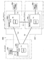
図1に示す計算機システム2000は、記憶システム1000を備えている。記憶システム1000は、正記憶サブシステム100aと、2つの副記憶サブシステム100b、100cを備えている。正記憶サブシステム100aは、2つの副記憶サブシステム100b、100cと、通信線CVを介してそれぞれ通信可能に接続されている。2つの副記憶サブシステム100b、100cは、互いに通信線CVを介して接続可能となっている。2つの副記憶サブシステム100b、100cは、後述する正常時においては、接続されていても接続されていなくても良いが、後述する障害時には、互いに通信可能に接続される必要がある。各記憶サブシステム100a〜100cは、それぞれ、異なるサイトに設置されている。以下、正記憶サブシステム100aが、設置されているサイトをメインサイト、2つの副記憶サブシステム100b、100cが設置されているサイトを、それぞれ、リモートサイト1、リモートサイト2と呼ぶ。
A
正記憶サブシステム100aは、メインサイトにおいて、正ホスト計算機200aと通信線CVを介して接続されている。2つの副記憶サブシステム100b、100cは、各リモートサイトにおいて、それぞれ、副ホスト計算機200b、200cと通信線CVを介して接続されている。通信線CVは、例えば、ファイバチャネルプロトコルを用いてデータ通信を行うネットワーク(FC−SAN)や、iSCSIプロトコルを用いてデータ通信を行うIPネットワーク(IP−SAN)が用いられ得る。
The
次に各記憶サブシステム100a〜100cのハードウエア構成について説明する。各記憶サブシステム100a〜100cのハードウエア構成は、基本的に同一である。以下の説明において、各記憶サブシステム100a〜100cを区別する必要がない場合には、符号の末尾のアルファベットを省略するものとする。
Next, the hardware configuration of each of the
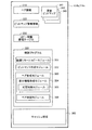
記憶サブシステム100は、図2に示すように、制御部110と、記憶部120とを備えている。制御部110は、記憶サブシステム100全体を制御する。例えば、制御部110は、主に、外部機器からデータを受信して、記憶部120に書き込んだり、記憶部120からデータを読み出して、外部機器に送信したりする。制御部110は、入出力アダプタ111〜113と、メモリ114と、中央演算装置(CPU)115、116と、ディスクアダプタ117〜119を備えている。これらの構成要素の数は、図2に示す数に限られるものではなく、例えば、メモリ114を複数個備えても良いし、CPUをさらに多数備えても良い。さらに、記憶サブシステム100の信頼性を向上させるために、メモリ114を二重化しても良い。
As illustrated in FIG. 2, the
入出力アダプタ111〜113は、外部機器とのデータやコマンドの入出力を実行するためのインターフェースである。メモリ114は、後述するように、制御部110の機能を実現するための制御プログラム等を格納している。CPU115、116は、上述した制御プログラムを実行することにより、制御部110の機能を実現するプロセッサである。ディスクアダプタ117〜119は、記憶部120とのデータの入出力を実行するためのインターフェースである。
The input /
記憶部120は、多数のディスク装置から構成されている。図2には、多数のディスク装置のうち、4つのディスク装置121〜124を図示している。これらのディスク装置は、データが実際に格納される物理的な記憶領域を提供する。これらのディスク装置は、制御部110の制御に従って、物理的な記憶領域に対するデータの読み出し/書き込みを実行する。制御部110は、これらの物理的な記憶領域を論理的な記憶領域である論理ボリュームに対応付けて管理している。図2に示す例では、ディスク装置121〜124の物理的な記憶領域を、複数の論理ボリュームV1〜V3に対応付けている。論理ボリュームと、物理的な記憶領域との対応付けは、例えば、いわゆるRAID(Redundant Array of Inexpensive Disks)と呼ばれる方式(RAID0、RAID5等、複数の種別がある)に従って、行われる。
The
記憶サブシステム100にアクセスする外部機器(例えば、上述した正ホスト計算機200a)には、論理ボリュームが記憶領域として提供される。各論理ボリュームは、それぞれ独立した記憶領域として扱われ、固有の論理ボリューム識別子によって、識別される。
A logical volume is provided as a storage area to an external device (for example, the
図1には、これらの論理ボリュームのうち、正記憶サブシステム100aの論理ボリュームVaと、副記憶サブシステム100bの論理ボリュームVbと、副記憶サブシステム100cの論理ボリュームVcが図示されている。論理ボリュームVa、Vb、Vcの識別子は、それぞれ「0000」、「FFA0」、「0001」とする。論理ボリュームVaは、正ホスト計算機200aに提供されている記憶領域である。論理ボリュームVbおよびVcは、論理ボリュームVaに格納されるデータの複製データを格納するための記憶領域である。正ボリュームと、正ボリュームに格納されたデータの複製データを格納するための副ボリュームとの組み合わせをコピーペアと呼ぶ。また、正ボリュームと副ボリュームとが異なる記憶サブシステム100に存在するコピーペアを、リモートコピーペアと呼ぶ。つまり、論理ボリュームVaと論理ボリュームVbは、論理ボリュームVaを正ボリュームとし、論理ボリュームVbを副ボリュームとするリモートコピーペアを構成している。同様に、論理ボリュームVaと論理ボリュームVcは、論理ボリュームVaを正ボリュームとし、論理ボリュームVcを副ボリュームとするリモートコピーペアを構成している。以下、前者を第1のリモートコピーペアとも呼び、後者を第2のリモートコピーペアとも呼ぶ。
FIG. 1 shows the logical volume Va of the
次に、図3〜図9を参照して、記憶サブシステム100a〜100cのメモリの内部構成について説明する。ここで、各記憶サブシステム100a〜100cが有する構成要素を区別する場合には、図2を参照して説明した対応する構成要素の符号の末尾に、アルファベットを付すこととする。例えば、正記憶サブシステム100aのメモリは、メモリ114aと表現し、副記憶サブシステム100bのメモリは、メモリ114bと表現する。
Next, the internal configuration of the memories of the
図3は、正記憶サブシステム100aのメモリ114aの内部構成を示す概念図である。図4は、副記憶サブシステム100b、100cのメモリ114b、114cの内部構成を示す概念図である。図5は、ペア情報の内容を示す概念図である。図6は、カウント情報の内容を示す概念図である。図7は、更新ビットマップの内容を示す概念図である。図8は、ビットマップ管理情報の内容を示す概念図である。図9は、コピー情報管理テーブルの内容を示す概念図である。
FIG. 3 is a conceptual diagram showing an internal configuration of the
正記憶サブシステム100aのメモリ114aには、ペア情報210と、カウント情報220と、制御プログラム230が格納されている。さらに、メモリ114aには、各種データ(例えば、外部機器から受信したデータ、記憶部120から読み出したデータ)を一時的に格納するキャッシュ領域240が確保されている。
Pair
ペア情報210は、上述したコピーペアを定義している情報である。ペア情報210は、コピーペアを構成する正ボリュームおよび副ボリュームを特定するための情報を含んでいる。正ボリュームおよび副ボリュームは、存在する記憶サブシステム100の識別子と、記憶サブシステム100内におけるボリューム識別子とによって特定される。例えば、正記憶サブシステム100aに格納されるペア情報210は、正ボリュームと副ボリュームのうち少なくとも一方が、正記憶サブシステム100aに存在するコピーペアについてのペア情報である。図5(a)に示す例では、ペア情報210の番号1の行は、上述した第1のリモートコピーペアについて定義している。ペア情報210の番号1の行には、正ボリュームとしての論理ボリュームVa(図1)を特定するため、正記憶サブシステム100aの識別子「#100」と、論理ボリュームVaの識別子「0000」が記録されている。また、ペア情報210の番号1には、副ボリュームとしての論理ボリュームVb(図1)を特定するため副記憶サブシステム100bの識別子「#110」と、論理ボリュームVbの識別子「FFA0」が記録されている。同様にして、ペア情報210の番号2の行は、上述した第2のリモートコピーペアについて定義している。
The
さらに、ペア情報210は、各コピーペアのコピータイプ情報を含んでいる。コピータイプ情報は、例えば、同期コピーか非同期コピーかの別を表す情報である。簡単に説明すると、同期コピーは、外部機器から正ボリュームに対するライト要求を受信すると、副ボリュームを有する記憶サブシステム100にコピー情報を送信し、記憶サブシステム100からコピー情報の受信完了を示す応答があった後に、ライト要求の処理完了を外部機器に通知する。これに対し、非同期コピーは、外部機器から正ボリュームに対するライト要求を受信すると、コピー情報を送信する前に、ライト要求の処理完了を外部機器に通知する。非同期コピーにおいて、副ボリュームを有する記憶サブシステム100へのコピー情報の送信は、バックグラウンドで行われる。
Further, the
カウント情報220は、図6に示すように、ライト番号およびライト区分番号のカウント値を記録している。ライト番号は、リモートコピーペアの正ボリュームごとに記録される。ここで、ライト番号は、あくまで、リモートコピーペアの正ボリュームごとに取得され、リモートコピーペアごとではない。図1に示すように、リモートコピーペアの正ボリュームが論理ボリュームVa1つであれば、1つのライト番号が記録される。すなわち、正ボリュームが共通する複数のリモートコピーペア(例えば、図1における第1のリモートコピーペアと第2のリモートコピーペア)では、共通のライト番号が用いられる。一方、ライト区分番号は、1つの値を記録している。ライト番号およびライト区分番号については、後述する。
As shown in FIG. 6, the
制御プログラム230は、正記憶サブシステム100aの制御部110aの機能を実現するための様々なモジュールを含んでいるが、図3には、実施例の説明に必要なモジュールについてのみ図示している。制御プログラム230は、リード/ライトモジュール231と、正側リモートコピーモジュール232と、ライト区分管理モジュール233とを含んでいる。リード/ライトモジュール231は、外部機器(例えば、正ホスト計算機200a)から送信されてくるライト要求およびリード要求を受信する。また、リード/ライトモジュール231は、ライト要求に対応するライトデータを、正記憶サブシステム100a内の論理ボリュームに書き込むライト処理を実行する。さらに、リード/ライトモジュール231は、リード要求に対応するデータを、正記憶サブシステム100a内の論理ボリュームから読み出し、外部機器に送信するリード処理を実行する。正側リモートコピーモジュール232は、正記憶サブシステム100a内にあるリモートコピーペアの正ボリュームに対するライト処理に対応するコピー情報を、リモートコピー先、すなわち、リモートコピーペアの副ボリュームを有する記憶サブシステム100(例えば、副記憶サブシステム100b)に送信する。コピー情報は、対応するライト処理におけるライトデータを副ボリュームにコピーするための情報である。ライト区分管理モジュール233は、ライト区分に関連する処理を実行する。ライト区分は、上述したライト処理に対応するコピー情報が属する時間的な区分である。ライト区分管理モジュール233は、サブモジュールとして、区分決定モジュール234と、区分情報送信モジュール235を含む。区分決定モジュール234は、ライト処理ごとに、ライト処理に対応するコピー情報が属するライト区分を決定する。ライト区分は、ライト処理ごとに定められるので、同一のライト処理に対応するコピー情報(例えば、複数の異なる副ボリュームに送信される各コピー情報)は、同一のライト区分に属する。各ライト区分は、ライト区分番号によって識別される。区分情報送信モジュール235は、区分情報を、リモートコピー先の記憶サブシステム100に通知する。区分情報は、上述したコピー情報が属するライト区分を、リモートコピー先の記憶サブシステム100において特定するための情報である。本実施例では、区分情報として、BMマーカと呼ばれるデータと、各コピー情報に含められるライト区分番号とが用いられるが、これについての詳細は後述する。
The
副記憶サブシステム100b、100cのメモリ114b、114cには、それぞれ、ペア情報310と、ビットマップ管理情報320と、コピー情報管理テーブル330と、更新ビットマップ341〜343と、制御プログラム350が格納されている。さらに、メモリ114b、114cには、上述したメモリ114aと同様に、各種データ(例えば、外部機器から受信したデータ、記憶部120から読み出したデータ)を一時的に格納するキャッシュ領域360が確保されている。なお、以下の説明において、副記憶サブシステム100bのメモリ114bに格納されている要素と、副記憶サブシステム100cのメモリ114cに格納されている要素を区別する必要がある場合には、符号の末尾に、アルファベット「b」「c」を付すことによって区別する。例えば、副記憶サブシステム100bの更新ビットマップは、符号「341b〜343b」を用いて表し、副記憶サブシステム100cの更新ビットマップは、符号「341c〜343c」を用いて表す。
The
ペア情報310は、上述したペア情報210と同様に、コピーペアを定義している情報である。例えば、副記憶サブシステム100bに格納されるペア情報310bは、正ボリュームと副ボリュームのうち少なくとも一方が、副記憶サブシステム100bに存在するコピーペアについてのペア情報である。図5(b)に示す例では、ペア情報310bの番号1の行は、副記憶サブシステム100bの論理ボリュームVbを副ボリュームとする上述した第1のリモートコピーペアについて定義している。同様に、副記憶サブシステム100cに格納されるペア情報310cは、正ボリュームと副ボリュームのうち少なくとも一方が、副記憶サブシステム100cに存在するコピーペアについてのペア情報である。図5(c)に示す例では、ペア情報310cの番号1の行は、副記憶サブシステム100cの論理ボリュームVcを副ボリュームとする上述した第2のリモートコピーペアについて定義している。
The
更新ビットマップ341〜342は、リモートコピーペアの副ボリュームにおいて、リモートコピーによるデータの変更履歴を記録するためのマップである。更新ビットマップ341〜342は、副ボリュームごとに用意される。具体的には、更新ビットマップ341〜342は、副ボリュームを複数のサブ記憶領域に分割して、サブ記憶領域ごとに、リモートコピーによるデータ変更の有無を記録している。本実施例では、各論理ボリュームは、トラックと呼ばれる論理的なサブ記憶領域を用いて管理されている。図7には、論理ボリュームVb、Vcと、論理ボリュームVb、Vc内部の複数のトラックTRとが概念的に示されている。論理ボリュームVb、Vc内に図示された複数のブロックの1つ1つが、1つのトラックTRを表している。なお、図7の左側において、ハッチングされたトラックTRは、リモートコピーによるデータの変更がされたトラックを表している。本実施例において、更新ビットマップ341〜342は、図7の右側に示すように、記録対象の副ボリュームが有するトラックTRごとに用意された1ビットのデータBDの集合である。1つのトラックTRと、1つのデータBDは、1対1に対応している。そして、各データBDの初期値を「0」とし(図示省略)、図7右側に示すように、データの変更がされたトラックに対応するデータBDを「1」と変更する。1つの更新ビットマップには、1つの対象ライト区分が定められている。1つの更新ビットマップには、定められた対象ライト区分に属するコピー情報に対応するコピー処理の履歴が記録される。これについての詳細は後述する。 The update bitmaps 341 to 342 are maps for recording the data change history by remote copy in the secondary volume of the remote copy pair. The update bitmaps 341 to 342 are prepared for each secondary volume. Specifically, the update bitmaps 341 to 342 divide the secondary volume into a plurality of sub storage areas, and record the presence / absence of data change by remote copy for each sub storage area. In this embodiment, each logical volume is managed using a logical sub storage area called a track. FIG. 7 conceptually shows the logical volumes Vb and Vc and a plurality of tracks TR inside the logical volumes Vb and Vc. Each of the plurality of blocks shown in the logical volumes Vb and Vc represents one track TR. On the left side of FIG. 7, the hatched track TR represents a track whose data has been changed by remote copy. In this embodiment, the update bitmaps 341 to 342 are a set of 1-bit data BD prepared for each track TR included in the secondary volume to be recorded, as shown on the right side of FIG. One track TR and one data BD have a one-to-one correspondence. Then, the initial value of each data BD is set to “0” (not shown), and the data BD corresponding to the track whose data has been changed is changed to “1” as shown on the right side of FIG. One target write section is defined in one update bitmap. In one update bitmap, a history of copy processing corresponding to copy information belonging to a predetermined target write section is recorded. Details of this will be described later.
ビットマップ管理情報320は、上述した更新ビットマップ341〜343の属性を表す情報である。ビットマップ管理情報320は、図8に示すように、ビットマップ番号と、対象ライト区分と、BMマーカ情報と、ステータスとを含む。ビットマップ番号は、3つの更新ビットマップ341〜343を識別するための識別子であり、それぞれ、1〜3が用いられている。対象ライト区分は、更新ビットマップの対象ライト区分のライト区分番号を示す。BMマーカ情報は、更新ビットマップの対象ライト区分に対応するBMマーカに関する情報である。更新ビットマップの対象ライト区分に対応するBMマーカが、副記憶サブシステム100b、100cにおいて受信されていない場合、BMマーカ情報として「未受信」が記録されている。一方、更新ビットマップの対象ライト区分に対応するBMマーカが、副記憶サブシステム100b、100cにおいて受信されると、BMマーカに含まれるライト番号が、BMマーカ情報として記録される。ステータスは、更新ビットマップが確定されているか、未確定であるかを示す情報である。これらの各情報の詳細については、後述する。
The
コピー情報管理テーブル330は、副記憶サブシステム100b、100cが、コピー情報の受信状況を管理するためのテーブルである。コピー情報は、ライト番号により管理されており、コピー情報管理テーブル330には、受信されたコピー情報のライト番号が記録されている。また、コピー情報のライト番号は、リモートコピーペアの副ボリュームごとに記録されている。
The copy information management table 330 is a table for the
制御プログラム350は、副記憶サブシステム100b、100cの制御部110b、100cの機能を実現するための様々なモジュールを含んでいるが、図4には、実施例の説明に必要なモジュールについてのみ図示している。制御プログラム350は、副側リモートコピーモジュール351と、ビットマップ作成モジュール352と、ペア形成モジュール353とを含んでいる。副側リモートコピーモジュール351は、正ボリュームを有する記憶サブシステム100(例えば、正記憶サブシステム100a)から送信されてくるコピー情報を用いて、副ボリュームにライトデータを書き込むコピー処理を実行する。ビットマップ作成モジュール352は、上述した更新ビットマップの作成、すなわち、コピー処理の履歴情報の作成を実行する。ペア形成モジュール353は、正ボリュームに障害が発生した場合に、その正ボリュームの2つの副ボリュームを用いて新たなリモートコピーペアを形成する。例えば、図1において、論理ボリュームVaに障害が発生した場合に、論理ボリュームVbを新たな正ボリュームとし、論理ボリュームVcを新たな副ボリュームとするリモートコピーペアを形成する。ペア形成モジュール353は、サブモジュールとして、差分情報作成モジュール354と、ペア同期モジュール356とを備える。差分情報作成モジュール354は、新たに形成すべきリモートコピーペアを構成する一方の論理ボリュームに記録されているデータと、他方の論理ボリュームに記録されているデータとの差分を示す差分情報を作成する。また、差分情報作成モジュール354は、差分情報の作成の可否を判断する可否判断モジュール355を備えている。ペア同期モジュール356は、差分情報を用いて、新たに形成すべきリモートコピーペアを構成する2つのボリューム間で、記録されているデータを一致させる。
The
・リモートコピー関連処理:
図10〜図18を参照して、本実施例におけるリモートコピー関連処理について説明する。リモートコピー関連処理は、正記憶サブシステム100aにおいて実行されるライト要求処理と、非同期書き込み処理と、非同期送信処理と、ライト区分管理処理を含む。リモートコピー関連処理は、副記憶サブシステム100b、100cにおいて実行されるコピー情報処理と、BMマーカ処理とを含む。図10は、本実施例におけるリモートコピー関連処理の概要を示す説明図である。図11は、コピー情報の一例を概念的に示す説明図である。図12は、BMマーカの一例を概念的に示す説明図である。図13は、ライト要求処理の処理ルーチンを示すフローチャートである。図14は、ライト区分管理処理の処理ルーチンを示すフローチャートである。図15は、非同期書き込み処理の処理ルーチンを示すフローチャートである。図16は、非同期送信処理の処理ルーチンを示すフローチャートである。図17は、コピー情報処理の処理ルーチンを示すフローチャートである。図18は、BMマーカ処理の処理ルーチンを示すフローチャートである。
-Remote copy related processing:
With reference to FIGS. 10 to 18, the remote copy related processing in this embodiment will be described. The remote copy related process includes a write request process, an asynchronous write process, an asynchronous transmission process, and a write partition management process executed in the
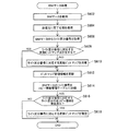
正ホスト計算機200aは、正記憶サブシステム100aから提供されている論理ボリュームVaにデータを書き込む場合、ライト要求10を正記憶サブシステム100aに送信する。ライト要求10は、ライトデータと共に、正記憶サブシステム100aがライト処理を実行するために必要な属性情報を含む。属性情報には、例えば、ライトデータを書き込む位置を特定するためのアドレスやライトデータの大きさを表す情報が含まれる。リモートコピー関連処理は、図10に示すように、正ホスト計算機200aからライト要求10を受信することによって、開始される。まず、受信されたライト要求10を処理するライト要求処理を説明する。
When the
ライト要求処理は、正記憶サブシステム100aの制御部110aが上述した制御プログラム230の正側リモートコピーモジュール232を用いて実行する処理である。ライト要求処理は、正記憶サブシステム100aがライト要求10を受信すると、開始される。ライト要求処理が開始されると、制御部110aは、ライト要求10を取得する(ステップS102)。制御部110aは、ライト要求10がリモートコピーの対象か否かを判断する(ステップS104)。具体的には、制御部110aは、ライト要求10に含まれる属性情報からライトデータを書き込むべき論理ボリュームを特定する。制御部110aは、上述したペア情報210(図5(a))を参照し、書き込むべき論理ボリュームが、リモートコピーペアの正ボリュームであるか否かを調べる。制御部110aは、書き込むべき論理ボリュームがリモートコピーペアの正ボリュームである場合には、当該ライト要求10がリモートコピーの対象であると判断する(ステップS104:YES)。一方、制御部110aは、書き込むべき論理ボリュームがリモートコピーペアの正ボリュームでない場合には、当該ライト要求10がリモートコピーの対象でないと判断する(ステップS104:NO)。図10に、示すように、ライト要求10が、論理ボリュームVaに対するものである場合には、論理ボリュームVaは上述した第1および第2のリモートコピーペアの正ボリュームであるから、当該ライト要求10は、リモートコピーの対象であると判断される。
The write request process is a process executed by the control unit 110a of the
ライト要求10がリモートコピーの対象でないと判断すると(ステップS104:NO)、制御部110aは、正ホスト計算機200aに対してライト要求の処理完了を通知して(ステップS124)、本処理を終了する。一方、ライト要求10がリモートコピーの対象であると判断すると(ステップS104:YES)、制御部110aは、上述したカウント情報220に記録されているライト番号のカウント値を取得する(ステップS106)。取得されるライト番号のカウント値は、ライト要求が書き込み対象とする正ボリュームについての値である。次に、制御部110aは、カウント情報220において、ライト要求が書き込み対象とする正ボリュームについて、ライト番号のカウント値をインクリメントしておく(ステップS108)。さらに、制御部110aは、カウント情報220に記録されているライト区分番号のカウント値を取得する(ステップS110)。本ステップにより取得されたライト区分番号を有するライト区分が、処理中のライト要求に対応するライト処理および当該ライト処理に対応するコピー情報が属するライト区分とされる。後述するように、ライト区分番号は、時間の経過と共に更新されるので、ライト要求に対応するライト処理および当該ライト処理に対応するコピー情報が属するライト区分は、本処理において、ライト区分番号が取得される時を基準に決定されることになる。
If it is determined that the
ライト区分番号のカウント値が取得されると、制御部110aは、コピー情報20を生成する(ステップS122)。図11に示すように、生成されるコピー情報20は、ステップS102において取得されたライト要求10に含まれる属性情報21とライトデータ24に加えて、ステップS106、S110においてそれぞれ取得されたライト番号22、ライト区分番号23を含む。
When the count value of the write section number is acquired, the control unit 110a generates copy information 20 (step S122). As shown in FIG. 11, the generated
コピー情報20が生成されると、制御部110aは、非同期送信先はあるか否かを判断する(ステップS114)。具体的には、制御部110aは、上述したペア情報210(図5(a))を参照して、ライト要求10が書き込みを要求する論理ボリュームを正ボリュームとするリモートコピーペアのコピータイプ情報を取得する。そして、制御部110aは、取得されたコピータイプ情報に「非同期コピー」がある場合には、非同期送信先はあると判断する(ステップS114:YES)。一方、制御部110aは、取得されたコピータイプ情報に「非同期コピー」がない場合には、非同期送信先はないと判断する(ステップS114:NO)。
When the
非同期送信先がないと判断されると(ステップS114:NO)、制御部110aは、ステップS118に移行する。一方、非同期送信先があると判断されると(ステップS114:YES)、制御部110aは、生成されたコピー情報20を非同期送信の対象として登録する(ステップS116)。具体的には、メモリ114aのキャッシュ領域240に、非同期送信の対象となるデータを格納するための領域が用意されており、当該領域にコピー情報20が書き込まれることにより、非同期送信の対象として登録される。
If it is determined that there is no asynchronous transmission destination (step S114: NO), the controller 110a proceeds to step S118. On the other hand, if it is determined that there is an asynchronous transmission destination (step S114: YES), the control unit 110a registers the generated
続いて、制御部110aは、同期送信先はあるか否かを判断する(ステップS118)。具体的には、制御部110aは、ステップS114において取得されたコピータイプ情報に「同期コピー」がある場合には、同期送信先はあると判断する(ステップS118:YES)。一方、制御部110aは、取得されたコピータイプ情報に「同期コピー」がない場合には、同期送信先はないと判断する(ステップS118:NO)。 Subsequently, the control unit 110a determines whether there is a synchronous transmission destination (step S118). Specifically, when the copy type information acquired in step S114 includes “synchronous copy”, control unit 110a determines that there is a synchronous transmission destination (step S118: YES). On the other hand, when there is no “synchronous copy” in the acquired copy type information, the control unit 110a determines that there is no synchronous transmission destination (step S118: NO).
同期送信先がないと判断されると(ステップS118:NO)、制御部110aは、正ホスト計算機200aに対してライト要求の処理完了を通知して(ステップS124)、本処理を終了する。一方、同期送信先があると判断されると(ステップS118:YES)、制御部110aは、生成されたコピー情報20を、同期送信先、すなわち、リモートコピーの副ボリュームを有する記憶サブシステム100に送信する(ステップS120)。そして、制御部110aは、コピー情報の受信完了を示す完了応答を、同期送信から受信すると(ステップS122)、正ホスト計算機200aに対してライト要求の処理完了を通知して(ステップS124)、本処理を終了する。
If it is determined that there is no synchronous transmission destination (step S118: NO), the control unit 110a notifies the
論理ボリュームVa(図1)に対するライト要求10が本処理によって処理された場合を考える。論理ボリュームVaを正ボリュームとする第1のリモートコピーペアはコピータイプが同期コピーである(図5(a))。したがって、ステップS120において、コピー情報20は、第1のコピーペアの副ボリュームである論理ボリュームVbを有する副記憶サブシステム100bに送信される。さらに、論理ボリュームVaを正ボリュームとする第2のリモートコピーペアはコピータイプが非同期コピーである(図5(a))。したがって、ステップS116において、コピー情報20は、非同期送信対象に登録される。
Consider a case where the
次に、上述したライト要求処理と並行して行われているライト区分管理処理について説明する。ライト区分管理処理は、正記憶サブシステム100aの制御部110aが上述した制御プログラム230のライト区分管理モジュール233を用いて実行する処理である。ライト区分管理処理は、正記憶サブシステム100aがライト要求を受け付けている時には、常に実行されている。ライト区分管理処理が開始されると、制御部110aは、ライト区分番号を初期値に設定する(ステップS202)。ライト区分番号の初期値は、例えば、「#0」とする。ここで、本明細書において、他の番号、例えば、ライト番号とはっきり区別するため、ライト区分番号は、数字の前に「#」を付す。初期値とされたライト区間番号は、上述したカウント情報220に記録される。
Next, the write classification management process performed in parallel with the write request process described above will be described. The write section management process is a process executed by the control unit 110a of the
次に、制御部110aは、ライト区分の時間的な長さT(以下、区分期間Tという。)を設定する(ステップS204)。区分期間Tは、予め定められた所定値、例えば、1分とされる。制御部110aは、続いて、ライト区分の更新時間か否かを判断する(ステップS206)。ライト区分は、上述した区分期間Tごとに更新される。本ステップでは、最近のライト区分の更新から区分期間Tが経過したか否かが判断されることになる。制御部110aは、ライト区分の更新時間でないと判断すると(ステップS206:NO)、ライト区分の更新時間まで待機する。制御部110aは、ライト区分の更新時間であると判断すると(ステップS206:YES)、カウント情報220からライト番号のカウント値を取得する(ステップS208)。取得されるライト番号のカウント値は、正記憶サブシステム100aに設定されているリモートコピーペアの正ボリュームごとに、1つずつ取得される。続いて、制御部110aは、カウント情報220に記録されているライト番号のカウント値をインクリメントしておく(ステップS210)。
Next, the control unit 110a sets the time length T of the write section (hereinafter referred to as the section period T) (step S204). The division period T is set to a predetermined value, for example, 1 minute. Subsequently, the control unit 110a determines whether it is the update time of the write section (step S206). The write section is updated every section period T described above. In this step, it is determined whether or not the segment period T has elapsed since the latest write segment update. If it is determined that it is not the update time of the light section (step S206: NO), the control unit 110a waits until the update time of the write section. When determining that it is the update time of the write section (step S206: YES), the control unit 110a acquires the count value of the write number from the count information 220 (step S208). The count value of the acquired write number is acquired for each primary volume of the remote copy pair set in the
制御部110aは、カウント情報220に記録されているライト区分番号のカウント値を取得する(ステップS212)。制御部110aは、次に、カウント情報220に記録されているライト区分番号のカウント値をインクリメントしておく(ステップS214)。次に、制御部110aは、BMマーカ30を生成する(ステップS216)。図12に示すように、生成されるBMマーカ30は、BMマーカであることを示す属性情報31と共に、ステップS208、S212においてそれぞれ取得されたライト番号32、ライト区分番号33を含む。
The control unit 110a acquires the count value of the write section number recorded in the count information 220 (Step S212). Next, the control unit 110a increments the count value of the write section number recorded in the count information 220 (step S214). Next, the control unit 110a generates the BM marker 30 (step S216). As shown in FIG. 12, the generated
BMマーカが生成されると、制御部110aは、非同期送信先はあるか否かを判断する(ステップS218)。具体的には、110aは、上述したペア情報210(図5(a))を参照して、正記憶サブシステム100aに正ボリュームが存在するリモートコピーペアの中に、コピータイプが非同期コピーであるものがあるか否かを判断する。そして、制御部110aは、コピータイプが非同期コピーであるものがある場合には、非同期送信先はあると判断する(ステップS218:YES)。一方、制御部110aは、コピータイプが非同期コピーであるものがない場合には、非同期送信先はないと判断する(ステップS218:NO)。
When the BM marker is generated, the control unit 110a determines whether there is an asynchronous transmission destination (step S218). Specifically, with reference to the above-described pair information 210 (FIG. 5A), the copy type 110a is an asynchronous copy in a remote copy pair in which a primary volume exists in the
非同期送信先がないと判断されると(ステップS218:NO)、制御部110aは、ステップS222に移行する。一方、非同期送信先があると判断されると(ステップS218:YES)、制御部110aは、生成されたBMマーカを非同期送信の対象として登録する(ステップS220)。 If it is determined that there is no asynchronous transmission destination (step S218: NO), the control unit 110a proceeds to step S222. On the other hand, if it is determined that there is an asynchronous transmission destination (step S218: YES), the control unit 110a registers the generated BM marker as an asynchronous transmission target (step S220).
続いて、制御部110aは、同期送信先はあるか否かを判断する(ステップS222)。具体的には、制御部110aは、上述したペア情報210(図5(a))を参照して、正記憶サブシステム100aに正ボリュームが存在するリモートコピーペアの中に、コピータイプが同期コピーであるものがあるか否かを判断する。そして、制御部110aは、コピータイプが同期コピーであるものがある場合には、同期送信先はあると判断する(ステップS222:YES)。一方、制御部110aは、コピータイプが同期コピーであるものがない場合には、同期送信先はないと判断する(ステップS222:NO)。
Subsequently, the control unit 110a determines whether there is a synchronous transmission destination (step S222). Specifically, the control unit 110a refers to the above-described pair information 210 (FIG. 5A), and the copy type is the synchronous copy in the remote copy pair in which the primary volume exists in the
同期送信先がないと判断されると(ステップS222:NO)、制御部110aは、ステップS206に戻り、次にライト区分更新時間まで待機する。一方、同期送信先があると判断されると(ステップS222:YES)、制御部110aは、生成されたBMマーカ30を、同期送信先、すなわち、リモートコピーの副ボリュームを有する記憶サブシステム100に送信する(ステップS224)。BMマーカは、本ステップにおいて、正記憶サブシステム100aに正ボリュームが存在するリモートコピーペアの副ボリュームを有する全ての記憶サブシステム100に送信される。そして、制御部110aは、BMマーカ30の受信完了を示す完了応答を、同期送信先から受信すると(ステップS226)、制御部110aは、ステップS206に戻り、次にライト区分更新時間まで待機する。
If it is determined that there is no synchronous transmission destination (step S222: NO), the control unit 110a returns to step S206 and then waits until the write section update time. On the other hand, when it is determined that there is a synchronous transmission destination (step S222: YES), the control unit 110a transfers the generated
本処理によって、一のライト区分に属するコピー情報の送信と、次のライト区分に属する最初コピー情報の送信との間のタイミングで、BMマーカ30が送信される。以上の説明から解るように、本実施例におけるBMマーカ30は、特許請求の範囲における境界情報に相当する。
With this process, the
続いて、上述したライト要求処理と並行して行われている非同期書き込み処理について説明する。非同期書き込み処理は、正記憶サブシステム100aの制御部110aが上述した制御プログラム230のリード/ライトモジュール231を用いて実行する処理である。
Next, an asynchronous write process that is performed in parallel with the write request process described above will be described. The asynchronous write process is a process executed by the control unit 110a of the
非同期書き込み処理は、正記憶サブシステム100aがライト要求を受け付けている時には、常に実行されている。非同期書き込み処理が実行されている間、制御部110aは、常にメモリ114aに、まだ書き込みがされていないライト要求10が有るか否かを監視している(ステップS302)。書き込みがされていないライト要求10が有ると判断すると(ステップS302:YES)、制御部110aは、ライト要求10に従って、ライトデータを、論理ボリュームに書き込むライト処理を実行する(ステップS304)。ここで、メモリ114aに複数の未書き込みのライト要求10がある場合には、ライト要求10が受信された順番が解るようにメモリ114aに格納されている。制御部110aは、ライト要求が受信された順番に、論理ボリュームに書き込まれる。
Asynchronous write processing is always executed when the
次に、上述したライト要求処理と並行して行われている非同期送信処理について説明する。非同期送信処理は、正記憶サブシステム100aの制御部110aが上述した制御プログラム230の正側リモートコピーモジュール232を用いて実行する処理である。
Next, an asynchronous transmission process performed in parallel with the above-described write request process will be described. The asynchronous transmission process is a process executed by the control unit 110a of the
非同期送信処理は、正記憶サブシステム100aがライト要求を受け付けている時には、常に実行されている。非同期送信処理が実行されている間、制御部110aは、常に、非同期送信対象に登録されているデータがあるか否かを監視している(ステップS402)。非同期送信対象に登録されているデータには、ライト要求処理において登録されたコピー情報20(図13:ステップ116)、および、ライト区分管理処理において登録されたBMマーカ30(図14:ステップS216)が含まれる。制御部110aは、非同期送信対象に登録されているデータがあると判断すると(ステップS402:YES)、当該データを非同期送信先に送信する(ステップS404)。非同期送信先は、当該データがコピー情報20である場合には、当該コピー情報20に含まれる属性情報21とペア情報210とを参照することによって特定される。一方、当該データがBMマーカ30である場合には、ペア情報210を参照して特定される。ここで、非同期送信先は、1つに限られず、複数である場合もある。また、非同期送信対象のデータが複数登録されている場合には、非同期送信対象のデータは、登録された順番に送信される。そして、制御部110aは、送信したデータの受信完了を示す完了応答を、同期送信先から受信すると(ステップS406)、送信したデータを、非同期送信対象から削除する(ステップS408)。その後、制御部110aは、ステップS402にリターンする。
Asynchronous transmission processing is always executed when the
続いて、コピー情報処理について説明する。コピー情報処理は、副記憶サブシステム100b、100cの制御部110b、110cが、上述した制御プログラム350の副側リモートコピーモジュール351とビットマップ作成モジュール352を用いて実行する処理である。コピー情報処理は、副記憶サブシステム100b、100cにおいて、コピー情報20が受信されると、開始される。いずれの副記憶サブシステムにおいても同一の処理であるので、以下では、副記憶サブシステム100bの制御部110bによるコピー情報処理を説明する。コピー情報処理を開始されると、制御部110bは、コピー情報20を取得する(ステップS502)。制御部110bは、コピー情報20の送信元(本実施例では、正記憶サブシステム100a)に対して、コピー情報20の受信完了を示す完了応答を送信する(ステップS504)。制御部110bは、取得されたコピー情報20に従って、ライトデータを副ボリュームに書き込むコピー処理を実行する(ステップS506)。
Next, copy information processing will be described. Copy information processing is processing executed by the control units 110b and 110c of the
制御部110bは、続いて、コピー情報20に含まれるライト区分番号を取得する(ステップS508)。制御部110bは、取得されたライト区分番号のライト区分を記録対象とする更新ビットマップは存在するか否かを判断する(ステップS510)。具体的には、制御部110bは、上述したビットマップ管理情報320を参照して、更新ビットマップ341〜343の対象ライト区分番号を調べる。取得されたライト区分番号のライト区分を記録対象とする更新ビットマップがある場合には(ステップS510:YES)、制御部110bは、ステップS516に移行する。取得されたライト区分番号のライト区分を記録対象とする更新ビットマップがない場合には(ステップS510:NO)、取得されたライト区分番号のライト区分を記録対象とする更新ビットマップを新たに用意する(ステップS512)。例えば、未使用の更新ビットマップが存在する場合には、制御部110bは、その更新ビットマップの対象ライト区分を、取得されたライト区分番号のライト区分とする。また、未使用の更新ビットマップが存在しない場合には、制御部110bは、最も古いライト区分、すなわち、最もライト区分番号が小さいライト区分を対象ライト区分とする更新ビットマップをクリアする。そして、制御部110bは、クリアされた更新ビットマップの対象ライト区分を、取得されたライト区分番号のライト区分とする。制御部110bは、このような、更新ビットマップの属性の変更に応じて、ビットマップ管理情報320を更新する(ステップS514)。
Subsequently, the control unit 110b acquires the write section number included in the copy information 20 (step S508). The control unit 110b determines whether or not there is an update bitmap that records the write section of the acquired write section number as a recording target (step S510). Specifically, the control unit 110b refers to the
制御部110bは、取得されたライト区分番号のライト区分を記録対象とする更新ビットマップに、ステップS506において書き込んだライトデータの書き込み位置を記録する(ステップS516)。具体的には、制御部110bは、当該更新ビットマップにおいて、ライトデータが書き込まれたトラックTRに対応する1ビットのデータBDを「1」にする。そして、制御部110bは、処理中のコピー情報20のライト番号22の値を、コピー情報管理テーブル330に、副ボリュームごとに記録する(ステップS518)。
The control unit 110b records the write position of the write data written in step S506 in the update bitmap that records the write section of the acquired write section number as a recording target (step S516). Specifically, the control unit 110b sets 1-bit data BD corresponding to the track TR in which the write data is written to “1” in the update bitmap. Then, the control unit 110b records the value of the
ついで、制御部110bは、更新ビットマップを確定するための処理(ステップS520〜S524)に移る。まず、制御部110bは、更新ビットマップ341〜343の中に、未確定、かつ、BMマーカ30を受信済みの更新ビットマップがあるか否かを判断する(ステップS520)。具体的には、制御部110bは、ビットマップ管理情報320を参照して、ビットマップ管理情報320において、BMマーカ情報が未受信でなく、かつ、ステータスが未確定であると記録されている更新ビットマップがあるか否かを調べる。未確定、かつ、BMマーカ30を受信済みの更新ビットマップがないと判断すると(ステップS520:NO)、本処理を終了する。一方、BMマーカ30を受信済みの更新ビットマップがあると判断すると(ステップS520:YES)、当該更新ビットマップの対象ライト区分に属するコピー情報20を全て受信しているか否かを判断する(ステップS522)。具体的には、制御部110bは、ビットマップ管理情報320における当該更新ビットマップのBMマーカ情報として記録されているライト番号(図8)を取得する。そして、制御部110bは、コピー情報管理テーブル330を参照して、BMマーカ情報として記録されているライト番号未満のライト番号を有するコピー情報が全て受信されているか否かを判断する。
Next, the control unit 110b moves to a process (steps S520 to S524) for determining an update bitmap. First, the control unit 110b determines whether there is an update bitmap that has not been confirmed and that has received the
制御部110bは、当該更新ビットマップの対象ライト区分に属するコピー情報20を全て受信していないと判断すると(ステップS522:NO)、本処理を終了する。一方、制御部110bは、当該更新ビットマップの対象ライト区分に属するコピー情報20を全て受信していると判断すると(ステップS522:YES)、当該更新ビットマップを確定して(ステップS524)、本処理を終了する。更新ビットマップの確定は、ビットマップ管理情報320における当該更新ビットマップのステータスを「未確定」から「確定」に変更することによって行われる。
If the control unit 110b determines that all the
続いて、BMマーカ処理について説明する。BMマーカ処理は、副記憶サブシステム100b、100cの制御部110b、110cが、上述した制御プログラム350の副側リモートコピーモジュール351とビットマップ作成モジュール352を用いて実行する処理である。BMマーカ処理は、副記憶サブシステム100b、100cにおいて、BMマーカ30が受信されると、開始される。いずれの副記憶サブシステムにおいても同一の処理であるので、以下では、副記憶サブシステム100bの制御部110bによるBMマーカ処理を説明する。BMマーカ処理を開始されると、制御部110bは、BMマーカ30を取得する(ステップS602)。制御部110bは、BMマーカ30の送信元(本実施例では、正記憶サブシステム100a)に対して、BMマーカ30の受信完了を示す完了応答を送信する(ステップS604)。
Subsequently, the BM marker process will be described. The BM marker process is a process executed by the control units 110b and 110c of the
制御部110bは、続いて、BMマーカ30に含まれるライト区分番号を取得する(ステップS606)。制御部110bは、上述したコピー情報処理におけるステップS510と同様に、取得されたライト区分番号のライト区分を記録対象とする更新ビットマップは存在するか否かを判断する(ステップS608)。取得されたライト区分番号のライト区分を記録対象とする更新ビットマップがある場合には(ステップS608:YES)、制御部110bは、ステップS612に移行する。取得されたライト区分番号のライト区分を記録対象とする更新ビットマップがない場合には(ステップS608:NO)、上述したコピー情報処理におけるステップS512と同様に、取得されたライト区分番号のライト区分を記録対象とする更新ビットマップを新たに用意する(ステップS610)。 Subsequently, the control unit 110b acquires the light section number included in the BM marker 30 (step S606). The control unit 110b determines whether or not there is an update bitmap that records the write section of the acquired write section number as in step S510 in the copy information processing described above (step S608). If there is an update bitmap that records the acquired write section with the write section number (step S608: YES), the controller 110b proceeds to step S612. If there is no update bitmap for recording the write section of the acquired write section number (step S608: NO), the write section of the acquired write section number is the same as in step S512 in the copy information processing described above. Is newly prepared as a recording bitmap (step S610).
制御部110bは、取得されたライト区分番号のライト区分を記録対象とする更新ビットマップについて、ビットマップ管理情報320を更新する(ステップS610)。具体的には、制御部110bは、ステップS506において書き込んだライトデータの書き込み位置を記録する。具体的には、取得されたライト区分番号のライト区分を記録対象とする更新ビットマップのBMマーカ情報を、「未受信」から「BMマーカ30に含まれるライト番号」に変更する。制御部110bは、BMマーカ30に含まれるライト番号をコピー情報管理テーブル330にも記録しておく(ステップS614)。
The control unit 110b updates the
ついで、制御部110bは、更新ビットマップを確定するための処理(ステップS616〜S618)に移る。まず、制御部110bは、BMマーカ30に含まれるライト区分番号のライト区分に属するコピー情報20を全て受信しているか否かを判断する(ステップS616)。具体的には、制御部110bは、コピー情報管理テーブル330を参照して、BMマーカに含まれるライト番号未満のライト番号を有するコピー情報が全て受信されているか否かを判断する。制御部110bは、コピー情報20を全て受信していないと判断すると(ステップS616:NO)、本処理を終了する。一方、制御部110bは、コピー情報20を全て受信していると判断すると(ステップS616:YES)、BMマーカ30に含まれるライト区分番号のライト区分を対象ライト区分とする更新ビットマップを確定して(ステップS618)、本処理を終了する。
Next, the control unit 110b moves to processing for determining an update bitmap (steps S616 to S618). First, the control unit 110b determines whether or not all the
以上説明したリモートコピー関連処理を、図10を参照して、さらに説明する。図10には、各論理ボリュームVa、Vb、Vcと、論理ボリュームVa、Vb、Vc内部の複数のトラックTRとが概念的に示されている。図10には、論理ボリュームVaに対する9つのライト要求10が、正ホスト計算機200aから正記憶サブシステム100aへ順次送信される様子を示している。上述した非同期書き込み処理(図15)によって、各ライト要求10に対応するライト処理が、論理ボリュームVaに対して実行される。また、上述したライト要求処理(図13)と、非同期送信処理(図16)によって、各ライト要求10に対応するコピー情報20が、論理ボリュームVaとリモートコピーペアを構成する副ボリュームである論理ボリュームVb、Vcを有する副記憶サブシステム100b、100cに、それぞれ送信される。
The remote copy related processing described above will be further described with reference to FIG. FIG. 10 conceptually shows each logical volume Va, Vb, Vc and a plurality of tracks TR inside the logical volumes Va, Vb, Vc. FIG. 10 shows a state in which nine write
図10において、正記憶サブシステム100aから副記憶サブシステム100bへコピー情報20が送信される様子と、正記憶サブシステム100aから副記憶サブシステム100cへとコピー情報20が送信される様子が概念的に示されている。図10において、各コピー情報20に付されている番号は、コピー情報20に含まれるライト番号(図11)である。図10において、論理ボリュームVaのトラックTRに記された番号は、そのトラックTRが、ライト要求10に対応するライト処理が実行されたトラックTRであることを概念的に示している。ここで、理解の容易のため、論理ボリュームVaのトラックTRに記された番号は、ライト処理に対応するコピー情報20に含まれるライト番号とされている。
In FIG. 10, the state in which the
さらに、図10には、上述したライト区分管理処理(図14)と、非同期送信処理(図16)によって、送信されたBMマーカ30が、コピー情報20同様に、正記憶サブシステム100aから副記憶サブシステム100cへと送信される様子が示されている。先のBMマーカ30のライト番号から、後のBMマーカ30のライト番号のライト番号までに含まれるライト番号を有するコピー情報20は、後のBMマーカ30に含められたライト区分番号のライト区分に属する。例えば、図10では、ライト番号5未満、すなわち、ライト番号1〜4までのコピー情報20は、ライト区分#1に属する。そして、ライト番号6から次のBMマーカ30のライト番号9までのライト番号6〜8のコピー情報20は、ライト区分#2に属する。ここで、ライト区分#nは、ライト区分番号が#nであるライト区分を表すものとする。
Further, in FIG. 10, the
ここで、図10に示すように、同期送信により副記憶サブシステム100bに送信されるコピー情報20と、非同期送信により副記憶サブシステム100cに送信されるコピー情報20とは、対応する正ボリュームへのライト処理が同一であれば、同一のライト区分に属する。上述したライト要求処理からわかるように、正ボリュームである論理ボリュームVaへのライト処理ごとに、対応するコピー情報が属するライト区分が定められているからである。
Here, as shown in FIG. 10, the
さらに、上述したコピー情報処理(図17)により、副記憶サブシステム100bおよび副記憶サブシステム100cにおいて、コピー情報20を用いたコピー処理が実行される。また、上述したコピー情報処理(図17)、および、BMマーカ処理(図18)により、副記憶サブシステム100bにおいて、更新ビットマップ341b〜343bが作成され、副記憶サブシステム100cにおいて、更新ビットマップ341c〜343cが作成される。図10には、副記憶サブシステム100bにおいて、ライト番号1〜11までのコピー情報20を用いたコピー処理が実行された時点における論理ボリュームVbと、その時点における更新ビットマップ341b〜343bが図示されている。また、副記憶サブシステム100cにおいて、ライト番号1〜7までのコピー情報20を用いたコピー処理が実行された時点における論理ボリュームVcと、その時点における更新ビットマップ341c〜343cが図示されている。
Furthermore, the copy processing using the
図10において、論理ボリュームVbおよび論理ボリュームVbのトラックTRの一部には、ライト番号が記されている。ライト番号が記されたトラックTRは、そのライト番号のコピー情報20を用いたコピー処理により、ライトデータが書き込まれたトラックTRを示している。副記憶サブシステム100bにおいて、更新ビットマップ341bは、ライト区分#1が対象ライト区分である。更新ビットマップ341bは、ライト区分#1に属するコピー情報20に対応するコピー処理の履歴が全て記録されて、確定されている。同様にして、ライト区分#2を対象ライト区分とする更新ビットマップ342bも、記録すべきコピー処理の履歴が全て記録されて確定されている。また、ライト区分#3を対象ライト区分とする更新ビットマップ343bは、未確定である。この時点からさらに処理が進行して、ライト区分#4に属するコピー情報20あるいはBMマーカ30が受信されると、更新ビットマップ341bはクリアされ、更新ビットマップ341bのライト区分は、ライト区分#4とされることになる。
In FIG. 10, a write number is written in a part of the track TR of the logical volume Vb and the logical volume Vb. The track TR in which the write number is written indicates the track TR in which the write data is written by the copy process using the
一方、副記憶サブシステム100cにおいては、ライト番号1〜7までのコピー情報20を用いたコピー処理が実行された時点が示されている。従って、ライト区分#1が対象ライト区分である更新ビットマップ341cは確定している。そして、ライト区分#2が対象ライト区分である更新ビットマップ342cは、まだ、ライト区分#2に属するライト番号8のコピー情報20が受信されていないため、未確定である。
On the other hand, in the
以上説明したリモートコピー関連処理が実行されることにより、図1に示す記憶システム1000において、リモートコピーが実現される。
By executing the remote copy-related processing described above, remote copy is realized in the
・正ボリュームに障害が発生した際の処理:
図19〜図21を参照して、正ボリュームに障害が発生した際の処理について説明する。障害が発生した際の処理は、同一のボリュームを正ボリュームとするリモートコピーペアが2以上ある場合に、2つのリモートコピーペアの副ボリュームで新たなリモートコピーペアを形成するペア形成処理である。ペア形成処理により、データの冗長性を確保するシステム構成に、再び移行することができる。
-Processing when a failure occurs in the primary volume:
Processing when a failure occurs in the primary volume will be described with reference to FIGS. The processing when a failure occurs is a pair formation processing for forming a new remote copy pair with the secondary volumes of two remote copy pairs when there are two or more remote copy pairs having the same volume as the primary volume. By the pair formation process, it is possible to shift again to a system configuration that ensures data redundancy.
図19は、ペア形成処理の処理ルーチンを示すフローチャートである。図20は、差分情報の作成可否について説明するための表である。図21は、ペア形成処理の概要を示す説明図である。 FIG. 19 is a flowchart showing the processing routine of the pair formation processing. FIG. 20 is a table for explaining whether or not difference information can be created. FIG. 21 is an explanatory diagram showing an overview of the pair formation process.
図1に示す記憶システム1000において、第1および第2のリモートコピーペアの正ボリュームである論理ボリュームVaに障害が発生した場合を例に、ペア形成処理を説明する。前提として、ペア形成処理を実行するためには、副記憶サブシステム100bと副記憶サブシステム100cが、通信線CVによって、通信可能に接続されている必要がある。ペア形成処理は、リモートコピーペアの副ボリュームを有する記憶サブシステム100において実行される。図1に示す例では、副記憶サブシステム100bまたは副記憶サブシステム100cのいずれかにおいて実行される。いずれにおいても同一の処理が実行されるので、副記憶サブシステム100bにおいて実行されるものとして説明する。
In the
副記憶サブシステム100bにおいて、ペア形成処理は、制御部110bが、上述した制御プログラム350のペア形成モジュール353を用いて実行する処理である。ペア形成処理は、副ホスト計算機200bや、図示しない管理計算機を介して、ユーザから開始指示があった時に、開始される。ペア形成処理が開始されると、制御部110bは、新たに形成されるべきリモートコピーペアを構成する新正ボリュームおよび新副ボリュームを特定する(ステップS702)。ここで、区別を明確にするため、障害発生前に形成されていたリモートコピーペア、正ボリューム、副ボリュームは、「旧」を用語の前に付す。また、本処理により新たに形成されるリモートコピーペア、正ボリューム、副ボリュームは、「新」を用語の前に付す。新正ボリュームおよび新副ボリュームは、ユーザからの指示に従って特定される。以下、本ステップにおいて、副記憶サブシステム100bの論理ボリュームVbが新正ボリュームとして、副記憶サブシステム100cの論理ボリュームVcが新副ボリュームとして特定されたとして、説明する。
In the
次に、制御部110bは、新正ボリュームと新副ボリュームの双方のペア情報を取得する(ステップS704)。具体的には、制御部110bは、メモリ114bに格納されているペア情報310bを取得する。さらに、制御部110bは、通信線CVを介して、副記憶サブシステム100cから記憶サブシステム100cのメモリ114cに格納されているペア情報310cを取得する。
Next, the control unit 110b acquires pair information of both the new primary volume and the new secondary volume (step S704). Specifically, the control unit 110b acquires
次に、制御部110bは、取得された双方のペア情報310bおよびペア情報310cを参照して、特定された新正ボリュームと新副ボリュームが、同一のボリュームを旧正ボリュームとして、旧リモートコピーペアを形成していたか否かを判断する(ステップS706)。図1の例では、新正ボリュームとして特定された論理ボリュームVbと、新副ボリュームとして特定された論理ボリュームVcとは、共に、論理ボリュームVaを旧正ボリュームとする旧リモートコピーペアを形成していることがわかる。制御部110bは、旧正ボリュームが同一でないと判断すると(ステップS706:NO)、エラー処理を実行し(ステップS718)、本処理を終了する。エラー処理は、例えば、エラーにより本処理が異常終了されたことを、ユーザに対して通知する処理などである。一方、制御部110bは、旧正ボリュームが同一であると判断すると(ステップS706:YES)、新正ボリュームと新副ボリュームの双方のビットマップ管理情報を取得する(ステップS708)。具体的には、制御部110bは、メモリ114bに格納されているビットマップ管理情報320bを取得する。さらに、制御部110bは、通信線CVを介して、副記憶サブシステム100cから記憶サブシステム100cのメモリ114cに格納されているビットマップ管理情報320cを取得する。
Next, the control unit 110b refers to the acquired
双方のビットマップ管理情報320b、320cが取得されると、制御部110bは、新正ボリュームに格納されているデータと、新副ボリュームに格納されているデータとの差分を示す差分情報である差分ビットマップを作成できるか否かを判断する(ステップS710)。差分ビットマップの作成可否は、新正ボリュームとしての論理ボリュームVbの更新ビットマップ341b〜343bの確定状況と、新副ボリュームとしての論理ボリュームVcの更新ビットマップ341c〜343cの確定状況とに基づいて判断される。これらの確定状況は、上述したとおり、取得されたビットマップ管理情報320a、320cに記録されている(図8)。 When both the bitmap management information 320b and 320c are acquired, the control unit 110b is a difference that is difference information indicating a difference between the data stored in the new primary volume and the data stored in the new secondary volume. It is determined whether a bitmap can be created (step S710). Whether or not a differential bitmap can be created is determined based on the confirmation status of the update bitmaps 341b to 343b of the logical volume Vb as the new primary volume and the confirmation status of the update bitmaps 341c to 343c of the logical volume Vc as the new secondary volume. To be judged. These confirmed states are recorded in the acquired bitmap management information 320a and 320c as described above (FIG. 8).
図21に示す例では、論理ボリュームVbについては、ライト区分#4とライト区分#5を対象ライト区分とする確定済み更新ビットマップが、副記憶サブシステム100bに格納されている。一方、論理ボリュームVcについては、ライト区分#3とライト区分#4を対象ライト区分とする確定済み更新ビットマップが、副記憶サブシステム100cに格納されている。従って、コピー処理の進捗が遅い論理ボリュームVcも、少なくともライト区分#4に属するコピー情報20に対応するコピー処理は実行済みであることが解る。この結果、論理ボリュームVbに格納されているデータと論理ボリュームVcに格納されているデータの差分は、ライト区分#5以降のライト区分に属するコピー情報20に対応するコピー処理によるものであることが解る。従って、進捗が早い方の論理ボリュームVbが有している最も古い(対象ライト区分番号が小さい)更新ビットマップが、ライト区分#5以前のものであれば、差分ビットマップが作成可能である。図21の例では、論理ボリュームVbについては、ライト区分#5の更新ビットマップがあるので、差分ビットマップが作成可能である。
In the example shown in FIG. 21, for the logical volume Vb, a confirmed update bitmap having the
図20を参照しながら、さらに詳しく、差分ビットマップの作成可否の判断について説明する。図20の表の3番では、コピー処理の進捗が遅い方のボリューム、すなわち、論理ボリュームVcが、ライト区分#1および#2の確定済み更新ビットマップを有している。すなわち、論理ボリュームVbと論理ボリュームVcは、少なくともライト区分#2に属するコピー情報20に対応するコピー処理は実行済みである。従って、論理ボリュームVbと論理ボリュームVcの両方について、ライト区分#3以降のライト区分を対象ライト区間とする更新ビットマップが揃っていれば、差分ビットマップが作成可能である。しかし、コピー処理の進捗が遅い方のボリューム、すなわち、論理ボリュームVbは、ライト区間#4および#5の確定済み更新ビットマップを有しているが、ライト区分#3についての更新ビットマップを有していない。従って、かかる場合には、差分ビットマップの作成は不可能であると判断される。一般的に言えば、論理ボリュームVbと論理ボリュームVcの中でコピー処理の進捗が遅い方について、最後に確定がなされた更新ビットマップ(確定済み更新ビットマップのうち最も新しいもの)の対象ライト区分をライト区分#nとする。この場合に、論理ボリュームVbと論理ボリュームVcの中でコピー処理の進捗が早い方について、ライト区分#(n+1)を対象ライト区分とする更新ビットマップがあれば、差分ビットマップの作成が可能であると判断される。例えば、図20の表における番号1および2の場合には、差分ビットマップの作成は可能である。
The determination as to whether or not a difference bitmap can be created will be described in more detail with reference to FIG. In No. 3 of the table of FIG. 20, the volume with the slower progress of the copy process, that is, the logical volume Vc has the confirmed update bitmaps of the
制御部110bは、差分ビットマップを作成できないと判断すると(ステップS710:NO)、エラー処理を実行して(ステップS718)、本処理を終了する。一方、制御部110bは、差分ビットマップを作成できると判断すると(ステップS710:YES)、差分ビットマップを作成する(ステップS712)。図21に示す例では、制御部110bは、ライト区分#5以降のライト区分の更新ビットマップ342b、343b、343cを統合して差分ビットマップ500を作成する。一般的に言えば、論理ボリュームVbと論理ボリュームVcの双方の更新ビットマップのうち、上述したライト区分#(n+1)以降のライト区分を対象ライト区分とする更新ビットマップを全て統合することにより、差分ビットマップ500が作成される。差分ビットマップ500では、統合に用いる更新ビットマップのいずれかにおいて更新有り(1ビットのデータBDが「1」)とされているトラックTRが、更新有りとされる。そして、差分ビットマップ500では、統合に用いる更新ビットマップの全てにおいて更新無し(1ビットのデータBDが「0」)とされているトラックTRだけが、更新無しとされる。なお、差分ビットマップが形成できない場合、本実施例では、差分ビットマップの作成を中止して処理を終了しているが、他の実施例として、差分ビットマップが作成できない場合、新正ボリュームから新副ボリュームへ全てのデータをコピーする処理を実行する構成も考えられる。
If the control unit 110b determines that a difference bitmap cannot be created (step S710: NO), it executes an error process (step S718) and ends this process. On the other hand, when determining that the difference bitmap can be created (step S710: YES), the control unit 110b creates a difference bitmap (step S712). In the example illustrated in FIG. 21, the control unit 110b creates the
制御部110bは、次に、作成された差分ビットマップ500を参照して求められる差分データのみを、新正ボリュームから新副ボリュームにコピーする(ステップS714)。具体的には、図21に示すように、作成された差分ビットマップ500において、更新有りとされているトラックTRのデータのみを、論理ボリュームVbから論理ボリュームVcにコピーする。この結果、論理ボリュームVcの内容は、論理ボリュームVbの内容に一致させられる。なお、双方のボリューム(新正ボリュームと新副ボリューム)において未確定の更新ビットマップも統合して差分ビットマップを作成するのは、一のボリューム(新正ボリュームまたは新副ボリューム)において更新されており、かつ、他のボリューム(新副ボリュームまたは新正ボリューム)において更新されていないトラックについて、新正ボリューム側のデータを新副ボリューム側にコピーすることにより、新正ボリュームのデータと副ボリュームのデータとを一致させるためである。
Next, the control unit 110b copies only the difference data obtained by referring to the created
次に、制御部110bは、論理ボリュームVb(新正ボリューム)を有する副記憶サブシステム100bと、論理ボリュームVc(新副ボリューム)を有する副記憶サブシステム100cの双方において、ペア情報310b、310cを更新する(ステップS716)。すなわち、ペア情報310b、310cにおいて、旧リモートコピーペアの情報が削除され、新リモートコピーペアの情報が記録される。異なる副記憶サブシステム100cに格納されているペア情報310cの更新は、例えば、制御部110bが、副記憶サブシステム100cに対して、ペア情報310cの更新指示を送信することによって実行される。ペア情報310b、310cが更新されると、本処理は終了される。
Next, the control unit 110b stores the
以上説明した本実施例によれば、本実施例では、ライト処理ごとにライト区分を設定して、ライト区分単位で各副ボリューム(論理ボリュームVb、Vc)におけるリモートコピー履歴を更新ビットマップ341〜343として記録する。この結果、差分ビットマップを作成し、差分データをコピーするだけで、論理ボリュームVbと、論理ボリュームVcとの内容を一致させることができる。この結果、例えば、論理ボリュームVaに障害が発生した場合に、速やかに論理ボリュームVbと論理ボリュームVcとで新たなリモートコピーペアを形成することができる。 According to the present embodiment described above, in this embodiment, a write partition is set for each write process, and the remote copy history in each secondary volume (logical volume Vb, Vc) is updated in units of the write partition. Record as 343. As a result, the contents of the logical volume Vb and the logical volume Vc can be matched only by creating a differential bitmap and copying the differential data. Consequently, for example, in case of failure in the logical volume Va, it is possible to quickly form a new remote copy pair between the logical volume Vb and the logical volume Vc.
また、ビットマップ管理情報320を参照して、リモートコピーの進捗度を容易に把握できる。この結果、差分ビットマップの作成可否すなわち差分データのコピーのみによる新リモートコピーペアの形成可否を、容易に判断することができる。
In addition, referring to the
また、BMマーカ30の送信、および、コピー情報20にライト区分番号を含めることにより、副ボリュームを有する副記憶サブシステム100b、100cに、コピー情報20に対応するライト処理が属するライト区分を通知することができる。
Further, by transmitting the
また、各コピー情報20と、BMマーカ30に連続する共通のライト番号を付しているため、例えば、通信線の混雑状況等によって、コピー情報20やBMマーカ30の送信順序が入れ替わったとしても、副記憶サブシステム100b、100c側で適切な順番を把握できる。
In addition, since each copy
さらに、副ボリュームを有する記憶サブシステム100b、100cは、自身が有する副ボリュームについての更新ビットマップ341〜343を記録するだけで良く、他の副ボリュームについては特に記録する必要がない。この結果、本実施例における方法は、特定の副記憶サブシステム100bの負荷を高めることなく、後述するような多様なシステム構成に適用することができる。
Furthermore, the
例えば、本実施例における方法は、リモートコピーがいかなるタイプであっても適用できる。実施例では、論理ボリュームVaと論理ボリュームVbにより形成される第1のリモートコピーペアが同期リモートコピーであり、論理ボリュームVaと論理ボリュームVcにより形成される第2のリモートコピーペアが非同期リモートコピーであるが、例えば、両方が同期リモートコピーであっても良いし、両方が非同期リモートコピーであっても良い。本実施例における方法では、一方のリモートコピーペアが、他方のリモートコピーペアより進捗が早いことが前提とされていない。したがって、どちらのリモートコピーペアの進捗が早くても構わないし、リモートコピーの動作中にリモートコピーの進捗度が入れ替わっても良い。例えば、本実施例における方法は、図22に示す記憶システムに対しても適用できる。図22は、第1変形例に係る記憶システムの構成を模式的に示す説明図である。 For example, the method in this embodiment can be applied to any type of remote copy. In the embodiment, the first remote copy pair formed by the logical volume Va and the logical volume Vb is a synchronous remote copy, and the second remote copy pair formed by the logical volume Va and the logical volume Vc is an asynchronous remote copy. For example, both may be a synchronous remote copy, or both may be an asynchronous remote copy. In the method of this embodiment, it is not assumed that one remote copy pair progresses faster than the other remote copy pair. Therefore, either remote copy pair may progress quickly, or the remote copy progress may be switched during the remote copy operation. For example, the method in this embodiment can be applied to the storage system shown in FIG. FIG. 22 is an explanatory diagram schematically showing the configuration of the storage system according to the first modification.
第1変形例に係る記憶システム1000は、図1に示す実施例に係る記憶システムと同様に、論理ボリュームVaと論理ボリュームVbとにより形成される第1のリモートコピーペアと、論理ボリュームVaと論理ボリュームVcとにより形成される第2のリモートコピーペアを有している。図1に示す実施例に係る記憶システムと異なる点は、第1変形例に係る記憶システム1000は、第1および第2のリモートコピーペアともに非同期リモートコピーである点と、非同期コピーの仕組みが異なる点である。実施例における非同期リモートコピーでは、コピー情報20を非同期送信対象として登録する際、正記憶サブシステム100aのキャッシュ領域240にコピー情報20を格納していたが、第1変形例に係る記憶システム1000では、コピー情報20は、ジャーナルボリュームと呼ばれるボリュームに格納される。ジャーナルボリュームは、メモリ114の領域ではなく、記憶部120のディスク装置と対応付けられた論理ボリュームである。そして、図22における第1のリモートコピーペアのためのジャーナルボリュームJNL1は、中間記憶サブシステム100mの論理ボリュームを用いている。一方、図22における第2のリモートコピーペアのためのジャーナルボリュームJNL2は、正記憶サブシステム100a内の論理ボリュームを用いている。このように、ジャーナルボリュームは、正ボリュームと同じ記憶サブシステムに用意されても良いし、正ボリュームとは異なる記憶サブシステムに用意されても良い。また、上記実施例の非同期送信処理(図16)では、制御部110aは、一方的に、コピー情報20を非同期送信先(例えば、副記憶サブシステム100b)に送信しているが、これに代えて、非同期送信先からの要求に応じて、コピー情報20を送ることとしても良い。図22の例では、ジャーナルボリュームJNL1、JNL2を有するサブ記憶システム100m、100aに対して、副ボリュームを有する副記憶サブシステム100b、100cをコピー情報20の送信要求を送信する。ジャーナルボリュームJNL1、JNL2を有するサブ記憶システム100m、100aは、送信要求に対する応答として、ジャーナルボリュームJNL1、JNL2に格納されたコピー情報20を、副記憶サブシステム100b、100cに対して送信する。
Similar to the storage system according to the embodiment shown in FIG. 1, the
本実施例における方法は、図22に示すように、各副ボリュームについて、更新ビットマップのグループ340b、340cを備えることにより、上述したようないずれのリモートコピーシステムにおいても適用できる。
As shown in FIG. 22, the method in the present embodiment can be applied to any of the remote copy systems as described above by providing
さらに、本実施例における方法において、正ボリュームを有する記憶サブシステム100は、コピー情報20に加えて、ライト区分を通知する情報(BMマーカ30や、コピー情報20に含まれるライト区分番号)を副ボリュームを有する記憶サブシステム100に送信するだけで良く、副ボリュームを有する記憶サブシステム100は、その副ボリュームについて更新ビットマップのグループを備えるだけで良い。従って、本実施例における方法は、図1に示すような、1つの正ボリュームに対して2つの副ボリュームを備えるシステムに限らず、1つの正ボリュームに対して3以上の副ボリュームを備えるシステムにおいても容易に適用することができる。
Further, in the method according to the present embodiment, the
例えば、本実施例における方法は、図23に示す記憶システムに対しても適用できる。図23は、第2変形例に係る記憶システムの構成を模式的に示す説明図である。図23に示す例では、正記憶サブシステム100aは、リモートコピーペアの正ボリュームである2つの論理ボリュームVa1およびVa2を有している。論理ボリュームVa1は、4つの異なる副記憶サブシステム100b〜100cが有する論理ボリュームVb、Vc、Vd1、Ve1と、それぞれ、リモートコピーペアを形成している。論理ボリュームVbは、2つの異なる副記憶サブシステム100d〜100eが有する論理ボリュームVd2、Ve2と、それぞれ、リモートコピーペアを形成している。図23に示す記憶システムに、本実施例における方法を適用する場合には、各副ボリュームVb、Vc、Vd1、Vd2、Ve1、Ve2について、それぞれ、更新ビットマップのグループ340b、340c、340d1、340d2、340e1、340e2が記録される。図23に示す記憶システムでは、例えば、正記憶サブシステム100aに障害が発生した場合、論理ボリュームVa1の4つの副ボリュームVb、Vc、Vd1、Ve1のうち、任意の2つの論理ボリュームにより、迅速に、新リモートコピーペアを形成することができる。任意の2つの論理ボリュームについて記録された更新ビットマップを用いて、任意の2つの論理ボリューム間の差分ビットマップを作成することができるからである。また、正記憶サブシステム100aに障害が発生した場合に、どの副ボリュームを用いて新リモートコピーペアを形成するかを予め決めておく必要がない。従って、ユーザは、障害の状況等に応じて、障害発生後に、柔軟に新リモートコピーペアを形成することができる。
For example, the method in this embodiment can be applied to the storage system shown in FIG. FIG. 23 is an explanatory diagram schematically showing the configuration of the storage system according to the second modification. In the example shown in FIG. 23, the
・他の変形例:
上記実施例において、ライト区分の区分期間Tは予め定められているが、区分期間Tの定め方はこれに限られない。例えば、区分期間Tを動的に定めても良い。または、正ホスト計算機200aや管理計算機からの指示に従って区分期間Tを定めても良い。ライト要求が送信されてくる頻度が大きい場合に、区分期間Tが長すぎると、1つのライト区分に大量の変更が記録されることなる。この結果、障害発生時に、新正ボリュームと新副ボリュームとの間で、コピーすべき差分データの量が大きくなってしまう。一方で、副ボリューム間に生じているリモートコピーの進捗度の差が大きい場合に、区分期間Tが短すぎると、障害時において、差分ビットマップが作成不可能になる可能性が高くなる。区分期間Tは、ライト要求が送信されてくる頻度や、各副ボリューム間に生じているリモートコピーの進捗度の差などを考慮して定められる。
・ Other variations:
In the above embodiment, the section period T of the light section is determined in advance, but the method of determining the section period T is not limited to this. For example, the segment period T may be determined dynamically. Alternatively, the segment period T may be determined according to an instruction from the
1つの副ボリュームあたりの更新ビットマップの数は、実施例における3つに限られるものではない。更新ビットマップを格納するメモリ114の容量や、副ボリューム間に生じて得るリモートコピーの進捗度の差を考慮して、任意の数とすることができる。また、更新ビットマップの数は、1つであっても機能する。例えば、更新ビットマップが1つであっても、現在記録されているライト区分以前のライト区分については確定していることが解るからである。差分ビットマップを作成する際に、進捗が遅れている方の旧副ボリュームについては、未確定の差分ビットマップしか用いない。従って、他の副ボリュームより進捗が遅れることが確実な副ボリュームについては、1つの更新ビットマップだけで良い場合が考えられる。
The number of update bitmaps per secondary volume is not limited to three in the embodiment. The number can be set to an arbitrary number in consideration of the capacity of the
ライト区分ごとに、コピー処理の履歴を残すことができる仕組みは、実施例における更新ビットマップに限られるものではない。例えば、ライト区分ごとに、更新されたデータの先頭アドレスとデータの大きさを、ログに記録しておくこととしても良い。ただし、更新ビットマップは、1ビットのデータBDの集合であるので、比較的少ないデータ量で履歴情報を残すことができる利点がある。もちろん、更新ビットマップにおいて、データ変更の有無が記録されるサブ記憶領域の単位は、実施例のようなトラックTR単位に限られない。論理ボリュームが、論理ブロックの集合としてLBA(logical block address)により管理されている場合には、1または複数の論理ブロックを1つの単位として、更新ビットマップを記録しても良い。 The mechanism capable of leaving a copy processing history for each write section is not limited to the update bitmap in the embodiment. For example, the start address of the updated data and the size of the data may be recorded in a log for each write section. However, since the update bitmap is a set of 1-bit data BD, there is an advantage that history information can be left with a relatively small amount of data. Of course, the unit of the sub storage area in which the presence / absence of data change is recorded in the update bitmap is not limited to the track TR unit as in the embodiment. When a logical volume is managed as a set of logical blocks by an LBA (logical block address), an update bitmap may be recorded with one or more logical blocks as one unit.
以上、実施例、変形例に基づき本発明について説明してきたが、上記した発明の実施の形態は、本発明の理解を容易にするためのものであり、本発明を限定するものではない。本発明は、その趣旨並びに特許請求の範囲を逸脱することなく、変更、改良され得ると共に、本発明にはその等価物が含まれる。 As mentioned above, although this invention was demonstrated based on the Example and the modification, Embodiment mentioned above is for making an understanding of this invention easy, and does not limit this invention. The present invention can be changed and improved without departing from the spirit and scope of the claims, and equivalents thereof are included in the present invention.
20...コピー情報
20同様...コピー情報
21...属性情報
22...ライト番号
23...ライト区分番号
24...ライトデータ
30...BMマーカ
31...属性情報
32...ライト番号
33...ライト区分番号
100、100a〜100e...記憶サブシステム
110...制御部
111〜110...入出力アダプタ
114...メモリ
115、116...CPU
117〜119...ディスクアダプタ
120...記憶部
121...ディスク装置
200a〜200c...ホスト計算機
210...ペア情報
220...カウント情報
230...制御プログラム
231...リード/ライトモジュール
232...正側リモートコピーモジュール
233...ライト区分管理モジュール
234...区分決定モジュール
235...区分情報送信モジュール
240...キャッシュ領域
310...ペア情報
320...ビットマップ管理情報
330...コピー情報管理テーブル
341〜341...更新ビットマップ
350...制御プログラム
351...副側リモートコピーモジュール
352...ビットマップ作成モジュール
353...ペア形成モジュール
354...差分情報作成モジュール
355...可否判断モジュール
356...ペア同期モジュール
360...キャッシュ領域
500...差分ビットマップ
1000...記憶システム
2000...計算機システム
JNL1、JNL2...ジャーナルボリューム
Va〜Vc、Vd1、Vd2、Ve1、Ve2...論理ボリューム
20 ... Copy information Same as 20 ...
117-119 ...
Claims (16)
前記第1の記憶サブシステムは、
第1の記憶領域にライトデータを書き込むライト処理を実行するライト部と、
前記ライト処理に対応し、前記ライトデータを前記第2の記憶領域にコピーするためのコピー情報を、前記第2の記憶サブシステムに送信するコピー情報送信部と、
前記ライト処理ごとに、前記ライト処理に対応するコピー情報が属する時間的な区分であるライト区分を決定する区分決定部と、
前記コピー情報が属するライト区分を示す区分情報を、前記第2の記憶サブシステムに送信する区分情報送信部と、
を備え、
前記第2の記憶サブシステムは、それぞれに、
前記コピー情報を用いて、前記ライト処理に対応するコピー処理を実行するコピー実行部と、
前記区分情報を用いて、実行された各コピー処理の履歴情報を、前記コピー処理に用いられた前記コピー情報が属するライト区分ごとに作成する履歴作成部と、
を備え、
前記ライト区分ごとに作成される前記履歴情報は、そのライト区分が確定されているか、未確定であるかを示すステータス情報を含み、
複数の前記第2の記憶サブシステムのうち少なくとも一部は、
一の前記第2の記憶サブシステムが有する前記履歴情報と他の前記第2の記憶サブシステムが有する前記履歴情報うち、少なくとも一部を用いて、一の前記第2の記憶サブシステムが有する前記第2の記憶領域に記録されているデータと、他の前記第2の記憶サブシステムが有する前記第2の記憶領域に格納されているデータとの差分を示す差分情報を作成する差分情報作成部と、
作成の対象である前記ライト区分に属する全てのコピー情報に対応するコピー処理の履歴が記録された場合に、前記ライト区分が確定されていることを示すように前記ステータス情報を設定する確定手段とを備え、
前記差分情報作成部は、
一の前記第2の記憶サブシステムと他の前記第2の記憶サブシステムからそれぞれ取得した前記ステータス情報に基づいて、前記差分情報の作成の可否を判断する判断部を備えると共に、
前記差分情報の作成が可能と判断された場合に、前記差分情報の作成を実行する記憶システム。 A plurality of second storage subsystems each having a first storage subsystem having a first storage area and a second storage area for storing duplicate data of data stored in the first storage area A storage system comprising:
The first storage subsystem is
A write unit that executes a write process of writing write data to the first storage area;
A copy information transmitting unit that corresponds to the write process and transmits copy information for copying the write data to the second storage area to the second storage subsystem;
For each write process, a category determination unit that determines a write segment that is a temporal segment to which copy information corresponding to the write process belongs,
A partition information transmission unit that transmits partition information indicating a write partition to which the copy information belongs, to the second storage subsystem;
With
Each of the second storage subsystems is
A copy execution unit that executes a copy process corresponding to the write process using the copy information;
Using the partition information, a history creation unit that creates history information of each executed copy process for each write partition to which the copy information used in the copy process belongs,
Equipped with a,
The history information created for each light section includes status information indicating whether the light section is confirmed or unconfirmed,
At least some of the plurality of second storage subsystems are:
Of the history information possessed by one second storage subsystem and the history information possessed by another second storage subsystem, at least a part of the history information possessed by the second storage subsystem comprises the second storage subsystem. A difference information creation unit that creates difference information indicating a difference between data recorded in the second storage area and data stored in the second storage area of the other second storage subsystem When,
Confirming means for setting the status information to indicate that the write section is confirmed when a copy processing history corresponding to all copy information belonging to the write section to be created is recorded; With
The difference information creation unit
A determination unit that determines whether or not the difference information can be created based on the status information respectively acquired from one of the second storage subsystems and the other second storage subsystem;
When the creation of the difference information is determined to be, the storage system running the creation of the difference information.
前記区分情報は、連続する2つの前記ライト区分である第1のライト区分と第2のライト区分との境界を示す境界情報を含み、
前記コピー情報送信部は、前記ライト処理が実行される順番に、対応する前記コピー情報を送信し、
前記区分情報送信部は、前記第1のライト区分に属する最後のコピー情報の送信と、前記第2のライト区分に属する最初のコピー情報の送信との間のタイミングで、前記境界情報を送信する記憶システム。 The storage system of claim 1, wherein
The section information includes boundary information indicating a boundary between a first light section and a second light section that are two consecutive light sections,
The copy information transmission unit transmits the corresponding copy information in the order in which the write processing is executed,
The partition information transmitting unit transmits the boundary information at a timing between transmission of the last copy information belonging to the first write partition and transmission of the first copy information belonging to the second write partition. Storage system.
前記コピー情報と前記境界情報には、送信される順番に、共通の通し番号が付される記憶システム。 The storage system according to claim 2,
A storage system in which a common serial number is assigned to the copy information and the boundary information in the order of transmission.
前記区分情報は、前記ライト区分を識別するための区分識別子を含み、
前記区分情報送信部は、前記コピー情報が属するライト区分の前記区分識別子を、各コピー情報に含めて送信する記憶システム。 The storage system of claim 1, wherein
The partition information includes a partition identifier for identifying the light partition,
The storage system in which the partition information transmitting unit transmits the copy identifier including the partition identifier of the write partition to which the copy information belongs.
前記第2の記憶サブシステムは、それぞれに、
前記ステータス情報が未確定の前記履歴情報と共に、直近に前記確定手段によって前記ステータス情報が確定に設定された所定の数のライト区分の前記履歴情報を保持する記憶システム。 The storage system of claim 1 , wherein
Each of the second storage subsystems is
A storage system that holds the history information of a predetermined number of write sections in which the status information is set to confirmed by the confirmation unit most recently together with the history information for which the status information is unconfirmed .
前記ライト区分ごとに作成される前記履歴情報は、前記第2の記憶領域において、前記コピー処理によるデータ変更がなされた位置を特定するための位置情報である記憶システム。 The storage system of claim 1, wherein
The history information created for each write section is a storage system that is position information for specifying a position in the second storage area where data has been changed by the copy process.
前記位置情報は、前記第2の記憶領域を分割した複数のサブ記憶領域ごとに、前記コピー処理によるデータ変更の有無が記録されたマップである記憶システム。 The storage system according to claim 6 .
The storage system is a storage system in which the presence / absence of data change by the copy process is recorded for each of a plurality of sub storage areas obtained by dividing the second storage area.
前記ライト区分の時間的な長さは、各第2の記憶サブシステムにおける前記コピー処理の進捗度と、各第2の記憶サブシステムに前記履歴情報が保持される前記ライト区分の数とを考慮して設定される記憶システム。 The storage system of claim 1, wherein
The time length of the write section takes into account the progress of the copy process in each second storage subsystem and the number of the write sections in which the history information is held in each second storage subsystem. Storage system set up as.
前記ライト区分ごとに作成される前記履歴情報は、前記第2の記憶領域を分割した複数のサブ記憶領域ごとに、前記コピー処理によりデータの変更がなされたか否かを記録したマップを含む、記憶システム。 The storage system of claim 1, wherein
The history information created for each write section includes a map that records whether or not data has been changed by the copy process for each of a plurality of sub storage areas obtained by dividing the second storage area. system.
前記第2の記憶サブシステムは、それぞれに、
前記確定がされていない前記履歴情報と共に、直近に前記確定がなされた所定の数のライト区分の前記履歴情報を保持し、
前記判断部は、
一の前記第2の記憶サブシステムと他の前記第2の記憶サブシステムのうち、前記コピー処理の進捗が遅い記憶サブシステムにおいて、最後に確定がなされた前記履歴情報に対応する前記ライト区分を第1のライト区分と呼ぶとき、
一の前記第2の記憶サブシステムと他の前記第2の記憶サブシステムのうち、前記コピー処理の進捗が早い記憶サブシステムが、前記第1のライト区分の直後の前記ライト区分である第2のライト区分の前記履歴情報を保持している場合に、前記差分情報の作成が可能であると判断する記憶システム。 The storage system of claim 1 , wherein
Each of the second storage subsystems is
Along with the history information that has not been confirmed, the history information of a predetermined number of light sections that have been confirmed most recently are retained,
The determination unit
Among the one second storage subsystem and the other second storage subsystem, in the storage subsystem in which the progress of the copy process is slow, the write section corresponding to the history information that has been finalized is determined. When we call the first light section,
Among the one second storage subsystem and the other second storage subsystem, the storage subsystem in which the progress of the copy process is fast is the write partition immediately after the first write partition. A storage system that determines that the difference information can be created when the history information of the right section is held.
前記差分情報作成部は、一の前記第2の記憶サブシステムと他の前記第2の記憶サブシステムが有する前記履歴情報のうち、前記第2のライト区分以降のライト区分の前記履歴情報を用いて、前記差分情報を作成する記憶システム。 The storage system of claim 10 , wherein
The difference information creation unit uses the history information of the write sections after the second write section among the history information of the second storage subsystem and the other second storage subsystem. And a storage system for creating the difference information.
前記差分情報を用いて、一の前記第2の記憶サブシステムが有する前記第2の記憶領域に記録されているデータと、他の前記第2の記憶サブシステムが有する前記第2の記憶領域に格納されているデータとを一致させる同期部を備える記憶システム。 Using the difference information, the data recorded in the second storage area of one second storage subsystem and the second storage area of another second storage subsystem are used. A storage system including a synchronization unit that matches stored data.
前記差分情報作成部と前記同期部は、前記第1の記憶領域に障害が発生した場合に動作する記憶システム。 The storage system of claim 1 2,
The difference information creation unit and the synchronization unit operate when a failure occurs in the first storage area.
第1の記憶領域にライトデータを書き込むライト処理を実行する第1のステップと、
前記ライト処理に対応し、前記ライトデータを各第2の記憶サブシステムの前記第2の記憶領域にコピーするコピー処理を実行する第2のステップと、
前記ライト処理ごとに、前記ライト処理に対応するコピー情報が属する時間的な区分であるライト区分を決定する第3のステップと、
各第2の記憶サブシステムにおいて、実行された各コピー処理の履歴を、前記コピー処理に用いられた前記コピー情報が属するライト区分ごとに作成する第4のステップと、
一の前記第2の記憶サブシステムが有する前記履歴情報と他の前記第2の記憶サブシステムが有する前記履歴情報うち、少なくとも一部を用いて、一の前記第2の記憶サブシステムが有する前記第2の記憶領域に記録されているデータと、他の前記第2の記憶サブシステムが有する前記第2の記憶領域に格納されているデータとの差分を示す差分情報を作成する第5のステップと、
前記差分情報を用いて、一の前記第2の記憶サブシステムが有する前記第2の記憶領域に記録されているデータと、他の前記第2の記憶サブシステムが有する前記第2の記憶領域に格納されているデータとを一致させる第6のステップと、
を備え、
前記ライト区分ごとに作成される前記履歴情報は、そのライト区分が確定されているか、未確定であるかを示すステータス情報を含み、
前記第4のステップは、作成の対象である前記ライト区分に属する全てのコピー情報に対応するコピー処理の履歴が前記履歴情報に記録された場合に、前記ライト区分が確定されていることを示すように前記ステータス情報を設定し、
前記第5のステップは、
前記ステータス情報を、一の前記第2の記憶サブシステムと他の前記第2の記憶サブシステムからそれぞれ取得するステップと、
前記ステータス情報に基づいて、前記差分情報の作成の可否を判断するステップと、
を含み、
前記差分情報の作成が可能と判断された場合に、前記差分情報が作成される制御方法。 A first storage subsystem having a first storage area, and a plurality of second storage subsystems having a second storage area for storing duplicate data of data stored in the first storage area; A storage system control method comprising:
A first step of executing a write process of writing write data to the first storage area;
A second step of executing a copy process corresponding to the write process and copying the write data to the second storage area of each second storage subsystem;
A third step of determining, for each write process, a write section that is a temporal section to which copy information corresponding to the write process belongs;
A fourth step of creating a history of each copy process executed in each second storage subsystem for each write section to which the copy information used in the copy process belongs;
Of the history information possessed by one second storage subsystem and the history information possessed by another second storage subsystem, at least a part of the history information possessed by the second storage subsystem comprises the second storage subsystem. Fifth step of creating difference information indicating a difference between data recorded in the second storage area and data stored in the second storage area of the other second storage subsystem When,
Using the difference information, the data recorded in the second storage area of one second storage subsystem and the second storage area of another second storage subsystem are used. A sixth step for matching stored data;
With
The history information created for each light section includes status information indicating whether the light section is confirmed or unconfirmed,
The fourth step indicates that the write section is confirmed when the history of copy processing corresponding to all copy information belonging to the write section to be created is recorded in the history information. Set the status information as
The fifth step includes
Obtaining the status information from one of the second storage subsystems and the other second storage subsystem, respectively.
Determining whether the difference information can be created based on the status information;
Including
The method wherein when the preparation of the difference information is determined to be, the difference information Ru is created.
前記第4のステップにおいて前記ライト区分ごとに作成される前記履歴情報は、前記第2の記憶領域を分割した複数のサブ記憶領域ごとに、前記コピー処理によりデータの変更がなされたか否かを記録したマップである制御方法。 The control method according to claim 14 , wherein
The history information created for each write section in the fourth step records whether or not data has been changed by the copy processing for each of a plurality of sub storage areas obtained by dividing the second storage area. Control method that is a map.
前記第5のステップおよび前記第6のステップは、前記第1の記憶領域に障害が発生した場合に実行される制御方法。 The control method according to claim 14 , wherein
The control method executed when the fifth step and the sixth step are performed when a failure occurs in the first storage area.
Priority Applications (2)
| Application Number | Priority Date | Filing Date | Title |
|---|---|---|---|
| JP2005283276A JP4773788B2 (en) | 2005-09-29 | 2005-09-29 | Remote copy control in storage system |
| US11/285,195 US7373470B2 (en) | 2005-09-29 | 2005-11-23 | Remote copy control in a storage system |
Applications Claiming Priority (1)
| Application Number | Priority Date | Filing Date | Title |
|---|---|---|---|
| JP2005283276A JP4773788B2 (en) | 2005-09-29 | 2005-09-29 | Remote copy control in storage system |
Publications (3)
| Publication Number | Publication Date |
|---|---|
| JP2007094755A JP2007094755A (en) | 2007-04-12 |
| JP2007094755A5 JP2007094755A5 (en) | 2008-11-13 |
| JP4773788B2 true JP4773788B2 (en) | 2011-09-14 |
Family
ID=37895558
Family Applications (1)
| Application Number | Title | Priority Date | Filing Date |
|---|---|---|---|
| JP2005283276A Expired - Fee Related JP4773788B2 (en) | 2005-09-29 | 2005-09-29 | Remote copy control in storage system |
Country Status (2)
| Country | Link |
|---|---|
| US (1) | US7373470B2 (en) |
| JP (1) | JP4773788B2 (en) |
Families Citing this family (13)
| Publication number | Priority date | Publication date | Assignee | Title |
|---|---|---|---|---|
| US9098495B2 (en) * | 2008-06-24 | 2015-08-04 | Commvault Systems, Inc. | Application-aware and remote single instance data management |
| US8108635B2 (en) | 2008-06-27 | 2012-01-31 | International Business Machines Corporation | System, method and computer program product for copying data |
| US10725877B2 (en) * | 2008-06-30 | 2020-07-28 | International Business Machines Corporation | System, method and computer program product for performing a data protection operation |
| US8266107B2 (en) | 2009-03-11 | 2012-09-11 | International Business Machines Corporation | Method for mirroring a log file by threshold driven synchronization |
| US8429348B2 (en) * | 2009-03-13 | 2013-04-23 | International Business Machines Corporation | Method and mechanism for delaying writing updates to a data cache |
| WO2010106694A1 (en) * | 2009-03-18 | 2010-09-23 | Hitachi, Ltd. | Data backup system and data backup method |
| JP5565157B2 (en) * | 2010-07-14 | 2014-08-06 | 富士通株式会社 | Data processing apparatus, data processing method, data processing program, and storage apparatus |
| JP2016018384A (en) * | 2014-07-08 | 2016-02-01 | 富士通株式会社 | Storage control device, storage system, and program |
| US10185636B2 (en) | 2014-08-15 | 2019-01-22 | Hitachi, Ltd. | Method and apparatus to virtualize remote copy pair in three data center configuration |
| US9766990B1 (en) * | 2014-09-23 | 2017-09-19 | EMC IP Holding Company LLC | Checkpoint block storage device |
| JP2016162261A (en) * | 2015-03-03 | 2016-09-05 | 富士通株式会社 | Information processor, information processing system, and control program |
| US10656991B2 (en) * | 2015-08-24 | 2020-05-19 | International Business Machines Corporation | Electronic component having redundant product data stored externally |
| JP7147805B2 (en) * | 2020-03-26 | 2022-10-05 | 株式会社安川電機 | Production system, data transmission method, and program |
Family Cites Families (12)
| Publication number | Priority date | Publication date | Assignee | Title |
|---|---|---|---|---|
| US7103727B2 (en) * | 2002-07-30 | 2006-09-05 | Hitachi, Ltd. | Storage system for multi-site remote copy |
| JP2004259079A (en) * | 2003-02-27 | 2004-09-16 | Hitachi Ltd | Data processing system |
| US20040250030A1 (en) * | 2003-06-06 | 2004-12-09 | Minwen Ji | Data redundancy using portal and host computer |
| JP2005062928A (en) * | 2003-08-11 | 2005-03-10 | Hitachi Ltd | Remote copy system using two or more sites |
| JP4021823B2 (en) | 2003-09-01 | 2007-12-12 | 株式会社日立製作所 | Remote copy system and remote copy method |
| JP4425728B2 (en) * | 2003-12-03 | 2010-03-03 | 株式会社日立製作所 | Remote copy system |
| JP4282464B2 (en) | 2003-12-17 | 2009-06-24 | 株式会社日立製作所 | Remote copy system |
| JP4477370B2 (en) * | 2004-01-30 | 2010-06-09 | 株式会社日立製作所 | Data processing system |
| US7206911B2 (en) * | 2004-02-25 | 2007-04-17 | International Business Machines Corporation | Method, system, and program for a system architecture for an arbitrary number of backup components |
| US7120769B2 (en) * | 2004-03-08 | 2006-10-10 | Hitachi, Ltd. | Point in time remote copy for multiple sites |
| JP4476683B2 (en) * | 2004-04-28 | 2010-06-09 | 株式会社日立製作所 | Data processing system |
| JP2007086972A (en) * | 2005-09-21 | 2007-04-05 | Hitachi Ltd | Storage system, duplex control method, and program |
-
2005
- 2005-09-29 JP JP2005283276A patent/JP4773788B2/en not_active Expired - Fee Related
- 2005-11-23 US US11/285,195 patent/US7373470B2/en not_active Expired - Fee Related
Also Published As
| Publication number | Publication date |
|---|---|
| US20070073986A1 (en) | 2007-03-29 |
| JP2007094755A (en) | 2007-04-12 |
| US7373470B2 (en) | 2008-05-13 |
Similar Documents
| Publication | Publication Date | Title |
|---|---|---|
| JP4773788B2 (en) | Remote copy control in storage system | |
| US6950915B2 (en) | Data storage subsystem | |
| JP4728031B2 (en) | System that performs remote copy pair migration | |
| JP5192226B2 (en) | Method for adding standby computer, computer and computer system | |
| JP4824374B2 (en) | System that controls the rotation of the disc | |
| JP4756992B2 (en) | Storage system and storage control method | |
| US7913042B2 (en) | Virtual storage system control apparatus, virtual storage system control program and virtual storage system control method | |
| US7454582B2 (en) | Initial copy system | |
| US8024537B2 (en) | Storage system, remote copy and management method therefor | |
| US8495014B2 (en) | Asynchronous remote copy system and storage control method | |
| US20100036896A1 (en) | Computer System and Method of Managing Backup of Data | |
| JP4902289B2 (en) | Backup system and backup method | |
| JP2005301590A (en) | Storage system and data copying method | |
| US7725631B2 (en) | Information system and information storage method of information system | |
| JP5422657B2 (en) | Storage system and storage system processing efficiency improvement method | |
| US20070271430A1 (en) | Computer systems, management computers and storage system management method | |
| CN109992447B (en) | Data copying method, device and storage medium | |
| KR101470857B1 (en) | Network distributed file system and method using iSCSI storage system | |
| KR101589122B1 (en) | Method and System for recovery of iSCSI storage system used network distributed file system | |
| JP6891603B2 (en) | Backup system, storage device, data transfer method and program | |
| CN111274258A (en) | Block chain data uplink method | |
| JP2003202962A (en) | Storage controller | |
| JP6606235B1 (en) | Storage system | |
| JP7050707B2 (en) | Storage control device, storage system, storage control method, and storage control program | |
| US20170277723A1 (en) | Data management device, data management method, and computer program product |
Legal Events
| Date | Code | Title | Description |
|---|---|---|---|
| A521 | Written amendment |
Free format text: JAPANESE INTERMEDIATE CODE: A523 Effective date: 20080925 |
|
| A621 | Written request for application examination |
Free format text: JAPANESE INTERMEDIATE CODE: A621 Effective date: 20080925 |
|
| A977 | Report on retrieval |
Free format text: JAPANESE INTERMEDIATE CODE: A971007 Effective date: 20110303 |
|
| A131 | Notification of reasons for refusal |
Free format text: JAPANESE INTERMEDIATE CODE: A131 Effective date: 20110315 |
|
| A521 | Written amendment |
Free format text: JAPANESE INTERMEDIATE CODE: A523 Effective date: 20110502 |
|
| TRDD | Decision of grant or rejection written | ||
| A01 | Written decision to grant a patent or to grant a registration (utility model) |
Free format text: JAPANESE INTERMEDIATE CODE: A01 Effective date: 20110621 |
|
| A01 | Written decision to grant a patent or to grant a registration (utility model) |
Free format text: JAPANESE INTERMEDIATE CODE: A01 |
|
| A61 | First payment of annual fees (during grant procedure) |
Free format text: JAPANESE INTERMEDIATE CODE: A61 Effective date: 20110624 |
|
| FPAY | Renewal fee payment (event date is renewal date of database) |
Free format text: PAYMENT UNTIL: 20140701 Year of fee payment: 3 |
|
| R150 | Certificate of patent or registration of utility model |
Free format text: JAPANESE INTERMEDIATE CODE: R150 |
|
| LAPS | Cancellation because of no payment of annual fees |