JP4773483B2 - Drill guide and method for positioning a fixing device hole - Google Patents
Drill guide and method for positioning a fixing device hole Download PDFInfo
- Publication number
- JP4773483B2 JP4773483B2 JP2008148506A JP2008148506A JP4773483B2 JP 4773483 B2 JP4773483 B2 JP 4773483B2 JP 2008148506 A JP2008148506 A JP 2008148506A JP 2008148506 A JP2008148506 A JP 2008148506A JP 4773483 B2 JP4773483 B2 JP 4773483B2
- Authority
- JP
- Japan
- Prior art keywords
- locator
- drill guide
- bone
- knob
- foot
- Prior art date
- Legal status (The legal status is an assumption and is not a legal conclusion. Google has not performed a legal analysis and makes no representation as to the accuracy of the status listed.)
- Expired - Fee Related
Links
Images


Classifications
-
- A—HUMAN NECESSITIES
- A61—MEDICAL OR VETERINARY SCIENCE; HYGIENE
- A61B—DIAGNOSIS; SURGERY; IDENTIFICATION
- A61B17/00—Surgical instruments, devices or methods, e.g. tourniquets
- A61B17/16—Bone cutting, breaking or removal means other than saws, e.g. Osteoclasts; Drills or chisels for bones; Trepans
- A61B17/17—Guides or aligning means for drills, mills, pins or wires
- A61B17/1714—Guides or aligning means for drills, mills, pins or wires for applying tendons or ligaments
Abstract
Description
本発明は、ドリルガイド及びドリルガイドを提供する方法に関する。 The present invention relates to a drill guide and a method for providing a drill guide.
隣接した骨に対する腱の移植片の安定した治療は、腱の再構築又は靭帯の再構築においてしばしば重要である。移植片の成功した取り込みは、従来2つの要因に依存している。第1に、移植片は、移植片と骨との間の接触領域を最小限にする方法で固定されるべきであり、それによって、移植片の取り込みのために表面領域の最大限の量を提供する。第2に、移植片の固定は、移植片と骨との間の移動量を最小限にして、安定するべきである。これは、骨―移植片接合面で形成する弱い繊維組織の量を最小限にすることができ、より安定した骨―軟部組織接合面が骨―移植片接触のポイントで発達する程度を最大限にすることができる。 Stable treatment of tendon grafts on adjacent bones is often important in tendon reconstruction or ligament reconstruction. The successful uptake of the graft has traditionally depended on two factors. First, the graft should be secured in a manner that minimizes the contact area between the graft and bone, thereby maximizing the amount of surface area for graft uptake. provide. Second, graft fixation should be stable with minimal movement between the graft and the bone. This minimizes the amount of weak fibrous tissue that forms at the bone-graft interface and maximizes the extent to which a more stable bone-soft tissue interface develops at the point of bone-graft contact. Can be.
より具体的には、腱移植の治療に対する骨のための移植片の固定技術は、移植片の成功した取り込みに影響を与える。一の移植片の固定技術は、干渉ねじ(interference screw)の使用であり、この干渉ねじは、一般的に腱移植片の引き抜き強さ(pullout strength)を改善する。さらに、より良い骨孔の配置、骨孔圧密化(tunnel compaction)、よりきつい移植片/骨孔の適合、改善された移植片貫通技術/固着技術、及びより長く、生物分解性を有するねじの使用は通常、引き抜き強さを増大するためにさらに貢献する。 More specifically, graft fixation techniques for bone for the treatment of tendon grafts affect the successful uptake of the graft. One graft fixation technique is the use of interference screws, which generally improve the pullout strength of the tendon graft. In addition, better bone hole placement, tunnel compaction, tighter graft / bone hole fit, improved graft penetration / fixation technique, and longer, biodegradable screw Use usually further contributes to increasing the pullout strength.
しかしながら、移植片の一の側部上の干渉ねじ自体は、移植片の周辺領域の一部に対する骨/移植片の接触を制限することができる。いくつかの研究は、周囲の骨内に移植片の安定した骨の成長が骨孔の外側リムで発生することを示唆している。干渉ねじとともに、この骨の成長は、骨と直接接触する移植片の一の側部に制限され、ねじを接触する移植片の他の側部に制限され、それ故に骨の成長のために使用可能ではない。それ故に、干渉ねじが腱移植片と宿主骨(host bone)との間に介在する骨の成長は、ほとんどない可能性、又は全くない可能性がある。 However, the interference screw itself on one side of the graft can limit bone / graft contact to a portion of the peripheral area of the graft. Some studies suggest that stable bone growth of the implant within the surrounding bone occurs at the outer rim of the bone hole. Along with the interference screw, this bone growth is limited to one side of the implant that is in direct contact with the bone, and is limited to the other side of the implant that contacts the screw, and is therefore used for bone growth Not possible. Therefore, there may be little or no bone growth where the interference screw intervenes between the tendon graft and the host bone.
さらに、干渉ねじの挿入中の腱移植片の回転は、一旦回転が始まると、制御することが難しいという問題である。この“腱の回転”は、移植片を損傷する場合があり、衝突及び理想的とは言えない移植位置づけを生じ、おそらく臨床的な結果に影響を与える。 Furthermore, the rotation of the tendon graft during insertion of the interference screw is a problem that is difficult to control once the rotation begins. This “tendon rotation” can damage the graft, resulting in collisions and non-ideal implant positioning, possibly affecting clinical outcomes.
さらに、骨孔の利点及び移植準備は、粗末な技術が干渉ねじを位置づけるのに使用される場合、無効にされる場合があり、この場合において、干渉ねじは緩くなり、骨から引っ張り出された状態になる。それ故に、骨孔からの距離及び配置角度などのねじの位置付けは、引き出された値に大いに影響を与える場合があり、適切に準備された骨孔及び/又は移植片の利点を台無しにする可能性がある。 In addition, the advantages of bone holes and implant preparation may be overruled if poor techniques are used to position the interference screw, in which case the interference screw is loosened and pulled out of the bone It becomes a state. Therefore, the positioning of the screw, such as the distance from the bone hole and the placement angle, can greatly affect the extracted value, and can ruin the benefits of a properly prepared bone hole and / or graft. There is sex.
それ故に、所望されたものは、腱の回転を低減するための道具及び方法である。他に所望されたものは、骨の成長を増大するための道具及び方法である。さらなる所望されたものは、干渉ねじを適切に位置付け、使用者の技術への依存を低減するための道具及び方法である。 Therefore, what is desired is a tool and method for reducing tendon rotation. Another desired is a tool and method for increasing bone growth. What is further desired is a tool and method for properly positioning the interference screw and reducing reliance on user skill.
本発明の目的は、それ故に、骨内に腱を固着する場合、腱の回転を減少するための道具及び方法を提供することである。 It is therefore an object of the present invention to provide a tool and method for reducing tendon rotation when anchoring a tendon in a bone.
他の目的は、骨に対する腱のより良い取り付けを促進するように骨の成長を増加するための道具及び方法である。 Another object is a tool and method for increasing bone growth to promote better attachment of tendons to bone.
さらなる目的は、干渉ねじの適切な位置付けのための道具及び方法である。 A further object is a tool and method for the proper positioning of the interference screw.
さらなる他の目的は、外科医の技術に対する腱の取り付けの依存を低減するための道具及び方法である。 Yet another object is a tool and method for reducing the dependence of tendon attachment on surgeon skills.
本発明のそれらの目的及び他の目的は、骨の骨孔に近接して固定装置孔を配置するためのドリルガイドであって、骨孔内に配置するための足部と、足部から延在し、且つ凹部を有する脚部と、を含んでいるドリルガイドによって達成される。ロケータは、凹部内に配置され、引き込まれた位置でロケータが脚部の内側に存在する。ロケータはまた、脚部にヒンジ接続されており、それによって、引き込まれていない位置で、ロケータが、固定装置孔を配置するための凹部から外側に回転し、且つ外側に延在する。 These and other objects of the present invention are a drill guide for placing a fixation device hole proximate to a bony hole in a bone, extending from the foot, and a foot for placement in the bone hole. And is achieved by a drill guide including a leg having a recess. The locator is disposed in the recess, and the locator exists inside the leg in the retracted position. The locator is also hinged to the leg so that, in an unretracted position, the locator rotates outwardly and extends outwardly from the recess for positioning the fixation device hole.
いくつかの実施形態において、凹部は、十分な深さを有し、引き込まれた位置で、ロケータは、凹部内に完全に配置され、ロケータがオリフィスを有し、そのオリフィスを通じて、ガイドワイヤが固定装置孔を穿孔するために配置される。他の実施形態において、脚部は、足部から角度をつけて延在し、それによって、固定装置孔は、骨孔に向けて下向きに、角度をつけて穿孔される。 In some embodiments, the recess has sufficient depth and, in the retracted position, the locator is fully disposed within the recess, the locator has an orifice, and the guide wire is secured through the orifice. Arranged for drilling device holes. In other embodiments, the legs extend at an angle from the foot, whereby the fixation device hole is drilled at an angle downwardly toward the bone hole.
さらなる実施形態において、ドリルガイドは、ロケータを制御するためのノブを有し、このノブは、順に、提案された固定装置孔と骨ねじとの間の距離を変える。それらのいくつかの実施形態において、シャフトは、シャフトの一の端部でロケータに回動可能に接続され、シャフトの他の端部でノブに回動可能に接続され、それによって、シャフトはロケータに対するノブの移動を伝達する。 In a further embodiment, the drill guide has a knob for controlling the locator, which in turn changes the distance between the proposed fixation device hole and the bone screw. In some of these embodiments, the shaft is pivotally connected to a locator at one end of the shaft and pivotally connected to a knob at the other end of the shaft, whereby the shaft is locator Transmits the movement of the knob with respect to.
他の実施形態において、アダプターは、シャフトに接続され、ノブは、アダプターにねじ式で係合され、ノブの回転はアダプターを並進移動させ、それ故に、軸方向にシャフトも並進移動される。シャフトの並進移動は、ロケータをロケータと脚部との間の回動可能な接続に関して回転させる。この試みにおいて、引き込まれていない位置でのロケータの高さの間の距離は、ノブの回転に基づいている。同様に、引き込まれていない位置で、ロケータは足部に向けて延在する。いくつかの実施形態において、足部は、ガイドワイヤを受容するためのノッチを含む。 In other embodiments, the adapter is connected to the shaft, the knob is threadedly engaged with the adapter, and rotation of the knob translates the adapter, and thus the shaft is also translated axially. The translational movement of the shaft causes the locator to rotate with respect to the pivotable connection between the locator and the leg. In this attempt, the distance between the locator heights in the unretracted position is based on the rotation of the knob. Similarly, the locator extends toward the foot at the unretracted position. In some embodiments, the foot includes a notch for receiving a guidewire.
他の実施形態において、ドリルガイドは、骨内の骨孔での配置のための足部と、足部から延在し、且つ凹部を有する脚部と、凹部内に配置されたロケータであって、引き込まれた位置でロケータが脚部の内側にあるロケータと、含んでいる。ロケータはまた、第1の位置で脚部にヒンジ接続され、引き込まれていない位置で、ロケータが、固定装置孔を配置するための凹部から外側に回転し、且つ外側に配置される。脚部に接続される同一の端部で、ロケータは第2の位置でシャフトにヒンジ接続され、足部から離隔するシャフトの移動は、第2の位置を介してロケータに引張力を伝達し、引き込まれていない位置へ第1の位置に関してロケータを回転させ、足部に向けてのシャフトの移動は、ロケータに対して圧縮力を伝達し、引き込まれた位置に第1の位置に関してロケータを回転させる。 In another embodiment, the drill guide is a foot for placement at a bone hole in the bone, a leg extending from the foot and having a recess, and a locator disposed in the recess. , With the locator inside the leg in the retracted position. The locator is also hinged to the leg in the first position, and in the unretracted position, the locator rotates outwardly from the recess for positioning the anchoring device hole and is positioned outward. At the same end connected to the leg, the locator is hinged to the shaft in a second position, and movement of the shaft away from the foot transmits a tensile force to the locator via the second position; Rotating the locator with respect to the first position to an unretracted position and movement of the shaft towards the foot transmits a compressive force to the locator and rotates the locator with respect to the first position to the retracted position Let
いくつかの実施形態において、ドリルガイドは、提案された固定装置孔と骨チャンネルとの間の距離を変えるように、ロケータを制御するためにロケータと連通するノブを有する。 In some embodiments, the drill guide has a knob in communication with the locator to control the locator so as to change the distance between the proposed fixation device hole and the bone channel.
発明の他の態様において、ドリルガイドを提供するための方法は、骨内の骨孔での配置のための足部を提供するステップと、足部から脚部を延在するステップと、脚部内の凹部を配置するステップと、引き込まれた位置を規定するために脚部の凹部内にロケータを配置するステップと、を含んでいる。方法はまた、脚部にロケータをヒンジ接続し。それによって、引き込まれない位置で、ロケータが回転し、提案された固定装置孔に向けて凹部から外側に延在する。 In another aspect of the invention, a method for providing a drill guide includes providing a foot for placement at a bone hole in a bone, extending a leg from the foot, Disposing the recess and disposing a locator in the recess of the leg to define the retracted position. The method also hinges the locator to the leg and hinges. Thereby, in a position where it is not retracted, the locator rotates and extends outwardly from the recess towards the proposed fixing device hole.
いくつかの実施形態において、方法は、足部から脚部を延在する。他の実施形態において、方法は、固定装置孔と骨孔との間の距離を変えるためにロケータを制御する。 In some embodiments, the method extends the leg from the foot. In other embodiments, the method controls the locator to change the distance between the fixation device hole and the bone hole.
さらなる実施形態において、方法は、シャフトを制御するためにシャフトを有するロケータを回動可能に接続する。順に固定装置孔と骨孔との間の距離を変える。それらの実施形態の内のいくつかの実施形態において、ねじ山が切られたノブは、ロケータを制御するためのシャフトに接続される。さらなる実施形態において、方法は、固定装置孔と骨孔との間の距離に応じてノブの回転数を決定する。 In a further embodiment, the method pivotally connects a locator having a shaft to control the shaft. In turn, the distance between the fixation device hole and the bone hole is changed. In some of those embodiments, the threaded knob is connected to a shaft for controlling the locator. In a further embodiment, the method determines the number of rotations of the knob as a function of the distance between the fixation device hole and the bone hole.
他の実施形態において、方法は、シャフトが並進移動するように、脚部にロケータを回動可能に接続する。 In other embodiments, the method pivotally connects a locator to the leg so that the shaft translates.
軸方向において、ロケータを脚部との回動可能な接続に関して回転させる。 In the axial direction, the locator is rotated with respect to the pivotable connection with the legs.
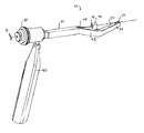
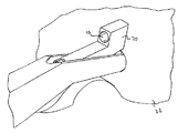
図1に示されるように、ドリルガイド10は、足部30と、ドリルガイド10を操作するためのハンドル40と、足部30とハンドル40との間の脚部50と、を含んでいる。図に示されるように、脚部50は、傾斜された部分42を含み、傾斜された部分42は足部30に向けて下向きに角度をつけられている。足部に対して角度をつけられた、傾斜された部分は、骨孔に向けて下向きに穿孔されている固定装置孔の可能性を増加する。
As shown in FIG. 1, the drill guide 10 includes a foot portion 30, a
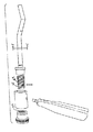
図2及び図3により具体的に示されるように、ドリルガイド10も、ロケータ70を制御するためのノブ60を有し、それによって、凹部44の内側及び外側にロケータを移動させる。ロケータ70が凹部44内に配置された場合、脚部50及び足部30は、脚部50から、又は脚部50の外側に分離される場合より、身体部位に容易に挿入され、身体部位は、外皮、組織、筋肉及び同様のものを含み、それら全ては切断され、それによってロケータ70が骨22に到達する。凹部44及び傾斜された部分42の内部のロケータ70と共に、ドリルガイド10は、本質的に単一の部材であり、すなわち脚部50であるので、2つの部材、すなわち互いに分離可能であり、又は少なくとも一の部材が他の部材内に配置されていない脚部50及びロケータ70を有するドリルガイドを操作するより、容易に操作される。凹部44内にロケータ70を配置することの他の利点は、単一の切断、及び同様に小さい切断が身体部位に行われることである。
2 and 3, the drill guide 10 also has a
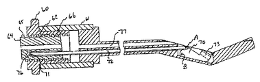
図に示されるように、ねじ部62は、アダプター64と係合され、アダプター64は、シャフト72に接続される。それによって、ノブ60の回転は、アダプター64の並進移動を引き起こし、且つアダプター64の並進運動は、順にシャフト72の軸方向の移動を引き起こす。
As shown in the figure, the threaded portion 62 is engaged with an
図6に示されるように、ノブ60のねじ部62は、アダプター64のねじ部65とねじ式に係合する、又は組み合わせる。しかしながら、そのような移動を妨げるシャフト72のために、ノブ60とアダプター64との間の回転移動がない、又は回転移動が無視でき、シャフト72が下部溝76を介して脚部50及びアダプター64を通じて延在する。ノブ60とアダプター64との間のねじ係合により妨げられた回転移動があるので、従って、ノブ60が回転される場合、アダプター64は、軸方向に移動する。
As shown in FIG. 6, the threaded portion 62 of the
アダプター64がノブ60に対して軸方向に移動する場合、シャフト72がピン71を介してアダプター64に固定される、又ピン留めされるので、シャフト72もノブ60に対して軸方向に移動する。他の実施形態において、ピン71は、リベット、ファスナー、又は同様のものに置き換える。
When the
ノブ60は、横ピン66を介して適所に保持され、この横ピン66はノブ60及びハウジング68を共に固着し、且つノブ60とハウジング68との間の軸方向の移動を妨げるが、ノブ60とハウジング68との間の回転移動を可能にする。いくつかの実施形態において、横ピン66は、ハウジング68をノブ60に固着するが、ベアリング、スナップリング、又はブッシングなどのハウジング68に対してノブ60の回転移動を可能にする任意の構造によって置き換えられる。
The
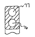
図に示されるように、下部溝76は、アダプターを通じて穿孔された孔であり、傾斜された部分42を通じて貫通孔であり、この穿孔された孔及び貫通孔は、互いに位置合わせする。いくつかの実施形態において、下部溝76は、アダプター64に示された穿孔された孔ではなく、一端から他端まで延在する代わりのものであり、又は上部溝77に類似の貫通孔である。下部溝76の要求された全てことは、シャフト72を収容するのに十分長い長さを有することである。図に示されるように、上部溝77は、アダプター64及び脚部50のそれぞれを貫通する貫通孔であり、それらの貫通孔は、互いに位置合わせされる。
As shown in the figure, the lower groove 76 is a hole drilled through the adapter, and is a through hole through the
ドリルガイド10の操作は、凹部44から完全に延在された位置にロケータ70を上昇するという目的のためであり、それによって、(図12に図示する)ガイドワイヤ75が骨22内の(図11に図示する)固定装置孔24を穿孔するために、貫通孔73を通過した後で、適所に配置される。
The manipulation of the drill guide 10 is for the purpose of raising the
図2に示されるように、骨孔21は、任意の周知の方法又は新規の方法で骨22内に穿孔される。足部30は、脚部50が骨22に接触する状態になるまで、骨孔21(図8)内に配置される。一旦この位置に配置されると、使用者は、ノブ60を回転させ、それによって、凹部44から、図9に示される、引き込まれていない位置へロケータ70を外側に上昇させる(ロケータ70はより詳細に以下に記載される。)。上記で議論されるように、次いで、ガイドワイヤ75は、ロケータ70内の貫通孔73を通過し、固定装置孔24(図10)の穿孔を開始する。
As shown in FIG. 2, the
上記のように、使用者は、ノブ60を回転させ、それによってロケータ64、及びそれ故にシャフト72が軸方向に移動し、シャフト72の軸方向の移動は、ロケータ70を位置Bに関して回転され、それによってそのような回転は、ロケータ70が凹部44を完全に引き込まれていない位置に向けて外側に延在するという結果を生じる。
As described above, the user rotates
図4,6,及び7に示されるように、ロケータ70は、位置Aでシャフト72にヒンジ接続され、それによって、ピン、リベット、及び同様のものは、ロケータ70及びシャフト72を互いに固着するように位置Aで配置され、ロケータ及びシャフト72は、互いに対して自由に回転する。同様に示されるように、ロケータ70は、傾斜された部分42に位置Bでヒンジ接続されるように取り付けられ、それによって、位置Bは位置Aと同一の制限を含む。この様式において、シャフト72の軸方向の並進移動は、ロケータ70を位置Bに関して回転させ、又は回動させ、それによって、シャフト72の並進移動、又は引張力/張力は、ヒンジ接続された位置Aでロケータ70に伝達される。ロケータ70が位置Bに関して回転されるにつれて、ロケータ70は、凹部44から上方向且つ外側に上昇される(図7に示される矢印によって表された回転方向を示す。)。
4, 6, and 7,
図8に示されるように、完全に引き込まれた位置において、ロケータ70は、傾斜された部分42の内部内に完全にある。図9に示されるように、完全に引き込まれていない位置において、ロケータ70は、凹部44から外側に延在する。引き込まれていない位置から引き込まれた位置へロケータ70を回転するために、ノブ60は、隣接した段落(immediate paragraph)からの反対側の方向に回転し、シャフト72を反対の方向に並進移動させ、それによって、圧縮力/押し込み力は、ヒンジ接続された位置Aでロケータ70に伝達される。圧縮力は、ロケータ70を位置Bに関して回転させる。
As shown in FIG. 8, in the fully retracted position, the
固定装置孔24と骨孔21との間の距離は、図11においてHによって表され、一般的に約3mmと約6mmとの間であり、より好ましくは、約4mmと約5mmとの間である。いくつかの実施形態において、距離Hは、距離Hが骨楔(bone wedge)の大きさを一般に規定するので、重要であり、一般的に固定装置孔24と骨孔21との間の骨楔と呼ぶ。固定装置からの圧力を受けている場合、小さい距離Hは、薄く、且つ容易に割れ目を生じさせる骨楔に導かれることができる。大きい距離Hは、骨楔を切断することを困難に導く。それ故に、固定装置孔24と骨孔21との間の適切な距離を維持することは、上述された範囲内で所望される。
The distance between the
この目的のために、ノブ60の回転数とロケータ70の高さHとの間の関係は、周知である。この関係は、ノブ60のねじ部62、シャフト72の長さ、ヒンジ接続部Aの位置、ヒンジ接続部Bの配置、及び傾斜された部分42の角度を含む。ドリルガイド10の製造中に、この関係におけるそれらの要因のうちの全ての要因は、周知である。従って、距離Hは、ノブ60の任意の付与された回転に対して周知である。
For this purpose, the relationship between the rotational speed of the
より具体的には、いくつかの実施形態において、ロケータ70の回転に対するノブ60の回転の割合は、18:1である。それ故に、ノブ60の18°ごとの回転に対して、ロケータ70は、凹部44からの外側方向に位置Aに関して1°回転する。
More specifically, in some embodiments, the ratio of rotation of
いくつかの上記の実施形態において、端部から端部までのドリルガイド10の(図7でTLとして示される)合計の長さは、約6.5インチであり、(L2として示される)ノブ60及び外側ブッシング61の長さは、約1.5インチであり、(L3として示される)外側ブッシング61の端部から位置Aまでのドリルガイド10の長さは、約3.394インチであり、(φ1として示される)ノブ60の最外径は、約1インチであり、(φ2として示される)アダプター64の外径は、約0.5インチであり、アダプター及びノブのピッチ62、65は、1インチあたり約10個のねじ山である。 In some of the above embodiments, the total length of the drill guide 10 from end to end (shown as TL in FIG. 7) is about 6.5 inches and knob (shown as L2). The length of 60 and outer bushing 61 is about 1.5 inches, and the length of drill guide 10 from the end of outer bushing 61 (shown as L3) to position A is about 3.394 inches. , The outermost diameter of the knob 60 (shown as φ1) is about 1 inch, the outer diameter of the adapter 64 (shown as φ2) is about 0.5 inch, and the adapter and knob pitches 62, 65 Is about 10 threads per inch.
さらなる実施形態において、ノブ60の一回の完全な回転は、シャフト72が約0.100インチ並進移動することを意味する。図に示されるように、シャフトの合計の軸方向の移動は、約0.075インチであり、ノブ60が約270°回転することを意味する。
In a further embodiment, one full rotation of the
他の実施形態において、位置Aと位置Bとの間の横方向の距離は、約0.133インチであり、シャフト72の0.023インチごとの軸方向の移動に対して、ロケータ70が約1°回転することを意味する。好ましい実施形態において、ロケータ70は、完全な延在位置と完全な引き込まれた位置との間で合計約27°回転する。0.023インチ×27°の積のは、0.062インチと同等であり、それは、ロケータ70の近似の軸方向の移動を表す。
In another embodiment, the lateral distance between position A and position B is about 0.133 inches, and for axial movement of shaft 72 every 0.023 inches,
0.075インチと0.062インチとの間の差(0.013インチ)は、ノブ60から位置Bに達する(stack up)のために、横方向における偏位(又は、傾斜、又は測定誤差)の基準を表す。これは、約15°が必要とされる全てである場合に、ロケータ70の約27°の回転の理由であり、この約15°は、足部30に対する傾斜された部分42のおよその角度の関係である。約27°の回転は、約0.013インチのスロップ(slop)を補償することであり、ロケート70の過剰な回転は、完全に引き込まれた位置及び完全に延在された位置が遭遇されることを確実にする。理想的な環境下で、横方向において任意の0.013インチの測定誤差があることはなく、それ故に、横方向の移動は、ロケータ70の約0.062インチの軸方向の移動であり、ロケータが15°を超えて回転する必要は無い。
The difference between 0.075 inch and 0.062 inch (0.013 inch) is a lateral deviation (or tilt, or measurement error) due to stack up from
さらなる実施形態において、ノブの回転を減少するために、割合は15:1、又は12:1に減少される。さらに別の実施形態において、割合は、10:1である。微細な回転が好まれる実施形態において、それによって、ロケータ70がわずかな角度で回転され、距離Hが10分の数インチ又は10分の数ミリメータで測定され、割合は、例えば25:1などの20:1から30:1の間に増加される。
In further embodiments, the ratio is reduced to 15: 1 or 12: 1 to reduce knob rotation. In yet another embodiment, the ratio is 10: 1. In an embodiment in which fine rotation is preferred, it causes the
ノブの回転を減少するための他の方法は、例えば1インチあたり8ねじ山になるように、ねじ部のピッチ62,65を減少することである。その結果は、約半回転、又は約180°の減少されたノブの回転である。逆に、ピッチを増大することは、上記の微細な回転を達成する。 Another way to reduce the rotation of the knob is to reduce the thread pitch 62, 65, for example to 8 threads per inch. The result is about a half turn or a reduced knob turn of about 180 °. Conversely, increasing the pitch achieves the fine rotation described above.
いくつかの実施形態において、距離Hは、ロケータ7が完全に引き込まれた位置にある場所又はロケータ70が完全に引き込まれていない位置にある場所で固定され、完全に引き込まれた位置にある場所と完全に引き込まれていない位置である場所との間の任意の位置にあることはない。使用者にノブ60を回転するのを停止するときを知らせるノブ60上の機械的停止部が存在し、回転がこのポイントに到達することは、ロケータ70が凹部44から完全に延在することを意味する。
In some embodiments, the distance H is fixed at a location where the locator 7 is in a fully retracted position or a location where the
他の実施形態において、ドリルガイド10の使用者は、完全に引き込まれた位置と完全に引き込まれていない位置との間の位置に距離Hを変えることを望む。ノブ60の回転とロケータ70の回転との間の関係なので、距離Hが周知である。それ故に、特定の距離Hを所望する使用者は、どのくらいの回転が必要であるか、及びどのくらいの回転がその回転に対してノブ60を回転することを知っている。逆もまた同様に、ノブ60を回転させる人は、多くの回転後の距離H、すなわち完全に引き込まれた位置と完全に引き込まれていない位置との間の所望される距離が達成され、次いでノブ60を回転することを停止することを知っている。
In other embodiments, the user of the drill guide 10 desires to change the distance H to a position between a fully retracted position and a position that is not fully retracted. The distance H is well known because of the relationship between the rotation of the
いくつかの実施形態において、ノブ60を回転すると同時に、距離Hは、ディスプレイ又は距離Hの表示器のために常に知られている。それ故に、使用者は、いつノブ60を回転することを停止するのかを知る。それらのいくつかの実施形態において、表示器又はディスプレイは、ノブ60の回転を単に測定し、一般的に中央で骨孔21に対するロケータ70の相対的な距離を計算する。
In some embodiments, the distance H is always known for the display or indicator of distance H while rotating the
ねじ部62の細かさ、又はねじ部が互いにどれくらい近接しているかは、シャフト72の軸方向の並進移動に影響を及ぼす。ねじ部がより細かければ細かいほど、ますます軸方向の並進移動は遅くなり、それ故に、ノブ60のより多い回転数は、粗雑なねじ付きのノブよりシャフト72を並進移動することを必要とされる。付加的に、ねじ山がより細かければ細かいほど、より精密な距離H又はより正確な距離Hが使用者によって設定されることができ、特に距離Hが10分の数インチ、100分の数インチ、及び同様な程度まで測定される場合に、使用者によって設定されることができる。
The fineness of the threaded portion 62 or how close the threaded portions are to each other affects the translational movement of the shaft 72 in the axial direction. The finer the thread, the more slowly the axial translation is slower, and therefore the higher rotational speed of the
所望される距離が達成され、且つロケータ70が引き込まれていない位置にある場合(代替実施形態で上述されたように、必ずしも完全に引き込まれていない位置を意味するとは限らない。)、ガイドワイヤ75は、アダプター64を通じて上部溝77に挿入され、脚部50を貫通し、骨22に向けてロケータ70の貫通孔73を貫通する。これは図10に図示される。骨22を接触した後に、ガイドワイヤ75は、骨22内に穿孔するように回転され、それによって、骨22を通じて固定装置孔24を設ける。
If the desired distance is achieved and the
図示されるように、固定装置孔は、止まり穴(blind hole)であってもよく、使用者が視覚的に決定することができなく、又はガイドワイヤ75の端部での視覚的な接触を減少させることができない。それによって、固定装置孔24が完成される場合、又は骨22が完全に貫通されている場合に、決定する困難さを有する。
As shown, the fixation device hole may be a blind hole and cannot be visually determined by the user, or visual contact at the end of the
いくつかの実施形態において、ガイドワイヤ75は、ガイドワイヤ75が足部30、より具体的には足部30の溝32及びノッチ33に接触する状態になるまで、骨22を貫通し続ける。溝32は、ガイドワイヤ75を受容し、横方向における足部30を斜めにする、又は足部30をはずすガイドワイヤ75の可能性を低減する。さらに、溝32がノッチ33に向けてガイドワイヤ75を方向付け、いくつかの実施形態において、センサが、ガイドワイヤ75との接触を検出するためにノッチ33に配置される。センサがガイドワイヤ75を検出すると、信号は、ガイドワイヤ75がノッチ33及び/又は溝32に接触した状態であり、それ故に骨22を通じて貫通していることを使用者に表示するために、使用者に対して近位の受信機に送られる。さらなる他の実施形態において、センサは、ガイドワイヤ75の材料である金属に対する感度が良い。それらのいくつかの実施形態において、センサは、骨22に接触させるガイドワイヤ75を視覚的に検出する。他の実施形態において、本発明は、ガイドワイヤ75が骨を貫通し、固定装置孔24が完成したことを使用者に知らせるための他の手段を想像する。
In some embodiments, the
本発明の他の態様において、図13は、骨22内で骨孔21に近接して提案された固定装置孔を配置するために、図1に示されたガイドワイヤを提供するための方法100を描写し、方法100は、骨孔内に配置するための足部を提供するステップ102、足部から脚部を延在するステップ104、脚部内の凹部を配置するステップ106、及び凹部内の引き込まれた位置であるロケータを配置するステップ110を含んでいる。それらのいくつかの態様において、脚部は、骨孔に向けて所定の角度で固定装置孔をより良く位置付けるために、脚部から角度をつけて延在されている108。
In another aspect of the present invention, FIG. 13 shows a
方法100はまた、ロケータが引き込まれた位置から引き込まれていない位置に凹部の内側及び外側で回動することを可能にするために、脚部にロケータをヒンジ接続するステップ112を含み、引き込まれていない位置は、ロケータが回転し、凹部から外側に延在する位置である。
The
方法100はまた、提案された固定装置孔と骨孔との間の距離を変えるためのロケータを制御するステップ116を有する。いくつかの実施形態において、このステップは、脚部内に配置されたシャフトと共にロケータを回動可能に接続するステップ118、及びノブの回転はロケータを凹部の内側及び外側で回動させ、ロケータと反対側のシャフトにねじ山を切られたノブを接続するステップ122を含む。
The
さらなる実施形態において、ロケータを制御することはまた、提案された固定装置孔と骨孔との間の距離に応じてノブの回転数を決定するステップ124を含む。他の実施形態において、これは、軸方向でシャフトを並進移動し、且つ脚部とのヒンジ接続、又は脚部との回動可能な接続に関してロケータを回転するステップ126を含む。 In a further embodiment, controlling the locator also includes determining 124 the number of rotations of the knob as a function of the distance between the proposed fixation device hole and the bone hole. In other embodiments, this includes the step 126 of axially translating the shaft and rotating the locator with respect to a hinge connection with the leg or a pivotable connection with the leg.
10 ドリルガイド
30 足部
32 溝
33 ノッチ
40 ハンドル
42 傾斜された部分
44 凹部
50 脚部
60 ノブ
61 外側ブッシング
62 ねじ部(ピッチ)
64 アダプター
65 ねじ部(ピッチ)
66 横ピン
70 ロケータ
71 ピン
72 シャフト
73 貫通孔
75 ガイドワイヤ
76 下部溝
77 上部溝
A 位置
B 位置
H 固定装置孔24と骨孔21との間の距離
TL ドリルガイドの合計の長さ
L2 ノブ60及び外側ブッシング61の長さ
L3 外側ブッシング61の端部から位置Aまでのドリルガイド10の長さ
φ1 ノブ60の最大径
φ2 アダプター64の外径
DESCRIPTION OF SYMBOLS 10 Drill guide 30
64 Adapter 65 Thread part (pitch)
66
Claims (13)
前記骨の骨孔内での配置のための足部と、
前記足部から延在し、且つ凹部を有する脚部と、
前記凹部内に配置されたロケータであって、引き込まれた位置で、完全に前記脚部の内側にある前記ロケータと、
を備えているドリルガイドであって、
引き込まれていない位置で、前記ロケータが前記固定装置孔を配置するための前記凹部から外側に回転し、且つ外側に延在するように、前記ロケータは、前記脚部にヒンジ接続されていることを特徴とするドリルガイド。 A drill guide for positioning a fixation device hole proximate to a bone hole in a bone,
A foot for placement in the bone hole of the bone;
A leg extending from the foot and having a recess;
A locator disposed in the recess, in retracted position, said locator completely inside the front Kiashi portion,
A drill guide comprising:
The locator is hinged to the leg so that, in an unretracted position, the locator rotates outwardly from and extends outwardly from the recess for positioning the fixing device hole. A drill guide characterized by
前記骨の骨孔内での配置のための足部と、
前記足部から延在し、かつ凹部を有する脚部と、
前記凹部内に配置されたロケータであって、引き込まれた位置で、前記脚部の内側にある前記ロケータと、
第1の位置で前記脚部にヒンジ接続された前記ロケータであって、引き込まれていない位置で、前記ロケータは、前記固定装置孔を配置するための前記凹部から外側に回転し、且つ外側に延在する前記ロケータと、
第2の位置でシャフトにヒンジ接続された前記ロケータと、
を備えているドリルガイドであって、
前記足部から離れる前記シャフトの移動は、前記第2の位置を介して前記ロケータに引張力を伝達し、前記ロケータを前記引き込まれていない位置へ前記第1の位置に関して回転させ、
前記足部に向けて前記シャフトの移動は、前記ロケータに圧縮力を伝達し、前記ロケータを前記引き込まれた位置へ前記第1の位置に関して回転させることを特徴とするドリルガイド。 A drill guide for positioning a fixation device hole proximate to a bone hole in a bone,
A foot for placement in the bone hole of the bone;
A leg extending from the foot and having a recess;
A locator disposed in the recess, wherein the locator is inside the leg at the retracted position;
The locator hinged to the leg in a first position, wherein the locator rotates outwardly from the recess for placing the fixing device hole and outwards in an unretracted position; The locator extending; and
The locator hinged to the shaft at a second position;
A drill guide comprising:
Movement of the shaft away from the foot transmits a tensile force to the locator via the second position, rotates the locator relative to the first position to the unretracted position;
The drill guide characterized in that the movement of the shaft toward the foot transmits a compressive force to the locator and rotates the locator relative to the first position to the retracted position.
Applications Claiming Priority (2)
| Application Number | Priority Date | Filing Date | Title |
|---|---|---|---|
| US11/759,036 US7815646B2 (en) | 2007-06-06 | 2007-06-06 | Drill guide and method for placing a fixation device hole |
| US11/759,036 | 2007-06-06 |
Publications (2)
| Publication Number | Publication Date |
|---|---|
| JP2008302227A JP2008302227A (en) | 2008-12-18 |
| JP4773483B2 true JP4773483B2 (en) | 2011-09-14 |
Family
ID=39926745
Family Applications (1)
| Application Number | Title | Priority Date | Filing Date |
|---|---|---|---|
| JP2008148506A Expired - Fee Related JP4773483B2 (en) | 2007-06-06 | 2008-06-05 | Drill guide and method for positioning a fixing device hole |
Country Status (6)
| Country | Link |
|---|---|
| US (2) | US7815646B2 (en) |
| EP (1) | EP2005905B1 (en) |
| JP (1) | JP4773483B2 (en) |
| AT (1) | ATE504246T1 (en) |
| CA (1) | CA2633219C (en) |
| DE (1) | DE602008005955D1 (en) |
Families Citing this family (41)
| Publication number | Priority date | Publication date | Assignee | Title |
|---|---|---|---|---|
| US7892229B2 (en) | 2003-01-18 | 2011-02-22 | Tsunami Medtech, Llc | Medical instruments and techniques for treating pulmonary disorders |
| US8016823B2 (en) | 2003-01-18 | 2011-09-13 | Tsunami Medtech, Llc | Medical instrument and method of use |
| US9433457B2 (en) | 2000-12-09 | 2016-09-06 | Tsunami Medtech, Llc | Medical instruments and techniques for thermally-mediated therapies |
| US8579892B2 (en) | 2003-10-07 | 2013-11-12 | Tsunami Medtech, Llc | Medical system and method of use |
| US20110077628A1 (en) * | 2006-01-10 | 2011-03-31 | Tsunami Medtech, Llc | Medical system and method of use |
| ATE505147T1 (en) | 2007-08-23 | 2011-04-15 | Aegea Medical Inc | UTERUS THERAPY DEVICE |
| US8771273B2 (en) | 2007-12-17 | 2014-07-08 | Karl Storz Gmbh & Co. Kg | Surgical drill for providing holes at an angle |
| US9826992B2 (en) | 2007-12-21 | 2017-11-28 | Smith & Nephew, Inc. | Multiple portal guide |
| JP5818438B2 (en) | 2007-12-21 | 2015-11-18 | スミス アンド ネフュー インコーポレーテッドSmith & Nephew,Inc. | Many portal guides |
| US9924992B2 (en) | 2008-02-20 | 2018-03-27 | Tsunami Medtech, Llc | Medical system and method of use |
| US8282647B2 (en) * | 2008-02-21 | 2012-10-09 | Tyco Healthcare Group Lp | Femoral guide for ACL repair having adjustable offset |
| US8721632B2 (en) | 2008-09-09 | 2014-05-13 | Tsunami Medtech, Llc | Methods for delivering energy into a target tissue of a body |
| US9017329B2 (en) * | 2008-06-24 | 2015-04-28 | Extremity Medical, Llc | Intramedullary fixation assembly and method of use |
| US8313487B2 (en) | 2008-06-24 | 2012-11-20 | Extremity Medical Llc | Fixation system, an intramedullary fixation assembly and method of use |
| US8328806B2 (en) | 2008-06-24 | 2012-12-11 | Extremity Medical, Llc | Fixation system, an intramedullary fixation assembly and method of use |
| US8343199B2 (en) | 2008-06-24 | 2013-01-01 | Extremity Medical, Llc | Intramedullary fixation screw, a fixation system, and method of fixation of the subtalar joint |
| US8303589B2 (en) * | 2008-06-24 | 2012-11-06 | Extremity Medical Llc | Fixation system, an intramedullary fixation assembly and method of use |
| US9289220B2 (en) | 2008-06-24 | 2016-03-22 | Extremity Medical Llc | Intramedullary fixation assembly and method of use |
| US9044282B2 (en) * | 2008-06-24 | 2015-06-02 | Extremity Medical Llc | Intraosseous intramedullary fixation assembly and method of use |
| US11284931B2 (en) | 2009-02-03 | 2022-03-29 | Tsunami Medtech, Llc | Medical systems and methods for ablating and absorbing tissue |
| US8900223B2 (en) | 2009-11-06 | 2014-12-02 | Tsunami Medtech, Llc | Tissue ablation systems and methods of use |
| US9943353B2 (en) | 2013-03-15 | 2018-04-17 | Tsunami Medtech, Llc | Medical system and method of use |
| CN103429178A (en) | 2010-09-27 | 2013-12-04 | 史密夫和内修有限公司 | Device and methods for use during arthroscopic surgery |
| WO2012061639A1 (en) | 2010-11-03 | 2012-05-10 | Smith & Nephew, Inc. | Drill guide |
| WO2012064864A1 (en) | 2010-11-09 | 2012-05-18 | Aegea Medical Inc. | Positioning method and apparatus for delivering vapor to the uterus |
| US8690885B2 (en) | 2011-01-28 | 2014-04-08 | Smith & Nephew, Inc. | Surgical aiming device |
| US9545261B2 (en) | 2011-07-29 | 2017-01-17 | Smith & Nephew, Inc. | Instrument guide |
| US9918723B2 (en) | 2011-09-23 | 2018-03-20 | Depuy Mitek, Llc | Glenoid anchor guide |
| CN104135960B (en) | 2011-10-07 | 2017-06-06 | 埃杰亚医疗公司 | A kind of uterine therapy device |
| US20140081281A1 (en) * | 2012-09-14 | 2014-03-20 | DePuy Synthes Products, LLC | Multihole Drill Sleeve with Protection Sleeve |
| US9642629B2 (en) * | 2012-11-20 | 2017-05-09 | Specialty Surgical Instrumentation Inc. | System and method for forming a curved tunnel in bone |
| US20150216541A1 (en) * | 2014-02-03 | 2015-08-06 | Arthrex, Inc. | Pointing device and drilling tool |
| CN103932795B (en) * | 2014-04-10 | 2015-12-30 | 中国人民解放军第四军医大学 | The femoral bone tunnel dial-type localizer of Healing in Anterior Cruciate Ligament Reconstruction under arthroscope |
| WO2015179666A1 (en) | 2014-05-22 | 2015-11-26 | Aegea Medical Inc. | Systems and methods for performing endometrial ablation |
| EP3145426B1 (en) | 2014-05-22 | 2023-03-22 | Aegea Medical, Inc. | Apparatus for delivering vapor to the uterus |
| US10357314B2 (en) | 2015-07-08 | 2019-07-23 | Stryker European Holdings I, Llc | Instrumentation and method for repair of a bone fracture |
| USD791944S1 (en) * | 2016-02-03 | 2017-07-11 | Mcginley Engineered Solutions, Llc | Drill guide |
| WO2017143343A1 (en) | 2016-02-19 | 2017-08-24 | Aegea Medical Inc. | Methods and apparatus for determining the integrity of a bodily cavity |
| WO2020076376A1 (en) * | 2018-10-12 | 2020-04-16 | Conmed Corporation | Drill guide assembly |
| USD998792S1 (en) * | 2019-10-01 | 2023-09-12 | Think Surgical, Inc. | Digitizer |
| US20230103416A1 (en) * | 2021-10-01 | 2023-04-06 | Ronald Yamada | System and method for soft tissue and bone repair |
Family Cites Families (46)
| Publication number | Priority date | Publication date | Assignee | Title |
|---|---|---|---|---|
| US2547571A (en) * | 1950-06-02 | 1951-04-03 | Zimmer Mfg Company | Hip fracture drill guide |
| US4672957A (en) * | 1983-10-04 | 1987-06-16 | South African Inventions Development Corporation | Surgical device |
| US4722331A (en) * | 1985-09-03 | 1988-02-02 | Fox James M | Orthopaedic tool guide |
| US4669473A (en) * | 1985-09-06 | 1987-06-02 | Acufex Microsurgical, Inc. | Surgical fastener |
| US4733654A (en) * | 1986-05-29 | 1988-03-29 | Marino James F | Intramedullar nailing assembly |
| US4781182A (en) * | 1986-10-03 | 1988-11-01 | Purnell Mark L | Apparatus and method for use in performing a surgical operation |
| US4739751A (en) * | 1986-10-03 | 1988-04-26 | Temple University | Apparatus and method for reconstructive surgery |
| US4920958A (en) * | 1986-11-05 | 1990-05-01 | Minnesota Mining And Manufacturing Company | Drill guide assembly |
| US4911153A (en) * | 1988-02-04 | 1990-03-27 | Biomet, Inc. | Orthopedic surgical instrument |
| US4901711A (en) * | 1988-12-27 | 1990-02-20 | Marlowe Goble E | Drill guide |
| US4950271A (en) * | 1989-02-06 | 1990-08-21 | Regents Of The University Of Minnesota | Ligament graft apparatus and method |
| US5026376A (en) * | 1990-07-13 | 1991-06-25 | Greenberg Alex M | Surgical drill guide and retractor |
| US5300077A (en) * | 1990-07-16 | 1994-04-05 | Arthrotek | Method and instruments for ACL reconstruction |
| US6254604B1 (en) * | 1990-07-16 | 2001-07-03 | Arthrotek, Inc. | Tibial guide |
| US6019767A (en) * | 1990-07-16 | 2000-02-01 | Arthrotek | Tibial guide |
| US5385567A (en) * | 1990-09-07 | 1995-01-31 | Goble; E. Marlowe | Sight barrel arthroscopic instrument |
| US5112337A (en) * | 1991-02-05 | 1992-05-12 | Depuy Du Pont Orthopaedics | Variable angle, selective length tibial drill guide |
| US5163940A (en) * | 1991-03-04 | 1992-11-17 | American Cyanamid Company | Surgical drill guide for tibia |
| US5683400A (en) * | 1991-12-13 | 1997-11-04 | Mcguire; David A. | Graft preparation table |
| US5681320A (en) * | 1991-12-13 | 1997-10-28 | Mcguire; David A. | Bone-cutting guide |
| GB9202561D0 (en) * | 1992-02-07 | 1992-03-25 | Howmedica | Orthopaedic instrument |
| US5154720A (en) * | 1992-02-19 | 1992-10-13 | Linvatec Corporation | Surgical drill guide |
| US5320626A (en) * | 1992-02-19 | 1994-06-14 | Arthrex Inc. | Endoscopic drill guide |
| US5562664A (en) * | 1992-02-20 | 1996-10-08 | Arthrex Inc. | Drill guide with target PCL-oriented marking hook |
| US5350383A (en) * | 1992-02-20 | 1994-09-27 | Arthrex, Inc. | Adjustable drill guide with interchangeable marking hooks |
| US5324295A (en) * | 1992-04-24 | 1994-06-28 | Shapiro Michael R | Drill guide for surgical pins |
| US5234434A (en) * | 1992-08-17 | 1993-08-10 | Marlowe Goble E | Mutliple guide sleeve drill guide |
| US5330468A (en) * | 1993-10-12 | 1994-07-19 | Burkhart Stephen S | Drill guide device for arthroscopic surgery |
| US5514144A (en) * | 1993-12-20 | 1996-05-07 | Bolton; Carl W. | Drill guide device for the arthroscopic anatomic placement of a straight tibio-femoral bone tunnel for ACL reconstruction |
| US5458602A (en) * | 1994-01-11 | 1995-10-17 | Mitek Surgical Products, Inc. | Surgical drill guide |
| US5601566A (en) * | 1994-02-22 | 1997-02-11 | Osteonics Corp. | Method and apparatus for the alignment of a femoral knee prosthesis |
| US5601550A (en) * | 1994-10-25 | 1997-02-11 | Esser; Rene D. | Pelvic pin guide system for insertion of pins into iliac bone |
| US5584839A (en) * | 1994-12-12 | 1996-12-17 | Gieringer; Robert E. | Intraarticular drill guide and arthroscopic methods |
| US5643273A (en) * | 1995-02-17 | 1997-07-01 | Clark; Ron | ACL bone tunnel projection drill guide and method for its use |
| DE29504857U1 (en) * | 1995-03-22 | 1995-05-18 | Aesculap Ag | Drilling jig for surgical drilling tools |
| US5613971A (en) * | 1995-08-11 | 1997-03-25 | Depuy Inc. | Ratcheting tibial and femoral guide |
| US5688284A (en) * | 1996-09-20 | 1997-11-18 | Medicinelodge, Inc. | Variable angle drill guide and ligament fixation method |
| US5891150A (en) * | 1996-12-04 | 1999-04-06 | Chan; Kwan-Ho | Apparatus and method for fixing a ligament in a bone tunnel |
| US6120511A (en) * | 1997-11-18 | 2000-09-19 | Chan; Kwan-Ho | Drill guide assembly and method for producing a bone tunnel |
| US5968050A (en) * | 1997-12-05 | 1999-10-19 | Smith & Nephew, Inc. | Positioning a tibial tunnel |
| US6210415B1 (en) * | 2000-02-18 | 2001-04-03 | Lab Engineering & Manufacturing, Inc. | Surgical drill guide |
| US6342057B1 (en) * | 2000-04-28 | 2002-01-29 | Synthes (Usa) | Remotely aligned surgical drill guide |
| US6547795B2 (en) * | 2001-08-13 | 2003-04-15 | Depuy Acromed, Inc. | Surgical guide system for stabilization of the spine |
| US7575578B2 (en) * | 2002-02-13 | 2009-08-18 | Karl Storz Gmbh & Co. Kg | Surgical drill guide |
| AU2003226382A1 (en) * | 2002-04-12 | 2003-10-27 | Eric S. Steenlage | Method and apparatus for reconstructing a ligament |
| US7004947B2 (en) * | 2002-06-24 | 2006-02-28 | Endius Incorporated | Surgical instrument for moving vertebrae |
-
2007
- 2007-06-06 US US11/759,036 patent/US7815646B2/en not_active Expired - Fee Related
-
2008
- 2008-06-03 CA CA2633219A patent/CA2633219C/en not_active Expired - Fee Related
- 2008-06-05 JP JP2008148506A patent/JP4773483B2/en not_active Expired - Fee Related
- 2008-06-05 EP EP08010257A patent/EP2005905B1/en not_active Not-in-force
- 2008-06-05 DE DE602008005955T patent/DE602008005955D1/en active Active
- 2008-06-05 AT AT08010257T patent/ATE504246T1/en not_active IP Right Cessation
-
2009
- 2009-07-21 US US12/506,582 patent/US7927340B2/en not_active Expired - Fee Related
Also Published As
| Publication number | Publication date |
|---|---|
| CA2633219A1 (en) | 2008-12-06 |
| EP2005905A1 (en) | 2008-12-24 |
| US20090287219A1 (en) | 2009-11-19 |
| ATE504246T1 (en) | 2011-04-15 |
| US20080306487A1 (en) | 2008-12-11 |
| CA2633219C (en) | 2012-01-03 |
| US7815646B2 (en) | 2010-10-19 |
| JP2008302227A (en) | 2008-12-18 |
| EP2005905B1 (en) | 2011-04-06 |
| US7927340B2 (en) | 2011-04-19 |
| DE602008005955D1 (en) | 2011-05-19 |
Similar Documents
| Publication | Publication Date | Title |
|---|---|---|
| JP4773483B2 (en) | Drill guide and method for positioning a fixing device hole | |
| TW381015B (en) | Device for making endochondral or osteochondral bores | |
| US11284877B2 (en) | Biceps tenodesis implants and delivery tools | |
| US7018383B2 (en) | Systems and methods for producing osteotomies | |
| US20180296319A1 (en) | Biceps Tenodesis Implants and Delivery Tools | |
| EP2138110B1 (en) | Adjustable orthopaedic drill guide | |
| US6267767B1 (en) | Instrumentarium and method for implanting a cruciate ligament replacement in a knee joint | |
| US20210059808A1 (en) | Method for anchoring biceps tenodesis | |
| EP2072015B1 (en) | Surgical drill for providing holes at an angle | |
| JP5770306B2 (en) | Surgical instruments | |
| JP2528588B2 (en) | Punching device for interengaging nail implantation | |
| EP2961337B1 (en) | Systems and apparatuses for reaming bone elements | |
| CA3105930C (en) | Adjustable drilling device and a method for use thereof | |
| EP1785103A1 (en) | Apparatus for anterior cruciate ligament (ACL) reconstruction using rotary drill cutter to form retrograde sockets | |
| US20060229621A1 (en) | Apparatus and methods for tibial plateau leveling osteotomy | |
| JP2019502523A (en) | Fracture repair device and method | |
| US7575579B2 (en) | Drill guide tissue protector | |
| CN101534731A (en) | Surgical cutting devices and methods | |
| JP4402029B2 (en) | Artificial knee joint installation jig | |
| US6780115B2 (en) | Method and system for intraoperatively revising the length of fracture fixation screws | |
| JP3781185B2 (en) | Fixed nail implantation system | |
| US20220361899A1 (en) | System and method for creating graft tunnels in bone | |
| JP2543483Y2 (en) | Acetabular resection device | |
| CN216603009U (en) | Articular surface locator for assisting in resetting and fixing articular surface collapse fracture | |
| ITVR970004A1 (en) | MECHANICAL EQUIPMENT FOR THE CENTERING OF BLIND HOLES FOR BONE SCREWS OF ENDOMIDOLLAR NAILS |
Legal Events
| Date | Code | Title | Description |
|---|---|---|---|
| A711 | Notification of change in applicant |
Free format text: JAPANESE INTERMEDIATE CODE: A711 Effective date: 20090731 |
|
| A521 | Request for written amendment filed |
Free format text: JAPANESE INTERMEDIATE CODE: A821 Effective date: 20090731 |
|
| A131 | Notification of reasons for refusal |
Free format text: JAPANESE INTERMEDIATE CODE: A131 Effective date: 20110222 |
|
| A521 | Request for written amendment filed |
Free format text: JAPANESE INTERMEDIATE CODE: A523 Effective date: 20110427 |
|
| A01 | Written decision to grant a patent or to grant a registration (utility model) |
Free format text: JAPANESE INTERMEDIATE CODE: A01 Effective date: 20110524 |
|
| A61 | First payment of annual fees (during grant procedure) |
Free format text: JAPANESE INTERMEDIATE CODE: A61 Effective date: 20110623 |
|
| FPAY | Renewal fee payment (event date is renewal date of database) |
Free format text: PAYMENT UNTIL: 20140701 Year of fee payment: 3 |
|
| R150 | Certificate of patent or registration of utility model |
Free format text: JAPANESE INTERMEDIATE CODE: R150 |
|
| R250 | Receipt of annual fees |
Free format text: JAPANESE INTERMEDIATE CODE: R250 |
|
| R250 | Receipt of annual fees |
Free format text: JAPANESE INTERMEDIATE CODE: R250 |
|
| R250 | Receipt of annual fees |
Free format text: JAPANESE INTERMEDIATE CODE: R250 |
|
| LAPS | Cancellation because of no payment of annual fees |