JP4773372B2 - Coating die, system for supplying material, and method of applying material to a moving substrate - Google Patents
Coating die, system for supplying material, and method of applying material to a moving substrate Download PDFInfo
- Publication number
- JP4773372B2 JP4773372B2 JP2006551120A JP2006551120A JP4773372B2 JP 4773372 B2 JP4773372 B2 JP 4773372B2 JP 2006551120 A JP2006551120 A JP 2006551120A JP 2006551120 A JP2006551120 A JP 2006551120A JP 4773372 B2 JP4773372 B2 JP 4773372B2
- Authority
- JP
- Japan
- Prior art keywords
- die
- applicator slot
- coating
- slot
- substrate
- Prior art date
- Legal status (The legal status is an assumption and is not a legal conclusion. Google has not performed a legal analysis and makes no representation as to the accuracy of the status listed.)
- Expired - Fee Related
Links
Images


Classifications
-
- B—PERFORMING OPERATIONS; TRANSPORTING
- B05—SPRAYING OR ATOMISING IN GENERAL; APPLYING FLUENT MATERIALS TO SURFACES, IN GENERAL
- B05C—APPARATUS FOR APPLYING FLUENT MATERIALS TO SURFACES, IN GENERAL
- B05C5/00—Apparatus in which liquid or other fluent material is projected, poured or allowed to flow on to the surface of the work
- B05C5/02—Apparatus in which liquid or other fluent material is projected, poured or allowed to flow on to the surface of the work the liquid or other fluent material being discharged through an outlet orifice by pressure, e.g. from an outlet device in contact or almost in contact, with the work
- B05C5/0254—Coating heads with slot-shaped outlet
-
- B—PERFORMING OPERATIONS; TRANSPORTING
- B05—SPRAYING OR ATOMISING IN GENERAL; APPLYING FLUENT MATERIALS TO SURFACES, IN GENERAL
- B05C—APPARATUS FOR APPLYING FLUENT MATERIALS TO SURFACES, IN GENERAL
- B05C5/00—Apparatus in which liquid or other fluent material is projected, poured or allowed to flow on to the surface of the work
- B05C5/02—Apparatus in which liquid or other fluent material is projected, poured or allowed to flow on to the surface of the work the liquid or other fluent material being discharged through an outlet orifice by pressure, e.g. from an outlet device in contact or almost in contact, with the work
-
- Y—GENERAL TAGGING OF NEW TECHNOLOGICAL DEVELOPMENTS; GENERAL TAGGING OF CROSS-SECTIONAL TECHNOLOGIES SPANNING OVER SEVERAL SECTIONS OF THE IPC; TECHNICAL SUBJECTS COVERED BY FORMER USPC CROSS-REFERENCE ART COLLECTIONS [XRACs] AND DIGESTS
- Y10—TECHNICAL SUBJECTS COVERED BY FORMER USPC
- Y10S—TECHNICAL SUBJECTS COVERED BY FORMER USPC CROSS-REFERENCE ART COLLECTIONS [XRACs] AND DIGESTS
- Y10S118/00—Coating apparatus
- Y10S118/02—Bead coater
Description
本発明は、概してコーティング装置および方法に関する。より詳細には、本発明は、プロセスの特徴を示すキャピラリー数が小さい場合での使用に適合したコーティング装置および方法に関する。 The present invention generally relates to coating apparatus and methods. More particularly, the present invention relates to a coating apparatus and method adapted for use with a small number of capillaries exhibiting process characteristics.
材料のウェブの上へのコーティングは良く知られている。このようなコーティングは、アプリケータースロットと連絡するキャビティを有するコーティングダイを使用して好都合に実施できることが多い。加圧下で液体がキャビティ内に導入され、次にアプリケータースロットから所望の基材上に押し出される。 Coating of material onto a web is well known. Such coatings can often be conveniently performed using a coating die having a cavity in communication with the applicator slot. Under pressure, liquid is introduced into the cavity and then extruded from the applicator slot onto the desired substrate.
望まれる厳密な結果に依存するが、この趣旨による変形例は多数存在し、種々のコーティングの補助が知られている。特に、ある種の条件下、特にコーティングダイを通過するウェブ速度が非常に速い場合には、アプリケータースロットから供給される材料が不規則に内側にくびれる場合があることが知られている。このくびれが発生するかどうかを予測することができるパラメータの1つが、コーティングプロセスの特徴を示すいわゆる「キャピラリー数」である。 Depending on the exact results desired, there are many variations to this effect and various coating aids are known. In particular, it is known that under certain conditions, especially when the web speed through the coating die is very high, the material delivered from the applicator slot may be randomly constricted inwardly. One parameter that can predict whether this necking will occur is the so-called “capillary number”, which characterizes the coating process.
キャピラリー数は:

Capillaries are:
この供給される材料が内側に引っ張られる傾向を制御するための種々の手段が当業者には周知となっている。当技術分野においては、供給される材料を予測可能な幅に戻すための機械的補助は多数存在する。これらは、文献においては「エッジガイド」と呼ばれることが多い。これらは特にスライドコーティングおよびカーテンコーティングの説明において見られる。 Various means are well known to those skilled in the art for controlling the tendency of the supplied material to be pulled inward. There are many mechanical aids in the art to return the supplied material to a predictable width. These are often called “edge guides” in the literature. These are especially seen in the description of slide coating and curtain coating.
しかし、反対の問題と見なしうることについては文献には書かれていない。最近、非常に低速において非常に薄い乾燥した層で高い値の材料(基材)をコーティングしようとすると、アプリケータースロットの末端におけるダイ表面と基材との間の間隙に沿って毛管力が供給された材料を側方に引っ張るため、不規則な幅のコーティングとなるという結果が得られている。高い値の材料(high value materials)上にコーティングされる薄い乾燥した層は、基材に供給するために溶媒で希釈されることによって、基材に供給されるコーティングと溶媒との混合物の粘度が低下し、コーティング厚さが増加するためである。 However, the literature does not describe what can be considered the opposite problem. Recently, when trying to coat a high value material (substrate) with a very thin dry layer at very low speed, capillary forces are supplied along the gap between the die surface and the substrate at the end of the applicator slot. As a result, the material is pulled sideways, resulting in a coating with an irregular width. A thin dry layer coated on high value materials is diluted with a solvent to feed the substrate, so that the viscosity of the coating and solvent mixture fed to the substrate is reduced. This is because it decreases and the coating thickness increases.
改善が望まれる。 Improvement is desired.
本開示の一態様は、キャビティを内部に有するダイ本体を含むダイを提供するステップを含み、このキャビティがアプリケータースロットと流体連通している、移動する基材に材料を適用する方法に関する。次に、基材上に材料が供給されるようアプリケータースロットが配置されるように、このダイの方向を合わせる。材料がダイキャビティ内に導入され、その材料はアプリケータースロットを介して基材上に供給される。アプリケータースロットの少なくとも一端において、アプリケータースロットの側方に供給された材料が広がるのを防止するための手段が配置される。 One aspect of the present disclosure relates to a method of applying material to a moving substrate that includes providing a die that includes a die body having a cavity therein, the cavity being in fluid communication with an applicator slot. The die is then oriented so that the applicator slot is positioned to feed material onto the substrate. Material is introduced into the die cavity and the material is fed onto the substrate through the applicator slot. Means are disposed at at least one end of the applicator slot to prevent the material supplied to the sides of the applicator slot from spreading.
本開示の別の態様は、材料を供給するためのコーティングダイに関する。このコーティングダイは、キャビティを内部に有するダイ本体を含み、このキャビティはアプリケータースロットと流体連通している。このコーティングダイは、アプリケータースロットの少なくとも一端において、供給された材料が外側に向かって側方に移動するのを防止するための手段も含む。 Another aspect of the present disclosure relates to a coating die for supplying material. The coating die includes a die body having a cavity therein that is in fluid communication with the applicator slot. The coating die also includes means for preventing the dispensed material from moving laterally outward at at least one end of the applicator slot.
添付の図面のいくつかの図において、類似の部分は類似の参照番号を有する。 In the several figures of the accompanying drawings, like parts have like reference numerals.
ダイコーティングなどのあらかじめ計量されるコーティングにおいては、コーティングされた層の幅を高精度で知ることが重要となる。コーティングされた層を均一にするためには、その幅が供給スロットの幅と等しくなる必要がある。しかし、特に遅いコーティング速度および低液体粘度などの低キャピラリー数の流れにおいては、供給スロットの幅を超えてコーティングビードの幅がある程度広くなるのが一般的である。このビードの広がりは、コーティング縁端部の不均一性の原因となり、場合により不安定性の原因となる。これらの現象は、典型的には約0.5未満、より典型的には0.1未満、場合によっては0.005未満、さらには0.001となる低キャピラリー数の流れにおいて発生する。 In pre-weighed coatings such as die coatings, it is important to know the width of the coated layer with high accuracy. In order to make the coated layer uniform, its width needs to be equal to the width of the feed slot. However, it is common for the coating bead to be somewhat wider beyond the width of the feed slot, especially at low capillary number flows such as slow coating speeds and low liquid viscosities. This spreading of the bead causes non-uniformity at the coating edge and, in some cases, instability. These phenomena occur in low capillary number flows, typically less than about 0.5, more typically less than 0.1, sometimes less than 0.005, and even 0.001.
ビードの縁端部における毛管力によって発生する圧力が、コーティングビード内で発生した圧力と一致しない場合に、コーティングビードの幅が変化する。コーティングビード内の圧力が、縁端部のメニスカスを維持できる最大毛管圧よりも大きい場合は、ビードの幅が広がり、これが最小圧力よりも小さい場合は、ビードが狭くなる。最小および最大の毛管圧は、特に、コーティングダイ上の静的接触線における条件、および液体と基材との間の接触角に依存する。この圧力は、供給される材料の流速にも依存する。 The coating bead width changes when the pressure generated by capillary forces at the edge of the bead does not match the pressure generated in the coating bead. If the pressure in the coating bead is greater than the maximum capillary pressure that can maintain the meniscus at the edge, the bead width increases, and if it is less than the minimum pressure, the bead narrows. The minimum and maximum capillary pressure depends in particular on the conditions at the static contact line on the coating die and the contact angle between the liquid and the substrate. This pressure also depends on the flow rate of the material supplied.
ダイ上の静的接触線を制御するための装置および方法を本明細書において開示する。静的接触線は、固定される(pinned)こともできるし、液体とダイとの間の静的接触角を一定に維持するように移動させることもできる。静的接触線が固定される場合、許容毛管圧の範囲が最大となる。 Disclosed herein is an apparatus and method for controlling static contact lines on a die. The static contact line can be pinned or moved to keep the static contact angle between the liquid and the die constant. When the static contact line is fixed, the range of allowable capillary pressure is maximized.
概して、本開示は、スロットと、スロットの一端または両端における固定位置(pinning location)とを有するコーティングダイに関する。このコーティングダイは、スロットと流体連通するキャビティも含む。キャビティ内のコーティング材料はスロットに通され、次に基材上にコーティングされる。コーティング材料がスロットを出てコーティングビードを形成するときに、各固定位置がコーティングビードを固定位置に維持する。コーティングビードを各末端部にて固定することによって、コーティングビードの制御が改善される。 In general, the present disclosure relates to a coating die having a slot and a pinning location at one or both ends of the slot. The coating die also includes a cavity in fluid communication with the slot. The coating material in the cavity is passed through the slot and then coated on the substrate. As the coating material exits the slot to form the coating bead, each fixed position maintains the coating bead in the fixed position. By fixing the coating bead at each end, control of the coating bead is improved.
図1を参照すると、本開示によるダイ12を使用する代表的なコーティングライン10の一部の斜視図が示されている。ダイ12は基材14の上方に配置されており、この図では基材14は方向「A」に移動する不定の長さの材料のウェブであるが、コーティングを必要とするあらゆる他の連続または不連続の物品であってよい。基材14は、支持体18上に回転自在に搭載されたコーティングロールまたはドラム16によって、このように移動しながら保持されている。ダイ12によって供給される材料17は、材料供給源20によって送り出され、アプリケータースロット24を通過して基材14上にコーティング22として供給される。
Referring to FIG. 1, a perspective view of a portion of an
図示される実施態様のダイ12は、第1の部分26、第2の部分28、およびシム30を含む。しかし、この構成は単に好都合なものであって、シム30およびその機能は場合により選択されるものであり、ダイ12が1つの要素として構成されてもよい。また、アプリケータースロットを含む交換可能で互換性のリップ部分を含むことができることが、当業者には分かるであろう。このような交換可能で互換性のリップ部分によって、キャビティを含む同じ主要ダイ本体を、種々の大きさのアプリケータースロットとともに使用することができる。このような交換可能で互換性のリップ部分の一例がリッペルト(Lippert)に付与された米国特許第5,067,432号明細書に記載されており、この記載内容を本明細書に援用する。
The die 12 of the illustrated embodiment includes a
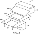
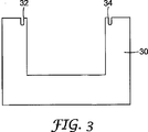
ここで図2を参照すると、ダイ12の分解斜視図が示されている。この図では、第1のダイ部分26、第2のダイ部分28、およびシム30のそれぞれが、ダイ12を組み立てた場合に位置が揃う1組の切り込み26N、28N、および30Nをそれぞれ有することがよく分かる。これらの切り込み26N、28N、および30Nを合わせたものが、アプリケータースロット24の側方の縁端部32、34を画定し、低キャピラリー数状況での作業中にコーティング22(図1)の側方への広がりを防止する。典型的には、低キャピラリー数状況は、キャピラリー数が約0.1未満となるときに存在するが、前述したようにより低いキャピラリー数の流れの状況ではキャピラリー数約0.5までの範囲となりうる。
Referring now to FIG. 2, an exploded perspective view of the die 12 is shown. In this figure, each of the
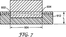
前述したように、本開示は、コーティングビードの縁端部に固定位置を提供することによってコーティングビードの広がりを防止することに関する。ある実施態様においては、この固定位置は、見かけのコーナーで最小曲率半径を有する幾何学的段差などの構造とされうる。あるいは、ダイ構成材料の濡れ性の急速または段階的な変化などの材料の物理的性質を利用して、固定位置を形成することによって、コーティングビードの側方への広がりを防止することもできる。また、固定位置は、(図7に示されるように)ダウンウェブ方向のダイの濡れる部分の全長Lに及ぶべきである。 As described above, the present disclosure relates to preventing spreading of the coating bead by providing a fixed position at the edge of the coating bead. In some embodiments, the fixed position may be a structure such as a geometric step having a minimum radius of curvature at an apparent corner. Alternatively, the physical properties of the material, such as rapid or gradual changes in the wettability of the die component material, can be used to prevent lateral spreading of the coating bead by forming a fixed location. Also, the fixed position should extend over the entire length L of the wetted portion of the die in the downweb direction (as shown in FIG. 7).
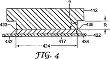
図4〜6を参照すると、ダイスロットの縁端部において固定位置を形成するための別の代表的な実施態様が示されている。図4を参照すると、代表的一実施態様のコーティングダイ412の断面が示されている。ダイ412は、コーティング材料417を供給するスロット424を含む。スロット424は、互いに反対側の第1の縁端部432および第2の縁端部434を含む。各縁端部432、434は、小さな半径を有するコーナー433、435を含む。この小さな半径は、固定位置として機能し、コーティング材料417が供給されるときにコーティング材料417をコーナーに固定し続け、それによってコーティングビードの側方への広がりが防止される。この小さな半径は、典型的には約0.050インチ(1.3ミリメートル)未満であり、理想的には約90°の角度θを形成する不連続部分である。しかし、この角度は、ダイが使用される個々の用途に依存して90°超であってもまたは90°未満であってもよい。また、ダイからコーティングされる材料の急増および脈動が、毛管現象のために、固定コーナー435の外側にはみ出すことがないようにするため、ダイ412の主要本体は、固定コーナー435から十分な距離Rだけくぼむべきである。個々のくぼみの距離Rはコーティング用途に依存するが、ほとんどの低キャピラリー数の流れでは、0.125インチ(3.18ミリメートル)で十分となる。
With reference to FIGS. 4-6, another exemplary embodiment for forming a fixed location at the edge of a die slot is shown. Referring to FIG. 4, a cross section of an exemplary embodiment coating die 412 is shown. The
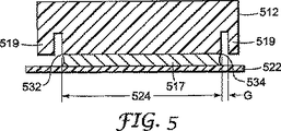
本開示のダイは、真空補助コーティングに使用することもできる。図5を参照すると、コーティングダイ512は、スロット524の各末端部532、534と近接した封止部材519も含むことができる。封止部材519によって、真空補助コーティング作業において図5に示されるダイ512が使用可能となる。ダイからコーティングされる材料の急増および脈動が、毛管現象のために、固定コーナー534と封止部材519との間をふさがないように、固定コーナー534と封止部材519との間の間隙Gが十分な距離となるべきである。個々の間隙距離Gはコーティング用途に依存するが、ほとんどの低キャピラリー数の流れでは、0.063インチ(1.60ミリメートル)で十分となる。
The die of the present disclosure can also be used for vacuum assisted coating. Referring to FIG. 5, the coating die 512 can also include a sealing
図6を参照すると、スロット824を有し、スロット824の各縁端部832、834において固定位置を有する代表的実施態様のコーティングダイ812が示されている。ダイ812およびコーティング材料817の物理的性質を使用することで固定が実現される。図示される代表的実施態様においては、ダイ812は、スロット824の縁端部832、834にインレイ(inlay)819を含む。インレイ819は、不十分に濡れるまたは濡れない材料で形成され、すなわちインレイに使用される材料は、ダイ本体に使用される材料よりも、コーティング材料との静的接触角が大きい。コーティング材料817が濡れない材料を使用すると、コーティング材料817がインレイ819に引っ張られるのが毛管力によって防止されることで固定位置が形成され、これによってコーティングビードの側方への広がりが防止される。不十分に濡れるまたは濡れない材料の例は、商品名テフロン(登録商標)(TEFLON(登録商標))で販売されるPTFE(ポリテトラフルオロエチレン)、および商品名デルリン(DELRIN)で販売されるアセタールポリオキシメチレンであり、どちらもデュポン(DuPont)より入手可能である。他の材料としては、フルオロポリマーなどの剥離ポリマーが挙げられる。フルオロポリマーの例は、テトラフルオロエチレン(TFE)、フッ化ビニル(VF)、パーフルオロアルキルビニルエーテル(PAVE)、2,2−ビストリフルオロメチル−4,5ジフルオロ−1,3−ジオキソール(PDD)、フッ化ビニリデン(VDF)、ヘキサフルオロプロピレン(HFP)などの基本モノマー、およびクロロトリフルオロエチレン(CTFE);ならびにフッ素化エチレンプロピレン(約18〜22ダイン/cmの表面エネルギー)、ポリフッ化ビニル(約28ダイン/cmの表面エネルギー)、ポリエチレンコポリマー(約20〜24ダイン/cmの表面エネルギー)、およびシリコーン(約24ダイン/cmの表面エネルギー)などのポリマーを含む。他の代表的な材料は、キストナー(Kistner)らに付与された米国特許第5,980,992号明細書、およびミルボーン(Milbourn)らに付与された米国特許第5,998,549号明細書に記載されており、これらを本明細書に援用する。
Referring to FIG. 6, an exemplary embodiment of a coating die 812 having a slot 824 and having a fixed position at each
あるいは、ダイ本体の濡れる領域に、金めっきなどの優先的に濡れる材料をコーティングすることができる。優先的に濡れる材料は、コーティングビードが固定位置から外れて側方に拡散および移動するのを防止する。別の代表的実施態様においては、水性のコーティング材料または溶液を使用する場合にダイの濡れる領域の縁端部に沿って疎水性テープを適用することができる。 Alternatively, a preferentially wettable material such as gold plating can be coated on the wetted area of the die body. The preferentially wetted material prevents the coating bead from escaping and moving laterally out of the fixed position. In another exemplary embodiment, a hydrophobic tape can be applied along the edge of the wetted area of the die when using an aqueous coating material or solution.
説明したそれぞれの代表的実施態様において、(図7に示されるように)固定位置が、機械方向でスロット924の長さ全体Lに及ぶことが好ましい。また、スロット924の両縁端部932、934は、典型的には同一の固定用配置を有するが、コーティングダイの使用の個々の条件の要求に応じて、記載される固定位置の種類のあらゆる組み合わせを使用することができる。
In each exemplary embodiment described, the fixed position (as shown in FIG. 7 ) preferably spans the entire length L of the
本発明の範囲および意図を逸脱しない本発明の種々の修正および変更は当業者に明らかとなるであろうし、本明細書に記載される説明的実施態様に本発明が限定されるものではないことを理解すべきである。 Various modifications and alterations of this invention will become apparent to those skilled in the art without departing from the scope and spirit of this invention and are not intended to limit the invention to the illustrative embodiments described herein. Should be understood.
Claims (13)
アプリケータースロットと流体連通しているキャビティを内部に有するダイ本体であって、第1のダイ部分、シム及び第2のダイ部分を有し、前記第1のダイ部分、前記シム及び前記第2のダイ部分が組み合わされて前記キャビティが形成されるというダイ本体と、
前記アプリケータースロットの少なくとも一端部における、供給される材料の側方への広がりを防止する手段とを具備し、
前記供給される材料の側方への広がりを防止する手段は、前記第1のダイ部分、前記シム及び前記第2のダイ部分内において前記アプリケータースロットの少なくとも一端部に隣接する切り込みと該切り込み内に配置されるインレイとである、コーティングダイ。A coating die for supplying material,
A die body having therein a cavity in fluid communication with an applicator slot, the die body having a first die portion, a shim and a second die portion, wherein the first die portion, the shim and the second die portion A die body in which the die portions are combined to form the cavity;
Means for preventing lateral spread of the supplied material at at least one end of the applicator slot;
The means for preventing lateral spreading of the supplied material includes a cut in the first die portion, the shim, and the second die portion adjacent to at least one end of the applicator slot and in the cut. The coating die , which is the inlay placed on .
請求項1から請求項8のいずれか一つの請求項に係るダイと、A die according to any one of claims 1 to 8,
供給される材料を受け取るために前記アプリケータースロットと隣接して配置された移動する基材とを具備し、A moving substrate disposed adjacent to the applicator slot to receive the material to be fed;
前記基材は、前記アプリケータースロットに対向するバックアップロール上で支持され、前記アプリケータースロットの少なくとも一端部における、供給される材料の側方への広がりを防止する手段は、キャピラリー数が約0.5までの範囲内のときに機能する、システム。The substrate is supported on a backup roll facing the applicator slot, and the means for preventing lateral spreading of the material to be supplied at least at one end of the applicator slot has a capillary number of about 0.5. A system that works when up to.
第1のダイ部分、シム及び第2のダイ部分を有し、前記第1のダイ部分、前記シム及び前記第2のダイ部分が組み合わされて、アプリケータースロットと流体連通しているキャビティを内部に有するダイ本体が形成されるというダイを提供するステップと、A cavity having a first die portion, a shim and a second die portion, wherein the first die portion, the shim and the second die portion are combined to be in fluid communication with the applicator slot. Providing a die that has a die body formed thereon;
移動する前記基材上に前記材料を供給するように前記アプリケータースロットが配置されるように前記ダイを方向付けるステップと、Orienting the die such that the applicator slot is positioned to deliver the material onto the moving substrate;
移動する前記基材上に前記材料が前記アプリケータースロットを介して供給されるように前記材料を前記キャビティ内に導入するステップであって、キャピラリー数が約0.5以下になるように前記材料は供給され、バックアップロールが前記アプリケータースロットに対向する前記基材を支持するステップと、Introducing the material into the cavity such that the material is fed through the applicator slot onto the moving substrate, wherein the material has a capillary number of about 0.5 or less. And a backup roll supports the substrate opposite the applicator slot;
供給される材料が前記アプリケータースロットの側方に広がるのを防止する防止手段であって、前記第1のダイ部分、前記シム及び前記第2のダイ部分内において前記アプリケータースロットの少なくとも一端部に隣接する切り込みと該切り込み内に配置されるインレイとである防止手段を、前記アプリケータースロットの少なくとも一端部上に配置するステップとを有する、方法。Preventing means for preventing material supplied from spreading laterally of the applicator slot, adjacent to at least one end of the applicator slot in the first die portion, the shim and the second die portion. Disposing a preventive means on the at least one end of the applicator slot.
Applications Claiming Priority (3)
| Application Number | Priority Date | Filing Date | Title |
|---|---|---|---|
| US10/760,794 | 2004-01-20 | ||
| US10/760,794 US7291362B2 (en) | 2004-01-20 | 2004-01-20 | Method and apparatus for controlling coating width |
| PCT/US2005/000573 WO2005070561A2 (en) | 2004-01-20 | 2005-01-07 | Method and apparatus for controlling coating width |
Publications (3)
| Publication Number | Publication Date |
|---|---|
| JP2007518558A JP2007518558A (en) | 2007-07-12 |
| JP2007518558A5 JP2007518558A5 (en) | 2008-02-28 |
| JP4773372B2 true JP4773372B2 (en) | 2011-09-14 |
Family
ID=34750074
Family Applications (1)
| Application Number | Title | Priority Date | Filing Date |
|---|---|---|---|
| JP2006551120A Expired - Fee Related JP4773372B2 (en) | 2004-01-20 | 2005-01-07 | Coating die, system for supplying material, and method of applying material to a moving substrate |
Country Status (7)
| Country | Link |
|---|---|
| US (2) | US7291362B2 (en) |
| EP (1) | EP1706215A2 (en) |
| JP (1) | JP4773372B2 (en) |
| KR (1) | KR101119764B1 (en) |
| CN (1) | CN100478084C (en) |
| BR (1) | BRPI0506891A (en) |
| WO (1) | WO2005070561A2 (en) |
Families Citing this family (12)
| Publication number | Priority date | Publication date | Assignee | Title |
|---|---|---|---|---|
| DE102006055112A1 (en) * | 2006-11-21 | 2008-05-29 | Billhöfer Maschinenfabrik GmbH & Co. KG | Apparatus for coating a welded or glued seam of a container, associated method and container produced by this method |
| US20100285227A1 (en) * | 2007-12-31 | 2010-11-11 | Yapel Robert A | Method for applying a coatable material |
| US8709315B2 (en) * | 2009-08-18 | 2014-04-29 | Exxonmobil Chemical Patents Inc. | Process for making thermoplastic polymer pellets |
| US8752501B2 (en) | 2010-07-29 | 2014-06-17 | Corning Incorporated | Systems and methods for dispensing a fluid |
| JP5315453B1 (en) * | 2012-03-07 | 2013-10-16 | 日東電工株式会社 | Shim member, die coater and coating film manufacturing method |
| US10627421B2 (en) * | 2012-03-16 | 2020-04-21 | Life Technologies Corporation | Coated substrate for biological reaction systems |
| US10000049B2 (en) * | 2014-06-23 | 2018-06-19 | Exel Industries | Methods and apparatus for applying protective films |
| EP3034182A1 (en) * | 2014-12-17 | 2016-06-22 | Nederlandse Organisatie voor toegepast- natuurwetenschappelijk onderzoek TNO | Coating system and coating method |
| WO2017139219A1 (en) * | 2016-02-12 | 2017-08-17 | 3M Innovative Properties Company | Slot die with actively controlled coating width |
| KR102248306B1 (en) * | 2017-07-13 | 2021-05-03 | 주식회사 엘지화학 | Coating Apparatus |
| CN108480138A (en) * | 2018-05-29 | 2018-09-04 | 安徽力信能源科技有限责任公司 | It is a kind of to be coated with uniform extrusion coating machine die head gasket and die head |
| US11839899B2 (en) * | 2020-02-12 | 2023-12-12 | Panasonic Holdings Corporation | Coating die and coating device |
Citations (7)
| Publication number | Priority date | Publication date | Assignee | Title |
|---|---|---|---|---|
| JPH06170306A (en) * | 1992-12-03 | 1994-06-21 | Konica Corp | Applicator |
| JP2514847B2 (en) * | 1989-09-01 | 1996-07-10 | 富士写真フイルム株式会社 | Coating device |
| JP2000511103A (en) * | 1996-05-31 | 2000-08-29 | ミネソタ・マイニング・アンド・マニュファクチャリング・カンパニー | Special contoured edge guide |
| JP2001170542A (en) * | 1999-12-20 | 2001-06-26 | Fuji Photo Film Co Ltd | Coating applicator |
| JP2002361150A (en) * | 2001-06-08 | 2002-12-17 | Fuji Photo Film Co Ltd | Spacer of coating apparatus, coating apparatus and production method of spacer |
| JP2003117474A (en) * | 2001-10-15 | 2003-04-22 | Sumitomo Chem Co Ltd | Method for forming thin film |
| JP2003200106A (en) * | 2001-10-29 | 2003-07-15 | Fuji Photo Film Co Ltd | Coating method |
Family Cites Families (21)
| Publication number | Priority date | Publication date | Assignee | Title |
|---|---|---|---|---|
| US4135477A (en) | 1975-09-22 | 1979-01-23 | Ciba-Geigy Ag | Curtain coating apparatus |
| US4299186A (en) * | 1977-01-17 | 1981-11-10 | International Business Machines Corporation | Method and apparatus for applying a viscous fluid to a substrate |
| JPS59150571A (en) * | 1983-02-18 | 1984-08-28 | Fuji Photo Film Co Ltd | Removal of extraneous matter adherent on surface of flexible supporting body |
| JPS61257268A (en) * | 1985-05-10 | 1986-11-14 | Fuji Photo Film Co Ltd | Coating method |
| JPS61257263A (en) * | 1985-05-10 | 1986-11-14 | Fuji Photo Film Co Ltd | Coating apparatus |
| US5114753A (en) * | 1988-12-21 | 1992-05-19 | Fuji Photo Film Co., Ltd. | Method and apparatus for coating web while preventing contact of edge portions thereof with coating head |
| US5435847A (en) * | 1989-09-01 | 1995-07-25 | Fuji Photo Film Co., Ltd. | Coating apparatus |
| US5067432A (en) | 1990-05-23 | 1991-11-26 | Extrusion Dies, Inc. | Replaceable wiping insert for slot die head |
| US5067423A (en) * | 1990-06-06 | 1991-11-26 | Thompson Elmer R | Sewing machine drive assembly, including pulley belt traction enhancement device |
| US5198030A (en) | 1991-06-18 | 1993-03-30 | E. I. Du Pont De Nemours And Company | Bead edge guide for use in slide-bead coating |
| JPH05169000A (en) * | 1991-12-17 | 1993-07-02 | Konica Corp | Coating method, coating device and coating die |
| US5389150A (en) | 1993-03-26 | 1995-02-14 | Eastman Kodak Company | Coating hopper inserts |
| US5759274A (en) | 1994-04-29 | 1998-06-02 | Minnesota Mining And Manufacturing Company | Die coating apparatus with surface covering |
| JP3282062B2 (en) * | 1994-12-16 | 2002-05-13 | コニカ株式会社 | Application method |
| US5998549A (en) | 1996-05-31 | 1999-12-07 | 3M Innovative Properties Company | Durable, low surface energy compounds and articles, apparatuses, and methods for using the same |
| DE29613687U1 (en) * | 1996-08-07 | 1996-10-24 | Voith Sulzer Papiermasch Gmbh | Applicator for direct or indirect application of a liquid or pasty coating medium to a running material web, in particular made of paper or cardboard |
| DE19649559A1 (en) * | 1996-11-29 | 1998-06-04 | Voith Sulzer Papiermasch Gmbh | Device for the direct or indirect application of a liquid or pasty coating medium to a running material web |
| US5980992A (en) | 1997-10-03 | 1999-11-09 | 3M Innovative Properties Company | Fluorochemical treatments to provide low-energy surfaces |
| US6319316B1 (en) | 1998-02-17 | 2001-11-20 | Fastar, Ltd. | System and method for performing low contamination extrusion for microelectronics applications |
| US6344088B1 (en) * | 1998-12-16 | 2002-02-05 | Matsushita Electric Industrial Co., Ltd. | Stripe coating applicator and method |
| US6766817B2 (en) | 2001-07-25 | 2004-07-27 | Tubarc Technologies, Llc | Fluid conduction utilizing a reversible unsaturated siphon with tubarc porosity action |
-
2004
- 2004-01-20 US US10/760,794 patent/US7291362B2/en not_active Expired - Fee Related
-
2005
- 2005-01-07 EP EP05711313A patent/EP1706215A2/en not_active Withdrawn
- 2005-01-07 CN CNB2005800028114A patent/CN100478084C/en not_active Expired - Fee Related
- 2005-01-07 KR KR1020067014450A patent/KR101119764B1/en not_active IP Right Cessation
- 2005-01-07 JP JP2006551120A patent/JP4773372B2/en not_active Expired - Fee Related
- 2005-01-07 WO PCT/US2005/000573 patent/WO2005070561A2/en active Application Filing
- 2005-01-07 BR BRPI0506891-6A patent/BRPI0506891A/en active Search and Examination
-
2007
- 2007-10-01 US US11/865,349 patent/US7625449B2/en not_active Expired - Fee Related
Patent Citations (7)
| Publication number | Priority date | Publication date | Assignee | Title |
|---|---|---|---|---|
| JP2514847B2 (en) * | 1989-09-01 | 1996-07-10 | 富士写真フイルム株式会社 | Coating device |
| JPH06170306A (en) * | 1992-12-03 | 1994-06-21 | Konica Corp | Applicator |
| JP2000511103A (en) * | 1996-05-31 | 2000-08-29 | ミネソタ・マイニング・アンド・マニュファクチャリング・カンパニー | Special contoured edge guide |
| JP2001170542A (en) * | 1999-12-20 | 2001-06-26 | Fuji Photo Film Co Ltd | Coating applicator |
| JP2002361150A (en) * | 2001-06-08 | 2002-12-17 | Fuji Photo Film Co Ltd | Spacer of coating apparatus, coating apparatus and production method of spacer |
| JP2003117474A (en) * | 2001-10-15 | 2003-04-22 | Sumitomo Chem Co Ltd | Method for forming thin film |
| JP2003200106A (en) * | 2001-10-29 | 2003-07-15 | Fuji Photo Film Co Ltd | Coating method |
Also Published As
| Publication number | Publication date |
|---|---|
| CN100478084C (en) | 2009-04-15 |
| WO2005070561A3 (en) | 2005-09-15 |
| US7291362B2 (en) | 2007-11-06 |
| KR101119764B1 (en) | 2012-03-23 |
| EP1706215A2 (en) | 2006-10-04 |
| US20050155549A1 (en) | 2005-07-21 |
| JP2007518558A (en) | 2007-07-12 |
| US7625449B2 (en) | 2009-12-01 |
| KR20070017110A (en) | 2007-02-08 |
| BRPI0506891A (en) | 2007-06-12 |
| WO2005070561A2 (en) | 2005-08-04 |
| CN1909974A (en) | 2007-02-07 |
| US20080022930A1 (en) | 2008-01-31 |
Similar Documents
| Publication | Publication Date | Title |
|---|---|---|
| JP4773372B2 (en) | Coating die, system for supplying material, and method of applying material to a moving substrate | |
| US9687872B2 (en) | Systems and methods for dispensing a fluid | |
| JPH0677711B2 (en) | Coating device | |
| JPH06190324A (en) | Coating apparatus | |
| JP3918106B2 (en) | Coating device | |
| JP2003080148A (en) | Coating apparatus | |
| JP2514847B2 (en) | Coating device | |
| MXPA06007976A (en) | Method and apparatus for controlling coating width | |
| KR100867908B1 (en) | A coating apparatus | |
| JP4264789B2 (en) | Application method and apparatus | |
| US5976251A (en) | Inlet for introducing water to wire edge guides for curtain coating | |
| JP4632643B2 (en) | Curtain coating method and apparatus for moving sheet | |
| JP2006281196A (en) | Application apparatus, application method and method for manufacturing web having coating film | |
| JP6960111B2 (en) | Coating equipment | |
| JP3193825B2 (en) | Coating device with blade | |
| JP6788681B2 (en) | Coating device and coating method | |
| JP3910268B2 (en) | Die type coating device | |
| JPH10277465A (en) | Coating method and coating device | |
| JPH04354562A (en) | Coating method | |
| JP2003088790A (en) | Coater | |
| JPH11139962A (en) | Coating of plaster and apparatus for coating plaster | |
| JP3448955B2 (en) | Coating device | |
| JPS6320070A (en) | Coater | |
| JPH08192087A (en) | Coating device | |
| JP2004216323A (en) | Coating device and coating method |
Legal Events
| Date | Code | Title | Description |
|---|---|---|---|
| A521 | Written amendment |
Free format text: JAPANESE INTERMEDIATE CODE: A523 Effective date: 20080107 |
|
| A621 | Written request for application examination |
Free format text: JAPANESE INTERMEDIATE CODE: A621 Effective date: 20080107 |
|
| A977 | Report on retrieval |
Free format text: JAPANESE INTERMEDIATE CODE: A971007 Effective date: 20100426 |
|
| A131 | Notification of reasons for refusal |
Free format text: JAPANESE INTERMEDIATE CODE: A131 Effective date: 20100511 |
|
| A521 | Written amendment |
Free format text: JAPANESE INTERMEDIATE CODE: A523 Effective date: 20100811 |
|
| A131 | Notification of reasons for refusal |
Free format text: JAPANESE INTERMEDIATE CODE: A131 Effective date: 20110125 |
|
| A521 | Written amendment |
Free format text: JAPANESE INTERMEDIATE CODE: A523 Effective date: 20110422 |
|
| TRDD | Decision of grant or rejection written | ||
| A01 | Written decision to grant a patent or to grant a registration (utility model) |
Free format text: JAPANESE INTERMEDIATE CODE: A01 Effective date: 20110524 |
|
| A61 | First payment of annual fees (during grant procedure) |
Free format text: JAPANESE INTERMEDIATE CODE: A61 Effective date: 20110623 |
|
| FPAY | Renewal fee payment (event date is renewal date of database) |
Free format text: PAYMENT UNTIL: 20140701 Year of fee payment: 3 |
|
| R150 | Certificate of patent or registration of utility model |
Ref document number: 4773372 Country of ref document: JP Free format text: JAPANESE INTERMEDIATE CODE: R150 Free format text: JAPANESE INTERMEDIATE CODE: R150 |
|
| R250 | Receipt of annual fees |
Free format text: JAPANESE INTERMEDIATE CODE: R250 |
|
| R250 | Receipt of annual fees |
Free format text: JAPANESE INTERMEDIATE CODE: R250 |
|
| R250 | Receipt of annual fees |
Free format text: JAPANESE INTERMEDIATE CODE: R250 |
|
| R250 | Receipt of annual fees |
Free format text: JAPANESE INTERMEDIATE CODE: R250 |
|
| R250 | Receipt of annual fees |
Free format text: JAPANESE INTERMEDIATE CODE: R250 |
|
| LAPS | Cancellation because of no payment of annual fees |