JP4773103B2 - Image forming apparatus and power-off method - Google Patents
Image forming apparatus and power-off method Download PDFInfo
- Publication number
- JP4773103B2 JP4773103B2 JP2005017526A JP2005017526A JP4773103B2 JP 4773103 B2 JP4773103 B2 JP 4773103B2 JP 2005017526 A JP2005017526 A JP 2005017526A JP 2005017526 A JP2005017526 A JP 2005017526A JP 4773103 B2 JP4773103 B2 JP 4773103B2
- Authority
- JP
- Japan
- Prior art keywords
- power supply
- door
- motor
- state
- power
- Prior art date
- Legal status (The legal status is an assumption and is not a legal conclusion. Google has not performed a legal analysis and makes no representation as to the accuracy of the status listed.)
- Expired - Fee Related
Links
Images


Landscapes
- Control Or Security For Electrophotography (AREA)
- Facsimiles In General (AREA)
- Accessory Devices And Overall Control Thereof (AREA)
Description
本発明は、電子写真式複写機、プリンタ装置、ファクシミリ装置、あるいは複写機能、プリンタ機能、ファクシミリ機能等の画像形成機能を具備した複合機等、モータの駆動により画像形成を行う画像形成装置に関し、特に筐体のドアが開状態になった場合においてモータを制御するモータドライバの破損防止技術を搭載した画像形成装置および電源遮断方法に関する。 The present invention relates to an image forming apparatus that forms an image by driving a motor, such as an electrophotographic copying machine, a printer apparatus, a facsimile apparatus, or a multifunction machine having an image forming function such as a copying function, a printer function, and a facsimile function. More particularly, the present invention relates to an image forming apparatus equipped with a motor driver breakage prevention technique for controlling a motor when a housing door is in an open state, and a power shutoff method.
従来の複写機等の画像形成装置では、画像形成装置に使用される複数の駆動用モータ及び電気回路基板に搭載される駆動用モータを制御するモータドライバ(モータ制御手段)を備えている(例えば、特許文献1参照)。このようなモータドライバに供給される電源は安全規格上、使用者が筐体のドアを開状態にすることより遮断される構造をなっている。このような画像形成装置では、通常その筐体に複数のドアが設けられており、各ドアごとに遮断される電源を複数有している。 A conventional image forming apparatus such as a copying machine includes a plurality of driving motors used in the image forming apparatus and a motor driver (motor control means) for controlling the driving motors mounted on the electric circuit board (for example, , See Patent Document 1). According to safety standards, the power supplied to such a motor driver has a structure that is shut off when the user opens the door of the housing. In such an image forming apparatus, a plurality of doors are usually provided in the casing, and a plurality of power supplies are shut off for each door.
しかしながら、このような従来技術には次のような問題がある。駆動用モータの回転中に利用者によって筐体のドアが開けられるとにより、電源が遮断され逆起電力が発生する。この逆起電力が発生する電源ラインにモータを制御するモータドライバの電源端子が接続されている場合、逆起電力によりモータドライバの耐圧を超えた電圧がかかると、モータドライバが破損してしまうという問題がある。 However, such a conventional technique has the following problems. When the user opens the housing door while the drive motor is rotating, the power is cut off and a back electromotive force is generated. If the power supply terminal of the motor driver that controls the motor is connected to the power supply line where the back electromotive force is generated, the motor driver will be damaged if a voltage exceeding the withstand voltage of the motor driver is applied due to the back electromotive force. There's a problem.
このようなドライバ破損を防止するために、電源ラインにはコンデンサを接続し、モータドライバの耐圧を超えた電流を吸収するが、電気回路基板の構造上の制約により、コンデンサを接続できない場合もある。 In order to prevent such damage to the driver, a capacitor is connected to the power supply line to absorb the current exceeding the withstand voltage of the motor driver. However, the capacitor may not be connected due to structural limitations of the electric circuit board. .
このような問題を解決するために、ドアの開状態によっても遮断されない独立した電源をモータドライバの電源に供給したり、モータの電源と異なる電源(5V系電源)をモータドライバ用の電源として使用するとともに、このような5V系電源でも動作するモータドライバを選定して使用していたが、選定するモータドライバに制限があるとともに、電気回路基板の構造が複雑になるという問題があった。 In order to solve such problems, an independent power source that is not shut off even when the door is open is supplied to the motor driver power source, or a power source different from the motor power source (5V system power source) is used as the motor driver power source. At the same time, a motor driver that operates even with such a 5V power supply is selected and used. However, there are problems that the motor driver to be selected is limited and the structure of the electric circuit board is complicated.
本発明は、上記に鑑みてなされたものであって、モータ制御手段を制限せずに使用することができ、回路構成を複雑化せずに、筐体のドアを開けた場合にモータ用のモータ制御手段の破損を防止することができる画像形成装置および電源監視方法を提供することを目的とする。 The present invention has been made in view of the above, and can be used without limiting the motor control means. When the housing door is opened without complicating the circuit configuration, the present invention is provided. An object of the present invention is to provide an image forming apparatus and a power supply monitoring method capable of preventing the motor control unit from being damaged.
上述した課題を解決し、目的を達成するために、請求項1にかかる発明は、モータの駆動により画像形成を行う画像形成装置であって、前記モータへの電流の供給のON/OFFを切り替える電界効果トランジスタを有し、前記モータを制御するモータ制御手段と、筐体のドアが閉状態から開状態に変化した場合に、前記モータ制御手段への電力供給を遮断する電源と、前記モータの電源であって、ドアが閉状態から開状態に変化した場合に一定期間の経過後に遮断される第2電源と、前記ドアの開閉を検知することにより前記電源の状態を検知する電源監視手段と、前記電源監視手段からの入力を監視して、前記電源が遮断されたことを検知した旨の入力があった場合に、前記第2電源の遮断前の前記一定期間内に、前記電界効果トランジスタをOFF状態に切り替えるドライバ制御信号を前記モータ制御手段に送出する制御手段と、を備えたことを特徴とする。 To solve the above problems and achieve the object, the invention according to claim 1 is an image forming apparatus for forming an image by driving the motor, the ON / OFF of the supply of current to the previous SL motor A motor control means for controlling the motor , a power supply for shutting off power supply to the motor control means when the housing door changes from a closed state to an open state; A second power source that shuts off after a lapse of a certain period of time when the door changes from a closed state to an open state, and a power source monitor that detects the state of the power source by detecting opening and closing of the door And when the input from the power supply monitoring means is detected to detect that the power supply has been cut off, the electric field is applied within the predetermined period before the second power supply is cut off. Effect transition And control means for sending a driver control signal for switching the data to the OFF state to the motor control means, characterized by comprising a.
また、請求項2にかかる発明は、請求項1に記載の画像形成装置において、前記制御手段は、予め定められた一定時間間隔で前記電源監視手段からの入力を監視することを特徴とする。 According to a second aspect of the present invention, in the image forming apparatus according to the first aspect, the control unit monitors an input from the power source monitoring unit at a predetermined time interval.
また、請求項3にかかる発明は、請求項1に記載の画像形成装置において、前記制御手段は、割り込みによって常時、前記電源監視手段からの入力を監視することを特徴とする。 According to a third aspect of the present invention, in the image forming apparatus according to the first aspect, the control unit constantly monitors an input from the power supply monitoring unit by interruption.
また、請求項4にかかる発明は、請求項1〜3のいずれか一つに記載の画像形成装置において、前記制御手段は、さらに、前記電源監視手段から前記電源が遮断されたことを検知した旨の入力があった後に、前記電源が接続されたことを検知した旨の入力を検知した場合に、前記電界効果トランジスタをON状態に切り替えるドライバ制御信号を前記モータ制御手段に送出することを特徴とする。 According to a fourth aspect of the present invention, in the image forming apparatus according to any one of the first to third aspects, the control unit further detects that the power source is shut off from the power source monitoring unit. A driver control signal for switching the field effect transistor to an ON state is sent to the motor control means when an input indicating that the power supply is detected is detected And
また、請求項5にかかる発明は、請求項1〜4のいずれか一つに記載の画像形成装置において、前記ドアの開閉状態の切り替えに伴って開閉する前記電源への電力供給の接続と遮断を切り替える開閉動作を行うドアスイッチをさらに備え、前記電源監視手段は、前記ドアスイッチの開閉状態により前記電源の状態を検知することを特徴とする。 According to a fifth aspect of the present invention, in the image forming apparatus according to any one of the first to fourth aspects, connection and interruption of power supply to the power source that opens and closes when the door is opened and closed is switched. And a door switch for performing an opening / closing operation for switching the power supply, wherein the power supply monitoring unit detects the state of the power supply based on the opening / closing state of the door switch.
また、請求項6にかかる発明は、請求項1〜5のいずれか一つに記載の画像形成装置において、前記電源と前記第2電源とが同一であることを特徴とする。 According to a sixth aspect of the present invention, in the image forming apparatus according to any one of the first to fifth aspects, the power source and the second power source are the same .
また、請求項7にかかる発明は、モータと、モータへの電流の供給のON/OFFを切り替える電界効果トランジスタを有し、前記モータを制御するモータ制御手段と、筐体のドアが閉状態から開状態に変化した場合に、前記モータ制御手段への電力供給を遮断する電源と、前記モータの電源であって、ドアが閉状態から開状態に変化した場合に一定期間の経過後に遮断される第2電源とを備え、前記モータの駆動により画像形成を行う画像形成装置における電源遮断方法であって、筐体のドアが閉状態から開状態に変化した場合に電力供給を遮断する電源の状態を、前記ドアの開閉を検知することにより検知する電源監視ステップと、前記電源監視ステップからの入力を監視して、前記電源が遮断されたことを検知した旨の入力があった場合に、前記第2電源の遮断前の前記一定期間内に、前記電界効果トランジスタをOFF状態に切り替えるドライバ制御信号を前記モータ制御手段に送出する制御ステップと、を含むことを特徴とする。 According to a seventh aspect of the present invention, there is provided a motor and a field effect transistor for switching ON / OFF of current supply to the motor, the motor control means for controlling the motor, and the housing door from the closed state. when changed to the open state, the power supply to cut off the power supply to the motor control unit, a power supply of the motor, the door is blocked after a certain period of time when changing from a closed state to an open state A power supply shutoff method in an image forming apparatus for forming an image by driving the motor, wherein the power supply shuts off the power supply when the housing door changes from a closed state to an open state. A power monitoring step for detecting the state by detecting the opening and closing of the door, and an input indicating that the power supply has been shut off by monitoring the input from the power monitoring step. To, in the predetermined period before interruption of said second power source, characterized in that it comprises a control step of transmitting a driver control signal for switching the field effect transistor in the OFF state to the motor control means.
請求項1にかかる発明によれば、電源が遮断されたことを検知した旨の入力があった場合に、前記電界効果トランジスタをOFF状態に切り替えるドライバ制御信号を前記モータ制御手段に送出することで、モータ制御手段を制限せずに使用することができ、回路構成を複雑化せずに、筐体のドアを開けた場合にモータ用のモータ制御手段の破損を防止することができるという効果を奏する。
また、請求項1にかかる発明によれば、より確実にモータ制御手段の破損を防止することができるという効果を奏する。
According to the first aspect of the present invention, when an input indicating that the power supply is detected is received, a driver control signal for switching the field effect transistor to the OFF state is sent to the motor control means. The motor control means can be used without restriction, and the motor control means for the motor can be prevented from being damaged when the housing door is opened without complicating the circuit configuration. Play.
Moreover, according to the invention concerning Claim 1, there exists an effect that damage to a motor control means can be prevented more reliably.
また、請求項2にかかる発明によれば、 前記制御手段は、予め定められた一定時間間隔で前記電源監視手段からの入力を監視することにより、画像形成装置に監視負担を比較的軽減させながらモータ制御手段の破損を防止することができるという効果を奏する。 According to a second aspect of the present invention, the control unit monitors an input from the power supply monitoring unit at a predetermined time interval, while relatively reducing the monitoring burden on the image forming apparatus. There is an effect that the motor control means can be prevented from being damaged.
また、請求項3にかかる発明によれば、割り込みによって常時、前記電源監視手段からの入力を監視することで、常時、モータ制御手段の破損を防止することができるという効果を奏する。 According to the invention of claim 3, by constantly monitoring the input from the power supply monitoring means by interruption, the motor control means can be prevented from being damaged at all times.
また、請求項4にかかる発明によれば、電源監視手段から前記電源が遮断されたことを検知した旨の入力があった後に、前記電源が接続されたことを検知した旨の入力を検知した場合に、前記電界効果トランジスタをON状態に切り替えるドライバ制御信号を前記モータ制御手段に送出することで、使用者がドアを開けた後に閉めた場合にモータの回転を再開させて画像形成動作を正常に実行させることができるという効果を奏する。 According to the invention according to claim 4, after an input indicating that the power supply is detected from the power supply monitoring means, an input indicating that the power supply is detected is detected. In this case, by sending a driver control signal for switching the field effect transistor to the ON state to the motor control means, when the user closes the door after opening the door, the rotation of the motor is resumed and the image forming operation is normally performed. There is an effect that can be executed.
また、請求項5にかかる発明によれば、ドアスイッチの開閉状態により前記電源の状態を検知することで、回路構成を複雑化せずに、筐体のドアを開けた場合にモータ用のモータ制御手段の破損を防止することができるという効果を奏する。 According to the invention according to claim 5, when the door of the housing is opened without complicating the circuit configuration by detecting the state of the power supply based on the open / closed state of the door switch, the motor for the motor is used. The control means can be prevented from being damaged.
また、請求項6にかかる発明によれば、電源と第2電源とが同一であるので、電源が遮断されると直ちにモータ制御手段への電流供給が遮断され、より確実にモータ制御手段の破損を防止することができるという効果を奏する。 According to the invention of claim 6, since the power source and the second power source are the same, the current supply to the motor control means is immediately shut off when the power source is shut off, and the motor control means is more reliably damaged. There is an effect that can be prevented.
また、請求項7にかかる発明によれば、電源が遮断されたことを検知した旨の入力があった場合に、前記電界効果トランジスタをOFF状態に切り替えるドライバ制御信号を前記モータ制御手段に送出することで、モータ制御手段を制限せずに使用することができ、回路構成を複雑化せずに、筐体のドアを開けた場合にモータ用のモータ制御手段の破損を防止することができるという効果を奏する。
また、請求項7にかかる発明によれば、より確実にモータ制御手段の破損を防止することができるという効果を奏する。
According to the seventh aspect of the present invention, when there is an input indicating that the power supply has been cut off, a driver control signal for switching the field effect transistor to the OFF state is sent to the motor control means. Thus, the motor control means can be used without restriction, and the motor control means for the motor can be prevented from being damaged when the housing door is opened without complicating the circuit configuration. There is an effect.
Moreover, according to the invention concerning Claim 7, there exists an effect that damage to a motor control means can be prevented more reliably.
以下に添付図面を参照して、この発明にかかる画像形成装置および電源遮断方法の最良な実施の形態を詳細に説明する。 Exemplary embodiments of an image forming apparatus and a power shut-off method according to the present invention are explained in detail below with reference to the accompanying drawings.
(実施の形態1)
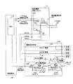
図1は、実施の形態1にかかる画像形成装置の電気系統の構成を示す回路図である。また、図2は、実施の形態1にかかる画像形成装置の筐体の外観を示す模式図である。
(Embodiment 1)
FIG. 1 is a circuit diagram illustrating a configuration of an electrical system of the image forming apparatus according to the first embodiment. FIG. 2 is a schematic diagram illustrating an appearance of a housing of the image forming apparatus according to the first embodiment.
実施の形態1にかかる画像形成装置は、図1に示すように、そのコントローラ部に制御基板120と、直流電源供給ユニット119と、電気回路基板118とを搭載した電気系統を有している。
As shown in FIG. 1, the image forming apparatus according to the first embodiment has an electrical system in which a
電気回路基板118には、24VS1電源107、24VS2電源108と、24VS3電源109と、モータ111a,111bと、ドライバ110a,110bと、大容量コンデンサ112が搭載されている。
On the
24VS1電源107はドアSW1に接続されている。24VS2電源108は、モータ111bとドライバ110bとドアSW2に接続されている。24VS3電源109は、モータ111aとドライバ110aとリレー105に接続されている。すなわち、24VS3電源109は、モータ111aとドライバ110aの両方に電源を供給している。
The
ドライバ110bは、モータ111bの駆動を制御する回路である。ドライバ110aは、モータ111aの駆動を制御する回路であり、その内部にFET(電界効果トランジスタ)112を備えている。すなわち、FET112がON状態のときには電流を通電してモータ111aの駆動状態を維持し、FET112がOFF状態に切り替わると電流を遮断してモータ111aを停止するように制御する。このFET112は、上述したCPU114から起動信号を入力するとOFF状態からON状態に切り替わり、上述したCPU114から停止信号を入力するとON状態からOFF状態に切り替わって電流を遮断する。ここで、ドライバ110aは本発明におけるモータ制御手段に相当する。直流電源供給ユニット119は直流電源を供給するものである。直流電源供給ユニット119には、筐体の前ドア201の開閉に従って開閉するドアSW1と、縦搬送ドア202の開閉に応じて開閉するドアSW2と、リレー105と、電源監視回路106が設けられている。
The
ドアSW1は、後述する電気回路基板118の24VS1電源107に接続されており、前ドア201が閉状態の時は閉状態となって24VS1電源107を接した状態となっている。しかし、前ドア201が利用者によって開けられると、ドアSW1は開放状態となり、24VS1電源107を遮断するようになっている。
The door SW1 is connected to a
ドアSW2は、ドアSW1と電気回路基板118の24VS2電源108に接続されており、縦搬送ドア202が閉状態の時は閉状態となって24VS2電源108を接した状態となっている。しかし、縦搬送ドア202が利用者によって開けられると、ドアSW2は開放状態となり、24VS2電源108を遮断するようになっている。
The door SW2 is connected to the door SW1 and the 24VS2 power source 108 of the
リレー105は、電気回路基板118の24VS3電源109に接続されており、供給される電源電圧が一定値以下になると開放状態となる。
The
本実施の形態では、前ドア201が開状態となると、ドアSW1が開放状態となるので、24VS1電源107が遮断され、ドアSW1に接続されたドアSW2も開放状態となり、24VS2電源108も遮断される。また、このとき、リレー105に供給される電源電圧が一定時間経過後に一定値以下となり開放状態となるので、24VS3電源も遮断されることになる。
In this embodiment, when the
一方、縦搬送ドア202が開状態となると、ドアSW1は24VS1電源は遮断されないが、24VS2電源108が遮断され、リレー105に供給される電源電圧が一定時間経過後に一定値以下となり開放状態となるので、24VS3電源も遮断されることになる。このように、ドアSW1、SW2を設けることにより、遮断される電源と遮断されない電源が存在することになる。
On the other hand, when the
電源監視回路106は、ドアSW1が開放状態の場合(すなわち、前ドア201が開状態になったことを検知すると)にドアSW1開検知信号をCPU114に送出し、ドアSW2が開放状態の場合(すなわち、縦搬送ドア202が開状態になったことを検知すると)にドアSW2開検知信号をCPU114に送出する回路である。
The
また、電源監視回路106は、ドアSW1が閉状態の場合にドアSW1開検知信号をCPU114に送出せず、ドアSW2が閉状態の場合にドアSW2開検知信号をCPU114に送出しないようになっている。
The
制御基板120には主としてCPU114が搭載されている。CPU114は、制御基板120の入力端子の状態を監視し、各入力端子からドアSW1開検知信号、ドアSW2開検知信号が入力されて否かにより、24VS1電源107と24VS2電源108の電源状態(遮断されたか否か)を監視する。CPU114は、ドアSW1開検知信号が入力されている場合には、24VS1電源107が遮断していると判断し、ドアSW1開検知信号の入力が停止している場合には、24VS1電源107が接続されていると判断する。また、CPU114は、ドアSW2開検知信号が入力されている場合には、24VS2電源108が遮断していると判断し、ドアSW2開検知信号の入力が停止している場合には、24VS2電源108が接続されていると判断する。
A
また、CPU114は、直流電源ユニット119の電源監視回路106からドアSW1開検知信号とドアSW2開検知信号を各入力端子から入力した場合に、電気回路基板118のドライバ110aに停止信号のドライバ制御信号を送出する。また、CPU114は、直流電源ユニット119の電源監視回路106からドアSW1開検知信号およびドアSW2開検知信号の各入力端子からの入力が停止した場合に、電気回路基板118のドライバ110aに起動信号のドライバ制御信号を送出する。
In addition, when the
ここで、停止信号は、ドライバ110a内部のFET(電界効果トランジスタ)112をON状態からOFF状態に切り替える指令であり、起動信号は、FET112をOFF状態からON状態に切り替える指令である。CPU114は、本発明における制御手段に相当する。
Here, the stop signal is a command for switching the FET (field effect transistor) 112 in the
本実施の形態では、CPU114は、電源の状態を一定時間ごとに監視している。
In the present embodiment, the
ここで、上述のように、ドアSW1、SW2のいずれかが開放状態になると、リレー105によって一定時間経過後に24VS3電源が遮断されるので、結局、電源監視回路106は、モータ111およびドライバ110に接続された24VS3電源の電源の状態を監視していることになる。
Here, as described above, when either of the doors SW1 and SW2 is in an open state, the 24VS3 power supply is shut off after a lapse of a predetermined time by the
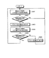
次に、以上のように構成された本実施の形態におけるドライバ110aの電源遮断方法について説明する。図3は、実施の形態におけるドライバ110aの電源遮断処理の手順を示すフローチャートである。
Next, a method for powering off the
まず、CPU114は、予め定められた一定時間ごとに入力端子からの入力信号を監視することによって、24VS1電源と24VS2電源の各状態を監視する(ステップS301)。具体的には、電源監視回路106からドアSW1開信号またはドアSW2開信号が入力されたか否かを一定時間ごとに監視して、24VS1電源107、24VS2電源108のいずれかが遮断状態になったか否か、すなわちドアが開状態となってドアSW1,SW2のいずれかが開放状態になったか否かを判断する(ステップS302)。そして、24VS1電源107、24VS2電源108のいずれも遮断状態になってない場合には(ステップS302:No)、前ドア201も縦搬送ドア202も開けられていないと判断して、一定時間後に電源状態の監視を行う。
First, the
一方、ステップS302において、24VS1電源107、24VS2電源108のいずれかが遮断状態になった場合(ドアSW1、SW2のいずれかが開放状態になった場合)には(ステップS302:No)、前ドア201、縦搬送ドア202のいずれかが開けられたと判断して、ドライバ110a内部のFET112をOFF状態にする(ステップS303)。具体的には、CPU114は、電源監視回路106から入力端子に入力されたドアスイッチ開検知信号(ドアSW1開検知信号またはドアSW2開検知信号)を受け取ると、ドライバ110aに対して停止信号を送出する。ドライバ110aは、停止信号を受け取ると、内部のFET112をOFF状態にする。これにより、ドライバ110a内部の電流は遮断され、モータ111aに電流が流れなくなる。
On the other hand, if any of the
すなわち、FET112がON状態でモータ111aが回転中に、使用者が前ドア201または縦搬送ドア202を開放されて、24VS1電源107また24VS2電源108が遮断されると、一定時間経過後にリレー105が開放され24VS3電源が遮断される。従来の画像形成装置では、このとき、モータ111aに電流が流れており回転中のため、24VS3電源109に逆起電力が発生し、ドライバ110aの電源端子131が24VS3電源109と接続されているので、逆起電力が電源端子131の定格値を超えてドライバ110aが破壊されてしまう。
That is, if the user opens the
しかしながら、本実施の形態では、使用者が各ドアを開状態としたことにより、ドアSW1、SW2のいずれかが開放された場合、電源監視回路106が各ドアに対応したドア開検知信号をCPU114に送出し、リレー105によって24VS3電源が遮断するまでの一定時間内に、FET112をOFF状態にしているので、モータ111aに電流が流れなくなる。その後24VS3電源109が遮断されるが、モータ111aに電流が流れていないため逆起電力が生じずドライバ破損を防ぐことができる。
However, in the present embodiment, when one of the doors SW1 and SW2 is opened by the user opening each door, the power
次いで、CPU114は、更に一定時間ごとに入力端子からの入力の状態を監視する(ステップS304)。具体的には、電源監視回路106からドアSW1開信号またはドアSW2開信号の入力が停止したか否かを一定時間ごとに監視する。そして、24VS1電源107、24VS2電源108のいずれかがまだ遮断状態であるか否か、すなわち前ドア201と縦搬送ドア202がいずれかがまだ開状態でありドアSW1,SW2のいずれかが開放状態であるか否か(いずれかの開検知信号が入力されているか否か)を判断する(ステップS305)。
Next, the
そして、24VS1電源107、24VS2電源108のいずれかが遮断状態である場合には(ステップS305:Yes)、CPU114は、前ドア201と縦搬送ドア202のいずれかがまだ開いていると判断して、さらに一定時間後に電源状態の監視を行う。
If either of the
一方、ステップS305において、24VS1電源107、24VS2電源108のいずれも接続状態になった場合(ドアSW1、SW2がいずれも接続状態になった場合)には(ステップS305:No)、前ドア201、縦搬送ドア202のいずれも閉められたと判断して、ドライバ110a内部のFET112をON状態にする(ステップS306)。具体的には、電源監視回路106からドアSW1開検知信号およびドアSW2開検知信号の両方がCPU114の入力端子への入力が停止した場合、CPU114は、ドライバ110aに対して起動信号を送出する。ドライバ110aは、起動信号を受け取ると、内部のFET112をON状態にする。これにより、ドライバ110a内部の電流が通電し、24VS3電源が接続状態となる。
On the other hand, if both the
このように本実施の形態にかかる画像形成装置では、使用者が各ドアを開状態としたことにより、ドアSW1、SW2のいずれかが開放された場合、電源監視回路106が各ドアに対応したドア開検知信号をCPU114に送出し、リレー105によって24VS3電源が遮断するまでの一定時間内に、FET112をOFF状態にしているので、モータ111aを制御するドライバを制限せずに選定して使用することができ、回路構成を複雑化せずに、筐体のドア201、202を開けた場合に逆起電力によるドライバの破損を防止することができる。
As described above, in the image forming apparatus according to the present embodiment, when one of the doors SW1 and SW2 is opened by the user opening each door, the
(実施の形態1の変形態様)
実施の形態1にかかる画像形成装置ではCPU114が一定時間ごとにドアSW1,SW2の状態を監視していたが、割り込みにより常時ドアSW1,SW2の状態を監視することにより、24VS1電源107、24VS2電源108、24VS3電源109の電源状態(遮断されたか否か)の状態を監視するように構成してもよい。図4は、常時監視の場合におけるドライバ110aの電源遮断処理の手順を示すフローチャートである。
(Modification of the first embodiment)
In the image forming apparatus according to the first embodiment, the
図4では、ステップS401およびステップS404において、割り込みにより常時ドアSW1,SW2の状態を監視する点が実施の形態1のドライバ110aの電源遮断処理(ステップS301およびステップS304)と異なっており、他の処理については実施の形態1と同様に行われる。
4 is different from the power-off process (steps S301 and S304) of the
(実施の形態2)
実施の形態1の画像形成装置では、ドライバ110aの電源端子に接続して電源を供給する24VS3電源509が、ドアSW1,SW2で遮断される24VS1電源107、24VS2電源108と異なるものであったが、この実施の形態2かかる画像形成装置は、ドライバの電源端子に接続して電源を供給する電源が、ドアSW2で遮断される電源となるように構成したものである。
(Embodiment 2)
In the image forming apparatus of the first embodiment, the 24VS3 power supply 509 that supplies power by connecting to the power supply terminal of the
図5は、実施の形態2にかかる画像形成装置の電気系統の構成を示す回路図である。実施の形態2にかかる画像形成装置は、図5に示すように、そのコントローラ部に制御基板120と、直流電源供給ユニット119と、電気回路基板518とを搭載した電気系統を有している。制御基板120と直流電源供給ユニット119については実施の形態1と同様の構成および機能を有している。
FIG. 5 is a circuit diagram illustrating a configuration of an electrical system of the image forming apparatus according to the second embodiment. As shown in FIG. 5, the image forming apparatus according to the second embodiment has an electrical system in which a
電気回路基板518には、24VS1電源507、24VS2電源508と、24VS3電源509と、モータ111a,111bと、ドライバ110a,110bと、大容量コンデンサ112が搭載されている。
On the electric circuit board 518, a
24VS1電源507はドアSW1に接続されている。24VS2電源508は、ドライバ510aと、ドライバ510bとドアSW2に接続されている。24VS3電源509は、モータ111aリレー105に接続されている。すなわち、24VS3電源509は、モータ111aに電源を供給しており、24VS2電源508は、モータ111aを制御するドライバ510aに電源を供給しており、モータ111aとそのドライバ510aの電源が異なっている。さらに、本実施形態では、ドライバ510aの電源端子に接続して電源を供給する24VS2電源508が、ドアSW2で遮断される電源となっている。
The
このように本実施の形態では、ドライバ510aの電源端子に接続して電源を供給する24VS2電源508が、ドアSW2で遮断される電源となるように構成しているので、使用者がドアを開けたことにより24VS1電源、24VS2電源が遮断された場合、ドライバ510aの電源でもある24VS2電源508が遮断されるので、FET112がOFF状態となる。従って、モータ111aの電源である24VS3電源が遮断される時には、モータ111aに電流が流れず逆起電力が発生せず、ドライバ510aの破損を防止することができる。
Thus, in this embodiment, the 24VS2 power supply 508 that supplies power by connecting to the power supply terminal of the
103 ドアSW1
104 ドアSW2
105 リレー
106 電源監視回路
107 24VS1電源
108 24VS2電源
109 24VS3電源
110a,110b、510a,510b ドライバ
111a,111b モータ
111 モータ
112 大容量コンデンサ
114 CPU
118,518 電気回路基板
119 直流電源供給ユニット
120 制御基板
131 電源端子
103 Door SW1
104 Door SW2
105
118,518
Claims (7)
前記モータへの電流の供給のON/OFFを切り替える電界効果トランジスタを有し、前記モータを制御するモータ制御手段と、
筐体のドアが閉状態から開状態に変化した場合に、前記モータ制御手段への電力供給を遮断する電源と、
前記モータの電源であって、ドアが閉状態から開状態に変化した場合に一定期間の経過後に遮断される第2電源と、
前記ドアの開閉を検知することにより前記電源の状態を検知する電源監視手段と、
前記電源監視手段からの入力を監視して、前記電源が遮断されたことを検知した旨の入力があった場合に、前記第2電源の遮断前の前記一定期間内に、前記電界効果トランジスタをOFF状態に切り替えるドライバ制御信号を前記モータ制御手段に送出する制御手段と、
を備えたことを特徴とする画像形成装置。 An image forming apparatus that forms an image by driving a motor ,
Has a field-effect transistor for switching ON / OFF of current supply to the front SL motor, and motor control means for controlling said motor,
A power source that cuts off the power supply to the motor control means when the door of the housing changes from a closed state to an open state;
The power supply of the motor, a second power source is cut off after a certain period if the door is changed from a closed state to an open state,
Power supply monitoring means for detecting the state of the power supply by detecting opening and closing of the door;
When the input from the power supply monitoring unit is monitored and it is detected that the power supply is cut off, the field effect transistor is turned on within the predetermined period before the second power supply is cut off. Control means for sending a driver control signal for switching to the OFF state to the motor control means;
An image forming apparatus comprising:
前記電源監視手段は、前記ドアスイッチの開閉状態により前記電源の状態を検知することを特徴とする請求項1〜4のいずれか一つに記載の画像形成装置。 A door switch for performing an opening / closing operation for switching between connection and interruption of power supply to the power source that opens and closes in accordance with switching of the opening / closing state of the door;
The image forming apparatus according to claim 1, wherein the power monitoring unit detects a state of the power source based on an open / close state of the door switch.
筐体のドアが閉状態から開状態に変化した場合に電力供給を遮断する電源の状態を、前記ドアの開閉を検知することにより検知する電源監視ステップと、
前記電源監視ステップからの入力を監視して、前記電源が遮断されたことを検知した旨の入力があった場合に、前記第2電源の遮断前の前記一定期間内に、前記電界効果トランジスタをOFF状態に切り替えるドライバ制御信号を前記モータ制御手段に送出する制御ステップと、
を含むことを特徴とする電源遮断方法。 A motor and a field-effect transistor that switches ON / OFF of current supply to the motor, the motor control means for controlling the motor, and the motor when the housing door changes from a closed state to an open state. a power source to cut off the power supply to the control unit, a power supply of said motor, and a second power source is cut off after a certain period if the door is changed from a closed state to an open state, the motor A power shut-off method in an image forming apparatus that forms an image by driving,
A power supply monitoring step for detecting the state of the power supply that cuts off the power supply when the door of the housing changes from the closed state to the open state by detecting the opening and closing of the door;
When the input from the power supply monitoring step is monitored and it is detected that the power supply is cut off, the field effect transistor is turned on within the predetermined period before the second power supply is cut off. A control step of sending a driver control signal for switching to the OFF state to the motor control means;
A power shut-off method comprising:
Priority Applications (1)
| Application Number | Priority Date | Filing Date | Title |
|---|---|---|---|
| JP2005017526A JP4773103B2 (en) | 2005-01-25 | 2005-01-25 | Image forming apparatus and power-off method |
Applications Claiming Priority (1)
| Application Number | Priority Date | Filing Date | Title |
|---|---|---|---|
| JP2005017526A JP4773103B2 (en) | 2005-01-25 | 2005-01-25 | Image forming apparatus and power-off method |
Publications (2)
| Publication Number | Publication Date |
|---|---|
| JP2006208502A JP2006208502A (en) | 2006-08-10 |
| JP4773103B2 true JP4773103B2 (en) | 2011-09-14 |
Family
ID=36965469
Family Applications (1)
| Application Number | Title | Priority Date | Filing Date |
|---|---|---|---|
| JP2005017526A Expired - Fee Related JP4773103B2 (en) | 2005-01-25 | 2005-01-25 | Image forming apparatus and power-off method |
Country Status (1)
| Country | Link |
|---|---|
| JP (1) | JP4773103B2 (en) |
Families Citing this family (4)
| Publication number | Priority date | Publication date | Assignee | Title |
|---|---|---|---|---|
| JP4890240B2 (en) * | 2006-12-28 | 2012-03-07 | 京セラミタ株式会社 | Electrical equipment |
| JP5538316B2 (en) * | 2011-07-25 | 2014-07-02 | 京セラドキュメントソリューションズ株式会社 | Sheet conveying apparatus, automatic document feeder, and image forming apparatus |
| JP5825274B2 (en) * | 2013-02-01 | 2015-12-02 | コニカミノルタ株式会社 | Image forming apparatus and control method thereof |
| JP6471324B2 (en) * | 2017-06-26 | 2019-02-20 | 株式会社サンセイアールアンドディ | Game machine |
Family Cites Families (3)
| Publication number | Priority date | Publication date | Assignee | Title |
|---|---|---|---|---|
| JP2862714B2 (en) * | 1991-09-27 | 1999-03-03 | シャープ株式会社 | Electronic equipment with motor |
| JP3293212B2 (en) * | 1993-01-26 | 2002-06-17 | ミノルタ株式会社 | Image forming device |
| WO2000021177A1 (en) * | 1998-10-06 | 2000-04-13 | Fujitsu Limited | Power supply circuit with function of preventing reverse flow noise |
-
2005
- 2005-01-25 JP JP2005017526A patent/JP4773103B2/en not_active Expired - Fee Related
Also Published As
| Publication number | Publication date |
|---|---|
| JP2006208502A (en) | 2006-08-10 |
Similar Documents
| Publication | Publication Date | Title |
|---|---|---|
| WO2005091488A8 (en) | Motor controller | |
| EP1134631B1 (en) | Submergence-detecting power-window apparatus | |
| JP4773103B2 (en) | Image forming apparatus and power-off method | |
| JP2006197766A (en) | Drive system and control method therefor | |
| JP2774907B2 (en) | Electric vehicle control device | |
| JP2009248885A (en) | Auxiliary power supply system of electric power steering device | |
| JP2008199707A (en) | Motor controller | |
| US9263207B2 (en) | Switch device | |
| JP3693226B2 (en) | Microcomputer backup device and automotive power window control device | |
| JP2007147677A (en) | Image forming apparatus | |
| JP3406925B2 (en) | Image forming apparatus and power supply control apparatus | |
| JP3998632B2 (en) | Electric vehicle control device | |
| JP5011778B2 (en) | Motor drive system and control method thereof | |
| JP3462048B2 (en) | Computer monitoring device and power window system | |
| JP4548241B2 (en) | Power supply | |
| JP4726665B2 (en) | Time switch for motor control | |
| JPS60187578A (en) | Printer | |
| JP2002214965A (en) | Image forming device | |
| JP2002061456A (en) | Motor door | |
| JP2005133968A (en) | Air-conditioner | |
| JP2007240019A (en) | Air conditioner | |
| JP4124140B2 (en) | Air conditioner | |
| JP2002159143A (en) | Power supply circuit and image forming apparatus having the circuit | |
| JP2006000973A (en) | Battery-type motor-driven tool | |
| JP2002129832A (en) | Power window device |
Legal Events
| Date | Code | Title | Description |
|---|---|---|---|
| A621 | Written request for application examination |
Free format text: JAPANESE INTERMEDIATE CODE: A621 Effective date: 20070622 |
|
| A977 | Report on retrieval |
Free format text: JAPANESE INTERMEDIATE CODE: A971007 Effective date: 20091228 |
|
| A131 | Notification of reasons for refusal |
Free format text: JAPANESE INTERMEDIATE CODE: A131 Effective date: 20100119 |
|
| A521 | Written amendment |
Free format text: JAPANESE INTERMEDIATE CODE: A523 Effective date: 20100323 |
|
| A131 | Notification of reasons for refusal |
Free format text: JAPANESE INTERMEDIATE CODE: A131 Effective date: 20100615 |
|
| A521 | Written amendment |
Free format text: JAPANESE INTERMEDIATE CODE: A523 Effective date: 20100816 |
|
| A131 | Notification of reasons for refusal |
Free format text: JAPANESE INTERMEDIATE CODE: A131 Effective date: 20101130 |
|
| A521 | Written amendment |
Free format text: JAPANESE INTERMEDIATE CODE: A523 Effective date: 20110131 |
|
| TRDD | Decision of grant or rejection written | ||
| A01 | Written decision to grant a patent or to grant a registration (utility model) |
Free format text: JAPANESE INTERMEDIATE CODE: A01 Effective date: 20110621 |
|
| A01 | Written decision to grant a patent or to grant a registration (utility model) |
Free format text: JAPANESE INTERMEDIATE CODE: A01 |
|
| A61 | First payment of annual fees (during grant procedure) |
Free format text: JAPANESE INTERMEDIATE CODE: A61 Effective date: 20110623 |
|
| FPAY | Renewal fee payment (event date is renewal date of database) |
Free format text: PAYMENT UNTIL: 20140701 Year of fee payment: 3 |
|
| R150 | Certificate of patent or registration of utility model |
Free format text: JAPANESE INTERMEDIATE CODE: R150 |
|
| LAPS | Cancellation because of no payment of annual fees |