JP4771663B2 - Configuration and method for improved acid gas removal - Google Patents
Configuration and method for improved acid gas removal Download PDFInfo
- Publication number
- JP4771663B2 JP4771663B2 JP2003585859A JP2003585859A JP4771663B2 JP 4771663 B2 JP4771663 B2 JP 4771663B2 JP 2003585859 A JP2003585859 A JP 2003585859A JP 2003585859 A JP2003585859 A JP 2003585859A JP 4771663 B2 JP4771663 B2 JP 4771663B2
- Authority
- JP
- Japan
- Prior art keywords
- solvent
- gas
- absorber
- plant
- carbon dioxide
- Prior art date
- Legal status (The legal status is an assumption and is not a legal conclusion. Google has not performed a legal analysis and makes no representation as to the accuracy of the status listed.)
- Expired - Fee Related
Links
- 238000000034 method Methods 0.000 title claims description 36
- 239000002253 acid Substances 0.000 title description 38
- 239000002904 solvent Substances 0.000 claims description 209
- 239000007789 gas Substances 0.000 claims description 187
- CURLTUGMZLYLDI-UHFFFAOYSA-N Carbon dioxide Chemical compound O=C=O CURLTUGMZLYLDI-UHFFFAOYSA-N 0.000 claims description 118
- 239000006096 absorbing agent Substances 0.000 claims description 89
- 239000001569 carbon dioxide Substances 0.000 claims description 59
- 229910002092 carbon dioxide Inorganic materials 0.000 claims description 59
- 239000004215 Carbon black (E152) Substances 0.000 claims description 36
- 229930195733 hydrocarbon Natural products 0.000 claims description 36
- 150000002430 hydrocarbons Chemical class 0.000 claims description 36
- VNWKTOKETHGBQD-UHFFFAOYSA-N methane Chemical compound C VNWKTOKETHGBQD-UHFFFAOYSA-N 0.000 claims description 30
- 238000001816 cooling Methods 0.000 claims description 21
- 239000003345 natural gas Substances 0.000 claims description 13
- 238000011084 recovery Methods 0.000 claims description 11
- 239000002737 fuel gas Substances 0.000 claims description 10
- RUOJZAUFBMNUDX-UHFFFAOYSA-N propylene carbonate Chemical compound CC1COC(=O)O1 RUOJZAUFBMNUDX-UHFFFAOYSA-N 0.000 claims description 9
- 230000018044 dehydration Effects 0.000 claims description 8
- 238000006297 dehydration reaction Methods 0.000 claims description 8
- 239000002826 coolant Substances 0.000 claims description 6
- 230000036571 hydration Effects 0.000 claims description 4
- 238000006703 hydration reaction Methods 0.000 claims description 4
- 230000001172 regenerating effect Effects 0.000 claims description 4
- 230000002745 absorbent Effects 0.000 claims 1
- 239000002250 absorbent Substances 0.000 claims 1
- 239000012530 fluid Substances 0.000 claims 1
- 239000000047 product Substances 0.000 description 18
- 238000010521 absorption reaction Methods 0.000 description 11
- 239000003921 oil Substances 0.000 description 10
- 239000012528 membrane Substances 0.000 description 9
- XLYOFNOQVPJJNP-UHFFFAOYSA-N water Substances O XLYOFNOQVPJJNP-UHFFFAOYSA-N 0.000 description 7
- 150000001412 amines Chemical class 0.000 description 6
- 239000007788 liquid Substances 0.000 description 6
- 239000000126 substance Substances 0.000 description 6
- 238000000926 separation method Methods 0.000 description 5
- NINIDFKCEFEMDL-UHFFFAOYSA-N Sulfur Chemical compound [S] NINIDFKCEFEMDL-UHFFFAOYSA-N 0.000 description 4
- 238000007710 freezing Methods 0.000 description 4
- 230000008014 freezing Effects 0.000 description 4
- 230000008929 regeneration Effects 0.000 description 4
- 238000011069 regeneration method Methods 0.000 description 4
- 229910052717 sulfur Inorganic materials 0.000 description 4
- 239000011593 sulfur Substances 0.000 description 4
- OKKJLVBELUTLKV-UHFFFAOYSA-N Methanol Chemical compound OC OKKJLVBELUTLKV-UHFFFAOYSA-N 0.000 description 3
- 239000000203 mixture Substances 0.000 description 3
- IJGRMHOSHXDMSA-UHFFFAOYSA-N Atomic nitrogen Chemical compound N#N IJGRMHOSHXDMSA-UHFFFAOYSA-N 0.000 description 2
- RTZKZFJDLAIYFH-UHFFFAOYSA-N Diethyl ether Chemical compound CCOCC RTZKZFJDLAIYFH-UHFFFAOYSA-N 0.000 description 2
- SECXISVLQFMRJM-UHFFFAOYSA-N N-Methylpyrrolidone Chemical compound CN1CCCC1=O SECXISVLQFMRJM-UHFFFAOYSA-N 0.000 description 2
- GLUUGHFHXGJENI-UHFFFAOYSA-N Piperazine Chemical compound C1CNCCN1 GLUUGHFHXGJENI-UHFFFAOYSA-N 0.000 description 2
- 239000002202 Polyethylene glycol Substances 0.000 description 2
- 238000006243 chemical reaction Methods 0.000 description 2
- 238000010586 diagram Methods 0.000 description 2
- 238000005265 energy consumption Methods 0.000 description 2
- 230000009972 noncorrosive effect Effects 0.000 description 2
- 229920001223 polyethylene glycol Polymers 0.000 description 2
- 239000002516 radical scavenger Substances 0.000 description 2
- VVNCNSJFMMFHPL-VKHMYHEASA-N D-penicillamine Chemical group CC(C)(S)[C@@H](N)C(O)=O VVNCNSJFMMFHPL-VKHMYHEASA-N 0.000 description 1
- RWSOTUBLDIXVET-UHFFFAOYSA-N Dihydrogen sulfide Chemical compound S RWSOTUBLDIXVET-UHFFFAOYSA-N 0.000 description 1
- XTHFKEDIFFGKHM-UHFFFAOYSA-N Dimethoxyethane Chemical compound COCCOC XTHFKEDIFFGKHM-UHFFFAOYSA-N 0.000 description 1
- OTMSDBZUPAUEDD-UHFFFAOYSA-N Ethane Chemical compound CC OTMSDBZUPAUEDD-UHFFFAOYSA-N 0.000 description 1
- -1 N-substituted morpholine Chemical class 0.000 description 1
- 230000002378 acidificating effect Effects 0.000 description 1
- 239000012670 alkaline solution Substances 0.000 description 1
- 239000002518 antifoaming agent Substances 0.000 description 1
- 238000009835 boiling Methods 0.000 description 1
- 239000006227 byproduct Substances 0.000 description 1
- 230000015556 catabolic process Effects 0.000 description 1
- 150000001875 compounds Chemical class 0.000 description 1
- 238000009833 condensation Methods 0.000 description 1
- 230000005494 condensation Effects 0.000 description 1
- 230000001351 cycling effect Effects 0.000 description 1
- 238000006731 degradation reaction Methods 0.000 description 1
- 230000001419 dependent effect Effects 0.000 description 1
- MTHSVFCYNBDYFN-UHFFFAOYSA-N diethylene glycol Chemical compound OCCOCCO MTHSVFCYNBDYFN-UHFFFAOYSA-N 0.000 description 1
- 150000002170 ethers Chemical class 0.000 description 1
- 239000000446 fuel Substances 0.000 description 1
- 150000002334 glycols Chemical class 0.000 description 1
- 159000000011 group IA salts Chemical class 0.000 description 1
- 229910000037 hydrogen sulfide Inorganic materials 0.000 description 1
- 239000000463 material Substances 0.000 description 1
- 150000007522 mineralic acids Chemical class 0.000 description 1
- 230000004048 modification Effects 0.000 description 1
- 238000012986 modification Methods 0.000 description 1
- 239000002808 molecular sieve Substances 0.000 description 1
- 238000005380 natural gas recovery Methods 0.000 description 1
- 229910052757 nitrogen Inorganic materials 0.000 description 1
- 150000007524 organic acids Chemical class 0.000 description 1
- 150000007530 organic bases Chemical class 0.000 description 1
- 229920000151 polyglycol Polymers 0.000 description 1
- 239000010695 polyglycol Substances 0.000 description 1
- 238000004064 recycling Methods 0.000 description 1
- 239000012266 salt solution Substances 0.000 description 1
- URGAHOPLAPQHLN-UHFFFAOYSA-N sodium aluminosilicate Chemical compound [Na+].[Al+3].[O-][Si]([O-])=O.[O-][Si]([O-])=O URGAHOPLAPQHLN-UHFFFAOYSA-N 0.000 description 1
- 150000003512 tertiary amines Chemical class 0.000 description 1
- ZUHZGEOKBKGPSW-UHFFFAOYSA-N tetraglyme Chemical compound COCCOCCOCCOCCOC ZUHZGEOKBKGPSW-UHFFFAOYSA-N 0.000 description 1
- STCOOQWBFONSKY-UHFFFAOYSA-N tributyl phosphate Chemical compound CCCCOP(=O)(OCCCC)OCCCC STCOOQWBFONSKY-UHFFFAOYSA-N 0.000 description 1
- 238000011144 upstream manufacturing Methods 0.000 description 1
Images

Classifications
-
- B—PERFORMING OPERATIONS; TRANSPORTING
- B01—PHYSICAL OR CHEMICAL PROCESSES OR APPARATUS IN GENERAL
- B01D—SEPARATION
- B01D53/00—Separation of gases or vapours; Recovering vapours of volatile solvents from gases; Chemical or biological purification of waste gases, e.g. engine exhaust gases, smoke, fumes, flue gases, aerosols
- B01D53/14—Separation of gases or vapours; Recovering vapours of volatile solvents from gases; Chemical or biological purification of waste gases, e.g. engine exhaust gases, smoke, fumes, flue gases, aerosols by absorption
- B01D53/1493—Selection of liquid materials for use as absorbents
-
- B—PERFORMING OPERATIONS; TRANSPORTING
- B01—PHYSICAL OR CHEMICAL PROCESSES OR APPARATUS IN GENERAL
- B01D—SEPARATION
- B01D53/00—Separation of gases or vapours; Recovering vapours of volatile solvents from gases; Chemical or biological purification of waste gases, e.g. engine exhaust gases, smoke, fumes, flue gases, aerosols
- B01D53/14—Separation of gases or vapours; Recovering vapours of volatile solvents from gases; Chemical or biological purification of waste gases, e.g. engine exhaust gases, smoke, fumes, flue gases, aerosols by absorption
- B01D53/1456—Removing acid components
- B01D53/1475—Removing carbon dioxide
Landscapes
- Chemical & Material Sciences (AREA)
- Engineering & Computer Science (AREA)
- Analytical Chemistry (AREA)
- General Chemical & Material Sciences (AREA)
- Oil, Petroleum & Natural Gas (AREA)
- Chemical Kinetics & Catalysis (AREA)
- Gas Separation By Absorption (AREA)
- Organic Low-Molecular-Weight Compounds And Preparation Thereof (AREA)
- Carbon And Carbon Compounds (AREA)
Description
本発明の分野は、様々なガス流からの酸性ガスの除去である。 The field of the invention is the removal of acid gases from various gas streams.
様々なガス流からの酸性ガス除去、特に天然ガス流からの二酸化炭素除去は、様々なガス流の酸性ガス含有量が増加しているため、ますます重要な工程となっている。例えば、石油増進回収からの、天然ガスにおける二酸化炭素濃度は、一般に10%から約60%に増加する。従来技術において既知の酸性ガス除去のための多数の工程があり、それらの全て、またはほとんど全ては三つのカテゴリーのうち一つに分類されてよい。 Acid gas removal from various gas streams, particularly carbon dioxide removal from natural gas streams, is an increasingly important process due to the increasing acid gas content of the various gas streams. For example, the carbon dioxide concentration in natural gas from enhanced oil recovery generally increases from 10% to about 60%. There are a number of processes for acid gas removal known in the prior art, all or almost all of which may be classified into one of three categories.
第一のカテゴリーにおいて、ガス状フィード流から酸性ガスを物理的に分離するために、一つ以上の膜が使用される。代表的な膜系は、予備処理スキッドおよび膜モジュールの連続を含む。膜系は、様々なガス容積の処理および生成ガス仕様を調節させるよう、しばしば極めて適応可能である。更に、膜系は比較的小型であり、従って膜系を、オフショアガス処理のための特に実行可能な選択肢にする。しかしながら膜系は、フィードガスにおける重質炭化水素含有量からの劣化に影響を受けやすい。更に、比較的低い二酸化炭素含有量への二酸化炭素除去は、膜分離装置の多数の段階および段階の間の再圧縮を一般に必要とし、これは比較的高価になる傾向がある。 In the first category, one or more membranes are used to physically separate the acidic gas from the gaseous feed stream. A typical membrane system includes a series of pretreatment skids and membrane modules. Membrane systems are often very adaptable to allow for varying gas volume handling and product gas specifications. Furthermore, the membrane system is relatively small, thus making it a particularly viable option for offshore gas processing. However, the membrane system is susceptible to degradation from the heavy hydrocarbon content in the feed gas. Furthermore, removal of carbon dioxide to a relatively low carbon dioxide content generally requires multiple stages of the membrane separator and recompression between stages, which tends to be relatively expensive.
第二のカテゴリーにおいて、酸性ガスを有する(一般に非共有性)合成物を形成するために酸性ガスに反応する、化学溶剤が使用される。酸性ガスと溶剤の間の化学反応を含む工程において、天然ガスは一般に、例えば米国特許第3,563,695号に説明される弱無機酸のアルカリ性塩溶液か、または例えば米国特許第2,177,068号に説明される有機酸または塩基のアルカリ性溶液で洗浄される。このような化学反応工程は一般的に、化学溶剤の熱再生および冷却を必要とし、多量の化学溶剤の再循環をしばしば含む。更に、酸性ガスの増加量を吸収するのに要求される化学溶剤の量は一般的に著しく増加し、従って化学溶剤の使用は、フィードガスにおいて酸性ガス含有量が時間と共に増加する、という点において問題となる。 In the second category, chemical solvents are used that react with acid gases to form (generally non-covalent) compounds with acid gases. In processes involving a chemical reaction between an acid gas and a solvent, natural gas is generally either an alkaline salt solution of a weak inorganic acid as described, for example, in US Pat. No. 3,563,695, or such as in US Pat. No. 2,177. , 068, with an alkaline solution of an organic acid or base. Such chemical reaction steps generally require thermal regeneration and cooling of the chemical solvent and often involve a large amount of chemical solvent recirculation. Furthermore, the amount of chemical solvent required to absorb the increased amount of acid gas is generally significantly increased, and thus the use of chemical solvent increases the acid gas content in the feed gas over time. It becomes a problem.
第三のカテゴリーにおいて、フィードガスからの酸性ガスの除去のためにフィジカルな溶剤が使用され、酸性ガスがかなりの量において溶剤に反応する。酸性ガスの物質的吸収は、除去される特定の酸性ガス(例えばCO2またはH2S)ガス状成分のための選択的な溶解性を有する溶剤の使用に主に依存し、溶剤の圧力と温度に更に依存する。例えば、米国特許第2,863,527号に例示されるように、メタノールが低沸点の有機フィジカルな溶剤として使用されてよい。しかしながら、冷却のためのエネルギー入力要求は比較的高く、工程は一般的に所望のメタンおよびエタン吸収よりも大きい吸収を示し、それにより再圧縮および回収のために大きいエネルギー入力を必要とする。 In the third category, a physical solvent is used for removal of acid gas from the feed gas, and the acid gas reacts with the solvent in a significant amount. The material absorption of the acid gas depends mainly on the use of a solvent with selective solubility for the particular acid gas (eg CO 2 or H 2 S) gaseous component to be removed, the solvent pressure and Further dependent on temperature. For example, methanol may be used as the low boiling organic physical solvent, as exemplified in US Pat. No. 2,863,527. However, the energy input requirements for cooling are relatively high and the process generally exhibits an absorption greater than the desired methane and ethane absorption, thereby requiring a large energy input for recompression and recovery.
あるいは、米国特許第2,926,751号に説明されるプロピレンカーボネートおよび、米国特許第3,505,784号に説明されるN−メチルピロリドンまたはグリコールエーテルを有する溶剤を含む、フィジカルな溶剤は、周囲温度または周囲温度よりわずかに低い温度において動作してよい。このような溶剤は冷却必要条件を有利に減少できるが、一方ほとんどのプロピレンカーボネート塩基吸収工程は、1000psiより少ない吸収圧力(すなわち、準臨界圧力)に限定される。更に既知の方法において、フィジカルな溶剤はまた、ポリグリコールエーテルおよび、米国特許第2,649,166号に示される、特にジメトキシテトラエチレングリコールか、または米国特許第3,773,896号に説明されるN−置換モルホリンを含んでもよい。フィジカルな溶剤の使用は、化学溶剤および/膜に関連付けられる問題の少なくともいくつかを回避するが、一方様々な新たな困難が生じる。複数の中で、高圧フィードガスからの二酸化炭素除去は準臨界圧力にしばしば限定される。更に、水含有量が増加すると溶剤回路において凍結が起こり、従って比較的高温を必要とし、それにより吸収工程の効率を減少する。別の態様において、フィジカルな溶剤は一般的に、ppmレベルまでの酸性ガスの除去に適当な、極めてリーンな溶剤を生成するために、蒸気、または溶剤再生のための外部熱を必要とする。 Alternatively, a physical solvent comprising propylene carbonate as described in US Pat. No. 2,926,751 and a solvent having N-methylpyrrolidone or glycol ether as described in US Pat. No. 3,505,784 is It may operate at ambient temperature or slightly below ambient temperature. While such solvents can advantageously reduce cooling requirements, most propylene carbonate base absorption processes are limited to absorption pressures less than 1000 psi (ie, subcritical pressures). In further known methods, physical solvents are also described in polyglycol ethers and in particular dimethoxytetraethylene glycol as shown in US Pat. No. 2,649,166 or in US Pat. No. 3,773,896. N-substituted morpholine may be included. The use of physical solvents avoids at least some of the problems associated with chemical solvents and / or membranes, while various new difficulties arise. Among others, carbon dioxide removal from high pressure feed gas is often limited to subcritical pressure. Furthermore, freezing occurs in the solvent circuit as the water content increases, thus requiring a relatively high temperature, thereby reducing the efficiency of the absorption process. In another embodiment, the physical solvent generally requires steam, or external heat for solvent regeneration, to produce a very lean solvent suitable for removal of acid gases to the ppm level.
従って、フィードガスから酸性ガスを除去するための様々な構成および方法が既知であるが、それらの全て、またはほとんど全ては一つ以上の不都合をこうむる。従って、改善された酸性ガス除去のための方法および構成を提供する必要性が未だ存在する。 Thus, although various configurations and methods for removing acid gases from a feed gas are known, all or almost all of them suffer from one or more disadvantages. Accordingly, there remains a need to provide methods and configurations for improved acid gas removal.
本発明は、フィード流から酸性ガス成分が除去されるプラントの方法および構成に関し、フィード流は少なくとも5mol%の二酸化炭素を含み、少なくとも1000psiの圧力を有する。 The present invention relates to a plant method and configuration in which acid gas components are removed from a feed stream, the feed stream comprising at least 5 mol% carbon dioxide and having a pressure of at least 1000 psi.
本発明の主題の一つの態様において、プラントは、ガス相超臨界領域で動作し、少なくとも5mol%の二酸化炭素を含む脱水されたフィードガスを受け取る吸収装置を含み、フィジカルな溶剤は少なくとも95mol%の二酸化炭素を含有する二酸化炭素流を形成するために吸収装置の二酸化炭素の少なくとも一部を吸収する。 In one embodiment of the present inventive subject matter, the plant includes an absorber operating in the gas phase supercritical region and receiving a dehydrated feed gas comprising at least 5 mol% carbon dioxide, wherein the physical solvent is at least 95 mol%. Absorb at least a portion of the carbon dioxide of the absorber to form a carbon dioxide stream containing carbon dioxide.
このような構成におけるフィードガスは、水含有量の大部分を除去するためにフィードガスの水和ポイント以上の温度に好ましくは冷却され、冷却されたフィードガスは次いで、吸収装置に入る前に脱水ユニットにおいて脱水される。フィードガス(例えば天然ガス)は約3000psigから約5000psigの間の圧力を有することが更に好ましい。 The feed gas in such a configuration is preferably cooled to a temperature above the hydration point of the feed gas to remove most of the water content, and the cooled feed gas is then dehydrated before entering the absorber. Dehydrated in the unit. More preferably, the feed gas (eg, natural gas) has a pressure between about 3000 psig and about 5000 psig.
特に好ましいフィジカルな溶剤はプロピレンカーボネートを含み、吸収装置は減圧されたフィジカルな溶剤からリッチ溶剤を形成し、それにより二酸化炭素流の冷却を提供し、更に吸収装置に供給される第一炭化水素リサイクル流を提供することが企図される。また別の態様において、減圧されたリッチ溶剤は更に減圧され、それにより吸収装置内の溶剤の冷却を提供し、更に吸収装置に供給される第二炭化水素リサイクル流を提供する。更に減圧されたリッチ溶剤は次いで降下されてよく、リーン溶剤および二酸化炭素流を形成するために分離装置内で分離されることができる。 A particularly preferred physical solvent comprises propylene carbonate, and the absorber forms a rich solvent from the reduced physical solvent, thereby providing cooling of the carbon dioxide stream and further the first hydrocarbon recycle supplied to the absorber. It is contemplated to provide a flow. In yet another aspect, the decompressed rich solvent is further depressurized, thereby providing cooling of the solvent within the absorber and further providing a second hydrocarbon recycle stream that is fed to the absorber. The further decompressed rich solvent may then be lowered and separated in a separator to form a lean solvent and carbon dioxide stream.
炭化水素リサイクル流が発生される場所において、このような流れがコンプレッサにおいて吸収装置の圧力に圧縮され、圧縮され結合されたリサイクル流は次いで、脱水されたフィードガスと混合されることができることが企図される。好ましい構成におけるリーン溶剤は、ストリッピングガスを使用して真空ストリッピングユニットにおいて処理されてよく、それにより吸収装置のためのフィジカルな溶剤を再生し、更に燃料ガスを発生し、吸収装置からの生成ガスはフィードガスを冷却してよい。本発明の主題を限定するものではないが、生成ガスが少なくとも99%の天然ガスを含み、二酸化炭素流が石油増進回収において使用されることが、更に好ましい。 It is contemplated that where a hydrocarbon recycle stream is generated, such a stream is compressed to the absorber pressure in the compressor and the compressed and combined recycle stream can then be mixed with the dehydrated feed gas. Is done. The lean solvent in the preferred configuration may be processed in a vacuum stripping unit using stripping gas, thereby regenerating the physical solvent for the absorber, further generating fuel gas, and generating from the absorber The gas may cool the feed gas. Although not limiting to the subject matter of the present invention, it is further preferred that the product gas comprises at least 99% natural gas and a carbon dioxide stream is used in enhanced oil recovery.
極めて低い酸性ガス仕様が生成ガスに必要な場合、好ましい構成におけるリーン溶剤は、真空ストリッパからの少なくとも二つの流れを含むことが企図される。部分的にストリップされた溶剤は、吸収装置の中間部分に汲み上げられるストリッピングコラムの上部分において発生され、ストリッピングコラムの下部分からの極端にストリップされたリーン溶剤は、汲み上げられ、冷却され、吸収装置の上部に送られる。このような極端にストリップされたリーン溶剤の構成は、熱が再生された溶剤とのみ事前に達成可能である、ppmレベルの酸性ガス仕様に適合する生成ガスを生成する。 Where very low acid gas specifications are required for the product gas, it is contemplated that the lean solvent in the preferred configuration includes at least two streams from the vacuum stripper. Partially stripped solvent is generated in the upper part of the stripping column that is pumped to the middle part of the absorber, and extremely stripped lean solvent from the lower part of the stripping column is pumped, cooled, Sent to the top of the absorber. Such an extremely stripped lean solvent configuration produces a product gas that meets the ppm-level acid gas specifications that can only be achieved in advance with heat regenerated solvent.
従って本発明の主題の別の態様において、ガス処理プラントは、少なくとも5mol%の二酸化炭素を含む、少なくとも1000psiの圧力のフィードガスを収容する吸収装置を含んでよく、吸収装置はリッチ溶剤および二酸化炭素から少なくとも部分的に枯渇される生成ガスを生成するために、フィジカルな溶剤を使用する。適当なプラントは、リッチ溶剤を減圧する第一タービン、減圧されたリッチ溶剤から第一炭化水素部分を分離し、それにより第一炭化水素リサイクル流および第一リッチ溶剤を生成する第一分離装置、および、第一リッチ溶剤を更に減圧する第二タービン、および吸収装置の底部温度を所望の温度範囲に維持するようフィジカルな溶剤を冷却するための、更に減圧された第一溶剤を使用するクーラー、を更に含んでよい。このような構成において、更に減圧された第一溶剤は、更に減圧された第一溶剤から第二炭化水素部分を分離する第二分離装置において分離され、それにより第二炭化水素リサイクル流および第二リッチ溶剤を生成し、第一および第二炭化水素リサイクル流は吸収装置に供給されることが好ましい。 Thus, in another aspect of the present inventive subject matter, a gas processing plant may include an absorber containing a feed gas at a pressure of at least 1000 psi, comprising at least 5 mol% carbon dioxide, the absorber being rich solvent and carbon dioxide. A physical solvent is used to produce product gas that is at least partially depleted from. A suitable plant includes a first turbine that depressurizes rich solvent, a first separator that separates a first hydrocarbon portion from the depressurized rich solvent, thereby producing a first hydrocarbon recycle stream and a first rich solvent; And a second turbine that further depressurizes the first rich solvent, and a cooler that uses the further depressurized first solvent to cool the physical solvent to maintain the bottom temperature of the absorber in a desired temperature range, May further be included. In such a configuration, the further depressurized first solvent is separated in a second separator that separates the second hydrocarbon portion from the further depressurized first solvent, thereby providing a second hydrocarbon recycle stream and a second recycle stream. Preferably, the rich solvent is produced and the first and second hydrocarbon recycle streams are fed to the absorber.
従ってプラントを動作する方法は、酸性ガスを含む、少なくとも1000psiの圧力のフィードガスを受け取る吸収装置が提供される一つの工程を含んでよい。別の工程において、酸性ガスの少なくとも一部はフィジカルな溶剤を使用してフィードガスから除去され、それにより生成ガスおよびリッチ溶剤を形成し、更に別の工程において、リッチ溶剤の圧力は吸収装置に供給される炭化水素リサイクル流を形成するよう減少され、それにより減圧されたリッチ溶剤を生成する。更なる工程において、減圧されたリッチ溶剤はフィジカルな溶剤を冷却するために使用され、それにより吸収装置の底部温度を所望の温度範囲に維持し、加熱され減圧されたリッチ溶剤を形成し、また別の工程において加熱され減圧されたリッチ溶剤は酸性ガスの少なくとも一部を含む流れに分離され、それによりリーン溶剤を形成する。また別の工程においてリーン溶剤は、吸収装置の二つの異なる場所に供給される、部分的にストリップされたリーン溶剤および極端にストリップされたリーン溶剤を生成する、真空ストリッパに減圧される。ストリッパオーバーヘッドガスはプラント燃料ガスとして使用されることが可能である。 Thus, a method of operating a plant may include one step in which an absorber is provided that receives a feed gas at a pressure of at least 1000 psi, including an acid gas. In another step, at least a portion of the acid gas is removed from the feed gas using a physical solvent, thereby forming a product gas and a rich solvent, and in a further step, the rich solvent pressure is applied to the absorber. A rich solvent is produced that is reduced to form a feed hydrocarbon recycle stream and thereby reduced pressure. In a further step, the reduced rich solvent is used to cool the physical solvent, thereby maintaining the bottom temperature of the absorber in the desired temperature range to form a heated and reduced rich solvent, and In another step, the heated and depressurized rich solvent is separated into a stream containing at least a portion of the acid gas, thereby forming a lean solvent. In yet another step, the lean solvent is depressurized in a vacuum stripper that produces partially stripped and extremely stripped lean solvent that is fed to two different locations of the absorber. Stripper overhead gas can be used as plant fuel gas.
発明者は、ガス相超臨界範囲において動作し、少なくとも5mol%の二酸化炭素を含む脱水されたフィードガスを受け取る吸収装置を含み、
方法および構成を使用して、高圧および少なくとも5mol%の二酸化炭素含有量を有するフィード流から、酸性ガスが除去されることが可能であることを見出しており、少なくとも95mol%の二酸化炭素を含有する二酸化炭素流を形成するために、フィジカルな溶剤は吸収装置の二酸化炭素の少なくとも一部を吸収する。
The inventor includes an absorber that operates in the gas phase supercritical range and receives a dehydrated feed gas comprising at least 5 mol% carbon dioxide;
Using the method and configuration, it has been found that acid gas can be removed from a feed stream having a high pressure and a carbon dioxide content of at least 5 mol% and contains at least 95 mol% carbon dioxide. In order to form a carbon dioxide stream, the physical solvent absorbs at least a portion of the carbon dioxide in the absorber.
図1に示される好ましい構成において、プラントはフィードガス1を100°Fから、フィードガス水和ポイントのほんの上である60°Fに冷却する、フィードクーラー100を含む。クーラー100のための冷却源は、一般的に−20°Fである生成ガス10(すなわち、ライン44を介してクーラーを出る吸収装置オーバーヘッドガス流)により提供される。水は、ライン5を介してフィードガス分離装置101の冷却されたフィードガス2から除去される(任意のH2Sスカベンジャ床は追加のH2S除去を提供してよい)。このように部分的に脱水され冷却されたフィードガス4は次いで、高圧(例えばフィードガス圧力)で動作する脱水ユニット102において、更に乾燥される。脱水されたフィードガス6はクーラー100において約30°Fに更に冷却され、ライン7を介して、吸収装置103の底部にライン9を介して供給される、結合されたリサイクル流8と混合される(下記を参照)。サイドクーラーポンプ104は、リッチ溶剤を、ライン13および14を介してガスフィードトレイ上の場所から、リッチ溶剤を冷却するサイドクーラー105に汲み上げる。冷却されたリッチ溶剤はライン15を介して吸収装置に戻される。
In the preferred configuration shown in FIG. 1, the plant includes a feed cooler 100 that cools
サイドクーラー105のための冷却剤の源は、第二ハイドロリックタービン109からの通過したリッチ溶剤流20(更に減圧されたリッチ溶剤流)から来ることが特に好ましい。しかしながら、冷却は外部源により(例えば流れ42を介して)補われてよいことを認識されたい。従って適当なクーラーは、酸性ガスの効果的な吸収のための、一定の吸収装置底部温度(例えば10から40°F)を維持するような構成されてよい。第一ハイドロリックタービン106は吸収装置底部圧力を350から700psigに減少し、従ってリッチ溶剤12を約5°Fから35°Fに冷却し、減圧されたリッチ溶剤流16を形成する。第一分離装置107からの通過した炭化水素蒸気(第一炭化水素リサイクル流17)は、リサイクルコンプレッサ111を介して吸収装置103に回収される。第一分離装置107からの通過した溶剤(第一リッチ溶剤18)は、クーラー108の分離装置113からの二酸化炭素蒸気28により冷却される。任意の追加の冷却は、流れ40を介して外部源から提供されてよい。第一リッチ溶剤18を約−2°Fから28°Fに冷却する第二ハイドロリックタービン109を使用して、約150から300psigの圧力に更に減少されるライン19の溶剤は、約0°Fから30°Fに冷却され、従って、更に減圧されたリッチ溶剤流20を形成する。更に減圧されたリッチ溶剤流20は次いで、サイドクーラー105における冷却必要条件を提供するために使用される。第二分離装置110からの通過した炭化水素蒸気(第二炭化水素リサイクル流25)が、リサイクルコンプレッサ111を介して吸収装置に回収される一方、サイドクーラー105を離れた後、リッチ溶剤流24は第二分離装置110において分離される。リサイクルコンプレッサ111は流れ8(すなわち結合されたリサイクル流)へのクーラー121へ排出し、次いで吸収装置103に供給される結合されたフィード流9を形成するため、冷却され脱水されたライン7からのフィードガスと混合される。
It is particularly preferred that the source of coolant for the side cooler 105 comes from the rich
第二分離装置110からの通過した溶剤(第二リッチ溶剤26)は、ライン27へのJTバルブ112により圧力が減少され、大気圧で動作する分離装置113において分離される。(−23°Fから0°Fで動作する)分離装置113からの流れ28(二酸化炭素流)における通過する蒸気は、95%以上のCO2を含有するであろう。流れ28における冷却剤含有量はクーラー108において回収される。暖められた通過した蒸気は、ライン22を介する石油増進回収のために使用される。分離装置113からのリーン(通過した)溶剤液体29は、流れ30へのJTバルブ114により圧力が減少される。
The solvent (second rich solvent 26) that has passed from the
真空分離装置115は真空圧力0.7から7.0psiaにおいて動作する。真空は液体密閉真空ポンプ118により維持される。ライン32および36の通気孔ガスは、石油増進回収のために使用されてよい95%以上のCO2を含有する。真空分離装置115からの通過した溶剤液体は、ライン31を介して0.4から6.7psiaにおいて動作するストリッパに送られる(主にメタンを含有するストリッピングガスは、吸収装置からの処理されたガス流から引き入れられることができる)。使用されるストリッピングガス33(リーンガス)の量は一般的に、フィードガス全体の0.5%より少ない。ストリッパ116からのストリップされたガスは約30から50%のCO2を含有し、燃料ガスコンプレッサ119により燃料圧力に圧縮された後、燃料ガス34として使用されてよい。ストリッパ116からのストリップされたリーン溶剤35は、溶剤中に0.1から0.02molパーセントのCO2を含有し、吸収装置圧力(好ましくは、約1000から4000psigの間)に汲み上げられ、ライン37を介して吸収装置103内に再導入される。第一および第二ハイドロリックタービン106および109から発生される電力は、リーン溶剤ポンプ117、真空ポンプ36、燃料ガスコンプレッサ119の電力必要条件の一部を提供するために、使用されることができる。
The
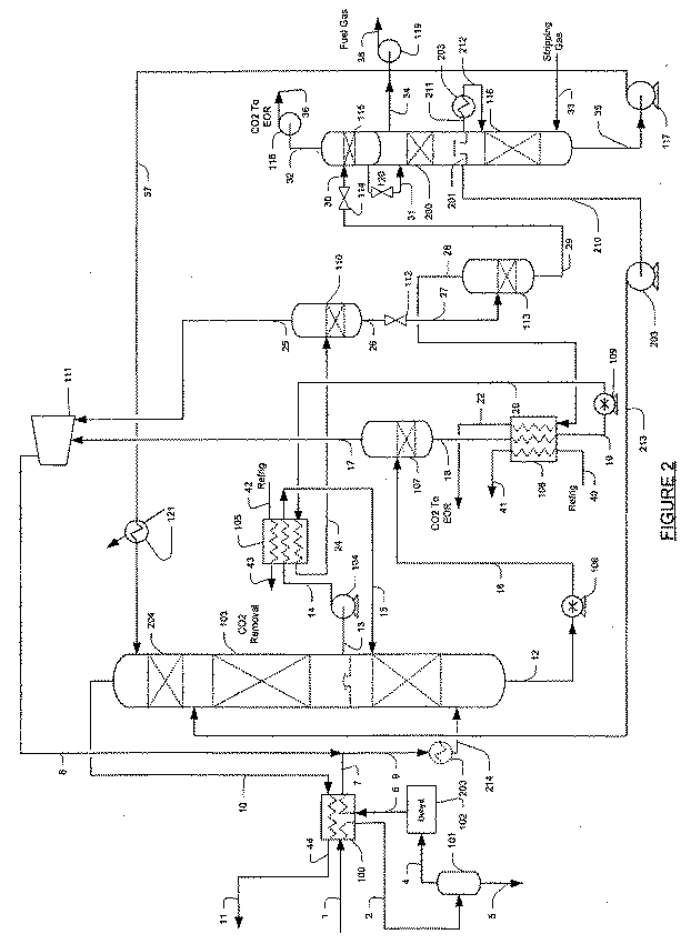
ppmレベル酸性ガス含有量仕様が生成ガスに要求される場合、図2に示される極端にストリップされた溶剤の構成が使用されてよい。このような構成は、酸性ガス吸収のための極端なリーン溶剤を生成することができる有利なストリッパ構成を含む、図1に示される代表的な構成に、一般的に基づく。ストリッパコラムは、収集器トレイ201により分離される上部分200および下部分116を一般的に有する。ストリッピング部分200は、収集トレイ201において収集される、部分的にストリップされた溶剤を生成する。一般的に溶剤流全体の50%から80%である流れ201は、リーン溶剤ポンプ203により収集トレイから引き込まれ、吸収装置103の中間部分に供給される。一般的に溶剤流全体の20%から50%である残りの流れ211は、熱交換器203においてフィードガス流9と共に一般的に約55°Fに加熱される。フィードガスは、流れ214を生成するために交換器203において一般的に−10°Fから20°Fに冷却される。ガスは脱水ユニット102において乾燥されているので、水の凍結は、全てまたはほとんど全ての場合において問題ではない。従って統合されたストリッパコラムは、吸収装置の異なる場所に供給される二つのストリップされた溶剤流を生成し、それによりストリッピング低部分において液体に対して高い蒸気率を維持することによって、極めてリーンな溶剤を生成することを特に認識されたい。
If a ppm level acid gas content specification is required for the product gas, the extremely stripped solvent configuration shown in FIG. 2 may be used. Such a configuration is generally based on the representative configuration shown in FIG. 1, including an advantageous stripper configuration that can produce an extreme lean solvent for acid gas absorption. The stripper column generally has an
適当なフィードガスに関し、多数の天然および合成フィードガスが適切であることが企図される。しかしながら特に好ましいフィードガスは、天然ガス、特に、少なくとも約5mol%、より一般的には少なくとも約10mol%、また最も一般的には少なくとも約20mol%である二酸化炭素を有する天然ガスを含む。従って特に適当なフィード流は、アラスカのPrudhoe BayまたはノルウェーのOrman Langeのような油田からの天然ガスフィード流を含む。同様に、適当なフィードガスの酸性ガス含有量(特に二酸化炭素含有量)は変動してよく、フィードガス源に主に依存する。しかしながら、酸性ガス含有量は少なくとも約5mol%、より一般的には少なくとも約10mol%、また最も一般的には少なくとも約20mol%であることが一般的に好ましい。一般的なフィード流組成は下記の表1に提供される。
更に、企図されるフィードガスの圧力は著しく変動してよく、適当な圧力は大気圧から数千psiの間に及ぶであろうことを認識されたい。しかしながら、フィードガスは少なくとも1000psig、より一般的には少なくとも2000psig、更により一般的には少なくとも3000psig、また最も一般的には少なくとも5000psigの圧力を有することが、特に好ましい。その上、フィードガス圧力の少なくとも一部はウェルに含有されるガスの圧力によることが一般的に企図されるが、適切な場合には圧力が一つ以上のコンプレッサを使用して増加されてもよいこともまた認識されたい。 Further, it should be recognized that the contemplated feed gas pressure may vary significantly, and that a suitable pressure will range between atmospheric and thousands of psi. However, it is particularly preferred that the feed gas has a pressure of at least 1000 psig, more typically at least 2000 psig, even more typically at least 3000 psig, and most typically at least 5000 psig. Moreover, it is generally contemplated that at least a portion of the feed gas pressure is due to the pressure of the gas contained in the well, although the pressure may be increased using one or more compressors where appropriate. It should also be recognized that it is good.
また更に企図される態様において、フィード流は吸収装置に入る前に冷却され、フィード流の冷却は、熱交換器における生成ガス(例えば吸収装置オーバーヘッド流)により少なくとも部分的に成されるであろうことが特に好ましい。冷却の程度に関し、フィード流は様々な温度に冷却されてよいことが一般的に企図される。しかしながら、フィード流がガス水和ポイントのほんの上の温度に冷却されることが一般的に好ましい。その結果、部分的に脱水されたフィードガスを形成するために、フィードガスに含有される水の少なくとも一部が冷却されたフィード流から除去される分離装置へ、冷却されたフィードガス流が供給されてよい。このように形成された部分的に脱水されたフィードガスは次いで、脱水ユニットにおいて更に脱水されてよく、また、全ての既知のガス脱水ユニットが使用に適していることを認識されたい。例えば、更なる脱水はグリコールまたはモレキュラーシーブを使用して実施されてよい。また更に好ましい態様において、脱水されたフィードガスは吸収装置に入る前に更に冷却されてよいことが企図される。特に好ましい企図される構成において、脱水されたフィードガスは熱交換器において冷却され、冷却は生成ガス(すなわち吸収装置オーバーヘッド流)により提供される。水が溶剤回路において凍結することなしに、吸収工程は著しく低い温度(例えば吸収装置において−20°Fから40°F)で行われることができるので、フィードガスの脱水は特に有利である。極めて低いレベルへの酸性ガス除去のための好ましい企図される構成において、脱水されたガスは、極端なストリッパ工程からの部分的にストリップされたリーン溶剤と共に、更に冷却されてよい。更に、低温度における吸収装置底部の動作は、減少された溶剤循環における吸収装置の動作を許し、従って能率を増加する。 In yet a further contemplated embodiment, the feed stream is cooled prior to entering the absorber, and cooling of the feed stream will be at least partially accomplished by product gas (eg, absorber overhead stream) in the heat exchanger. It is particularly preferred. With respect to the degree of cooling, it is generally contemplated that the feed stream may be cooled to various temperatures. However, it is generally preferred that the feed stream be cooled to a temperature just above the gas hydration point. As a result, the cooled feed gas stream is supplied to a separator where at least a portion of the water contained in the feed gas is removed from the cooled feed stream to form a partially dehydrated feed gas. May be. It will be appreciated that the partially dehydrated feed gas formed in this way may then be further dehydrated in a dehydration unit and that all known gas dehydration units are suitable for use. For example, further dehydration may be performed using glycols or molecular sieves. In a still further preferred embodiment, it is contemplated that the dehydrated feed gas may be further cooled before entering the absorber. In a particularly preferred contemplated configuration, the dehydrated feed gas is cooled in a heat exchanger, and cooling is provided by the product gas (ie, the absorber overhead stream). Feed gas dehydration is particularly advantageous because the absorption process can be performed at significantly lower temperatures (eg, -20 ° F to 40 ° F in the absorber) without water freezing in the solvent circuit. In a preferred contemplated configuration for acid gas removal to very low levels, the dehydrated gas may be further cooled along with the partially stripped lean solvent from the extreme stripper process. Furthermore, the operation of the absorber bottom at low temperatures allows the absorber operation in a reduced solvent circulation, thus increasing efficiency.
更に好ましい構成は、(例えばスカベンジャ床または硫黄仕様溶剤を有する付加的な吸収装置を介した)硫黄除去ユニットを更に含んでよく、また特に企図される硫黄除去ユニットは、(例えば吸収装置の上流位置の)フィードガスに含有される、硫化水素の少なくとも一部を除去する。あるいは、硫黄除去ユニットの補助なしに、工程は極端なストリッパ構成(上記を参照)を使用して、極めて低い酸性ガス含有量を有する処理されたガスを生成することができる。 Further preferred configurations may further include a sulfur removal unit (eg, via an additional absorber having a scavenger bed or sulfur-specific solvent), and a specifically contemplated sulfur removal unit (eg, upstream of the absorber) At least a portion of the hydrogen sulfide contained in the feed gas. Alternatively, without the aid of a sulfur removal unit, the process can use an extreme stripper configuration (see above) to produce a treated gas having a very low acid gas content.
従って、適当な吸収装置は比較的高圧力において動作し、特に企図される高圧力は、少なくとも1000psi、一般的には少なくとも2000psi、更により一般的には少なくとも3000psi、また最も一般的には少なくとも5000psiであることを、特に認識されたい。その結果、企図される吸収装置はガス相超臨界領域において動作することを認識されたい。ここで使用される「ガス相超臨界領域において動作する」という用語は、フィードガスの全てでない場合フィードガスの少なくとも一部は、物理的な液体およびガス相が存在しない超臨界状態であろうという条件のもとにおける、吸収装置の動作を指す。更に、ガス相超臨界領域において吸収工程を動作することにより、従来の既知の工程において一般に顕著な問題を引き起こす炭化水素の凝縮は、一般に回避される。更に企図される態様において、吸収装置の型は特定の構成に限定される必要が無く、全ての既知の吸収装置構成はここでの使用に適当であると考えられる。しかしながら、特に好ましい接触装置は充填層またはトレイ構成を含む。 Accordingly, suitable absorbers operate at relatively high pressures, and particularly contemplated high pressures are at least 1000 psi, typically at least 2000 psi, even more typically at least 3000 psi, and most typically at least 5000 psi. It should be particularly recognized that. As a result, it should be recognized that the contemplated absorber operates in the gas phase supercritical region. As used herein, the term “operating in the gas phase supercritical region” means that if not all of the feed gas, at least a portion of the feed gas will be in a supercritical state where there is no physical liquid and gas phase. Refers to the operation of the absorber under conditions. In addition, by operating the absorption process in the gas phase supercritical region, hydrocarbon condensation, which generally causes significant problems in the prior known processes, is generally avoided. In a further contemplated embodiment, the absorber type need not be limited to a particular configuration, and all known absorber configurations are considered suitable for use herein. However, particularly preferred contact devices include a packed bed or tray configuration.
企図される吸収装置において使用される溶剤に関し、全てのフィジカルな溶剤およびその混合物が適切であることを認識されたい。従来技術において既知の多数のフィジカルな溶剤が存在し、また代表的な好ましいフィジカルな溶剤は、プロピレンカーボネート、リン酸トリブチル、直鎖メチルピロリドン、ポリエチレングリコールのジメチルエーテル、および/または、様々なポリエチレングリコールジアルキルエーテルを含む。あるいは、増進第三アミン(例えばピペラジン)を含む別の溶剤か、またはその他の溶剤は、フィジカルな溶剤と同様な性質を有して使用されてよい。 It should be recognized that all physical solvents and mixtures thereof are suitable with respect to the solvents used in the contemplated absorbers. There are a number of physical solvents known in the prior art, and typical preferred physical solvents are propylene carbonate, tributyl phosphate, linear methylpyrrolidone, polyethylene glycol dimethyl ether, and / or various polyethylene glycol dialkyls. Contains ether. Alternatively, other solvents including enhanced tertiary amines (eg piperazine) or other solvents may be used with properties similar to physical solvents.
従って吸収装置は、酸性ガスから枯渇される、また特に二酸化炭素から枯渇される、生成ガスを提供するであろう。更に、吸収装置は冷却され脱水されたフィードガスを収容するので、高圧パイプラインを通る輸送手段のための、またはLNGプラントへのフィードガスとしての、販売用ガス仕様および必要条件の全て、またはほとんど全てに、生成ガスが一般的に適合するであろうことを認識されたい。吸収装置で形成されるリッチ溶剤は、比較的高圧力(例えば少なくとも1000psi、より一般的には2000から5000psiの間)で吸収装置底部を出て、従って(例えば電気エネルギー発生のための)動作および/または分離工程における様々な流れの冷却を提供するために、利用されてよいことを更に特に認識されたい。特に好ましい構成において、リッチ溶剤は機械または電気エネルギーを発生するための第一ハイドロリックタービンを使用して圧力において降下され、また減圧されたリッチ溶剤は次いで、分離装置において炭化水素含有第一リサイクル流および第一リッチ溶剤へ分離され、後に二酸化炭素流(二酸化炭素はフィードガスから生成される)を冷却するための冷却材として使用される。第一リッチ溶剤は、機械または電気エネルギーを更に発生するために第二ハイドロリックタービンを使用して更に減圧される一方、炭化水素含有第一リサイクル流は、好ましくは吸収装置へリサイクルされる。このように更に減圧されたリッチ溶剤流は次いで、所望の吸収装置底部温度を維持するために吸収装置のリッチ溶剤を冷却する、熱交換器の冷却材(好ましくは吸収装置のサイドクーラー)として使用される。熱交換器を通過した後、更に減圧されたリッチ溶剤流は次いで、第二分離装置において第二リッチ溶剤と、吸収装置にリサイクルされる第二炭化水素含有リサイクル流に分離される。その結果リッチ溶剤が通過され再生される前に、リッチ溶剤流は、少なくとも一つ、または高圧力を使用して動作および冷却を提供するために使用されることを認識されたい。 Thus, the absorber will provide a product gas that is depleted from acid gas, and in particular depleted from carbon dioxide. In addition, because the absorber contains cooled and dehydrated feed gas, all or most of the gas specifications and requirements for sale, for transportation through high pressure pipelines, or as feed gas to an LNG plant It should be recognized that all product gases will generally be compatible. The rich solvent formed in the absorber exits the absorber bottom at a relatively high pressure (eg, at least 1000 psi, more typically between 2000 and 5000 psi), thus operating (eg, for generating electrical energy) and It should be further appreciated that / or may be utilized to provide cooling of various streams in the separation process. In a particularly preferred configuration, the rich solvent is reduced in pressure using a first hydraulic turbine for generating mechanical or electrical energy, and the reduced rich solvent is then separated in a hydrocarbon-containing first recycle stream in a separator. And separated into a first rich solvent and later used as a coolant to cool the carbon dioxide stream (carbon dioxide is generated from the feed gas). The first rich solvent is further depressurized using a second hydraulic turbine to further generate mechanical or electrical energy, while the hydrocarbon-containing first recycle stream is preferably recycled to the absorber. This further decompressed rich solvent stream is then used as a heat exchanger coolant (preferably an absorber side cooler) that cools the absorber rich solvent to maintain the desired absorber bottom temperature. Is done. After passing through the heat exchanger, the further decompressed rich solvent stream is then separated in a second separator into a second rich solvent and a second hydrocarbon-containing recycle stream that is recycled to the absorber. As a result, it is recognized that the rich solvent stream is used to provide operation and cooling using at least one or high pressure before the rich solvent is passed through and regenerated.
リッチ溶剤の通過は様々な構成において実施されてよく、全ての既知の構成はここでの使用に適当であることが一般的に企図される。しかしながら、リッチ溶剤の圧力は、(動作および/または冷却を提供した後)溶解した二酸化炭素の少なくとも80%(より一般的には少なくとも90%、また最も一般的には少なくとも95%)を放すのに十分な圧力に、更に降下されることが一般的に好ましい。このように生成された二酸化炭素は次いで、(一般的に大気圧において動作する)分離装置においてリーン溶剤から分離される。このように発生された二酸化炭素流は、90%以上の、またより一般的には少なくとも95%の二酸化炭素含有量を有することを、特に認識されたい。従って、このように形成された二酸化炭素流は、石油増進回収工程で使用されるのに特に適する。 The passage of the rich solvent may be performed in a variety of configurations, and it is generally contemplated that all known configurations are suitable for use herein. However, the pressure of the rich solvent releases (after providing operation and / or cooling) at least 80% (more typically at least 90%, and most typically at least 95%) of the dissolved carbon dioxide. It is generally preferred that the pressure be further reduced to a sufficient pressure. The carbon dioxide thus produced is then separated from the lean solvent in a separation device (typically operating at atmospheric pressure). It should be particularly recognized that the carbon dioxide stream thus generated has a carbon dioxide content of 90% or more, and more typically at least 95%. Thus, the carbon dioxide stream thus formed is particularly suitable for use in an enhanced oil recovery process.
更に企図される本発明の主題の態様において、分離装置からのリーン溶剤はJTバルブを介して圧力において更に降下され、真空分離装置内に供給される。好ましい真空分離装置は、液体密閉真空ポンプにより発生される、約0.7から7.0psiaの間の圧力において動作する。(一般的に少なくとも95%の純度を有する)リーン溶剤からの残りの二酸化炭素は、真空分離装置において除去され、図1に描かれる石油増進回収において使用されてもよい。フィジカルな溶剤は次いで、ストリッパにおいて再生され、リーン溶剤ポンプを介して吸収装置に再循環される。特に好ましい構成においてストリッパは、燃料ガスを生成するためのストリッピングガスとして、リーンガス(例えば生成ガスの一部)を使用する。しかしながら代替の構成において、プラント内の別の流れからのガスと、窒素または空気さえも含む、生成ガス以外の様々なガスもまた適当である。このような構成におけるガスストリッパと結合した真空分離装置の使用は、一般的に1000ppmvより少ないCO2濃度を有する、極めてリーンな溶剤を生成することを、更に認識されたい。 In a further contemplated aspect of the present inventive subject matter, the lean solvent from the separator is further reduced in pressure through a JT valve and fed into the vacuum separator. A preferred vacuum separator operates at a pressure between about 0.7 and 7.0 psia generated by a liquid hermetic vacuum pump. The remaining carbon dioxide from the lean solvent (generally having a purity of at least 95%) may be removed in a vacuum separator and used in the enhanced oil recovery depicted in FIG. The physical solvent is then regenerated in a stripper and recycled to the absorber via a lean solvent pump. In a particularly preferred configuration, the stripper uses lean gas (eg, part of the product gas) as a stripping gas for producing fuel gas. However, in alternative configurations, various gases other than the product gas, including gases from another stream in the plant and even nitrogen or even air, are also suitable. It should further be appreciated that the use of a vacuum separator combined with a gas stripper in such a configuration produces a very lean solvent with a CO 2 concentration typically less than 1000 ppmv.
更に企図される態様において、特にガスがppmレベル酸性ガス仕様に処理される場合、極端にストリップされた溶剤の構成は、収集トレイにより分離される少なくとも二つの部分を含む優れたストリッパを含んでよく、吸収装置の異なる場所に供給される、部分的にストリップされた溶剤および極端にストリップされた溶剤を生成する。このような構成における極端なストリッパと結合した真空分離装置の使用は、一般的に100ppmvより少ないCO2濃度を有する、極端なリーン溶剤を生成するであろうことを、更に認識されたい。 In a further contemplated embodiment, particularly when the gas is processed to ppm level acid gas specifications, the extreme stripped solvent composition may include an excellent stripper that includes at least two parts separated by a collection tray. To produce partially stripped and extremely stripped solvent that is fed to different locations of the absorber. It should further be appreciated that the use of a vacuum separator combined with an extreme stripper in such a configuration will produce an extreme lean solvent, generally having a CO 2 concentration of less than 100 ppmv.
従って、特に好ましい構成において、フィードガスが天然ガスを含む場合、生成ガスはフィードガスに存在する天然ガスの少なくとも90%、より一般的には少なくとも95%、また最も一般的には少なくとも99%を含むことを認識されたい。いずれの学説または仮説に結び付けられるのを要求するものではないが、生成ガスにおけるこのような比較的高い天然ガス回収は、少なくとも一つ、またより好ましくは二つの炭化水素含有リサイクル流を吸収装置に戻すことにより、達成されることが企図される。従って、生成された二酸化炭素流の純度は比較的高く、このように形成された二酸化炭素流は一般的に少なくとも90%、またより一般的には少なくとも95%のCO2を含むであろう。 Thus, in a particularly preferred configuration, when the feed gas comprises natural gas, the product gas will comprise at least 90%, more typically at least 95%, and most typically at least 99% of the natural gas present in the feed gas. Recognize that it includes. Although not required to be tied to any theory or hypothesis, such a relatively high natural gas recovery in the product gas will result in at least one and more preferably two hydrocarbon-containing recycle streams to the absorber. It is contemplated that this is accomplished by returning. Thus, the purity of the generated carbon dioxide stream is relatively high, thus formed carbon dioxide stream is generally at least 90%, also will more typically at least 95% of the CO 2.
適当なリサイクルガスコンプレッサは、第一および第二炭化水素含有リサイクルガス流を、冷却され脱水されたフィードガスの圧力と等しいか、またはその周辺の圧力に圧縮することが可能な、全てのコンプレッサである。同様に、リーン溶剤ポンプは、リーン溶剤の吸収装置への導入に適当な溶剤圧力を提供するであろうことが企図される。 Suitable recycle gas compressors are all compressors capable of compressing the first and second hydrocarbon-containing recycle gas streams to a pressure equal to or around the pressure of the cooled and dehydrated feed gas. is there. Similarly, it is contemplated that the lean solvent pump will provide a suitable solvent pressure for introduction of the lean solvent into the absorber.
従ってプラントは、少なくとも5mol%の二酸化炭素を含む、少なくとも1000psiの圧力でのフィードガスを受け取る吸収装置を含んでよく、吸収装置は、リッチ溶剤、および二酸化炭素から少なくとも部分的に枯渇される生成ガス、を生成するためにフィジカルな溶剤を使用する。企図されるプラントは、リッチ溶剤を減圧する第一タービンと、第一炭化水素部分を減圧されたリッチ溶剤から分離する第一分離装置、を更に含み、それにより第一炭化水素リサイクル流および第一リッチ溶剤を生成し、また第一リッチ溶剤を更に減圧する第二タービンと、吸収装置の底部温度を所望の温度範囲に維持するためにフィジカルな溶剤を冷却するよう更に減圧された第一溶剤を使用するクーラー、を更に含んでよく、更に減圧された第一溶剤は、第二炭化水素部分を更に減圧された第一溶剤から分離する第二分離装置において分離され、それにより第二炭化水素リサイクル流および第二リッチ溶剤を生成し、また第一および第二炭化水素リサイクル流は吸収装置に供給される。 Accordingly, the plant may include an absorber that receives a feed gas at a pressure of at least 1000 psi, comprising at least 5 mol% carbon dioxide, the absorber being a rich solvent and a product gas that is at least partially depleted from carbon dioxide. , To use a physical solvent. The contemplated plant further includes a first turbine that depressurizes the rich solvent and a first separator that separates the first hydrocarbon portion from the depressurized rich solvent, whereby the first hydrocarbon recycle stream and the first A second turbine that produces a rich solvent and further depressurizes the first rich solvent, and a first solvent that is further depressurized to cool the physical solvent to maintain the bottom temperature of the absorber in the desired temperature range. A cooler for use, and the further reduced pressure first solvent is separated in a second separation device that separates the second hydrocarbon portion from the further reduced pressure first solvent, thereby recycling the second hydrocarbon. The stream and the second rich solvent are produced, and the first and second hydrocarbon recycle streams are fed to the absorber.
フィードガス、吸収装置、フィジカルな溶剤、二酸化炭素流、および様々な別の構成要素に関し、上に論じたものと同じ考察が適用される。従って、特に企図されるフィードガスは生成ガスにより少なくとも部分的に脱水、冷却され、また吸収装置に入る前に脱水ユニットにおいて更に脱水されてよい。更に、企図される第二リッチ溶剤は、二酸化炭素の少なくとも一部を除去するために更に減圧されてよく、それにより(リーンガスを使用し、燃料ガスを生成する真空分離装置において更に処理されてよく、それによりフィジカルな溶剤を再生する)リーン溶剤を形成する一方、企図される第一リッチ溶剤は二酸化炭素流を冷却するための冷却材として使用されてよい。特に企図されるフィジカルな溶剤はプロピレンカーボネートを含み、二酸化炭素が石油増進回収において使用されることが特に好ましい。 The same considerations as discussed above apply with respect to the feed gas, absorber, physical solvent, carbon dioxide stream, and various other components. Thus, the particularly contemplated feed gas may be at least partially dehydrated and cooled by the product gas and further dehydrated in the dehydration unit before entering the absorber. Further, the contemplated second rich solvent may be further depressurized to remove at least a portion of the carbon dioxide and thereby be further processed in a vacuum separator that uses lean gas and produces fuel gas. The contemplated first rich solvent may be used as a coolant to cool the carbon dioxide stream, while forming a lean solvent (which regenerates the physical solvent). Particularly contemplated physical solvents include propylene carbonate, and it is particularly preferred that carbon dioxide be used in enhanced oil recovery.
従ってプラントを動作する方法は、酸性ガスを含む、少なくとも1000psiの圧力のフィードガスを受け取る吸収装置が提供される一つの工程を含んでよい。別の工程において、酸性ガスの少なくとも一部はフィジカルな溶剤を使用してフィードガスから除去され、それにより生成ガスおよびリッチ溶剤を形成し、また更なる工程において、リッチ溶剤の圧力は吸収装置に供給される炭化水素リサイクル流を形成するよう減少され、それにより減圧されたリッチ溶剤を生成する。また別の工程において、減圧されたリッチ溶剤はフィジカルな溶剤を冷却するために使用され、それにより吸収装置の底部温度を所望の温度範囲に維持し、加熱され減圧されたリッチ溶剤を形成し、また更なる工程において、加熱され減圧されたリッチ溶剤は酸性ガスの少なくとも一部を含む流れに分離され、それによりリーン溶剤を形成する。 Thus, a method of operating a plant may include one step in which an absorber is provided that receives a feed gas at a pressure of at least 1000 psi, including an acid gas. In another step, at least a portion of the acid gas is removed from the feed gas using a physical solvent, thereby forming a product gas and a rich solvent, and in a further step, the rich solvent pressure is applied to the absorber. A rich solvent is produced that is reduced to form a feed hydrocarbon recycle stream and thereby reduced pressure. In another step, the decompressed rich solvent is used to cool the physical solvent, thereby maintaining the bottom temperature of the absorber in the desired temperature range, forming a heated and decompressed rich solvent, In yet a further step, the heated and depressurized rich solvent is separated into a stream containing at least a portion of the acid gas, thereby forming a lean solvent.
フィードガス、吸収装置、フィジカルな溶剤、二酸化炭素流、および様々な別の構成要素に関し、上に論じたものと同じ考察が適用される。従って、特に企図されるフィードガスは、約3000psiから約5000psiの間の圧力を有してよい。企図される酸性ガスは二酸化炭素を特に含み、フィジカルな溶剤はプロピレンカーボネートを含む。更に企図される態様において、リーン溶剤はリーンガスを使用して真空分離装置において処理され、それにより燃料ガスを生成し、フィジカルな溶剤を再生する。 The same considerations as discussed above apply with respect to the feed gas, absorber, physical solvent, carbon dioxide stream, and various other components. Thus, a particularly contemplated feed gas may have a pressure between about 3000 psi and about 5000 psi. The contemplated acid gas specifically includes carbon dioxide and the physical solvent includes propylene carbonate. In a further contemplated embodiment, the lean solvent is processed in a vacuum separator using lean gas, thereby producing fuel gas and regenerating the physical solvent.
従って、本発明の主題による構成は、アミンまたは別のフィジカルな溶剤または膜を使用する、高いフィードガス圧力での従来技術のCO2除去工程と比較して、全体のエネルギー消費および資本コストを著しく減少するであろうことが企図される。更に、企図される構成および工程は一般的に熱源を必要とせず、それによりエネルギー消費を更に減少する。また更に、石油増進回収プロジェクトは、一般的に10%から60%ほどまで高い、フィードガスにおけるCO2濃度の増加にしばしば直面するであろう。企図される構成および工程は、実質的に同じ溶剤循環と共にこれらの変化に適応することができる。 Therefore, the configuration according to the subject matter of the present invention uses the amine or another physical solvents or membranes, as compared with the prior art CO 2 removal process at high feed gas pressure, significantly overall energy consumption and capital cost It is contemplated that it will decrease. Furthermore, the contemplated configurations and processes generally do not require a heat source, thereby further reducing energy consumption. Furthermore, enhanced oil recovery projects, generally high 10% to about 60%, will often face increased CO 2 concentration in the feed gas. Contemplated configurations and processes can accommodate these changes with substantially the same solvent circulation.
更に企図される構成は、低温度での動作およびフィジカルな溶剤における水の不足のために、非腐食性工程を一般的に提供する。一方、このような工程は腐食する傾向にあり、動作の間、消泡剤および非腐食投入をしばしば必要とするので、従来技術の二酸化炭素除去のためのアミンユニットは一般的に、動作および維持するのにより複雑である。また更に、企図されるフィジカルな溶剤工程の別の利点は、アミン工程と異なり、溶剤循環率がCO2部分圧力における増加に反応しないことである(例えば20%のCO2を含有する100MMSCFDのガスを処理するのに必要なフィジカルな溶剤率は、60%のCO2を含有する100MMSCFDのガスを処理するのに必要なそれと実質的に同じである。溶剤に加えられるCO2は、フィードガスにおける増加するCO2濃度と共に単に増加する。アミンユニット設計においてアミン循環率は、リッチアミン溶剤に加えられる、維持されなければならないCO2の約3倍である)。 Further contemplated configurations generally provide a non-corrosive process due to low temperature operation and lack of water in physical solvents. On the other hand, such units tend to corrode and often require antifoam and non-corrosive inputs during operation, so prior art amine units for carbon dioxide removal are generally operational and maintainable. It is more complicated to do. Still further, another advantage of the contemplated physical solvent process is that, unlike the amine process, the solvent circulation rate does not react to the increase in CO 2 partial pressure (eg, 100 MMS CFD gas containing 20% CO 2 physical solvents rate required to process the is substantially the same as required to process 100MMSCFD of gas containing 60% CO 2. CO 2 to be added in a solvent, in the feed gas It simply increases with increasing CO 2 concentration. In the amine unit design, the amine cycling rate is about three times the CO 2 that is added to the rich amine solvent and must be maintained).
企図されるフィジカルな溶剤工程のまた別の利点は、既知のアミン処理工程と比較して、その容易さおよび凍結への耐性であり、従って、スチームボイラーのような支援オフサイトおよび効用システムを必要とすることが少ない。例えば、企図される構成は一般的に冷却のみを必要とし、残りのCO2含有量が5から10psia範囲にある場合、発明者は溶剤再生のための高温オイルシステムなしのプラントの動作を企図する。更に、比較的高いCO2フィードガスにおいて動作する場合、溶剤再生からのCO2の通過は必要な冷却を提供するので、溶剤冷却のための冷却必要条件は完全に取り除かれてよい。 Another advantage of the contemplated physical solvent process is its ease and resistance to freezing compared to known amine treatment processes, thus requiring a assisted offsite and utility system such as a steam boiler And rarely. For example, contemplated configurations typically require only cooling, and the inventors contemplate operation of a plant without a high temperature oil system for solvent regeneration when the remaining CO 2 content is in the 5 to 10 psia range. . Furthermore, when operating at a relatively high CO 2 feed gas, the passage of CO 2 from solvent regeneration provides the necessary cooling so that the cooling requirements for solvent cooling may be completely eliminated.
本発明のまた別の利点は、CO2が50ppmv範囲内であり、H2Sが4ppmv範囲内であることを要求するLNGプラントに、フィードガス仕様が適合するよう処理することである。説明した極端なストリッパの最近の発明への包括は、直接に適用可能である。 Another advantage of the present invention is that the feed gas specifications are processed to meet LNG plants that require CO 2 in the 50 ppmv range and H 2 S in the 4 ppmv range. The inclusion of the described extreme stripper in the recent invention is directly applicable.
従って、改善された酸性ガス除去のための構成および方法のための特定の実施形態と適用が開示される。しかしながら、本発明の趣旨から外れることなく、既に説明したことの他にも多くの修正が可能であることが、当業者にとって明白である。本発明の主題は従って、添付の企図される特許請求の範囲の精神において以外に、限定されるものではない。更に、明細書および企図される特許請求の範囲の両方の解釈において、全ての用語は文脈と首尾一貫した、可能な限り広範囲な方法において解釈されたい。特に、「含む」および「含んでいる」という用語は、参照された要素、成分、または工程が、明確に参照されていない別の要素、成分、または工程と共に存在するか、利用されるか、または結合されることを示す、非独占的な方法における要素、成分、または工程の言及として解釈されたい。 Accordingly, specific embodiments and applications for configurations and methods for improved acid gas removal are disclosed. However, it will be apparent to those skilled in the art that many more modifications besides those already described are possible without departing from the spirit of the invention. The subject matter of the invention is therefore not to be restricted except in the spirit of the appended contemplated claims. Moreover, in interpreting both the specification and the intended claims, all terms should be interpreted in the broadest possible manner consistent with the context. In particular, the terms “comprising” and “comprising” indicate that a referenced element, component, or process exists or is utilized with another element, component, or process that is not explicitly referred to, Or to be construed as a reference to an element, component, or process in a non-proprietary manner indicating that they are combined.
Claims (25)
リッチ溶剤を減圧する第一タービンと、減圧されたリッチ溶剤から第一炭化水素部分を分離し、それにより第一炭化水素リサイクル流および第一リッチ溶剤を生成する第一分離装置と、
第一リッチ溶剤を更に減圧する第二タービンと、吸収装置の底部温度を所望の温度範囲に維持するよう物理溶剤を冷却するための、更に減圧された第一溶剤を使用するクーラーと、を含み、
更に減圧された第一溶剤は、更に減圧された第一溶剤から第二炭化水素部分を分離する第二分離装置において分離され、それにより第二炭化水素リサイクル流および第二リッチ溶剤を生成し、第一および第二炭化水素リサイクル流は吸収装置に供給され、
ストリッパが、第二リッチ溶剤からリーンな物理溶剤を再生する、
プラント。An absorber that receives a dehydrated feed gas containing at least 5 mol% carbon dioxide and operates in the gas phase supercritical region, wherein the absorber produces a product gas that is at least partially depleted of rich solvent and carbon dioxide. To use a lean physical solvent to absorb,
A first turbine that depressurizes the rich solvent, a first separator that separates the first hydrocarbon portion from the depressurized rich solvent, thereby producing a first hydrocarbon recycle stream and a first rich solvent;
A second turbine that further depressurizes the first rich solvent, and a cooler that uses the further depressurized first solvent to cool the physical solvent to maintain the bottom temperature of the absorber in a desired temperature range. ,
The further reduced pressure first solvent is separated in a second separator that separates the second hydrocarbon portion from the further reduced pressure first solvent, thereby producing a second hydrocarbon recycle stream and a second rich solvent, The first and second hydrocarbon recycle streams are fed to the absorber
Stripper regenerates lean physical solvent from second rich solvent,
plant.
リーンな物理溶剤を使用して二酸化炭素の少なくとも一部をフィードガスから除去し、それにより生成ガスおよびリッチ溶剤を形成することと、
吸収装置に供給される炭化水素リサイクル流を形成するようリッチ溶剤の圧力を減少し、それにより減圧されたリッチ溶剤を生成することと、
物理溶剤を冷却するために減圧されたリッチ溶剤を使用し、それにより吸収装置の底部温度を所望の温度範囲に維持し、加熱され減圧されたリッチ溶剤を形成すること、および
加熱され減圧されたリッチ溶剤を、二酸化炭素の少なくとも一部を含む流れと、リーン溶剤とに分離すること、を含む、
プラントを動作する方法。Providing an absorber that receives a dehydrated feed gas comprising at least 5 mol% carbon dioxide and operates in a gas phase supercritical region;
Removing at least a portion of the carbon dioxide from the feed gas using a lean physical solvent, thereby forming a product gas and a rich solvent;
Reducing the pressure of the rich solvent to form a hydrocarbon recycle stream fed to the absorber, thereby producing a decompressed rich solvent;
Use the reduced rich solvent to cool the physical solvent, thereby maintaining the bottom temperature of the absorber in the desired temperature range, forming a heated and reduced rich solvent, and heated and reduced pressure rich solvent, comprising a stream comprising at least a portion of the carbon dioxide, it is separated into a rie down solvent, and
How to operate the plant.
Applications Claiming Priority (1)
| Application Number | Priority Date | Filing Date | Title |
|---|---|---|---|
| PCT/US2002/012050 WO2003089115A1 (en) | 2002-04-15 | 2002-04-15 | Configurations and methods for improved acid gas removal |
Publications (2)
| Publication Number | Publication Date |
|---|---|
| JP2005522326A JP2005522326A (en) | 2005-07-28 |
| JP4771663B2 true JP4771663B2 (en) | 2011-09-14 |
Family
ID=29247984
Family Applications (1)
| Application Number | Title | Priority Date | Filing Date |
|---|---|---|---|
| JP2003585859A Expired - Fee Related JP4771663B2 (en) | 2002-04-15 | 2002-04-15 | Configuration and method for improved acid gas removal |
Country Status (6)
| Country | Link |
|---|---|
| JP (1) | JP4771663B2 (en) |
| CN (1) | CN100337722C (en) |
| AU (1) | AU2002307364C1 (en) |
| CA (1) | CA2482159C (en) |
| MX (1) | MXPA04010112A (en) |
| WO (1) | WO2003089115A1 (en) |
Families Citing this family (32)
| Publication number | Priority date | Publication date | Assignee | Title |
|---|---|---|---|---|
| EP1781400B1 (en) | 2004-08-06 | 2013-07-03 | ALSTOM Technology Ltd | Cleaning of combustion gas including the removal of co2 |
| AR068841A1 (en) * | 2007-10-12 | 2009-12-09 | Union Engeneering As | REMOVAL OF CARBON DIOXIDE FROM A POWER GAS |
| US8182577B2 (en) | 2007-10-22 | 2012-05-22 | Alstom Technology Ltd | Multi-stage CO2 removal system and method for processing a flue gas stream |
| DE102007056625B3 (en) * | 2007-11-23 | 2008-09-04 | Lurgi Gmbh | Method for treating a process gas stream containing carbon dioxide during the production of pure synthesis gas from crude comprises compressing contaminated carbon dioxide and removing the impurities by stripping |
| US7862788B2 (en) | 2007-12-05 | 2011-01-04 | Alstom Technology Ltd | Promoter enhanced chilled ammonia based system and method for removal of CO2 from flue gas stream |
| US7846240B2 (en) | 2008-10-02 | 2010-12-07 | Alstom Technology Ltd | Chilled ammonia based CO2 capture system with water wash system |
| US8404027B2 (en) | 2008-11-04 | 2013-03-26 | Alstom Technology Ltd | Reabsorber for ammonia stripper offgas |
| RU2011142912A (en) * | 2009-03-25 | 2013-04-27 | Флуор Текнолоджиз Корпорейшн | IMPROVED PROCESS DIAGRAMS AND METHODS FOR REMOVING ACID HIGH PRESSURE GASES |
| US8292989B2 (en) | 2009-10-30 | 2012-10-23 | Alstom Technology Ltd | Gas stream processing |
| US8790605B2 (en) | 2009-09-15 | 2014-07-29 | Alstom Technology Ltd | Method for removal of carbon dioxide from a process gas |
| US8784761B2 (en) | 2009-11-20 | 2014-07-22 | Alstom Technology Ltd | Single absorber vessel to capture CO2 |
| US8518156B2 (en) | 2009-09-21 | 2013-08-27 | Alstom Technology Ltd | Method and system for regenerating a solution used in a wash vessel |
| EP2322265A1 (en) | 2009-11-12 | 2011-05-18 | Alstom Technology Ltd | Flue gas treatment system |
| US8293200B2 (en) | 2009-12-17 | 2012-10-23 | Alstom Technology Ltd | Desulfurization of, and removal of carbon dioxide from, gas mixtures |
| US9295940B2 (en) | 2010-02-17 | 2016-03-29 | Fluor Technologies Corporation | Configurations and methods for high pressure acid gas removal in the production of ultra-low sulfur gas |
| US8728209B2 (en) | 2010-09-13 | 2014-05-20 | Alstom Technology Ltd | Method and system for reducing energy requirements of a CO2 capture system |
| US8623307B2 (en) | 2010-09-14 | 2014-01-07 | Alstom Technology Ltd. | Process gas treatment system |
| US8329128B2 (en) | 2011-02-01 | 2012-12-11 | Alstom Technology Ltd | Gas treatment process and system |
| US9028784B2 (en) | 2011-02-15 | 2015-05-12 | Alstom Technology Ltd | Process and system for cleaning a gas stream |
| CN102797650A (en) * | 2011-05-27 | 2012-11-28 | 中国科学院工程热物理研究所 | Low-CO2-emisison solar energy and methanol complementary thermodynamic cycle system and method |
| US9162177B2 (en) | 2012-01-25 | 2015-10-20 | Alstom Technology Ltd | Ammonia capturing by CO2 product liquid in water wash liquid |
| US8864879B2 (en) | 2012-03-30 | 2014-10-21 | Jalal Askander | System for recovery of ammonia from lean solution in a chilled ammonia process utilizing residual flue gas |
| US9671162B2 (en) | 2012-10-24 | 2017-06-06 | Fluor Technologies Corporation | Integration methods of gas processing plant and nitrogen rejection unit for high nitrogen feed gases |
| DE102012021478A1 (en) * | 2012-11-05 | 2014-05-08 | Thyssenkrupp Uhde Gmbh | Method and apparatus for removing absorbable gases from pressurized, gas-contaminated industrial gases without supplying cooling energy |
| US9764272B2 (en) * | 2013-10-28 | 2017-09-19 | Energy Recovery, Inc. | Systems and methods for utilizing turbine systems within gas processing systems |
| US10000713B2 (en) | 2013-12-12 | 2018-06-19 | Fluor Technologies Corporation | Configurations and methods of flexible CO2 removal |
| CN103897760B (en) * | 2014-04-10 | 2016-01-20 | 开封黄河空分集团有限公司 | Methane purification system |
| CN108012532B (en) * | 2015-08-19 | 2021-08-20 | 卡萨尔公司 | Method for retrofitting a CO2 removal section for purifying hydrogen-containing gases |
| DE102015013796A1 (en) * | 2015-10-22 | 2017-04-27 | Linde Aktiengesellschaft | Process and apparatus for recovering gas products |
| CN108722140B (en) * | 2017-04-13 | 2021-03-02 | 中国石油化工股份有限公司 | Acid gas treatment process and system |
| CN108722149B (en) * | 2017-04-13 | 2021-05-04 | 中国石油化工股份有限公司 | Method and device for treating acid gas |
| CN108722135B (en) * | 2017-04-13 | 2021-03-02 | 中国石油化工股份有限公司 | Acid gas combined treatment process and system |
Citations (2)
| Publication number | Priority date | Publication date | Assignee | Title |
|---|---|---|---|---|
| US4533373A (en) * | 1982-12-23 | 1985-08-06 | Linde Aktiengesellschaft | Separation of CO2 and H2 S from hydrogen containing gas |
| JPS60153921A (en) * | 1983-12-20 | 1985-08-13 | シエル・インターナシヨネイル・リサーチ・マーチヤツピイ・ベー・ウイ | Removal of h2s from sour h2s-containing gas stream |
Family Cites Families (10)
| Publication number | Priority date | Publication date | Assignee | Title |
|---|---|---|---|---|
| DE1095866B (en) * | 1959-09-30 | 1960-12-29 | Linde S Eismaschinen Ag Zweign | Process and device for the separation of carbon dioxide from compressed gases |
| US3252269A (en) * | 1962-12-27 | 1966-05-24 | Union Oil Co | Removal of acid constituents from gas mixtures using acetoxy acetone |
| DE1544080B2 (en) * | 1965-11-15 | 1974-12-12 | Metallgesellschaft Ag, 6000 Frankfurt | Process for cleaning highly compressed gases containing carbon dioxide |
| DE1501720B1 (en) * | 1965-11-15 | 1970-07-09 | Linde Ag | Process for separating CO2 and H2S from gas mixtures |
| US3664091A (en) * | 1969-06-27 | 1972-05-23 | Fish Engineering & Constructio | Process and system for removing acid gas from natural gas |
| DE2262457A1 (en) * | 1972-12-20 | 1974-06-27 | Linde Ag | PROCESS AND DEVICE FOR WASHING OUT CARBON DIOXIDE, HYDROGEN SULFUR AND, IF APPLICABLE, CARBON OXISULFIDE |
| US4252548A (en) * | 1979-01-02 | 1981-02-24 | Kryos Energy Inc. | Carbon dioxide removal from methane-containing gases |
| US4576615A (en) * | 1984-08-20 | 1986-03-18 | The Randall Corporation | Carbon dioxide hydrocarbons separation process |
| CN1028011C (en) * | 1991-03-25 | 1995-03-29 | 杭州市化工研究所 | 3-c hydrocarbon decarbonizing process and device thereof |
| CA2177449C (en) * | 1996-05-20 | 2003-04-29 | Barry Steve Marjanovich | Process for treating a gas stream to selectively separate acid gases therefrom |
-
2002
- 2002-04-15 AU AU2002307364A patent/AU2002307364C1/en not_active Ceased
- 2002-04-15 MX MXPA04010112A patent/MXPA04010112A/en active IP Right Grant
- 2002-04-15 WO PCT/US2002/012050 patent/WO2003089115A1/en not_active Ceased
- 2002-04-15 CA CA002482159A patent/CA2482159C/en not_active Expired - Lifetime
- 2002-04-15 CN CNB028291336A patent/CN100337722C/en not_active Expired - Fee Related
- 2002-04-15 JP JP2003585859A patent/JP4771663B2/en not_active Expired - Fee Related
Patent Citations (2)
| Publication number | Priority date | Publication date | Assignee | Title |
|---|---|---|---|---|
| US4533373A (en) * | 1982-12-23 | 1985-08-06 | Linde Aktiengesellschaft | Separation of CO2 and H2 S from hydrogen containing gas |
| JPS60153921A (en) * | 1983-12-20 | 1985-08-13 | シエル・インターナシヨネイル・リサーチ・マーチヤツピイ・ベー・ウイ | Removal of h2s from sour h2s-containing gas stream |
Also Published As
| Publication number | Publication date |
|---|---|
| CN1627980A (en) | 2005-06-15 |
| AU2002307364C1 (en) | 2008-07-10 |
| WO2003089115A1 (en) | 2003-10-30 |
| CA2482159C (en) | 2009-08-11 |
| CA2482159A1 (en) | 2003-10-30 |
| JP2005522326A (en) | 2005-07-28 |
| AU2002307364B2 (en) | 2007-05-31 |
| AU2002307364A1 (en) | 2003-11-03 |
| MXPA04010112A (en) | 2004-12-13 |
| CN100337722C (en) | 2007-09-19 |
Similar Documents
| Publication | Publication Date | Title |
|---|---|---|
| JP4771663B2 (en) | Configuration and method for improved acid gas removal | |
| US7192468B2 (en) | Configurations and method for improved gas removal | |
| JP4105697B2 (en) | Acid gas removal plant and method | |
| JP4673624B2 (en) | Configuration and method for removing acid gases | |
| CN102448580B (en) | Improved configurations apparatus and methods for high pressure acid gas removal | |
| US10384160B2 (en) | Configurations and methods of high pressure acid gas removal in the production of ultra-low sulfur gas | |
| JP2006509622A5 (en) | ||
| US20130032029A1 (en) | Gas purification configurations and methods | |
| JP2005538841A5 (en) | ||
| JP2006507389A (en) | Configuration and method of high pressure gas treatment | |
| US9844751B2 (en) | Method and apparatus for removing absorbable gases from pressurized industrial gases contaminated with absorbable gases, without supplying cooling energy | |
| JP5036183B2 (en) | Improved solvent use and regeneration | |
| AU2007201677B2 (en) | Configurations and methods for improved acid gas removal |
Legal Events
| Date | Code | Title | Description |
|---|---|---|---|
| A131 | Notification of reasons for refusal |
Free format text: JAPANESE INTERMEDIATE CODE: A131 Effective date: 20080617 |
|
| A601 | Written request for extension of time |
Free format text: JAPANESE INTERMEDIATE CODE: A601 Effective date: 20080911 |
|
| A602 | Written permission of extension of time |
Free format text: JAPANESE INTERMEDIATE CODE: A602 Effective date: 20080919 |
|
| A521 | Request for written amendment filed |
Free format text: JAPANESE INTERMEDIATE CODE: A523 Effective date: 20081215 |
|
| A131 | Notification of reasons for refusal |
Free format text: JAPANESE INTERMEDIATE CODE: A131 Effective date: 20100323 |
|
| A601 | Written request for extension of time |
Free format text: JAPANESE INTERMEDIATE CODE: A601 Effective date: 20100617 |
|
| A602 | Written permission of extension of time |
Free format text: JAPANESE INTERMEDIATE CODE: A602 Effective date: 20100624 |
|
| A521 | Request for written amendment filed |
Free format text: JAPANESE INTERMEDIATE CODE: A523 Effective date: 20100922 |
|
| A131 | Notification of reasons for refusal |
Free format text: JAPANESE INTERMEDIATE CODE: A131 Effective date: 20101122 |
|
| A601 | Written request for extension of time |
Free format text: JAPANESE INTERMEDIATE CODE: A601 Effective date: 20110216 |
|
| A602 | Written permission of extension of time |
Free format text: JAPANESE INTERMEDIATE CODE: A602 Effective date: 20110223 |
|
| A521 | Request for written amendment filed |
Free format text: JAPANESE INTERMEDIATE CODE: A523 Effective date: 20110519 |
|
| TRDD | Decision of grant or rejection written | ||
| A01 | Written decision to grant a patent or to grant a registration (utility model) |
Free format text: JAPANESE INTERMEDIATE CODE: A01 Effective date: 20110614 |
|
| A01 | Written decision to grant a patent or to grant a registration (utility model) |
Free format text: JAPANESE INTERMEDIATE CODE: A01 |
|
| A61 | First payment of annual fees (during grant procedure) |
Free format text: JAPANESE INTERMEDIATE CODE: A61 Effective date: 20110621 |
|
| FPAY | Renewal fee payment (event date is renewal date of database) |
Free format text: PAYMENT UNTIL: 20140701 Year of fee payment: 3 |
|
| R150 | Certificate of patent or registration of utility model |
Free format text: JAPANESE INTERMEDIATE CODE: R150 |
|
| R250 | Receipt of annual fees |
Free format text: JAPANESE INTERMEDIATE CODE: R250 |
|
| LAPS | Cancellation because of no payment of annual fees |