JP4769397B2 - In-vehicle information equipment - Google Patents
In-vehicle information equipment Download PDFInfo
- Publication number
- JP4769397B2 JP4769397B2 JP2001338549A JP2001338549A JP4769397B2 JP 4769397 B2 JP4769397 B2 JP 4769397B2 JP 2001338549 A JP2001338549 A JP 2001338549A JP 2001338549 A JP2001338549 A JP 2001338549A JP 4769397 B2 JP4769397 B2 JP 4769397B2
- Authority
- JP
- Japan
- Prior art keywords
- image
- operator
- operation unit
- vehicle information
- viewpoint
- Prior art date
- Legal status (The legal status is an assumption and is not a legal conclusion. Google has not performed a legal analysis and makes no representation as to the accuracy of the status listed.)
- Expired - Fee Related
Links
Images


Description
【0001】
【発明の属する技術分野】
本発明は、操作部の画像を表示手段に表示しこれを見ながら操作部を操作する車載用情報機器に関するものである。
【0002】
【従来の技術】
一般に、車載機器には複数のボタンやボリュームを有するパネル状の操作部が配置されている。この操作部を操作する場合、操作者はボタンやボリュームの位置を視線にて確認しながらその位置まで手を伸ばし、目的のボタンあるいはボリュームを選択するといった動作をとっている。以上の動作を行う操作者が車両を運転している場合、操作者は視線を前方に保持しなくてはならず、できるだけ安定した運転姿勢を維持する必要がある。そのため、操作部の取付位置は、操作者が運転をしている状態で自然に目に入る領域(以下、ここでは運転視界と呼ぶ)の内側である方が望ましい。
【0003】
しかし、車両のスペースには制約があり、運転視界内に操作部を取付けることは実質的に困難である。そのため、運転視界からは多少外れた位置に操作部を取り付けざるを得ない。したがって、操作者が視線を前方に保持した状態では操作部を手探りで操作することが多く、操作性が低かった。車載機器の操作性に関しては安全性重視の観点から非常に高いレベルが要求されている。そこで従来より、運転視界内にディスプレイ装置を取り付け、該ディスプレイ装置上に操作部の画像を表示する車載用情報機器が提案されている。
【0004】
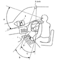
このような車載用情報機器の従来例について、図15を参照して説明する。右ハンドル車の運転者を操作者と想定した場合、機器本体1および操作部2は運転席に座っている操作者の左前方に配置されている。機器本体1は車載用CDプレーヤを含む音響機器を主体としたもので、CDの一般的な再生に必要な操作などを実現する。その操作に必要なスイッチやCDの入れ替えに関しては操作部2前面にて操作を実施する。また、操作部2の画像を取得するためのカメラ3が車両の天井に固定されている。このとき、カメラ3は操作者の腕などで操作部2の操作状況が隠れない画像を取ることが重要である。そのため、カメラ3の取付位置は操作部2から見て正面の上方となっている。さらに、操作者の前方に近い位置にはディスプレイ装置4がほぼ垂直に設置されている。ディスプレイ装置4は前記カメラ3にて取得した操作部2の画像を表示するものであり、操作者が視線を前方からずらすことなく見られるような位置すなわち運転視界A内に配置されている。なお、符号Bは操作部2を直接見る場合の視界、符号Cはカメラ3の画像取得範囲(撮影範囲)をそれぞれ示している。
【0005】
以上の構成を有する車載用情報機器によれば、ディスプレイ装置4に表示された操作部2の画像を見ながらの操作が可能である。したがって、操作部2を正確に操作することができ、優れた操作性を発揮できる。しかも、ディスプレイ装置4は運転視界A内に位置するため、操作者が運転中であっても操作者の視線を運転視界Aから操作部2を直接見る場合の視界Bに移す必要がなく、操作時だけではなく、機器本体1の動作状況を確認する時にも便利である。
【0006】
【発明が解決しようとする課題】
しかしながら、上記の従来技術には次のような問題点があった。すなわち、カメラ3は操作部2の操作状況を把握できるように操作部2の正面画像を取得している。これに対して、操作者が操作部2を眺めた場合、操作部2を斜め上方から見ていることになる。その上、ディスプレイ装置4ではカメラ3からの画像をほぼ垂直な画面上に表示している。つまり、カメラ3が画像を映す方向と、操作者が操作部を直接見た場合の視線方向と、ディスプレイ装置4上の表示方向とは一致してしない。
【0007】
そのため、カメラ3の位置によっては操作者から見て斜めの位置にある操作ボタン2aの配置がディスプレイ装置4上では真っ直ぐに表示されることがある。この場合、操作者が実際に手を動かしている向き、ディスプレイ装置4上で表示される手の動きの向き、さらに操作者が実感として感じる手の動きの向きという3つの向きはすべてずれており、ディスプレイ装置4を見ながら手を動かした場合、操作者は違う方向に手を動かしているといった錯覚に陥る(図16参照)。しかも、操作部2が垂直ではなく、水平に近い状態で配置されている場合、前後方向の手の動きはディスプレイ装置4上の画像では上下方向の動きとなる。このため、操作者自身が意識する手の動きとは大きく異なり、ディスプレイ装置4に表示される画像の手の動きに違和感を覚えることになる。
【0008】
カメラ3の位置と操作者の視点位置との不一致は、操作者の手の動きだけではなく、操作部2自体の形状にも違和感を抱かせる要因となる。特に、操作部2が立体的な操作ボタンを有している場合、正面上方から撮像した画像ではボタンの立体感が出にくい。したがって、肉眼で見た場合のボタンの印象とは違うことになり、操作ボタンの選択を戸惑うことが可能性がある。このように、ディスプレイ装置4に映る画像からの視覚情報と、操作者自身の実際の操作感覚との間には若干のずれがあり、ディスプレイ装置4を見ながら操作部2を操作した場合に違和感が生じていた。このため、細かい操作は難しくなり、スムーズに操作を行えるようになるまでは、ある程度の時間がかかっていた。
【0009】
本発明は、このような問題点を解消するために提案されたものであり、その目的は、操作者が操作部を直接見た場合に相当する画像を表示手段に表示することによって、表示手段上の画像から受ける操作時の違和感を払拭し、表示された画像を見ながら優れた操作性を発揮でき、安全性の向上に寄与する車載用情報機器を提供することにある。
【0010】
【課題を解決するための手段】
上記の目的を達成するため、本発明は、車載機器を操作する操作部と、前記操作部の画像を取得する画像取得手段と、前記操作部の画像を表示する表示手段とが配置された車載用情報機器において、次のような構成上の特徴を有している。
【0011】
請求項1の発明は、前記操作部に対する前記画像取得手段の位置情報および前記操作部に対する操作者視点の位置情報をあらかじめ記憶する位置情報記憶手段と、前記位置情報記憶手段にて記憶された2つの位置情報に基づいて前記画像取得手段で取得した画像を操作者の視点から見た画像に変換処理する画像処理手段とが設けられ、前記表示手段は前記画像処理手段にて変換処理された画像を表示するように構成されたことを特徴としている。
以上の構成を有する請求項1の発明では、操作部を基準として画像取得手段および操作者視点の位置情報をあらかじめ位置情報記憶手段に記憶しておく。そして、これら2つの位置情報に基づいて、画像処理手段が画像取得手段が取得した画像を、操作者視点から見た画像に変換処理し、これを表示手段に表示する。このため、表示手段に表示された画像は操作者が実際に見た場合の操作部に近くなり、操作部の形状や立体感が損なわれない。したがって、表示手段の画像を見ながら操作を実施しても操作者が違和感を感じることがなく、優れた操作性を獲得できる。
【0012】
請求項2の発明は、請求項1に記載の車載用情報機器において、前記操作部には車載用情報機器のメニュー項目に対応して複数の操作ボタンが配置され、前記操作ボタンは車載用情報機器のメニュー項目に応じて必要なものだけが凸状態となり、不必要なものは平坦状態となるように構成されたことを特徴としている。
以上の請求項2の発明では、表示手段に表示された画像が立体感を損なうことがないため、高い視認性を発揮できる。したがって、メニュー項目に応じて凸状態となることで操作性を高める車載用情報機器において、操作者の手から感じる操作感覚と視覚との間のギャップを埋めることができる。この結果、表示手段の画像を見ながらでも違和感を感じることなく、スムーズな操作を実施できる。
【0013】
請求項3の発明は、請求項1または2に記載の車載用情報機器において、前記操作部には車載用情報機器のメニュー項目に対応して複数の操作ボタンが配置され、前記表示手段は前記操作ボタンの画像と前記メニュー項目を一致させて表示するように構成されたことを特徴としている。
以上のような請求項3の発明では、操作ボタンの画像とメニュー項目とを一致させて表示することができるため、操作状況を容易に把握することが可能であり、操作性がいっそう向上する。
【0014】
請求項4の発明は、請求項1〜3のいずれか一項に車載用情報機器において、前記画像取得手段が前記操作部を操作する操作者の手の画像を取得するとき、前記画像処理手段が変換処理した画像の中から操作者の手の画像のみを切り出す手画像切り出し手段と、車載用情報機器のメニュー項目に対応させて立体的なメニューボタンの画像を生成するメニューボタン画像生成手段と、前記手画像切り出し手段が切り出した操作者の手の画像と、前記メニューボタン画像生成手段が生成した立体的なメニューボタンの画像とを合成させる画像合成手段とが設けられ、前記表示手段は前記画像合成手段にて合成された画像を表示するように構成されたことを特徴としている。
以上の構成を有する請求項4の発明では、立体的なメニューボタンの画像を生成しておき、この画像に操作者の手の画像だけを貼り付けることにより、操作状況を容易に把握可能な画像を表示することができる。したがって、画像取得手段が非常に平板な画像しか取得できず画像処理手段による変換処理後の画像に十分な立体感が出ない場合、あるいは、操作者自身の手によって画像取得手段が取得する画像の一部が隠れてしまい不完全な画像しか得られない場合であっても、立体的なメニューボタンと操作者の手との合成画像を生成することで、表示画像を、操作者が実際に操作部を見た感じに近付けることができ、優れた操作性を確保することができる。
【0015】
請求項5の発明は、請求項1〜4のいずれか一項に記載の車載用情報機器において、操作者視点に関する位置情報の設定を変更する視点位置情報設定変更手段が設けられたことを特徴としている。
このような請求項5の発明では、操作者の交替により視点の位置が変わった場合でも、操作者視点に関する位置情報の設定を変更することにより、各操作者の視点に応じた画像変換処理が可能である。したがって、いかなる操作者に対しても優れた操作性を発揮することができる。
【0016】
【発明の実施の形態】
以下、本発明の実施の形態の一例について、図面を参照して具体的に説明する。下記の実施の形態はいずれも、車載用CDプレーヤを含む音響機器を主体とした車載用情報機器に適用している。なお、図15に示した従来例と同一の部材に関しては同一符号を付して説明は省略する。
【0017】
(1)第1の実施の形態…請求項1に対応
[構成]
第1の実施の形態は請求項1の発明に対応している。図1は第1の実施の形態のブロック図、図2は第1の実施の形態において操作部2を基準点としてカメラ3の位置と操作者の視点位置とを示す模式図、図3は第1の実施の形態の要部における作業のフローチャート、図4は第1の実施の形態における画像例を示している。
【0018】
図1に示すように、第1の実施の形態に係る車載用情報機器は、機器本体1、機器本体1を操作する操作部2、操作部2の画像を取得するカメラ3、ディスプレイ装置4、位置情報記憶装置5、画像処理装置6から構成されている。なお、第1の実施の形態における操作部2、カメラ3およびディスプレイ装置4の配置構成は図15に示した従来例と同じである。
【0019】
第1の実施の形態の特徴は位置情報記憶装置5および画像処理装置6を備えた点にある。図2に示すように、位置情報記憶装置5は操作部2を基準としてカメラ3の位置データをΘ1とし、操作者視点の位置データをΘ2,Φ2として、これらの位置データをあらかじめ記憶するようになっている。画像処理装置6では位置データΘ1と位置データΘ2,Φ2との関係から、カメラ3が取得した画像を、操作者の視点に仮想的なカメラ3を置いたとして取得する画像、つまり操作者の視点から見た画像に変換処理するように構成されている。このような変換処理を図示するとすれば、図2の破線のようになる。
【0020】
[作用効果]
位置情報記憶装置5および画像処理装置6における一連の作業について、図3のフローチャートに沿って説明する。図中左側のフローチャートに示すように、位置情報記憶装置5ではカメラ3の位置情報Θ1と、操作者視点の位置情報Θ2,Φ2を入力し(S101)、これを記憶する(S102)。また、図中右側のフローチャートに示すように、画像処理装置6ではカメラ3から操作部2の画像情報を取得し(S103)、Θ1とΘ2,Φ2との関係から視点変換処理を行って(S104)、変換結果の表示データをディスプレイ装置4へと出力する(S105)。
【0021】
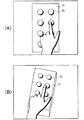
以上述べたように、第1の実施の形態では、操作部2を基準としてカメラ3の位置データΘ1と操作者視点の位置データΘ2,Φ2とをあらかじめ位置情報記憶装置5に記憶させておき、位置データΘ1と位置データΘ2,Φ2との関係に基づいて、画像処理装置6にてカメラ3が取得した画像を操作者の視点から見た画像に変換処理し、これをディスプレイ装置4に表示できる。この際に得られる画像例を図4に示す。図4の(A)はカメラ3が取得したままの画像を示している。この画像は操作部2をかなり斜め上方から取得しているため、操作部2が縦方向につぶれており、操作ボタン2a同士の上下の間隔は狭く、本来は円形である操作ボタン2aの形状は歪んだ楕円となっている。これに対して図4の(B)は視点を移動させて画像変換処理を行った後の画像であり、ここでは操作者が実際に見る形状に近く、立体感が出ている。このような第1の実施の形態によれば、ディスプレイ装置4の画像を見ながら操作部2を操作する際、操作者は違和感を感じずに済む。したがって、使い勝手が良く、スムーズな操作を実感でき、操作性が大きく向上する。
【0022】
(2)第2の実施の形態…請求項2および3に対応
[構成]
続いて、請求項2および3の発明に対応する第2の実施の形態について図5〜図8を参照して説明する。図5は第2の実施の形態のブロック図、図6は第2の実施の形態における構成要素の配置を示す斜視図、図7は第2の実施の形態において操作部2を基準点としてカメラ3の位置と操作者の視点位置とを示す模式図、図8は第2の実施の形態における画像例を示している。
【0023】
図5に示すように、第2の実施の形態に係る車載用情報機器において、操作部2はメニュー項目に対応して複数の操作ボタンからなるスイッチマトリックス21から構成されている。スイッチマトリックス21は制御装置7によってメニュー項目に応じて必要なものだけが凸状態となり不必要なものは平坦状態となるように制御されている。また、図6に示すように、第2の実施の形態ではこのようなスイッチマトリックス21が操作者の左側にほぼ水平に設置されている。このため、カメラ3はスイッチマトリックス21の画像をほぼ真上から取得するようになっており、カメラ3の位置データΘ1はかなり小さい値となる(図7参照)。さらに、第2の実施の形態ではディスプレイ装置4において、スイッチマトリックス21の画像とメニュー項目とが一致して表示されるようになっている。
【0024】
[作用効果]
以上のような第2の実施の形態では、前記第1の実施の形態と同様に、あらかじめ位置情報記憶装置5に記憶させたカメラ3の位置データΘ1と操作者視点の位置データΘ2,Φ2の関係から、画像処理装置6にてカメラ3が取得した画像を操作者の視点から見た画像に変換処理し、これをディスプレイ装置4に表示できる。この際に得られる画像例を図8に示す。図8の(A)はカメラ3が取得したままの画像を示している。この画像では水平状態のスイッチマトリックス21をほぼ真上から映しているため、操作ボタン2aは立体感の無い円形となっており、平面的である。したがって、操作ボタン2aが凸状態のものと平坦なものとに分かれていても、図8の(A)の画像からこれらを区別することは困難である。これに対して図8の(B)は視点を移動させて画像変換後の画像であり、操作ボタン2aは楕円状となって立体感があり、操作者が実際に見える感じに近づけることができる。
【0025】
したがって、第2の実施の形態によれば、メニュー項目に応じて凸状態となるスイッチマトリックス21を的確に表示することができる。これにより、ディスプレイ装置4で画像を見ている感覚と、実際にスイッチマトリックス21を触っている操作感覚との間に、意識の上でギャップがなく、表示手段の画像を見ながらでも正確な操作を行うことができる。しかも、第2の実施の形態においては、操作ボタン2aの画像とメニュー項目とがディスプレイ装置4上で一致しているため、操作状況を容易に把握でき、操作性のさらなる向上を図ることができる。
【0026】
(3)第3の実施の形態…請求項4に対応
[構成]
第3の実施の形態は請求項4の発明に対応しており、図9は第3の実施の形態のブロック図、図10は第3の実施の形態におけるフローチャート、図11は第3の実施の形態における画像例を示している。なお、第3の実施の形態における操作部2、カメラ3およびディスプレイ装置4の配置構成は前記第2の実施の形態と同じである。
【0027】
図9に示すように、第3の実施の形態は、前記第2の実施の形態の構成要素に加えて、手画像切り出し装置8、立体メニュー生成記憶装置9、画像合成装置10を備えた点に特徴がある。手画像切り出し装置8は画像処理装置6に接続されており、画像処理装置6が変換した画像の中から操作者の手の画像のみを切り出すように構成されている。
【0028】
また、立体メニュー生成記憶装置9は車載用情報機器のメニュー項目に対応させて立体的なメニューボタンの画像を生成、記憶するようにようになっている。画像合成装置10は前記手画像切り出し装置8および立体メニュー生成記憶装置9に接続され、両者からそれぞれ、操作者の手の画像および立体的なメニューボタンの画像とを取り込み合成させるものである。
【0029】
[作用効果]
第3の実施の形態が画像を表示するまでの作業について、図10のフローチャートに沿って説明する。まず、スイッチマトリックス21を操作する操作者の手の画像をカメラ3が取得する(S201)。続いて、カメラ3の位置情報Θ1と操作者視点のΘ2,Φ2の関係から、画像処理装置6にてカメラ3が取得した画像を操作者の視点から見た画像に変換処理する(S202)。次に、手画像切り出し装置8が画像処理装置6が変換した画像の中から操作者の手の画像のみを切り出す(S203)。一方、立体メニュー生成記憶装置9ではメニューボタンの画像を生成し(S204)、これを立体化処理する(S205)。
【0030】
画像合成装置10では手画像切り出し装置8が切り出した操作者の手の画像と、立体メニュー生成記憶装置9が生成した立体的なメニューボタンの画像とを取り込む。そして、立体的なメニューボタンの画像に操作者の手の画像を貼り付けるようにして両者を合成させ、1つの画像とする(S206)。最終的に、合成画像をディスプレイ装置4が表示する(S207)。に送るこの画像に操作者の手の画像だけを貼り付けて表示することができる。
【0031】
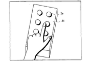
このときの合成画像例を図11に示す。この図に示した画像例は、図8の(B)にて示した前記第2の実施の形態における視点変換処理後の画像例よりも、さらに立体感を引き出すことに成功している。これは、カメラ3が取得する画像が図8の(A)に示したように非常な平面的である場合、奥行き方向の画像データが少ないため、画像処理装置6にて視点変換の処理を行ったとしても立体感を引き出すには限界があるためである。
【0032】
また、カメラ3がスイッチマトリックス21の画像を取得する際、操作者の手によって一部が隠れてしまえば、いくら画像処理装置6にて画像処理を行ったにせよ、もともとの画像データが不足することになる。そのため、取得していない部分の画像に関しては表示することができず、画像の表示が虫食い状態となる可能性がある。この場合には、操作している感覚とディスプレイ装置4に表示された画像を見ている感覚との間に大きなギャップが生じることになる。
【0033】
このような不具合に対して上記第3の実施の形態は有効である。すなわち、立体的なメニューボタンの画像を生成しておき、この画像と実際に操作している操作者の手の画像とを合成させることで、操作状況を把握できる視認性の高い仮想的な画像を得ることができる。したがって、カメラ3が取得する画像が平面的であったり、不完全であったとしても、表示画像を、操作者が実際に操作部を見た感じに近付けることができ、優れた操作性を確保することができる。また、カメラ3が取得しなくてはならない画像としては、最低限、操作者の手の画像を得る事ができれば良い。このため、カメラ3の取付位置は自由度が高くなり、狭い車両スペースから受ける制約を緩和することができる。
【0034】
(4)他の実施の形態
本発明は以上の実施の形態に限定されるものではなく、操作部のスイッチ構成や表示手段の取付位置などは適宜選択可能であり、車載用情報機器としては音響機器だけではなくナビゲーション装置などにも適用可能である。さらに、第1の実施の形態において、第3の実施の形態に示したような立体的なメニューボタンの画像と操作者の手の画像とを合成させる構成を採用しても良い。
【0035】
また、請求項5の発明に対応する実施の形態として、操作者視点に関する位置情報の設定を変更する機能を有するものも包含する。このような実施の形態によれば、操作者が交替して視点の位置が変わったとしても、操作者視点に関する位置情報の設定を随時変更することができる。そのため、操作者ごとに視点の位置情報を設定可能である。これにより、きめ細かな画像変換処理を実施することができ、いかなる操作者に対しても優れた操作性を発揮することができる。
【0036】
なお、ここでいう操作者の視点位置とは、操作者から操作部が実際に見える時の視点位置を意味しており、カメラからの取得画像を、操作部が見えないような位置からの画像に変換処理しても何の意味もない。具体的には、図12にて示した操作部2を直接見る場合の視界Bでは、水平な操作部2をほぼ真横から見るような状況となるため、カメラ3が取得した画像をこの視界Bから見たことに相当する画像に変換しても、見えにくい画像に変換されるだけである。
【0037】
このような実施の形態では操作部2が実際に見える視点位置を選定することが重要であって、図13に示すように、操作部2が実際に見える時の仮想的な操作者視点を位置Θ2,Φ2とし、この視点から見た画像に変換する必要がある。この実施の形態においても、前記第1〜第3の実施の形態と同様、あらかじめ位置情報記憶装置5に記憶させたカメラ3の位置データΘ1と操作者視点の位置データΘ2,Φ2の関係から、画像処理装置6にてカメラ3が取得した画像を操作者の視点から見た画像に変換処理し、これをディスプレイ装置4に表示する。この際に得られる画像例を図14に示す。図14の(A)はカメラ3が取得したままの画像を示している。この画像では水平状態の操作部2を真上から映しているため、先に示した図8の(A)の画像と同様、操作ボタン2aは立体感の無い円形となっており、平面的である。これに対して画像変換を処理した後の画像である図14の(B)は、操作ボタン2aは楕円状となっており、操作者が実際に見える感じに近づけることができる。
【0038】
【発明の効果】
以上説明したように、本発明によれば、画像取得手段が取得した画像を、操作者視点から見た画像に変換し、これを表示手段に表示することにより、表示示された画像を操作者が実際に見た場合の操作部に近けることがことができ、表示された画像を見ながら優れた操作性を発揮でき、安全性の向上に寄与する車載用情報機器を提供することができる。
【図面の簡単な説明】
【図1】本発明に係る第1の実施の形態のブロック図。
【図2】第1の実施の形態において操作部2を基準点としてカメラ3の位置と操作者の視点位置とを示す模式図。
【図3】第1の実施の形態の要部における作業のフローチャート。
【図4】第1の実施の形態における画像例であり、(A)はカメラ3が取得したままの画像、(B)は画像変換処理を行った後の画像を示す。
【図5】本発明に係る第2の実施の形態のブロック図。
【図6】第2の実施の形態における構成要素の配置を示す斜視図。
【図7】第2の実施の形態において操作部2を基準点としてカメラ3の位置と操作者の視点位置とを示す模式図。
【図8】第2の実施の形態における画像例であり、(A)はカメラ3が取得したままの画像、(B)は画像変換処理を行った後の画像を示す。
【図9】本発明に係る第3の実施の形態のブロック図。
【図10】第3の実施の形態におけるフローチャート。
【図11】第3の実施の形態において画像変換処理を行った後の画像例。
【図12】本発明に係る他の実施の形態における構成要素の配置を示す斜視図。
【図13】図12に示した他の実施の形態において操作部2を基準点としてカメラ3の位置と操作者の視点位置とを示す模式図。
【図14】図12に示した他の実施の形態においてける画像例であり、(A)はカメラ3が取得したままの画像、(B)は画像変換処理を行った後の画像を示す。
【図15】従来の車載用情報機器における構成要素の配置を示す斜視図。
【図16】操作者が実際に手を動かしている向きと、ディスプレイ装置上で表示される手の動きの向きと、操作者が実感として感じる手の動きの向きとを示す説明図。
【符号の説明】
1…機器本体
2…操作部
2a…操作ボタン
3…カメラ
4…ディスプレイ装置
5…位置情報記憶装置
6…画像処理装置
7…制御装置
8…手画像切り出し装置
9…立体メニュー生成記憶装置
10…画像合成装置
21…スイッチマトリックス
Θ1…カメラの位置データ
Θ2,Φ2…操作者視点の位置データ[0001]
BACKGROUND OF THE INVENTION
The present invention relates to an in-vehicle information device that displays an image of an operation unit on a display unit and operates the operation unit while viewing the image.
[0002]
[Prior art]
Generally, a panel-like operation unit having a plurality of buttons and volumes is arranged in an in-vehicle device. When operating the operation unit, the operator reaches the position of the button or volume while confirming the position of the button or volume with a line of sight, and selects the target button or volume. When the operator who performs the above operations is driving the vehicle, the operator must keep his / her line of sight ahead and must maintain a stable driving posture as much as possible. For this reason, it is desirable that the mounting position of the operation portion be inside the region that is naturally visible when the operator is driving (hereinafter referred to as the driving field of view).
[0003]
However, there are restrictions on the space of the vehicle, and it is substantially difficult to attach the operation unit within the driving field of view. Therefore, the operation unit must be attached at a position slightly deviated from the driving field of view. Therefore, in a state where the operator holds the line of sight forward, the operation unit is often operated by groping, and the operability is low. Regarding the operability of in-vehicle devices, a very high level is required from the viewpoint of safety. Therefore, conventionally, an in-vehicle information device has been proposed in which a display device is attached in the driving field of view and an image of an operation unit is displayed on the display device.
[0004]
A conventional example of such an in-vehicle information device will be described with reference to FIG. When it is assumed that the driver of the right-hand drive vehicle is an operator, the device main body 1 and the
[0005]
According to the in-vehicle information device having the above configuration, an operation can be performed while viewing the image of the
[0006]
[Problems to be solved by the invention]
However, the above prior art has the following problems. That is, the
[0007]
For this reason, depending on the position of the
[0008]
The disagreement between the position of the
[0009]
The present invention has been proposed in order to solve such a problem, and the object is to display an image corresponding to a case where the operator directly views the operation unit on the display unit. An object of the present invention is to provide an in-vehicle information device that can eliminate the uncomfortable feeling at the time of operation received from the above image, can exhibit excellent operability while viewing the displayed image, and contributes to improvement in safety.
[0010]
[Means for Solving the Problems]
In order to achieve the above object, the present invention provides an in-vehicle device in which an operation unit that operates an in-vehicle device, an image acquisition unit that acquires an image of the operation unit, and a display unit that displays an image of the operation unit are arranged. The information equipment for use has the following structural features.
[0011]
According to the first aspect of the present invention, position information storage means for storing in advance position information of the image acquisition means with respect to the operation section and position information of an operator viewpoint with respect to the operation section, and 2 stored in the position information storage means. Image processing means for converting an image acquired by the image acquisition means into an image viewed from the viewpoint of the operator based on one position information, and the display means is an image converted by the image processing means. It is characterized by being configured to display.
In the first aspect of the invention having the above-described configuration, the position information storage means stores in advance the position information of the image acquisition means and the operator's viewpoint with reference to the operation section. Based on these two pieces of position information, the image processing means converts the image acquired by the image acquisition means into an image viewed from the operator's viewpoint, and displays this on the display means. For this reason, the image displayed on the display means is close to the operation unit when the operator actually sees it, and the shape and stereoscopic effect of the operation unit are not impaired. Therefore, even if the operation is performed while viewing the image on the display means, the operator does not feel uncomfortable, and excellent operability can be obtained.
[0012]
According to a second aspect of the present invention, in the in-vehicle information device according to the first aspect, a plurality of operation buttons are arranged in the operation unit corresponding to the menu items of the in-vehicle information device, and the operation buttons are in-vehicle information. Only necessary items are in a convex state according to the menu items of the device, and unnecessary items are in a flat state.
In the above invention of
[0013]
According to a third aspect of the present invention, in the in-vehicle information device according to the first or second aspect, the operation unit includes a plurality of operation buttons corresponding to menu items of the in-vehicle information device, and the display means The operation button image and the menu item are displayed so as to coincide with each other.
In the invention of
[0014]
According to a fourth aspect of the present invention, in the in-vehicle information device according to any one of the first to third aspects, when the image acquisition unit acquires an image of a hand of an operator who operates the operation unit, the image processing unit A hand image cutout unit that cuts out only the image of the operator's hand from the converted image, and a menu button image generation unit that generates a three-dimensional menu button image corresponding to the menu item of the in-vehicle information device. And an image compositing means for compositing the image of the operator's hand cut out by the hand image cut-out means and the three-dimensional menu button image generated by the menu button image generating means, and the display means It is characterized in that it is configured to display an image synthesized by the image synthesizing means.
In the invention of
[0015]
According to a fifth aspect of the present invention, in the in-vehicle information device according to any one of the first to fourth aspects, a viewpoint position information setting changing unit for changing a setting of position information related to an operator viewpoint is provided. It is said.
In such a fifth aspect of the invention, even when the position of the viewpoint changes due to the change of the operator, the image conversion processing according to the viewpoint of each operator is performed by changing the setting of the position information regarding the operator viewpoint. Is possible. Therefore, excellent operability can be exhibited for any operator.
[0016]
DETAILED DESCRIPTION OF THE INVENTION
Hereinafter, an example of an embodiment of the present invention will be specifically described with reference to the drawings. All of the following embodiments are applied to in-vehicle information equipment mainly composed of audio equipment including in-vehicle CD players. The same members as those in the conventional example shown in FIG.
[0017]
(1) First embodiment ... corresponding to claim 1
[Constitution]
The first embodiment corresponds to the invention of claim 1. FIG. 1 is a block diagram of the first embodiment, FIG. 2 is a schematic diagram showing the position of the
[0018]
As shown in FIG. 1, the in-vehicle information device according to the first embodiment includes a device main body 1, an
[0019]
The feature of the first embodiment is that a position
[0020]
[Function and effect]
A series of operations in the position
[0021]
As described above, in the first embodiment, the position data Θ1 of the
[0022]
(2) Second embodiment ... corresponding to
[Constitution]
Next, a second embodiment corresponding to the second and third aspects of the invention will be described with reference to FIGS. FIG. 5 is a block diagram of the second embodiment, FIG. 6 is a perspective view showing the arrangement of components in the second embodiment, and FIG. 7 is a camera with the
[0023]
As shown in FIG. 5, in the in-vehicle information device according to the second embodiment, the
[0024]
[Function and effect]
In the second embodiment as described above, as in the first embodiment, the position data Θ1 of the
[0025]
Therefore, according to the second embodiment, it is possible to accurately display the
[0026]
(3) Third embodiment ... corresponding to claim 4
[Constitution]
The third embodiment corresponds to the invention of
[0027]
As shown in FIG. 9, the third embodiment includes a hand image segmentation device 8, a three-dimensional menu generation storage device 9, and an image composition device 10 in addition to the components of the second embodiment. There is a feature. The hand image cutout device 8 is connected to the
[0028]
The three-dimensional menu generation / storage device 9 generates and stores a three-dimensional menu button image corresponding to the menu item of the in-vehicle information device. The image composition device 10 is connected to the hand image cutout device 8 and the three-dimensional menu generation / storage device 9, and captures and synthesizes the image of the operator's hand and the image of the three-dimensional menu button, respectively.
[0029]
[Function and effect]
Operations until the third embodiment displays an image will be described with reference to the flowchart of FIG. First, the
[0030]
The image composition device 10 captures the image of the operator's hand cut out by the hand image cutout device 8 and the image of the three-dimensional menu button generated by the three-dimensional menu generation storage device 9. Then, both images are synthesized by pasting the image of the operator's hand on the image of the three-dimensional menu button to form one image (S206). Finally, the
[0031]
An example of the composite image at this time is shown in FIG. The image example shown in this figure has succeeded in extracting a stereoscopic effect further than the image example after the viewpoint conversion processing in the second embodiment shown in FIG. 8B. This is because when the image acquired by the
[0032]
Further, when the
[0033]
The third embodiment is effective for such a problem. In other words, a highly visible virtual image that can grasp the operation status by generating a three-dimensional menu button image and combining this image with the image of the hand of the operator who is actually operating. Can be obtained. Therefore, even if the image acquired by the
[0034]
(4) Other embodiments
The present invention is not limited to the above-described embodiment, and the switch configuration of the operation unit, the mounting position of the display means, and the like can be selected as appropriate. Is also applicable. Furthermore, in the first embodiment, a configuration in which the three-dimensional menu button image and the operator's hand image as shown in the third embodiment may be employed.
[0035]
Further, an embodiment corresponding to the invention of
[0036]
The viewpoint position of the operator here means the viewpoint position when the operation unit is actually seen by the operator, and the acquired image from the camera is an image from a position where the operation unit cannot be seen. There is no point in converting to. Specifically, in the field of view B when directly viewing the
[0037]
In such an embodiment, it is important to select a viewpoint position at which the
[0038]
【The invention's effect】
As described above, according to the present invention, the image acquired by the image acquisition unit is converted into an image viewed from the operator's viewpoint, and this is displayed on the display unit. Can be close to the operation section when actually viewed, can exhibit excellent operability while viewing the displayed image, and can provide an in-vehicle information device that contributes to improving safety .
[Brief description of the drawings]
FIG. 1 is a block diagram of a first embodiment according to the present invention.
FIG. 2 is a schematic diagram showing the position of the
FIG. 3 is a flowchart of work in a main part of the first embodiment.
4A and 4B are image examples in the first embodiment, where FIG. 4A shows an image as acquired by the
FIG. 5 is a block diagram of a second embodiment according to the present invention.
FIG. 6 is a perspective view showing the arrangement of components in the second embodiment.
7 is a schematic diagram showing the position of the
8A and 8B are examples of images according to the second embodiment, where FIG. 8A shows an image as acquired by the
FIG. 9 is a block diagram of a third embodiment according to the present invention.
FIG. 10 is a flowchart according to the third embodiment.
FIG. 11 shows an example of an image after performing image conversion processing in the third embodiment.
FIG. 12 is a perspective view showing the arrangement of components in another embodiment according to the present invention.
13 is a schematic diagram showing the position of the
14A and 14B are examples of images in the other embodiment shown in FIG. 12, in which FIG. 14A shows an image as acquired by the
FIG. 15 is a perspective view showing the arrangement of components in a conventional in-vehicle information device.
FIG. 16 is an explanatory diagram showing the direction in which the operator actually moves the hand, the direction of the hand movement displayed on the display device, and the direction of the hand movement that the operator feels as a real feeling.
[Explanation of symbols]
1 ... Main unit
2 ... Operation part
2a ... Operation buttons
3 ... Camera
4. Display device
5. Position information storage device
6. Image processing apparatus
7. Control device
8 ... Hand image clipping device
9 ... Three-dimensional menu generation storage device
10: Image composition device
21 ... Switch matrix
Θ1 ... Camera position data
Θ2, Φ2 ... Position data of the operator's viewpoint
Claims (5)
前記操作部に対する前記画像取得手段の位置情報および前記操作部に対する操作者視点の位置情報をあらかじめ記憶する位置情報記憶手段と、
前記位置情報記憶手段にて記憶された2つの位置情報に基づいて前記画像取得手段で取得した画像を操作者視点から見た画像に変換処理する画像処理手段とが設けられ、
前記表示手段は前記画像処理手段にて変換処理された画像を表示するように構成されたことを特徴とする車載用情報機器。In an in-vehicle information device in which an operation unit that operates an in-vehicle device, an image acquisition unit that acquires an image of the operation unit, and a display unit that displays an image of the operation unit are arranged.
Position information storage means for storing in advance position information of the image acquisition means with respect to the operation section and position information of an operator viewpoint with respect to the operation section;
Image processing means for converting the image acquired by the image acquisition means into an image viewed from the viewpoint of the operator based on the two pieces of position information stored in the position information storage means,
The in-vehicle information device characterized in that the display means is configured to display an image converted by the image processing means.
前記操作ボタンは車載用情報機器のメニュー項目に応じて必要なものだけが凸状態となり、不必要なものは平坦状態となるように構成されたことを特徴とする請求項1に記載の車載用情報機器。In the operation unit, a plurality of operation buttons are arranged corresponding to the menu items of the in-vehicle information device,
2. The vehicle-mounted device according to claim 1, wherein the operation buttons are configured such that only necessary ones are convex according to menu items of the on-vehicle information device, and unnecessary ones are flat. Information equipment.
前記表示手段は前記操作ボタンの画像と前記メニュー項目を一致させて表示するように構成されたことを特徴とする請求項1または2に記載の車載用情報機器。In the operation unit, a plurality of operation buttons are arranged corresponding to the menu items of the in-vehicle information device,
The in-vehicle information device according to claim 1, wherein the display unit is configured to display the operation button image and the menu item so as to coincide with each other.
車載用情報機器のメニュー項目に対応させて立体的なメニューボタンの画像を生成するメニューボタン画像生成手段と、
前記手画像切り出し手段が切り出した操作者の手の画像と、前記メニューボタン画像生成手段が生成した立体的なメニューボタンの画像とを合成させる画像合成手段とが設けられ、
前記表示手段は前記画像合成手段にて合成された画像を表示するように構成されたことを特徴とする請求項1〜3のいずれか一項に記載の車載用情報機器。When the image acquisition means acquires an image of an operator's hand operating the operation unit, a hand image cutout means for cutting out only the image of the operator's hand from the image converted by the image processing means;
Menu button image generation means for generating a three-dimensional menu button image corresponding to the menu item of the in-vehicle information device;
Image combining means for combining the image of the operator's hand cut out by the hand image cutout means and the three-dimensional menu button image generated by the menu button image generation means is provided;
The in-vehicle information device according to claim 1, wherein the display unit is configured to display an image synthesized by the image synthesis unit.
Priority Applications (1)
| Application Number | Priority Date | Filing Date | Title |
|---|---|---|---|
| JP2001338549A JP4769397B2 (en) | 2001-09-28 | 2001-09-28 | In-vehicle information equipment |
Applications Claiming Priority (1)
| Application Number | Priority Date | Filing Date | Title |
|---|---|---|---|
| JP2001338549A JP4769397B2 (en) | 2001-09-28 | 2001-09-28 | In-vehicle information equipment |
Publications (2)
| Publication Number | Publication Date |
|---|---|
| JP2003104122A JP2003104122A (en) | 2003-04-09 |
| JP4769397B2 true JP4769397B2 (en) | 2011-09-07 |
Family
ID=19153023
Family Applications (1)
| Application Number | Title | Priority Date | Filing Date |
|---|---|---|---|
| JP2001338549A Expired - Fee Related JP4769397B2 (en) | 2001-09-28 | 2001-09-28 | In-vehicle information equipment |
Country Status (1)
| Country | Link |
|---|---|
| JP (1) | JP4769397B2 (en) |
Families Citing this family (8)
| Publication number | Priority date | Publication date | Assignee | Title |
|---|---|---|---|---|
| JP2004334590A (en) * | 2003-05-08 | 2004-11-25 | Denso Corp | Operation input device |
| JP4389855B2 (en) | 2005-09-05 | 2009-12-24 | トヨタ自動車株式会社 | Vehicle control device |
| JP2007156950A (en) * | 2005-12-07 | 2007-06-21 | Toyota Motor Corp | Vehicle operating device |
| JP4797752B2 (en) | 2006-03-31 | 2011-10-19 | 株式会社デンソー | Operating object extraction device for moving objects |
| US8094189B2 (en) | 2007-01-30 | 2012-01-10 | Toyota Jidosha Kabushiki Kaisha | Operating device |
| JP4356763B2 (en) * | 2007-01-30 | 2009-11-04 | トヨタ自動車株式会社 | Operating device |
| DE102008023405B4 (en) * | 2008-05-13 | 2020-10-01 | Volkswagen Ag | Motor vehicle with a display and method for operating a motor vehicle with a display |
| JP5240277B2 (en) * | 2010-11-05 | 2013-07-17 | トヨタ自動車株式会社 | In-vehicle remote control device |
Family Cites Families (5)
| Publication number | Priority date | Publication date | Assignee | Title |
|---|---|---|---|---|
| JPH10269012A (en) * | 1997-03-28 | 1998-10-09 | Yazaki Corp | Touch panel controller and information display device using the same |
| JP2000006687A (en) * | 1998-06-25 | 2000-01-11 | Yazaki Corp | Onboard equipment switch safety operation system |
| JP2000335330A (en) * | 1999-05-27 | 2000-12-05 | Clarion Co Ltd | On-board switch operating device |
| JP3298851B2 (en) * | 1999-08-18 | 2002-07-08 | 松下電器産業株式会社 | Multi-function vehicle camera system and image display method of multi-function vehicle camera |
| JP3301421B2 (en) * | 1999-10-20 | 2002-07-15 | 松下電器産業株式会社 | Vehicle surrounding situation presentation device |
-
2001
- 2001-09-28 JP JP2001338549A patent/JP4769397B2/en not_active Expired - Fee Related
Also Published As
| Publication number | Publication date |
|---|---|
| JP2003104122A (en) | 2003-04-09 |
Similar Documents
| Publication | Publication Date | Title |
|---|---|---|
| JP5110438B2 (en) | Input device | |
| CA2730379C (en) | Vehicle user interface unit for a vehicle electronic device | |
| JP4356763B2 (en) | Operating device | |
| JP4251673B2 (en) | Image presentation device | |
| EP1742489B1 (en) | Image display device and graphic processor for stereoscopic display of 3D graphic objects | |
| US8094189B2 (en) | Operating device | |
| JP4537537B2 (en) | Driving assistance device | |
| JP2007042073A (en) | Video presentation system, video presentation method, program for causing computer to execute video presentation method and storage medium | |
| JP5814532B2 (en) | Display control program, display control apparatus, display control system, and display control method | |
| JP4413203B2 (en) | Image presentation device | |
| JP4769397B2 (en) | In-vehicle information equipment | |
| JPH07311857A (en) | Picture compositing and display device and simulation system | |
| JP2012065066A (en) | Stereoscopic image generation device, stereoscopic image display device, stereoscopic image adjustment method, program for allowing computer to perform stereoscopic image adjustment method, and recording medium with program recorded therein | |
| JPWO2012053033A1 (en) | 3D stereoscopic display device and 3D stereoscopic display processing device | |
| JP2014069629A (en) | Image processor, and image processing system | |
| JP6257978B2 (en) | Image generation apparatus, image display system, and image generation method | |
| WO2005017729A2 (en) | Interface method and device between man and machine realised by manipulating virtual objects | |
| CN113221381B (en) | Design method of virtual reality multi-view fusion model | |
| JP5465334B2 (en) | 3D stereoscopic display device | |
| JP2004178581A (en) | Image generation system, image generation method, program, and information storage medium | |
| JP2009519481A (en) | Observation system for manipulating objects | |
| JP4757132B2 (en) | Data input device | |
| JP3640256B2 (en) | Method for producing stereoscopic printed matter, stereoscopic printed matter | |
| JP4133356B2 (en) | Image composition apparatus, composition method, and program for realizing the method | |
| JP5085722B2 (en) | Image generation system |
Legal Events
| Date | Code | Title | Description |
|---|---|---|---|
| A621 | Written request for application examination |
Free format text: JAPANESE INTERMEDIATE CODE: A621 Effective date: 20080919 |
|
| A977 | Report on retrieval |
Free format text: JAPANESE INTERMEDIATE CODE: A971007 Effective date: 20110330 |
|
| A01 | Written decision to grant a patent or to grant a registration (utility model) |
Free format text: JAPANESE INTERMEDIATE CODE: A01 Effective date: 20110531 |
|
| A01 | Written decision to grant a patent or to grant a registration (utility model) |
Free format text: JAPANESE INTERMEDIATE CODE: A01 |
|
| A61 | First payment of annual fees (during grant procedure) |
Free format text: JAPANESE INTERMEDIATE CODE: A61 Effective date: 20110620 |
|
| R150 | Certificate of patent or registration of utility model |
Free format text: JAPANESE INTERMEDIATE CODE: R150 |
|
| FPAY | Renewal fee payment (event date is renewal date of database) |
Free format text: PAYMENT UNTIL: 20140624 Year of fee payment: 3 |
|
| R250 | Receipt of annual fees |
Free format text: JAPANESE INTERMEDIATE CODE: R250 |
|
| R250 | Receipt of annual fees |
Free format text: JAPANESE INTERMEDIATE CODE: R250 |
|
| R250 | Receipt of annual fees |
Free format text: JAPANESE INTERMEDIATE CODE: R250 |
|
| LAPS | Cancellation because of no payment of annual fees |