JP4763791B2 - Optimized synchronization of MAC address tables in network interconnect devices - Google Patents
Optimized synchronization of MAC address tables in network interconnect devices Download PDFInfo
- Publication number
- JP4763791B2 JP4763791B2 JP2008530461A JP2008530461A JP4763791B2 JP 4763791 B2 JP4763791 B2 JP 4763791B2 JP 2008530461 A JP2008530461 A JP 2008530461A JP 2008530461 A JP2008530461 A JP 2008530461A JP 4763791 B2 JP4763791 B2 JP 4763791B2
- Authority
- JP
- Japan
- Prior art keywords
- interface port
- entry
- series
- card
- cards
- Prior art date
- Legal status (The legal status is an assumption and is not a legal conclusion. Google has not performed a legal analysis and makes no representation as to the accuracy of the status listed.)
- Expired - Fee Related
Links
- 238000000034 method Methods 0.000 claims description 16
- 230000000875 corresponding effect Effects 0.000 claims description 15
- 230000004044 response Effects 0.000 claims description 15
- 230000002596 correlated effect Effects 0.000 claims description 4
- 230000002123 temporal effect Effects 0.000 claims 2
- 238000004891 communication Methods 0.000 description 8
- 230000007246 mechanism Effects 0.000 description 6
- 230000008569 process Effects 0.000 description 6
- 230000005540 biological transmission Effects 0.000 description 4
- 238000010586 diagram Methods 0.000 description 3
- 230000009471 action Effects 0.000 description 2
- 230000008901 benefit Effects 0.000 description 2
- 230000014759 maintenance of location Effects 0.000 description 2
- 238000007726 management method Methods 0.000 description 2
- 238000005516 engineering process Methods 0.000 description 1
- 230000008450 motivation Effects 0.000 description 1
- 238000005457 optimization Methods 0.000 description 1
- 230000001360 synchronised effect Effects 0.000 description 1
- 239000002699 waste material Substances 0.000 description 1
Images


Classifications
-
- H—ELECTRICITY
- H04—ELECTRIC COMMUNICATION TECHNIQUE
- H04L—TRANSMISSION OF DIGITAL INFORMATION, e.g. TELEGRAPHIC COMMUNICATION
- H04L12/00—Data switching networks
- H04L12/28—Data switching networks characterised by path configuration, e.g. LAN [Local Area Networks] or WAN [Wide Area Networks]
- H04L12/46—Interconnection of networks
- H04L12/4604—LAN interconnection over a backbone network, e.g. Internet, Frame Relay
- H04L12/462—LAN interconnection over a bridge based backbone
- H04L12/4625—Single bridge functionality, e.g. connection of two networks over a single bridge
-
- H—ELECTRICITY
- H04—ELECTRIC COMMUNICATION TECHNIQUE
- H04L—TRANSMISSION OF DIGITAL INFORMATION, e.g. TELEGRAPHIC COMMUNICATION
- H04L45/00—Routing or path finding of packets in data switching networks
- H04L45/02—Topology update or discovery
Landscapes
- Engineering & Computer Science (AREA)
- Computer Networks & Wireless Communication (AREA)
- Signal Processing (AREA)
- Small-Scale Networks (AREA)
- Data Exchanges In Wide-Area Networks (AREA)
- Mobile Radio Communication Systems (AREA)
- Time-Division Multiplex Systems (AREA)
Abstract
Description
本発明は、特に、マルチポイント型の仮想プライベートLANサービスを供給するシステムにおいて、MACアドレステーブルの自動最適化同期を可能にする方法に関する。本発明はまた前記方法に従う装置も対象とするものである。 In particular, the present invention relates to a method that enables automatic optimization synchronization of a MAC address table in a system that provides a multipoint virtual private LAN service. The invention is also directed to an apparatus according to the method.
メトロポリタン(大都市)ネットワークはバーチャル(仮想)LANサービスのサポートという非常に重要な要件と共に発展している。マルチプロトコルラベル交換(MPLS)という文脈では、この仮想LANサービスとは、マルチポイント間の接続性によって一般に特徴づけられる仮想プライベートLANサービス(VPLS)サービスの提供を意味する。このLANサービスは、MPLSネットワークがクライアントによりスイッチ(交換装置)として知覚される必要があり、より単純なポイント間の接続性、すなわち仮想プライベート有線サービス(VPWS)に比べて、ネットワークアーキテクチャ並びにこのシステムにおける若干の複雑さを包含している。マルチポイント間の接続性においては、任意のユーザ位置は同じ仮想LAN上で他の任意の位置とトラフィックの交換を行うことができる。 Metropolitan networks are evolving with the very important requirement of supporting virtual LAN services. In the context of multi-protocol label exchange (MPLS), this virtual LAN service means the provision of a virtual private LAN service (VPLS) service that is generally characterized by multipoint connectivity. This LAN service requires that the MPLS network be perceived as a switch (switch) by the client, compared to a simpler point-to-point connectivity, ie Virtual Private Wired Service (VPWS), in the network architecture as well as in this system. Includes some complexity. In multipoint connectivity, any user location can exchange traffic with any other location on the same virtual LAN.
ユーザは個々の位置から2つ以上のポートを経由してVPLSに接続することができる。そして、一般に、前記ポート(物理インタフェース)はメトロポリタンネットワークシステムにおける各種トラフィックカードに属することができる。このメトロポリタンネットワークシステムは、その全体において特に解決の効率に関して生じ得るいくつかの問題をもたらす場合がある。 Users can connect to VPLS from more than one port via two or more ports. In general, the port (physical interface) can belong to various traffic cards in a metropolitan network system. This metropolitan network system may pose several problems that may arise in its entirety, particularly with regard to the efficiency of the solution.
クライアントカードは、いわゆる媒体アクセス制御(MAC)アドレステーブルを保持するものであり、このアドレステーブルには、ソースのMACアドレス、入力ポート、VLAN、及び、テーブルにおけるエントリの有効期間(エイジ)の参照などの別のフィールドに関する情報が含まれている。これらの情報は適当な時間の経過後、削除されるものと仮定されている。クライアントポートとラインポート間で、並びに、複数のクライアントポート間で完全な接続性が実現されなければならない。以下で明らかにされるように、一般にMACテーブルでは、エントリ自身の適当なフィールドに挿入される数字によって表されるエントリの「有効期間」に基づいて、エントリが削除されるという事実により問題が生じることになる。 The client card holds a so-called medium access control (MAC) address table. In this address table, the source MAC address, input port, VLAN, and the valid period (age) of the entry in the table are referenced. Contains information about another field. These information are assumed to be deleted after an appropriate time. Full connectivity must be realized between client ports and line ports, as well as between multiple client ports. As will become apparent below, the MAC table is generally problematic due to the fact that entries are deleted based on the “validity” of the entry represented by a number inserted in the appropriate field of the entry itself. It will be.
2枚のクライアントカードはそれぞれ、クライアント装置に接続された、一定数のインタフェース又は入出力を備えているものと仮定する。この時、MACのYYアドレスにより識別された遠隔地のクライアント装置が前記クライアントカードの1つの或る一定のポートを介してトラフィックを送信するものと仮定する。前記クライアントカードは(クライアント側とライン側双方の)すべての可能な宛先へトラフィックを送信する。というのは、クライアントカードには宛先についての正確な情報がない(まだ学習されていない)からである。この動作は「フラッディング」として周知のものである。 Assume that each of the two client cards has a certain number of interfaces or inputs and outputs connected to the client device. At this time, it is assumed that the remote client device identified by the YY address of the MAC transmits traffic through one certain port of the client card. The client card sends traffic to all possible destinations (both client side and line side). This is because the client card does not have accurate information about the destination (not yet learned). This operation is known as “flooding”.
第1のカードのMACアドレステーブルに一時的に記憶される情報であって、MACアドレス、VLANラベル、ポート番号、等々のようなデータを有する同じ情報が、別のクライアントカードへ送られる。第2のカードもそのMACテーブルの中にデータを一時的に記憶する。 The same information that is temporarily stored in the MAC address table of the first card and has data such as MAC address, VLAN label, port number, etc. is sent to another client card. The second card also temporarily stores data in its MAC table.
トラフィックは、MACアドレスZZから反対方向に、適当なラインカードを介して装置に到着し、それから、VPLSの一部を形成するすべてのクライアントカードへ送信される。このメカニズムに関するさらなる詳細について以下に示すことにする。 Traffic arrives at the device in the opposite direction from the MAC address ZZ via an appropriate line card and then sent to all client cards that form part of the VPLS. Further details regarding this mechanism will be given below.
クライアントカードから受信し、ラインから到着した情報は、次いで周知の「水平分割」原理を順守することを目的として、VPLサービスに関与する別のクライアントカードへ転送される。上記「水平分割」原理の目的はループを回避することである。上記情報は双方の顧客カードに備えられたMACアドレステーブルの中へ登録される。MACアドレステーブル内の(有効期間を秒で表現する)有効期間フィールドは自動的に更新される。 Information received from the client card and arriving from the line is then forwarded to another client card involved in the VPL service in order to adhere to the well-known “horizontal split” principle. The purpose of the “horizontal split” principle is to avoid loops. The above information is registered in a MAC address table provided on both customer cards. The validity period field (expressing the validity period in seconds) in the MAC address table is automatically updated.
時間の経過とともに、MACアドレスYYはそのままZZへ向かってトラフィックを送信するが、クライアントカード1は、そのMACアドレステーブルを更新しつづけ、フラッディングメカニズムをまったく必要とせず、クライアントカードから正しいラインカードへの単純な転送のみを必要とすることになり、クライアントカード2は上記接続に関する情報をクライアントカード1から受信しなくなる。というのは、クライアントカード2は上記の通信に直接関与するものではなく、したがってその有効期間フィールドは次第に増加するからである。従来技術では、最長の有効期間(一般的な数字は300秒)に達すると、クライアントカード2が備えるMACテーブルにおける対応するエントリは削除される。これに対して、たとえ、トラフィックを処理して、クライアントカード1からのみクライアントネットワークへ上記トラフィックを転送しなければならない場合であっても、反対方向にラインカードから到着するトラフィックは、VPLSに属するすべてのクライアントカードへ転送されてしまう(そうでない場合には、別のMACアドレステーブルを一時的に記憶して、ラインカードに保持することが望ましい)。というのは、システムが、この情報をクライアントカード1のMACアドレステーブルの中に保持しているからである。不都合なことに、クライアントカード2は、自己が備えるMACアドレステーブル内の関連付けられたエントリの期限が切れて当該エントリを削除してしまうため、もはや正しい関連付けを認知できない。したがって、クライアントカード2がとることができる唯一のアクションは、VPLSに関与するすべてのポートへ向かって(クライアントネットワークへ向かって)フラッディングを実現することだけである。これは、実在する動機を何等伴わずにクライアントネットワークのリソースを費やすトラフィックとなる。
As time passes, the MAC address YY sends traffic toward ZZ as it is, but the
従来技術でも、フラッディングが生じる必要性を少なくするためのいくつかの解決方法が提案されている。 In the prior art, several solutions have been proposed to reduce the need for flooding.
第1の解決方法は、MACアドレステーブルをラインカードにも一時的に記憶することを必要とする解決方法である。したがって、ラインカードは、サポートしている個々のVPLSについてのMACアドレステーブルを完全に保持することを要求される。しかしながら、この解決方法は、複雑な処理及び重要なリソースの不必要な使用を伴うものとなる。 The first solution is a solution that requires that the MAC address table is also temporarily stored in the line card. Therefore, the line card is required to maintain a complete MAC address table for each supported VPLS. However, this solution involves complex processing and unnecessary use of critical resources.
第2の解決方法は、複数のユーザカード内における各MACアドレステーブルの完全かつ連続した同期を必要とする方法である。この解決方法の場合、すべての(通常3以上の)クライアントカードに存在するMACアドレステーブルを完全に同期する必要があり、その場合、MACアドレステーブルはいつでも同じ情報を含んでいなければならなくなる。このことはすべてのクライアントカード間での通信量の大幅な増加を伴うことになり、極めて重くかつ危機的な状態を招くことになる。 The second solution is a method that requires complete and continuous synchronization of each MAC address table in a plurality of user cards. For this solution, it is necessary to fully synchronize the MAC address tables present on all (typically three or more) client cards, in which case the MAC address tables must always contain the same information. This is accompanied by a significant increase in the amount of communication between all client cards, which leads to a very heavy and critical situation.
本発明の一般的な目的は、上記テーブルのための最適化された同期機構によって不要なフラッディング問題を回避することにより上述の欠点を改善することである。この同期機構はクライアントカードが備えるMACアドレステーブルを同期するために制御情報を送信する必要性を著しく減らすものとなる。 The general object of the present invention is to remedy the above-mentioned drawbacks by avoiding unnecessary flooding problems with an optimized synchronization mechanism for the table. This synchronization mechanism significantly reduces the need to send control information to synchronize the MAC address table provided in the client card.
上記目的に照らして、ネットワークの相互接続(インターコネクション)用インタフェースポートを備えたシステムにおけるMACアドレステーブルの管理方法を本発明に従って提供する方法が探求された。上記システムは、第1の一連のインタフェースポートカード及び第2の一連のインタフェースポートカードと、少なくとも第1及び第2の一連のカードとの間に、並びに、第1の一連のインタフェースポートカードとの間に相互接続用の相互接続ユニットとを備え、上記相互接続ユニットを経由して上記ポート間のトラフィックのアドレス指定を行うためのMACアドレステーブルが上記第1の一連のインタフェースポートカードに関連づけられて存在し、上記テーブルの個々のエントリは、上記エントリの有効期間を適時に定義するための関連付けられた有効期間フィールドを有し、上記管理方法は、上記エントリの有効期間フィールドが予め設定された最長有効期間の数字に達したかどうかを確認するステップと、前記最長有効期間の数字に達すると、上記第1の一連のインタフェースポートに属した別のカードに関連づけられ、かつ、更新対象の上記エントリ内の情報によって該別のカードと相関づけられて、上記テーブル内の対応するエントリの有効期間フィールドの中に含まれている上記数字に応じて前記エントリを更新するステップとを備える。 In light of the above objects, a method for providing a MAC address table management method according to the present invention in a system having an interface port for network interconnection has been sought. The system includes a first series of interface port cards and a second series of interface port cards, at least between the first and second series of cards, and with the first series of interface port cards. A MAC address table for addressing traffic between the ports via the interconnection unit and associated with the first series of interface port cards. Each entry of the table has an associated validity period field for defining the validity period of the entry in a timely manner, and the management method is the longest preset validity period field of the entry. A step of checking whether the number of validity period has been reached, and the number of the longest validity period The corresponding entry in the table is associated with another card belonging to the first series of interface ports and correlated with the other card by the information in the entry to be updated. Updating the entry according to the number contained in the validity period field.
また、本発明に従って、ネットワーク相互接続用のインタフェースポートを有するプラットフォームを備えたネットワーク相互接続装置の実現が探求された。該相互接続装置は、順に、第1と第2の一連のインタフェースポートカードと、少なくとも第1及び第2の一連のインタフェースポートカードとの間に、並びに、第1の一連のインタフェースポートカードとの間に、命令を受ける相互接続用の相互接続ユニットを備え、相互接続ユニットを経由するポート間のトラフィックをアドレス指定するためのMACアドレステーブルが、第1の一連のインタフェースポートカードに関連づけられて保持され、上記テーブルの個々のエントリは、エントリの有効期間を適時定義する、関連付けられた有効期間フィールドを有し、そして、上記ネットワーク相互接続装置は、エントリの有効期間フィールドが、予め設定された最高有効期間の数字に達したかどうかを定期的に確認し、次いで、前記最大の数字の着信時に、第1の一連の別のインタフェースポートカードへ同期要求を送信し、そして上記相互接続装置は、上記更新対象のエントリ内の情報によって上記別のインタフェースポートカードと相関づけられ、前記同期要求への応答装置が、更新値として使用される有効期間を示す数字の送信と共に、又は、更新対象のエントリに対する削除コマンドと共に、前記別のインタフェースポートカードに関連づけられた上記テーブルの対応するエントリの有効期間フィールドの中に含まれている数字に応じて応答するために提供される、ことを特徴とする。 Also, in accordance with the present invention, the implementation of a network interconnection device with a platform having an interface port for network interconnection was sought. The interconnect device, in turn, includes a first and second series of interface port cards, at least between the first and second series of interface port cards, and the first series of interface port cards. In the meantime, with an interconnection unit for interconnections to receive instructions, a MAC address table for addressing traffic between ports through the interconnection unit is maintained associated with the first series of interface port cards Each entry of the table has an associated validity period field that defines the validity period of the entry in a timely manner, and the network interconnect device has a maximum validity period of the entry Periodically check if the lifetime number has been reached, then the maximum Upon arrival of a letter, a synchronization request is sent to a first series of other interface port cards, and the interconnect device is correlated with the other interface port card by information in the entry to be updated, Corresponding entry in the table associated with the other interface port card together with the transmission of a number indicating the validity period used as an update value by the responding device to the synchronization request or with the delete command for the entry to be updated Provided to respond according to the number contained in the lifetime field.
本発明の革新的な原理と、従来技術と比較した場合の本発明の複数の利点とを明らかにするために、前記原理を適用する、本発明を限定しない例として、以下に、本発明の可能な実施形態について図面の助けにより説明する。 In order to clarify the innovative principle of the present invention and the advantages of the present invention when compared with the prior art, a non-limiting example of the present invention applying the above principle is described below. Possible embodiments are described with the aid of the drawings.
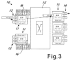
図を参照すると、図1は、全体として参照番号10により指定された、ネットワーク間の相互接続プラットフォームを実現する装置を示す図である。上記装置は、クライアントトラフィックカード11を備え、該カードの各々は、クライアントのネットワーク通信装置(当業者には容易に想像できるため図示しない)へ接続するための一定数のインタフェースポート12を有する。この装置はクライアントの物理的LANアクセスノードなどである。本図におけるクライアントインタフェースポートは、2枚の異なるトラフィックカード11の中にそれぞれ備えられているものとする(これらのトラフィックカードは、以下「クライアントカード(Client card)1」及び「クライアントカード2」として識別される)。実際には、各カードに備えられるインタフェースポートの数は異なってもよいし、カードの数も本実施形態におけるものとは異なってもよい。
Referring to the figure, FIG. 1 is a diagram illustrating an apparatus for implementing an interconnection platform between networks, designated generally by the
次いで、ネットワークセクションへの接続用として自身のインタフェースポート14を有するラインカード13(本例における3つのラインカードは、「ラインカード(Line card)1」、「ラインカード2」及び「ラインカード3」として識別される)が存在する。上記ネットワークセクションにVPLサービスを提供するためにクライアントカードを接続することが望ましい。インタフェースポートの数が異なる可能性があるため、ラインカードについても、実際には枚数が図示の枚数とは異なる場合がある。
Next, a
当業者には容易に想像できるように、インタフェースは、クライアント側のポート用かライン側のポート用かのいずれかによって、種類別及び利用する接続技術に応じて周知のように異なるものとなる。 As can be easily imagined by those skilled in the art, the interface varies depending on the type and connection technology used, depending on whether it is for a client side port or a line side port.
クライアントカードとラインカードとの間には、実装構成に応じて能動的又は受動的になり得る公知の相互接続ユニット、又は、スイッチ(交換機)15が存在し、クライアントカード間、及び、任意のクライアントカードと任意のラインカード間の完全な接続性が提供される。 Between the client card and the line card, there are known interconnection units or switches (switches) 15 that can be active or passive depending on the mounting configuration, and between the client cards and any client Full connectivity between the card and any line card is provided.
図示の構造及びこれまで説明した構造は、それ自体公知のアーキテクチャであり、当業者には上記構造の実際の実装構成及び動作は容易に想像できるであろう。従って、上記構造を更に詳細に説明することはしない。 The illustrated structure and the structure described so far are architectures known per se, and the actual implementation and operation of the above structure will be readily conceivable to those skilled in the art. Therefore, the above structure will not be described in further detail.
個々のクライアントカードは、それぞれ自身のMACアドレステーブル16を保持し、該MACアドレステーブルは、ソース、入力ポート、VLAN及びテーブルを構成するエントリの有効期間(Age)に関する有効期間フィールドなど、別のフィールドのMACアドレスに関する情報を含む。図1は、アドレスがクライアントから学習される動作の第1のステップを示す図である。一例として、クライアントカード1のポート12(「Port 2」として識別される)に接続されたクライアント装置であって、MACアドレスYYにより識別される遠隔地のクライアント装置が、例えばVLANラベルとして5を付与されたトラフィックを送信すると仮定する。この情報はクライアントカード1により直ちに学習され、クライアントカード1のMACアドレステーブルに一時的に記憶される。クライアントカード1は、(クライアント側と基幹回線側双方の)すべての可能な宛先へトラフィックを送信する。というのは、クライアントカード1は、まだVLANラベル「5」について学習しておらず、その正確な宛先についての情報を有していないからである。上記プロセスはフラッディングとして周知のものである。
Each individual client card maintains its own MAC address table 16, which is another field such as a validity period field for the validity period (Age) of the entries that make up the source, input port, VLAN, and table. Information on the MAC address of FIG. 1 is a diagram illustrating a first step of an operation in which an address is learned from a client. As an example, a client device connected to the port 12 (identified as “
従って、クライアントカード2にはクライアントカード1と同じ情報が与えられる。唯一の違いは、与えられた情報が、クライアントカード1から来たものであるために、スイッチ15を介して学習されたという点である。この状況は、2枚のクライアントカードの各テーブル16として、図1に示した通りである。入力ポートは明らかに異なるもののそれ以外について、各テーブル16は、同じ情報を登録している。
Therefore, the same information as the
図2は、クライアントカードがラインからアドレスを学習する学習過程の次のステップを示す。或る一定の時間(例えば、10秒と仮定する)後、ラインカード1を介してMACアドレスZZからトラフィックが到着し、該トラフィックは、VPLSの一部であるすべてのクライアントカードへ送信される。基幹回線(トランク)から到着したパケットは、クライアントカードの間でさらなる転送を行わないように構成されたクライアントカードにのみ転送され、周知の水平分割原理を順守してループを回避する。
FIG. 2 shows the next step in the learning process in which the client card learns an address from the line. After a certain amount of time (for example, 10 seconds), traffic arrives from the MAC address ZZ via the
新たな情報が双方のクライアントカードのMACテーブルに挿入される。MACテーブルにおいて有効期間を秒で表す有効期間フィールドは、自動的に更新されるか、ゼロにセットされる。 New information is inserted into the MAC tables of both client cards. The validity period field representing the validity period in seconds in the MAC table is automatically updated or set to zero.
テーブル内には、現在、送信を開始したクライアント装置から到着したトラフィックについてのソースと宛先情報とが存在している。クライアントカード1は、そのMACテーブルの中にソースと宛先の双方を保持する。従って、YYからZZへの送信を継続するために、クライアントカードから適当なラインカードへの単純な転送以外のフラッディングは不要となる。クライアントカード2は、この接続に関する新たな情報をクライアントカード1から受信することはない。そのため、結果として、クライアントカード2に備えられたMACテーブルにおいて、このアドレスの有効期間フィールドの値は増加することになる。
In the table, there are currently source and destination information for traffic arriving from the client device that started transmission. The
上記処理のすべてが図3に示されており、この処理では、MACアドレスYYからアドレスZZへの送信開始からの有効期間は、例えば100秒であると仮定されている。したがって、クライアントカード2のMACテーブルの有効期間フィールドは100の数字に達している。
All of the above processes are shown in FIG. 3. In this process, it is assumed that the effective period from the start of transmission from the MAC address YY to the address ZZ is, for example, 100 seconds. Therefore, the validity period field of the MAC table of the
これまでに説明したメカニズムは当業者には周知のメカニズムである。 The mechanisms described so far are well known to those skilled in the art.
従来技術による実現形態では、所定の有効期間(通常300秒)に達すると、MACテーブル内の対応するエントリは削除される。しかし、このことは、高いリソースの消費という上述の問題を引き起こす原因となる。実際、ラインカード1に到着する、アドレスZZからアドレスYY方向へのトラフィックを、入力のラインカード1から、VPLSに属するすべてのクライアントカードへ転送することは不可能である。転送できない場合、ラインカード内に別のMACアドレステーブルを一時的に記憶し、このテーブルを保持しなければならないことになる。
In the implementation according to the prior art, when a predetermined validity period (usually 300 seconds) is reached, the corresponding entry in the MAC table is deleted. However, this causes the above-mentioned problem of high resource consumption. In fact, it is impossible to transfer the traffic arriving at the
クライアントカード1が、自身のMACアドレステーブル内に正確な情報を有し、それにより、トラフィックを処理して、該トラフィックをクライアントネットワークへ転送することができる。これに対して、クライアントカード2は、自身が備えているMACアドレステーブル内でMACアドレスYYに関連付けられたエントリが期限切れとなってしまうため、すでにこの情報を有していない。したがって、クライアントカード2がとることのできる唯一のアクションは、図4に示されているように、VPLSに関与するクライアントネットワークへ向かっているすべてのポートに対するフラッディングを実現することである。この結果、クライアントネットワークのリソースの不適当な消費は生じなくなる。
The
図5に示すように、本発明に従って、上記処理を全て回避するために、MACアドレステーブルの有効期間フィールドにおいて事前に設定された最大の数字に達した場合、エントリを自動的に削除せずに、MACアドレステーブルの上記特定のエントリに含まれている情報を確認して、上記エントリを削除できるか、好適に更新する必要があるかの判定を行うようにする。 As shown in FIG. 5, in order to avoid all the above processing according to the present invention, when the maximum number preset in the validity period field of the MAC address table is reached, the entry is not automatically deleted. Then, the information contained in the specific entry of the MAC address table is confirmed, and it is determined whether the entry can be deleted or preferably updated.
上記処理を達成するために、図5でわかるように、制御装置18をクライアントカード2に対して装備し、これにより最大の数字に達したことを検出し、最大の数字に達すると、テーブルのエントリ内において仲間として関連付けられている他のクライアントカード、すなわち、MACクライアントアドレスからトラフィックを受信するクライアントカードへ、同期要求を送信する。しかしながら、このような制御装置は、選択された実装構成に従って、装置10の別のユニット(別の例としては中央制御ユニット)の中に存在するように構成してもよいことを付記しておく。
In order to achieve the above processing, as can be seen in FIG. 5, the
特に、仲間として関連付けられている別のカード(上記例ではクライアントカード1)が同期要求を受信し、当該カードが備えている応答装置19は、対応するエントリの有効期間フィールドの内容に応じて更新応答又は削除応答を送信する。好適には、一般に及び実装構成に応じて、装置10の別のユニット(一例として中央制御ユニット)の中に存在するようにしてもよい。応答装置19は、自身の対応するエントリの有効期間フィールドに含まれている数字と同じ数字を更新用の数字として送信することが望ましい。換言すれば、トラフィックを受信したクライアントカードのMACアドレステーブルは、必然的により直近のものであり、これが使用されるようになる。
In particular, another card associated as a friend (
同期要求及びこの結果生じる情報の交換は、図5の参照番号17により示されている。
The synchronization request and the resulting exchange of information is indicated by
クライアントカード1の有効期間フィールドの数字でさえその最大の数字となった場合には、削除信号が送信され、エントリは、すでに無用であるという理由で双方のカードで削除されることになる。この処理は図6に示されている。
If even the number in the validity period field of the
本明細書に記載の説明によって、当業者には制御装置と応答装置とが容易に想像できるであろう。説明を単純化する目的で、図には本発明についての説明を行う際に有用な手段のみを示したが、言うまでもなく、制御装置18及び応答装置19はすべてのクライアントカード11の中に存在する。
From the description provided herein, one of ordinary skill in the art will readily be able to imagine a control device and a response device. For the purpose of simplifying the description, only the means useful in explaining the present invention are shown in the figure, but it goes without saying that the
カード間での継続的なメッセージの交換が不要なため、実際に必要なときに、必要なエントリに対してのみ、同じVPLSに属した複数のクライアントカードに存在する各MACアドレステーブルの同期を維持することで、上述した目的が達成されることはすでに明白である。上記処理を行うために、本発明は、エントリがまだ使用中である可能性がある場合、MACアドレステーブルのエントリの削除を許可しないようにするために、(VPLSに関与するクライアントカードの数とは無関係に)複数ペアのクライアントカード間での1回だけの通信を必要とするものである。実際、MACアドレステーブルの上記エントリに含まれている情報により、クライアントネットワークへ不要なパケットを送信しないようにすることが可能となり、したがって、前記追加の最低限必要な帯域及びリソースの浪費が防止されることになる。 Since there is no need to continuously exchange messages between cards, the MAC address tables that exist in multiple client cards belonging to the same VPLS are kept in sync only for the necessary entries when actually needed. By doing so, it is clear that the above-mentioned purpose is achieved. In order to perform the above processing, the present invention determines the number of client cards involved in VPLS (and the number of client cards involved in (Regardless of which) only one communication is required between a plurality of pairs of client cards. In fact, the information contained in the above entry in the MAC address table makes it possible to avoid sending unnecessary packets to the client network, thus preventing the additional minimum required bandwidth and resource waste. Will be.
以上、2枚のクライアントカードを用いた例を示してきたが、この例を任意の枚数のカードへ拡張できることは明らかである。というのは、エントリの更新のための通信は、それらのMACアドレステーブルの対応するエントリに含まれるポート情報により関連付けられる複数ペアのクライアントカード間で、上述のメカニズムと同様に常に行われるからである。 The example using two client cards has been described above, but it is obvious that this example can be extended to an arbitrary number of cards. This is because the communication for updating the entries is always performed in the same manner as the above-described mechanism between a plurality of pairs of client cards associated by the port information included in the corresponding entries of the MAC address table. .
本発明は、MACアドレステーブルのラインカードへの保存及び保持を強いるものではなく、また、同期されるすべてのクライアントカードの完全なMACアドレステーブルの保持を強いるものでもないために、カード間の重い制御トラフィックを回避できるという利益をもたらすものとなる。さらに、本発明は、VPLS内の特定のトラフィック接続に直接関与しないクライアントカードによるクライアントに対するフラッディング問題を解決し、並びに、厳密に必要かつ有用な場合に、複数ペアのクライアントカードだけの間で制御通信を利用して、クライアントカード間の制御通信を最小限にとどめるものである。本質的に、本発明は、ネットワーク通信事業者と、それらのクライアントとの双方に対して、最も単純でかつ最も効果的な態様でVPLSサービスを提供することを可能にするものである。 The present invention does not force the storage and retention of the MAC address table on line cards, nor does it force the retention of the complete MAC address table of all synchronized client cards. The benefit is that control traffic can be avoided. Furthermore, the present invention solves the flooding problem for clients with client cards that are not directly involved in a specific traffic connection in VPLS, and controls communication between multiple pairs of client cards only when strictly necessary and useful. Is used to minimize control communication between client cards. In essence, the present invention allows VPLS services to be provided in the simplest and most effective manner to both network operators and their clients.
当然のことながら、本発明の革新的な原理を適用する実施形態についての上記記載は、本願で要求されている排他的権利の範囲内で本発明を限定しない前記原理の例として示されている。例えば、インタフェースとクライアントカードへの分割、及び、インタフェースとラインカードへの分割が、主として説明と理解の便宜上、本明細書で示されている。当業者には容易に想像できるように、相互接続プラットフォームは、インタフェースポートを有する一般的な第1の一連のカードと、インタフェースポートを有する一般的な第2の一連のカードとを、より一般的な形態のうちの1つの形態で有するものである。これらのカードは相互接続ユニットによる相互接続が可能である。また、上記2枚の一連のカードのうちの一方の複数のカードはMACアドレステーブルに装備され、該テーブルは本発明の原理に従って管理される。さらに「カード」の定義は、必ずしも他のカードと物理的に分離しているカードとして理解する必要はない。この意味で、「カード」とは、自身のMACアドレステーブと、該テーブルに基づくトラフィックルート論理回路とを有するインタフェースポートのグループとして理解することができる。 Of course, the above description of embodiments applying the innovative principles of the present invention has been presented as examples of the principles that do not limit the present invention within the scope of the exclusive rights required herein. . For example, the division into an interface and a client card, and the division into an interface and a line card are shown here mainly for convenience of explanation and understanding. As can be readily imagined by those skilled in the art, an interconnection platform is more commonly used with a generic first series of cards having interface ports and a generic second series of cards having interface ports. One of these forms. These cards can be interconnected by an interconnection unit. A plurality of cards in one of the two series of cards are provided in the MAC address table, and the table is managed according to the principle of the present invention. Further, the definition of “card” does not necessarily have to be understood as a card that is physically separated from other cards. In this sense, a “card” can be understood as a group of interface ports having their own MAC address table and traffic route logic based on the table.
Claims (10)
前記システムは、第1の一連のインタフェースポートカード(11)と、第2の一連のインタフェースポートカード(13)と、相互接続ユニット(15)とを含み、
前記相互接続ユニット(15)は、少なくとも前記第1の一連のインタフェースポートカード(11)に含まれるカードと、前記第2の一連のインタフェースポートカード(13)に含まれるカードとの間を相互接続するとともに、前記第1の一連のインタフェースポートカード(11)に含まれる複数のカード間を相互接続するように構成されており、
前記システムは、前記相互接続ユニットを介して前記複数のインタフェースポート間で転送されるトラフィックについてアドレス指定するための、前記第1の一連のインタフェースポートカード(11)に含まれる各カードにそれぞれ関連付けられた複数のMACアドレステーブル(16)を備えており、
前記MACアドレステーブルに登録されている各エントリは、該エントリの時間的な有効期限を定義するための有効期限フィールドを備えており、
前記方法は、
前記第1の一連のインタフェースポートカード(11)に含まれる第1インタフェースポートカードにおいて、前記エントリの有効期限フィールドが所定の最長期限の数字に達したか否かを確認するステップと、
前記第1の一連のインタフェースポートカード(11)に含まれる第1インタフェースポートカードにおいて、前記所定の最長期限に達すると、前記第1の一連のインタフェースポートカード(11)に含まれる第2インタフェースポートカードに同期要求を送信するステップと、
前記第2インタフェースポートカードにおいて、前記同期要求を受信すると、前記第2インタフェースポートカードに関連付けられているMACアドレステーブルにおける対応したエントリの有効期限フィールドに登録されている数字であって、前記第1インタフェースポートカードにおいて更新対象のエントリにおける有効期限フィールドの数字と相互に関連付けられている数字を示す応答を、前記更新対象のエントリを更新するために送信するステップと
を有することを特徴とする方法。A method of managing a MAC address table in the system (10) comprising a plurality of interface ports (12, 14) for connecting the system to a network,
The system includes a first series of interface port cards (11), a second series of interface port cards (13), and an interconnection unit (15);
The interconnection unit (15) interconnects at least a card included in the first series of interface port cards (11) and a card contained in the second series of interface port cards (13). And a plurality of cards included in the first series of interface port cards (11) are interconnected,
The system is associated with each card included in the first series of interface port cards (11) for addressing traffic forwarded between the plurality of interface ports via the interconnection unit. A plurality of MAC address tables (16),
Each entry registered in the MAC address table includes an expiration date field for defining a temporal expiration date of the entry,
The method
Checking whether the validity period field of the entry has reached a predetermined maximum number in the first interface port card included in the first series of interface port cards (11) ;
In the first interface port card included in the first series of interface port cards (11), when the predetermined maximum expiration date is reached, the second interface port included in the first series of interface port cards (11) Sending a synchronization request to the card ;
In the second interface port cards, upon receiving the synchronization request, a number which is registered in the expiration date field of the entry corresponds in the MAC address table associated with the second interface port cards, the first Transmitting a response indicating a number correlated with a number of an expiration date field in the entry to be updated in the interface port card in order to update the entry to be updated ;
Method characterized by having a.
を含むことを特徴とする請求項1に記載の方法。 In the first interface port card, the number registered in the expiration date field of the corresponding entry in the MAC address table of the second interface port card included in the first series of interface port cards (11) is used as the response. The method according to claim 1, further comprising the step of: copying from the expiration date field in the entry to be updated in the MAC address table of the first interface port card .
前記第2インタフェースポートカードにおける応答手段(19)が、前記第2インタフェースポートカードのMACアドレステーブルにおける対応したエントリの有効期限フィールドに含まれている数字に応じて、更新に使用される有効期限の数字を送信するか、又は、前記更新対象のエントリを削除するための削除コマンドを送信することを特徴とする請求項1に記載の方法。 The synchronization request is sent to the first series of interface port cards (11) by the updating means of the control device (18) in the first interface port card that updates the MAC address table including the entry to be updated. Transmitted to the included second interface port card,
The response means (19) in the second interface port card determines the expiration date used for the update according to the number included in the expiration date field of the corresponding entry in the MAC address table of the second interface port card. The method according to claim 1, wherein a number is transmitted or a delete command for deleting the entry to be updated is transmitted.
ネットワークを相互接続するための複数のインタフェースポート(12,14)を備えたプラットフォーム(10)を備え、該プラットフォームは、第1の一連のインタフェースポートカード(11)と、第2の一連のインタフェースポートカード(13)と、相互接続ユニット(15)とを含み、
前記相互接続ユニット(15)は、少なくとも前記第1の一連のインタフェースポートカード(11)に含まれるカードと、前記第2の一連のインタフェースポートカード(13)に含まれるカードとの間を相互接続するとともに、前記第1の一連のインタフェースポートカード(11)に含まれる複数のインタフェースポートカード間を相互接続するように構成されており、
前記第1の一連のインタフェースポートカード(11)に含まれる複数のインタフェースポートカードのそれぞれは、前記相互接続ユニットを介して前記複数のインタフェースポートカード間で転送されるトラフィックについてアドレス指定するための、複数のMACアドレステーブル(16)を備えており、
前記MACアドレステーブルに登録されている各エントリは、該エントリの時間的な有効期限を定義するための有効期限フィールドを備えており、
前記装置は、
前記第1の一連のインタフェースポートカード(11)のうち第1インタフェースポートカードが備える前記MACアドレステーブルにおける前記エントリの有効期限フィールドが所定の最長期限の数字に達したか否かを定期的に確認し、前記所定の最長期限に達すると、前記第1の一連のインタフェースポートカード(11)に含まれる第2インタフェースポートカードに対して同期要求を送信する制御手段(18)と、
前記第2インタフェースポートカードにおいて、供給された前記同期要求に対する応答として、前記第1の一連のインタフェースポートカード(11)に含まれる前記第2インタフェースポートカードのMACアドレステーブルにおける対応したエントリの有効期限フィールドに登録されている数字であって、前記第1インタフェースポートカードにおいて更新対象のエントリにおける有効期限フィールドの数字と相互に関連付けられている数字を示す応答を前記第1インタフェースポートカードへ送信する応答手段(19)と
を含むことを特徴とする装置。A device for interconnecting networks,
A platform (10) with a plurality of interface ports (12, 14) for interconnecting networks, the platform comprising a first series of interface port cards (11) and a second series of interface ports A card (13) and an interconnection unit (15),
The interconnection unit (15) interconnects at least a card included in the first series of interface port cards (11) and a card contained in the second series of interface port cards (13). And a plurality of interface port cards included in the first series of interface port cards (11).
Each of the plurality of interface port cards included in the first series of interface port cards (11) is for addressing traffic transferred between the plurality of interface port cards via the interconnection unit; A plurality of MAC address tables (16),
Each entry registered in the MAC address table includes an expiration date field for defining a temporal expiration date of the entry,
The device is
It is periodically checked whether or not the expiration date field of the entry in the MAC address table included in the first interface port card of the first series of interface port cards (11) has reached a predetermined maximum expiration date. And a control means (18) for transmitting a synchronization request to the second interface port card included in the first series of interface port cards (11) when the predetermined maximum time limit is reached;
In the second interface port card, as a response to the supplied synchronization request, the expiration date of the corresponding entry in the MAC address table of the second interface port card included in the first series of interface port cards (11) A response indicating a number registered in the field and indicating a number correlated with the number of the expiration date field in the entry to be updated in the first interface port card, to the first interface port card Means (19).
前記第1インタフェースポートカードにおける更新対象のエントリに対応しているエントリであって、前記第1の一連のインタフェースポートカード(11)に含まれる前記第2のインタフェースポートカードのMACアドレステーブルに登録されているエントリの有効期限の数字を前記応答として送信する
ことを特徴とする請求項5に記載の装置。The response means (19)
An entry corresponding to an entry to be updated in the first interface port card , which is registered in the MAC address table of the second interface port card included in the first series of interface port cards (11). 6. The apparatus according to claim 5, wherein an expiration date number of an existing entry is transmitted as the response .
前記第1インタフェースポートカードにおける更新対象のエントリに対応しているエントリであって、前記第1の一連のインタフェースポートカード(11)に含まれる前記第2のインタフェースポートカードのMACアドレステーブルに登録されているエントリの有効期限の数字が所定の最長期間に達すると、削除コマンドを送信する
ことを特徴とする請求項5に記載の装置。The response means (19)
An entry corresponding to an entry to be updated in the first interface port card , which is registered in the MAC address table of the second interface port card included in the first series of interface port cards (11). 6. The apparatus according to claim 5 , wherein a delete command is transmitted when the number of expiration dates of a given entry reaches a predetermined maximum period.
ことを特徴とする請求項7に記載の装置。8. The apparatus according to claim 7, wherein when the response means (19) transmits the delete command, the control means (18) deletes an entry corresponding to the entry to be updated.
Applications Claiming Priority (3)
| Application Number | Priority Date | Filing Date | Title |
|---|---|---|---|
| IT001704A ITMI20051704A1 (en) | 2005-09-15 | 2005-09-15 | OPTIMIZED SYNCHRONIZATION OF TABLES OF MAC ADDRESSES IN NETWORK INTERCONNECTION EQUIPMENT |
| ITMI2005A001704 | 2005-09-15 | ||
| PCT/EP2006/065648 WO2007031391A1 (en) | 2005-09-15 | 2006-08-24 | Optimized synchronization of mac address tables in network interconnection apparatuses |
Publications (2)
| Publication Number | Publication Date |
|---|---|
| JP2009508420A JP2009508420A (en) | 2009-02-26 |
| JP4763791B2 true JP4763791B2 (en) | 2011-08-31 |
Family
ID=36238721
Family Applications (1)
| Application Number | Title | Priority Date | Filing Date |
|---|---|---|---|
| JP2008530461A Expired - Fee Related JP4763791B2 (en) | 2005-09-15 | 2006-08-24 | Optimized synchronization of MAC address tables in network interconnect devices |
Country Status (8)
| Country | Link |
|---|---|
| US (1) | US7929545B2 (en) |
| EP (1) | EP1925128B1 (en) |
| JP (1) | JP4763791B2 (en) |
| CN (1) | CN101305557B (en) |
| AT (1) | ATE464719T1 (en) |
| DE (1) | DE602006013656D1 (en) |
| IT (1) | ITMI20051704A1 (en) |
| WO (1) | WO2007031391A1 (en) |
Families Citing this family (14)
| Publication number | Priority date | Publication date | Assignee | Title |
|---|---|---|---|---|
| JP4794670B2 (en) * | 2007-09-05 | 2011-10-19 | 富士通株式会社 | Route control device |
| US8392606B2 (en) * | 2008-09-23 | 2013-03-05 | Synapse Wireless, Inc. | Wireless networks and methods using multiple valid network identifiers |
| US8155150B1 (en) * | 2009-03-11 | 2012-04-10 | Juniper Networks, Inc. | Cooperative MAC learning/aging in highly distributed forwarding system |
| US9727508B2 (en) | 2009-04-27 | 2017-08-08 | Intel Corporation | Address learning and aging for network bridging in a network processor |
| CN102437947B (en) * | 2010-09-29 | 2014-04-16 | 杭州华三通信技术有限公司 | Method and device for preventing interruption of service |
| TWI427972B (en) * | 2010-10-26 | 2014-02-21 | Accton Technology Corp | Network device with creating path data and method thereof |
| US9019973B1 (en) * | 2012-09-28 | 2015-04-28 | Juniper Networks, Inc. | Static MAC address propagation in multipoint network services |
| US9043911B1 (en) | 2014-01-03 | 2015-05-26 | Juniper Networks, Inc. | Distributed learning and aging for management of internet protocol (IP) addresses |
| US9246748B2 (en) * | 2014-03-26 | 2016-01-26 | Mitsubishi Electric Research Laboratories, Inc. | Optical channel data unit switch with distributed control |
| US9658984B2 (en) | 2014-07-15 | 2017-05-23 | Cisco Technology, Inc. | Method and apparatus for synchronizing multiple MAC tables across multiple forwarding pipelines |
| US10075369B2 (en) * | 2015-04-27 | 2018-09-11 | Dell Products Lp | Systems and methods for improved switch performance by preventing flooding |
| US10158564B2 (en) * | 2016-11-17 | 2018-12-18 | Cisco Technology, Inc. | Border leaf traffic convergence in a software defined network |
| CN112751791B (en) * | 2020-12-30 | 2022-05-17 | 迈普通信技术股份有限公司 | Message forwarding and information processing method and device, electronic equipment and storage medium |
| CN115706724A (en) * | 2021-08-02 | 2023-02-17 | 中兴通讯股份有限公司 | Address synchronization method, switch, cross-device link aggregation system and storage medium |
Citations (1)
| Publication number | Priority date | Publication date | Assignee | Title |
|---|---|---|---|---|
| JP2004193821A (en) * | 2002-12-10 | 2004-07-08 | Fujitsu Ltd | Bridge instrument and its address learning method |
Family Cites Families (8)
| Publication number | Priority date | Publication date | Assignee | Title |
|---|---|---|---|---|
| US6604136B1 (en) * | 1998-06-27 | 2003-08-05 | Intel Corporation | Application programming interfaces and methods enabling a host to interface with a network processor |
| ATE350838T1 (en) * | 1998-10-05 | 2007-01-15 | Cit Alcatel | NETWORK SWITCHING DEVICE WITH DISTRIBUTION DATABASES DISTRIBUTED ON A USAGE BASIS |
| US6735198B1 (en) * | 1999-12-21 | 2004-05-11 | Cisco Technology, Inc. | Method and apparatus for updating and synchronizing forwarding tables in a distributed network switch |
| US6807172B1 (en) * | 1999-12-21 | 2004-10-19 | Cisco Technology, Inc. | Method and apparatus for learning and switching frames in a distributed network switch |
| KR100759169B1 (en) | 2002-07-22 | 2007-09-14 | 엘지노텔 주식회사 | Method of server managing and packet thrasmitting in network switch |
| US7149214B2 (en) * | 2003-11-04 | 2006-12-12 | Cisco Technology, Inc. | Dynamic unknown L2 flooding control with MAC limits |
| GB2414623B (en) * | 2004-05-27 | 2006-05-17 | 3Com Corp | Distributed bridging with synchronization of forwarding databases |
| US7593400B2 (en) * | 2006-05-19 | 2009-09-22 | Corrigent Systems Ltd. | MAC address learning in a distributed bridge |
-
2005
- 2005-09-15 IT IT001704A patent/ITMI20051704A1/en unknown
-
2006
- 2006-08-24 EP EP06792988A patent/EP1925128B1/en not_active Not-in-force
- 2006-08-24 CN CN2006800420088A patent/CN101305557B/en not_active Expired - Fee Related
- 2006-08-24 WO PCT/EP2006/065648 patent/WO2007031391A1/en active Application Filing
- 2006-08-24 AT AT06792988T patent/ATE464719T1/en not_active IP Right Cessation
- 2006-08-24 DE DE602006013656T patent/DE602006013656D1/en active Active
- 2006-08-24 JP JP2008530461A patent/JP4763791B2/en not_active Expired - Fee Related
- 2006-08-24 US US12/066,980 patent/US7929545B2/en not_active Expired - Fee Related
Patent Citations (1)
| Publication number | Priority date | Publication date | Assignee | Title |
|---|---|---|---|---|
| JP2004193821A (en) * | 2002-12-10 | 2004-07-08 | Fujitsu Ltd | Bridge instrument and its address learning method |
Also Published As
| Publication number | Publication date |
|---|---|
| US7929545B2 (en) | 2011-04-19 |
| CN101305557A (en) | 2008-11-12 |
| DE602006013656D1 (en) | 2010-05-27 |
| ITMI20051704A1 (en) | 2007-03-16 |
| JP2009508420A (en) | 2009-02-26 |
| EP1925128A1 (en) | 2008-05-28 |
| EP1925128B1 (en) | 2010-04-14 |
| WO2007031391A1 (en) | 2007-03-22 |
| ATE464719T1 (en) | 2010-04-15 |
| US20100085982A1 (en) | 2010-04-08 |
| CN101305557B (en) | 2012-09-05 |
Similar Documents
| Publication | Publication Date | Title |
|---|---|---|
| JP4763791B2 (en) | Optimized synchronization of MAC address tables in network interconnect devices | |
| CN100555948C (en) | A kind of switching equipment of in the stack exchanger system, being coupled of being used for | |
| US8369296B2 (en) | Distributed link aggregation | |
| JP5850471B2 (en) | COMMUNICATION SYSTEM, CONTROL DEVICE, NODE CONTROL METHOD, AND PROGRAM | |
| CN102263646B (en) | Multicasting within a distributed control plane of a switch | |
| CN110430076B (en) | Route management method and device | |
| JP2009538083A (en) | MAC address learning in distributed bridge | |
| JPH11346223A (en) | Atm switchboard | |
| CN102197627A (en) | Improved convergence of multicast traffic | |
| US20110299551A1 (en) | Method and Apparatus for Transferring Data Packets Between a First Network and a Second Network | |
| US20080069107A1 (en) | Scalable packet based network | |
| US9729948B1 (en) | Systems and methods for discovery of a controller in openflow networks | |
| CN100586088C (en) | Method for realizing virtual LAN aggregation and aggregation exchanger | |
| JPWO2013061604A1 (en) | Node device in ring network and route switching control method thereof | |
| US6438133B1 (en) | Load balancing mechanism for a translational bridge environment | |
| US9832041B2 (en) | Switch device and control method of switch device | |
| JP5218323B2 (en) | Information processing method and program related to relay device and transfer rule | |
| CN102195867A (en) | Network system, edge node, and relay node | |
| US20070008970A1 (en) | Packet data router apparatus and method | |
| JP2011055346A (en) | Switching hub and ring network | |
| CN101087243A (en) | Method and device for limiting multicast range in RPR | |
| JP5675528B2 (en) | Relay system | |
| JP5099632B2 (en) | Network system | |
| CN109639581B (en) | Table entry maintenance method and device of switch chip | |
| CN101540713B (en) | Method and device for establishing point-to-multipoint channel |
Legal Events
| Date | Code | Title | Description |
|---|---|---|---|
| A131 | Notification of reasons for refusal |
Free format text: JAPANESE INTERMEDIATE CODE: A131 Effective date: 20100628 |
|
| A521 | Request for written amendment filed |
Free format text: JAPANESE INTERMEDIATE CODE: A523 Effective date: 20100927 |
|
| A131 | Notification of reasons for refusal |
Free format text: JAPANESE INTERMEDIATE CODE: A131 Effective date: 20101206 |
|
| TRDD | Decision of grant or rejection written | ||
| A01 | Written decision to grant a patent or to grant a registration (utility model) |
Free format text: JAPANESE INTERMEDIATE CODE: A01 Effective date: 20110530 |
|
| A01 | Written decision to grant a patent or to grant a registration (utility model) |
Free format text: JAPANESE INTERMEDIATE CODE: A01 |
|
| A61 | First payment of annual fees (during grant procedure) |
Free format text: JAPANESE INTERMEDIATE CODE: A61 Effective date: 20110609 |
|
| FPAY | Renewal fee payment (event date is renewal date of database) |
Free format text: PAYMENT UNTIL: 20140617 Year of fee payment: 3 |
|
| R150 | Certificate of patent or registration of utility model |
Free format text: JAPANESE INTERMEDIATE CODE: R150 |
|
| R250 | Receipt of annual fees |
Free format text: JAPANESE INTERMEDIATE CODE: R250 |
|
| R250 | Receipt of annual fees |
Free format text: JAPANESE INTERMEDIATE CODE: R250 |
|
| LAPS | Cancellation because of no payment of annual fees |