JP4763243B2 - Image forming apparatus with simulated drum support - Google Patents
Image forming apparatus with simulated drum support Download PDFInfo
- Publication number
- JP4763243B2 JP4763243B2 JP2004067753A JP2004067753A JP4763243B2 JP 4763243 B2 JP4763243 B2 JP 4763243B2 JP 2004067753 A JP2004067753 A JP 2004067753A JP 2004067753 A JP2004067753 A JP 2004067753A JP 4763243 B2 JP4763243 B2 JP 4763243B2
- Authority
- JP
- Japan
- Prior art keywords
- support
- image forming
- forming apparatus
- supports
- section
- Prior art date
- Legal status (The legal status is an assumption and is not a legal conclusion. Google has not performed a legal analysis and makes no representation as to the accuracy of the status listed.)
- Expired - Fee Related
Links
Images
Classifications
-
- G—PHYSICS
- G03—PHOTOGRAPHY; CINEMATOGRAPHY; ANALOGOUS TECHNIQUES USING WAVES OTHER THAN OPTICAL WAVES; ELECTROGRAPHY; HOLOGRAPHY
- G03G—ELECTROGRAPHY; ELECTROPHOTOGRAPHY; MAGNETOGRAPHY
- G03G15/00—Apparatus for electrographic processes using a charge pattern
- G03G15/75—Details relating to xerographic drum, band or plate, e.g. replacing, testing
- G03G15/758—Details relating to xerographic drum, band or plate, e.g. replacing, testing relating to plate or sheet
Landscapes
- Physics & Mathematics (AREA)
- General Physics & Mathematics (AREA)
- Exposure And Positioning Against Photoresist Photosensitive Materials (AREA)
- Preparing Plates And Mask In Photomechanical Process (AREA)
- Registering Or Overturning Sheets (AREA)
- Discharging, Photosensitive Material Shape In Electrophotography (AREA)
- Rolls And Other Rotary Bodies (AREA)
Description
本発明は、画像の形成が可能な材料(画像形成可能材料という。)を円筒形に保持しておいて、該画像形成可能材料の画像形成が可能な表面(画像形成可能表面という。)に画像を形成する技術に関する。更に特定すると、本発明は、前記材料を従来から用いられている完全な形のドラムを用いることなしに、円筒形の形に保持する画像形成装置(image setting apparatus)に関するものである。 In the present invention, a material capable of forming an image (referred to as an imageable material) is held in a cylindrical shape, and the surface capable of forming an image of the imageable material (referred to as an imageable surface) is used. The present invention relates to a technique for forming an image. More particularly, the present invention relates to an image setting apparatus that retains the material in a cylindrical shape without using a conventionally used complete drum.
画像形成技術においては、画像形成可能材料(imageable material)の上に画像(image)を形成するために、内部が中空のドラム装置を用いることが知られている。この技術は、一般に、内部ドラム技術(internal drum technology)と呼ばれている。ドラム装置は、1つの円筒軸線の回りを該円筒軸線に沿って延びる部分を備えている。この部分は、円筒軸線に沿って連続しているが、円筒軸線に沿う方向から見た場合にはC字形の形状を呈するように、円筒軸線の回りの一部が開口させられている。画像形成可能材料(例えば感光フィルムまたは感光紙)は、そのドラム装置の内側に配置されて、該材料がドラム装置の内側の円筒面に押しつけられる。フィルムのドラム内面へのコンタクトは、ドラムの内面に達するように延びる孔に接続された真空装置を用いることにより達成される。更にまた、ドラムの内面とフレキシブルな媒体との間の摩擦に抗するために、種々の手段が用いられている。この摩擦は、ドラムの内面の内側でのフレキシブルな媒体の正確な位置決めを妨げる。 In image forming technology, it is known to use a drum device with a hollow interior to form an image on an imageable material. This technique is commonly referred to as internal drum technology. The drum device includes a portion extending around one cylindrical axis along the cylindrical axis. This portion is continuous along the cylindrical axis, but a part around the cylindrical axis is opened so as to exhibit a C-shape when viewed from the direction along the cylindrical axis. An imageable material (eg, photosensitive film or paper) is placed inside the drum device and the material is pressed against the cylindrical surface inside the drum device. Contact of the film to the drum inner surface is accomplished by using a vacuum device connected to a hole extending to reach the drum inner surface. Furthermore, various means are used to resist friction between the inner surface of the drum and the flexible medium. This friction prevents accurate positioning of the flexible media inside the inner surface of the drum.
画像形成可能材料に露出を施す露出装置の少なくとも一部がドラム装置の内部に配置される。露出装置は、例えば、レーザと、回転する反射部材(ミラーやプリズム等)とを備えている。レーザから発せられた光は、円筒軸線に沿うように指向されて、円筒軸線の回りを回転している反射部材に当てられる。光は反射部材を経て画像形成可能材料に向けて方向を変えられる。反射部材の回転により、画像形成可能材料を横切る方向の走査が行われ、反射部材の軸線方向への動きにより画像形成可能材料の軸線方向に沿った走査が進められる。 At least a portion of an exposure device that exposes the imageable material is disposed within the drum device. The exposure device includes, for example, a laser and a rotating reflecting member (such as a mirror or a prism). The light emitted from the laser is directed along the cylindrical axis and is applied to the reflecting member rotating around the cylindrical axis. Light is redirected through the reflective member toward the imageable material. Scanning in a direction across the imageable material is performed by rotation of the reflecting member, and scanning along the axial direction of the imageable material is advanced by movement of the reflecting member in the axial direction.
良好な画像を形成するために、円筒面は、理想的な円筒形状からの偏りを最小にするように製造されなければならない。そのような理想的な円筒面を有する均一なドラム装置を製造することは困難であり、またその製造には多大な費用がかかる。例えば、その製造には、内面の全体に亘って高度な機械加工の精度が必要とされる。またドラム装置はその大きさが固定され、比較的重くなる傾向がある。 In order to form a good image, the cylindrical surface must be manufactured to minimize deviations from the ideal cylindrical shape. It is difficult to produce a uniform drum device having such an ideal cylindrical surface, and its production is very expensive. For example, its manufacture requires a high degree of machining accuracy over the entire inner surface. Also, the drum device is fixed in size and tends to be relatively heavy.
画像形成技術ではまた、内部での画像形成を行わせるために2以上の環状のリングまたはディスクを利用することが知られている。更に詳しく述べると、画像形成可能材料は、実質上の(ヴァーチャルな)内部画像形成ドラムを形成するための複数のリングの周囲にぴんと張られた状態で配置される(即ちフレキシブル材料が円筒形の状態に保持される)。従来の内部ドラム技術と同様に、該材料が円筒形状の状態にある間に、平行移動と回転運動とを行う反射部材(例えば可動プリズムまたは可動ミラー)を用いることにより画像形成可能材料の内面に露出が施される。しかしながら、従来の装置では、画像形成可能材料の内側に向いた画像形成可能表面にある程度リングをコンタクトさせることが必要とされた。そのためある決まった量の画像形成可能材料が使用できなくなり、無駄になることになる。またこのようなヴァーチャルな画像形成配置を有する或具体例では、反射部材が軸線方向に動かされる間に、リングまたはディスクが画像形成可能材料に沿って軸線方向に動かされてしまうことがあった。このようにリングが動くと、画像形成可能材料に対して擦り傷を生じさせることがあった。 Image forming techniques are also known to utilize two or more annular rings or discs to cause internal image formation. More specifically, the imageable material is placed tightly around a plurality of rings to form a substantially (virtual) internal imaging drum (ie, the flexible material is cylindrical). State). Similar to conventional internal drum technology, a reflective member (eg, a movable prism or a movable mirror) that translates and rotates while the material is in a cylindrical shape can be used on the inner surface of the imageable material. Exposure is given. However, prior devices required some contact of the ring to the imageable surface facing inward of the imageable material. For this reason, a fixed amount of image-forming material cannot be used and is wasted. Also, in certain embodiments having such a virtual imaging arrangement, the ring or disk may be moved axially along the imageable material while the reflective member is moved axially. This movement of the ring can cause scratches on the imageable material.
本発明の一態様によれば、画像形成可能材料からなるフレキシブルなセクション(section)の上に画像(イメージ)を形成するための画像形成装置が提供される。本発明の装置は、上記フレキシブルなセクション(切片)を或円筒軸線の周りに、そのセクションの画像形成可能表面を前記軸線に向けて内側に向けた状態で円筒形の形に保持するためのリテーナ手段を備えている。上記装置は、画像を形成するために内側に向いた画像形成可能表面に選択的に露出を施す手段を備えている。リテーナ手段は、前記軸線に沿って相互間に間隔をあけて配置された複数の弧状のサポート(support)を備えている。各サポートは、前記セクションの外側に向いた面と物理的に接触する湾曲した表面部分を備えている。複数のサポートは、前記軸線に沿って間隔をあけて配置された第1及び第2のサイドサポートと該第1及び第2のサイドサポートの間に配置された少なくとも一つの他のサポートとを含み、第1及び第2のサイドサポートはそれぞれ前記軸線に沿って間隔を隔てて配置された第1及び第2のサイドプレートに固定されている。また第1のサイドサポートと第2のサイドサポートとの間を他のサポートを経て前記軸線に沿って伸びるように設けられて前記第1のサイドサポートと前記他のサポートと前記第2のサイドサポートとに固定されたクロスメンバーが設けられ、このクロスメンバーにより、第1及び第2のサイドサポートと前記他のサポートとが相互に固定されることによって、複数のサポートのそれぞれの表面部分の前記軸線に対する径方向位置及び軸線方向位置が維持される。
本発明に係わる画像形成装置はまた、前記セクションをサポートと係合した状態に保持するための保持手段を備えている。この保持手段は、ローラアッセンブリを備え、該ローラアッセンブリは、2つのローラを備えていて、該2つのローラが、セクションを通過させる挟み込み部を形成する。各ローラは、円筒形に形成された外面を有し、少なくとも一つのローラは、前記円筒形の外面上に突出した表面部分を有している。この少なくとも一つのローラの円筒形の外面上に突出した表面部分は、該ローラの他の部分よりも大きい径を有する部分であって、該表面部分が、第1のサイドサポートに近接した位置と、第2のサイドサポートに近接した位置と、他のサポートに近接した位置とにそれぞれ設けられている。
According to one aspect of the present invention, there is provided an image forming apparatus for forming an image on a flexible section made of an imageable material. The apparatus of the present invention is a retainer for holding the flexible section (section) around a cylinder axis and in a cylindrical shape with the imageable surface of the section facing inwardly towards the axis. Means. The apparatus includes means for selectively exposing an imageable surface facing inward to form an image. The retainer means includes a plurality of arcuate supports spaced apart from one another along the axis. Each support includes a curved surface portion in physical contact with the outwardly facing surface of the section. The plurality of supports includes first and second side supports spaced apart along the axis, and at least one other support disposed between the first and second side supports, The first and second side supports are fixed to first and second side plates that are spaced apart from each other along the axis. The first side support and the second side support are provided so as to extend along the axis through another support, and are fixed to the first side support, the other support, and the second side support. A cross member is provided, and the first and second side supports and the other support are fixed to each other by the cross member, whereby a radial position of each surface portion of the plurality of supports with respect to the axis line and Axial position is maintained.
The image forming apparatus according to the present invention further includes holding means for holding the section in a state of being engaged with the support. The holding means includes a roller assembly, and the roller assembly includes two rollers, and the two rollers form a sandwiching portion through which the section passes. Each roller has an outer surface formed in a cylindrical shape, and at least one roller has a surface portion protruding on the outer surface of the cylindrical shape. A surface portion projecting on the cylindrical outer surface of the at least one roller is a portion having a larger diameter than the other portion of the roller, the surface portion being in proximity to the first side support; It is provided at a position close to the second side support and a position close to the other support, respectively.
本発明によれば、画像を形成する媒体と、実質的なドラムを形成する表面との間で生じる摩擦を低減させることができる。またサポートを使用することにより、媒体とドラムとの間に空気がトラップされるのを防ぐことができる。更に本発明によれば、完全な円筒形をしたホルダーを用いることなく、媒体を正確に円筒形の形に成形することができる。 According to the present invention, it is possible to reduce friction generated between an image forming medium and a surface forming a substantial drum. Also, by using the support, it is possible to prevent air from being trapped between the medium and the drum. Further, according to the present invention, the medium can be accurately formed into a cylindrical shape without using a complete cylindrical holder.
添付図面を参照して行われる以下の説明により、本発明の上記した特徴及び他の特徴と利点とが当業者に対して明らかにされる。
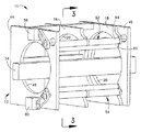
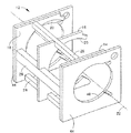
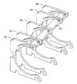
図1には、本発明による画像形成装置10の一実施形態が示されている。装置10は、第1のサイド・サポート14と、センター・サポート16と、第2のサイド・サポート18とを有する模擬ドラムリテーナ12(図2参照)を備えている。各サポート(例えばセンターサポート16、図3参照)は、中心軸線22に向かって内側に向いた滑らかな円環状の表面部分20を備えたほぼC字形の形状を有している。3つのサポート14ないし18(例えばセンター・サポート16,図3参照)の表面部分20は、すべて、中心軸線22からの半径が等しくなっている。図示の例において、各サポート(例えばセンター・サポート16、図3参照)の環状の表面部分20は、中心軸線22の周囲を完全に(周囲全体に亘って)は延びてはいない。表面部分20は、中心軸線22の周りに円弧(円の一部)を形成している。それ故に、サポート14ないし18は、湾曲した表面部分を備えた弧状のサポートである。一実施形態においては、表面部分20が中心軸線22の周りをほぼ250°に亘って延びている。しかしながら、中心軸線22の周りの表面部分20の円弧の範囲(円弧角)は、異なっていてもよい(即ち250°と異なっていてもよい)ことは理解されるべきである。
The above features and other features and advantages of the present invention will become apparent to those skilled in the art from the following description with reference to the accompanying drawings.
FIG. 1 shows an embodiment of an
3つのサポート14ないし18(図2参照)は、中心軸線22に沿って相互間に間隔をあけた状態で配置されている。サポートを相互に支えるために、複数の(図示の例では3個の)クロス・メンバー(cross member)26が、第1のサイド・サポート14と、センター・サポート16と、第2のサイド・サポートとの間を延びている。このようにして、サポート14ないし18が相互に固定されて、それらの内側に向いた表面部分20の中心軸線22に対する径方向位置及び軸線方向位置が維持されるように、サイド・サポート14ないし18が固定されている。
The three supports 14 to 18 (see FIG. 2) are arranged along the
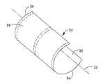
模擬ドラムリテーナ12(図2参照)は、図4に示されているように、画像形成可能材料30からなるフレキシブルなセクション(切片)を中心軸線22の周りに円筒形の形状に保持する。「円筒形の」という語には、広い意味を持たせることが意図されている。即ち、「円筒形」という語は、図4の例に示されているように中心軸線22の周囲全体に亘って完全には延びていないような形状を含む円筒に近いすべての形状を包含する意味で用いている。本明細書では、これらの点が理解されることを前提とした上で、議論を容易にするために、「円筒形の」という語を用いる。
The simulated drum retainer 12 (see FIG. 2) holds a flexible section (section) of
画像形成可能材料30は、画像形成可能表面32を有しており、この表面は、該材料が円筒形の形状にあるときに中心軸線22に向かって内側に向けられる。そのために、3つのサポート14ないし18(図2)が模擬内部ドラムを形成し、中心軸線22が円筒軸(円筒の中心軸線)となる。第1のサイド・サポート14は、画像形成可能な材料のセクションの第1の軸線方向端部34に近接するように配置され、第2のサイド・サポート18は、該材料のセクションの第2の軸線方向端部36に近接するように配置される。またセンター・サポート16は該材料のセクションの中間部分(mid-portion)に近接するように配置される。3つのサポート14ないし18は、図4に破線で示されたように、材料30のセクションの外側に向いた面に物理的に接触する。3つのサポート14ないし18は、画像形成可能材料30(図4)と最小限に接触する。異なった数の(例えば5個の)サポートを模擬ドラムリテーナに設けることができることが理解されるべきである。
The
第1及び第2のサイド・サポート14及び18はそれぞれ、第1及び第2のサイド・プレート44及び46に接続されている。図1及び図2から明らかなように、各サイド・プレート(例えばサイド・プレート44)は、矩形状の輪郭形状を有するように形成されていて、ほぼ円環状の開口部48を備えている。図示の例では、開口部48が、関連するサイド・サポート(図示の例ではサイド・サポート14)の表面部分により境界が定められる円と中心軸線を共有している。各サイド・プレート(例えばサイド・プレート44)の開口部48の半径は、関連するサイド・サポート(例えば14)の表面部分20の半径よりも小さい。従って、サイド・プレート44及び46は、模擬ドラムの軸線方向端部を形成する。
First and second side supports 14 and 18 are connected to first and
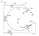
再び画像形成装置10(図1及び図3)に話を戻すと、装置10は、画像形成可能材料30の取扱いと像の形成とに用いる更に他の適宜の構造体を備えている。図示の例では、該構造体が、上側ローラ対52と、下側ローラ対54と、リニア/回転形の画像形成源(linear/rotational imaging stource)56(図1に軸線方向に延びるブロックとして概略的に図示されている。)とを備えている。更に、上記他の構造体は、上側及び下側のローラ対52及び54をそれぞれ動作させるための上側及び下側の駆動機構58及び60を備えていてもよい。上記構造体はまた、円筒形状に保持される材料30のフレキシブルなセクションを得るために、大容量の材料供給源から画像形成可能材料をカットするための構成62(図3参照)を備えていてもよい。
Returning again to the image forming apparatus 10 (FIGS. 1 and 3), the
種々の図面に示された構造を理解するために、以下の点に注意すべきである。即ち、材料をカットするための構成62は図1には示されていない。更に、リニア/回転形画像生成源56は図3には図示されていない。また、第2のサイド・プレートは図3には図示されていない。
In order to understand the structure shown in the various drawings, the following points should be noted. That is, the
図2に示された例において、上側及び下側のローラ対52及び54は、かなり似通った構成を有しており、上側及び下側の駆動機構58及び60もかなり似通った構成を有している。そこで、上側のローラ対52及びそれと関連する上側の駆動機構58についてのみ説明することにする。これらの説明が、下側のローラ対54及びそれと関連する下側の駆動機構60にもほぼ適用されることは理解されるべきである。上側のローラ対52は、サポート14ないし18のほぼC字形状の口部(開口部)の一方のエッジ(上側のエッジ)に近接した位置に配置されている。上側ローラ対52に対しては、第1のローラ64が中心軸線22と平行に延びており、第2のローラ66が第1のローラに隣接した位置を中心軸線22と平行に延びている。ローラ64,66は、第1及び第2のサイド・プレート44及び46に回転自在に支持されている。第1及び第2のローラ64及び66は、両者間に挟み込み部を形成する。ローラ64,66が回転した際に、画像形成可能材料が該挟み込み部を通して模擬ドラムリテーナ12に対して相対的に移動させられる。即ち、材料は、支持部材のC字形状の口部を通して移動させられる。この移動は、第1及び第2のローラ64及び66の少なくとも一方に(例えばベルト及びプーリからなる駆動装置を介して)接続された上側駆動機構58により行われる。材料が模擬ドラムリテーナ12の内側にあって、ローラ64,66が静止している状態では、ローラ対52により画像形成可能材料がサポートの内側に保持されてサポート14ないし18に対して押しつけられる。
In the example shown in FIG. 2, the upper and lower roller pairs 52 and 54 have a fairly similar configuration, and the upper and
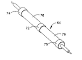
図示の例では、第1のローラ64が複数個(例えば3個)の突出部分70ないし74(図5参照)を備えていることに注意すべきである。突出部分70ないし74は、一般には、第2のサイド・サポート14に近接した位置と、センター・サポート16に近接した位置と、第2のサイド・サポート18に近接した位置とに配置される。一例では、突出部分70ないし74がローラ64の他の部分76,及び78よりも0.635mm(0.025インチ)だけ大きい径を有している。突出部が大きな径を有していることにより、突出部分70ないし74ではローラ対52の挟み込み部を通過している画像形成可能材料に対してより強いコンタクトがもたらされる。ローラ64の突出していない部分76及び78部分では、軽いコンタクトが行われる。これにより、強いコンタクトをしている部分が、ローラ対52から材料30に大部分の力を伝達する。これにより、3つのサポート14ないし18(即ち、第1のサイド・サポート、センター・サポート及び第2のサイド・サポート)の間で生じる画像形成可能材料30の曲げが最小にされる。このようにして、模擬ドラムリテーナ12内に配置されて保持された画像形成可能材料30が受ける完全な円筒形状からの歪みが最小にされる。
In the illustrated example, it should be noted that the
既に述べた画像形成装置は、フレキシブルな画像形成可能材料の連続したロールとともに用いることが意図されている。フレキシブルな画像形成可能材料の、長さが決められた、分離されたシートとともに使用するために、本発明の装置の有用な変形を行うことができる。この変形された装置は、既に説明されたものと同様な複数の突出部分を有する単一のローラ・アセンブリを備えたものとすることができる。このローラ・アセンブリはフレキシブルな画像形成可能材料のシートを画像形成装置の一端に供給するために用いられる。画像形成装置の他端側では、画像形成装置の円周に沿って挿入されたフレキシブルな画像形成可能材料の端部を、固定された機械的なストッパが位置決めすることになる。ローラ・アセンブリはフレキシブルな画像形成可能材料のシートをこのストッパに向けて押圧し、そのシートを円筒形のリングに対して押しつける。円筒形のリングの表面の接線方向に配置されたストッパ上の第2の面により、フレキシブルな画像形成可能材料シートの停止させられた端部が複数の円筒形リングの間で外側に曲がるのが阻止される。 The image forming apparatus already described is intended for use with a continuous roll of flexible imageable material. Useful variations of the apparatus of the present invention can be made for use with a separate, fixed length, sheet of flexible imageable material. This modified device may comprise a single roller assembly having a plurality of protrusions similar to those already described. This roller assembly is used to feed a sheet of flexible imageable material to one end of the image forming apparatus. On the other end side of the image forming apparatus, a fixed mechanical stopper positions the end portion of the flexible image-forming material inserted along the circumference of the image forming apparatus. The roller assembly presses a sheet of flexible imageable material against the stopper and presses the sheet against the cylindrical ring. The second face on the stopper, which is arranged tangential to the surface of the cylindrical ring, causes the stopped end of the flexible imageable material sheet to bend outward between the plurality of cylindrical rings. Be blocked.
本発明の画像形成装置の更に他の変形例は、カットされたフレキシブルな画像形成可能材料のシートの或長さの範囲で使用するために製造される。この変形例では、固定された機械的ストッパが、円筒形のリングの周方向の或範囲で位置調整することができるように設けられる。 Yet another variation of the image forming apparatus of the present invention is manufactured for use with a range of lengths of cut flexible imageable material sheets. In this variant, a fixed mechanical stopper is provided so that the position can be adjusted in a certain range in the circumferential direction of the cylindrical ring.
1つのブロックとして概略的に図示されているリニア/回転形画像生成源56に言及すると、該画像生成源は、画像形成可能材料30に選択的に画像を形成する機能を提供するものであり、そのような生成源の構成及び形態は、適当なものであればいかなるものでもよいということが理解されるべきである。そのような機能を果たす多くの画像生成源が知られている。従って、画像生成源の構成及び形態によって本発明の範囲が限定されることはない。或特定の実施形態においては、画像生成源56が、模擬リテーナドラム12の内側、及び模擬リテーナドラム内に保持された画像形成可能材料30の円筒形状の内側で、中心軸線22に沿って延びる直線移送バーを備えている。回転形の反射部材(例えばミラーまたはプリズム)が中心軸線に対して回転する間に、該反射部材が上記のバーに沿って移動し得るようになっている。露出エネルギー源(例えばレーザ)が、露出エネルギー(例えばレーザ光)を軸線に沿って指向させて、回転している反射部材に照射する。
Referring to a linear /
反射部材は、画像形成可能材料に向けて露出エネルギーの向きを変えて、その画像形成可能材料の上に画像を形成させる。反射部材は、該反射部材の各軸線方向位置で画像形成可能材料の円筒形状の1つの円の内側でエネルギーがスウィープ(sweep)されるように中心軸線22の周囲を回転させられる。反射部材はまた、画像形成可能材料の円筒形状の内側で、中心軸線22に沿って、個々の円形トレースが行われる機会を与えるために、軸線に沿って移動させられる。反射部材が動いている間に(例えば回転運動と直線運動とを行う間に)画像を形成させるために、エネルギーに変調が施されるか、または変調と同様の処理が施される。
The reflective member redirects the exposure energy toward the imageable material to form an image on the imageable material. The reflective member is rotated about the
大容量の供給源から画像形成可能材料を切断するための装置62(図3参照)は、いかなる構成及び形態を有していてもよい。該切断装置は、例えば、材料が模擬ドラムリテーナの内側に入った際に直ちにその材料に対して移動させられる刃を備えたものでよい。 The apparatus 62 (see FIG. 3) for cutting imageable material from a large volume source may have any configuration and configuration. The cutting device may include, for example, a blade that is immediately moved relative to the material when the material enters the inside of the simulated drum retainer.
図6は、上記実施形態で示された3つのサポートに代えて、5つのサポート78ないし86を用いた画像形成装置の一部の構成例を示している。また図6には機械的なストッパ90が図示されている。この装置は、連続した材料供給源から供給される材料からカットされたシートと共に用いるよりはむしろ、プリカットされたシート(図示せず。)と共に用いるために構成されている。そのため、各シートは、底部から供給され、移動させられて、その一端が頂部付近に配置されたストッパ90に接触させられる。機械的なストッパ90は、所定の位置に固定されていてもよく、サポート(複数)に対して相対的に変位し得るように設けられていてもよい。ストッパ90は、シートの末端が下側ローラの挟み込み部(図示せず。)に到達したちょうどその時に、該シートの挿入された端部が停止させられて、シートがサポートに押しつけられるように、サポート78ないし86の周方向に沿って位置決めされている。
FIG. 6 shows a configuration example of a part of an image forming apparatus using five
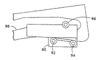
図7は、変位し得る機械的ストッパ90の構成例を詳細に示した図である。更に詳細に説明すると、2つのガイドローラ92及び94により、ストッパ90がドラムリングの表面に沿って変位するのが許容されている。第3のローラ(図7において上側に図示されている)96が、ドラムリングに形成されて比較的粗い仕上げ加工がされた円筒面98に対してバネで付勢され、これにより、下側ローラ92及び94がサポートのそれぞれの円筒面に対して付勢されている。
FIG. 7 is a diagram showing in detail a configuration example of the mechanical stopper 90 that can be displaced. More specifically, the two
本発明によれば、媒体(画像形成可能材料)と、実質的なドラム(模擬ドラム)を形成する表面との間で生じる摩擦が低減させられることが評価されるべきである。また上記サポートを使用することにより、媒体とドラムとの間に空気がトラップされるのが防止される。更に、サポートが媒体の画像形成可能な面には接触しないことが評価されるべきである。更にまた完全な円筒形をしたホルダーを用いることなく、媒体を正確な円筒形状に成形できることが評価されるべきである。 In accordance with the present invention, it should be appreciated that the friction generated between the media (imageable material) and the surface forming the substantial drum (simulated drum) is reduced. Further, by using the support, air is prevented from being trapped between the medium and the drum. Furthermore, it should be appreciated that the support does not contact the imageable side of the media. Furthermore, it should be appreciated that the media can be formed into an accurate cylindrical shape without using a complete cylindrical holder.
当業者であれば、本発明に関する上記の説明から、種々の改良と変形及び修正とを施すことに気づくであろう。そのような当業者の技術の範囲内でなされる改良、変形及び修正を添付された特許請求の範囲に含ませることが意図されている。 Those skilled in the art will recognize from the above description of the invention that various modifications, changes and modifications may be made. Such improvements, changes and modifications within the skill of the art are intended to be covered by the appended claims.
10 画像形成装置
12 模擬ドラムリテーナ
14,16,18 サポート
20 表面部分
22 中心軸線(円筒軸線)
78,80,82,84,86 サポート
90 ストッパ
DESCRIPTION OF
78, 80, 82, 84, 86 Support 90 Stopper
Claims (13)
前記セクションの画像の形成が可能な表面を円筒軸線に向かって内側に向けた状態で前記フレキシブルなセクションを前記円筒軸線の回りに円筒形状に保持するリテーナ手段と、
画像を形成するために、前記内側に向いた画像の形成が可能な表面に選択的に露出を施す手段とを具備し、
前記リテーナ手段は、前記軸線に沿って相互間に間隔をあけて配置された複数の弧状のサポートを備えていて、各サポートが、前記セクションの外側に向いた表面と物理的に接触するための湾曲した表面部分を有し、
前記複数のサポートは、前記軸線に沿って間隔をあけて配置された第1及び第2のサイドサポートと該第1及び第2のサイドサポートの間に配置された少なくとも一つの他のサポートとを含み、
前記第1及び第2のサイドサポートはそれぞれ前記軸線に沿って間隔を隔てて配置された第1及び第2のサイドプレートに固定され、
前記第1のサイドサポートと第2のサイドサポートとの間を他のサポートを経て前記軸線に沿って伸びるように設けられて前記第1のサイドサポートと前記他のサポートと前記第2のサイドサポートとに固定されたクロスメンバーが設けられ、
前記クロスメンバーにより、前記第1及び第2のサイドサポートと前記他のサポートとが相互に固定されることにより、前記複数のサポートのそれぞれの表面部分の前記軸線に対する径方向位置及び軸線方向位置が維持され、
前記セクションを前記サポートと係合した状態に保持するための保持手段を備え、
前記保持手段は、ローラアッセンブリを備え、
前記ローラアッセンブリは、2つのローラを備えていて該2つのローラが、前記セクションを通過させる挟み込み部を形成し、
各ローラは、円筒形に形成された外面を有し、
少なくとも一つのローラは、前記円筒形の外面上に突出した表面部分を有し、
前記少なくとも一つのローラの円筒形の外面上に突出した表面部分は、該ローラの他の部分よりも大きい径を有する部分であって、該表面部分が、前記第1のサイドサポートに近接した位置と、前記第2のサイドサポートに近接した位置と、前記他のサポートに近接した位置とにそれぞれ設けられている画像形成装置。 An image forming apparatus for forming an image on a flexible section made of a material capable of forming an image,
Retainer means for holding the flexible section in a cylindrical shape about the cylindrical axis with an imageable surface of the section facing inward toward the cylindrical axis;
Means for selectively exposing a surface capable of forming an image facing inward to form an image,
The retainer means comprises a plurality of arcuate supports spaced apart from one another along the axis, each support being in physical contact with an outwardly facing surface of the section. Has a curved surface portion;
The plurality of supports includes first and second side supports spaced apart along the axis and at least one other support disposed between the first and second side supports;
The first and second side supports are respectively fixed to first and second side plates that are spaced along the axis,
The first side support and the second side support are provided so as to extend along the axis through another support and fixed to the first side support, the other support, and the second side support. Cross member was established,
By the cross member, the first and second side supports and the other support are fixed to each other, so that the radial position and the axial position of each surface portion of the plurality of supports with respect to the axis are maintained. And
Holding means for holding the section in engagement with the support;
The holding means includes a roller assembly,
The roller assembly includes two rollers, and the two rollers form a sandwiching portion through which the section passes,
Each roller has an outer surface formed in a cylindrical shape,
At least one roller has a surface portion projecting over the cylindrical outer surface;
A surface portion projecting on the cylindrical outer surface of the at least one roller is a portion having a larger diameter than the other portion of the roller, and the surface portion is located close to the first side support. An image forming apparatus provided at a position close to the second side support and a position close to the other support .
第2のサイドサポートは、前記セクションの第2の軸線方向端部に近接するように配置され、
前記他のサポートである第3のサポートは、前記第1のサポートと第2のサポートとの間に軸線に沿って配置されている請求項1に記載の画像形成装置。 Three supports are provided, and the first side support is disposed so as to be close to the first axial end of the section,
A second side support is disposed proximate to a second axial end of the section;
The image forming apparatus according to claim 1, wherein the third support, which is the other support, is disposed along the axis between the first support and the second support.
第2のサイドサポートは前記セクションの第2の軸線方向端部に近接するように配置され、
前記他のサポートである第3ないし第5のサポートは、前記第1及び第2のサポートの間に相互間に間隔をあけた状態で軸線方向に沿って配置されている請求項1に記載の画像形成装置。 Five of the plurality of supports are provided, and the first side support is disposed to be close to the first axial end of the section,
A second side support is disposed proximate to a second axial end of the section;
The third to fifth supports, which are the other supports, are disposed along the axial direction with a space between the first and second supports. Image forming apparatus.
前記クロスメンバーは少なくとも3つ設けられている請求項1に記載の画像形成装置。The image forming apparatus according to claim 1, wherein at least three cross members are provided.
前記第1及び第2のサイドプレートの開口部は、それぞれ前記第1及び第2のサイドサポートの表面部分により境界が定められる円の半径よりも小さい半径を有するように設けられている請求項11に記載の画像形成装置。 The openings of the first and second side plates share a central axis with a circle delimited by the surface portions of the first and second side supports, respectively;
The openings of the first and second side plates are provided so as to have a radius smaller than a radius of a circle delimited by the surface portions of the first and second side supports, respectively. The image forming apparatus described .
Applications Claiming Priority (2)
| Application Number | Priority Date | Filing Date | Title |
|---|---|---|---|
| US10/385,146 US6771301B1 (en) | 2003-03-10 | 2003-03-10 | Image setting apparatus having drum simulating supports |
| US10/385,146 | 2003-03-10 |
Publications (2)
| Publication Number | Publication Date |
|---|---|
| JP2004272267A JP2004272267A (en) | 2004-09-30 |
| JP4763243B2 true JP4763243B2 (en) | 2011-08-31 |
Family
ID=32771569
Family Applications (1)
| Application Number | Title | Priority Date | Filing Date |
|---|---|---|---|
| JP2004067753A Expired - Fee Related JP4763243B2 (en) | 2003-03-10 | 2004-03-10 | Image forming apparatus with simulated drum support |
Country Status (4)
| Country | Link |
|---|---|
| US (1) | US6771301B1 (en) |
| EP (1) | EP1462872A3 (en) |
| JP (1) | JP4763243B2 (en) |
| CN (1) | CN100509413C (en) |
Family Cites Families (18)
| Publication number | Priority date | Publication date | Assignee | Title |
|---|---|---|---|---|
| US3025778A (en) | 1959-01-12 | 1962-03-20 | American Photocopy Equip Co | Photocopy apparatus and document carrier for same |
| GB1382124A (en) | 1972-05-19 | 1975-01-29 | Crosfield Electronics Ltd | Scanners for image reproduction |
| US4334770A (en) | 1978-12-22 | 1982-06-15 | Logetronics, Inc. | Method and apparatus for manipulating and transporting image media |
| CA1176879A (en) | 1981-02-06 | 1984-10-30 | Gary K. Starkweather | Single facet wobble free scanner |
| DE3531458A1 (en) | 1985-09-03 | 1987-03-05 | Boeger Scangraphic Gmbh Dr | PHOTOSETING DEVICE |
| DE3604360A1 (en) | 1986-02-12 | 1987-08-13 | Boeger Scangraphic Gmbh Dr | PHOTOSETING DEVICE |
| US4698647A (en) | 1986-05-13 | 1987-10-06 | Truvel Corporation | High resolution photographic film printer |
| IL80241A (en) | 1986-10-07 | 1991-03-10 | Scitex Corp Ltd | Internal drum plotter |
| US4803497A (en) | 1987-08-31 | 1989-02-07 | Dr.-Ing. Rudolf Hell Gmbh | Laser diode output power stabilization in a laser imagesetter |
| IL100635A (en) | 1992-01-12 | 1997-02-18 | Scitex Corp Ltd | Scanning apparatus |
| EP0630490A4 (en) | 1992-01-21 | 1995-09-06 | Exxtra Corp | Virtual drum imagesetter. |
| JPH0739166U (en) * | 1993-12-17 | 1995-07-14 | 大日本スクリーン製造株式会社 | Cylindrical inner drum |
| JP2928082B2 (en) * | 1994-03-31 | 1999-07-28 | 大日本スクリーン製造株式会社 | Cylindrical inner surface scanning device |
| US5867199A (en) * | 1995-03-28 | 1999-02-02 | Agfa Division, Bayer Corporation | Media guidance system for a scanning system |
| US5828399A (en) | 1995-11-13 | 1998-10-27 | Agfa-Gevaert | Imagesetter with rotating internal drum |
| US6097475A (en) | 1997-08-21 | 2000-08-01 | Agfa Corporation | Method and apparatus for orienting a recording media sheet on a support surface |
| US6240260B1 (en) * | 1999-01-29 | 2001-05-29 | Agfa Corporation | Method and apparatus for buffer transfer of media sheets between components in an imagesetting system |
| US6342914B1 (en) * | 2000-08-28 | 2002-01-29 | Eastman Kodak Company | Film registration slides |
-
2003
- 2003-03-10 US US10/385,146 patent/US6771301B1/en not_active Expired - Fee Related
-
2004
- 2004-03-10 CN CNB2004100330760A patent/CN100509413C/en not_active Expired - Fee Related
- 2004-03-10 JP JP2004067753A patent/JP4763243B2/en not_active Expired - Fee Related
- 2004-03-10 EP EP04100964A patent/EP1462872A3/en not_active Withdrawn
Also Published As
| Publication number | Publication date |
|---|---|
| CN1542563A (en) | 2004-11-03 |
| US6771301B1 (en) | 2004-08-03 |
| CN100509413C (en) | 2009-07-08 |
| EP1462872A3 (en) | 2008-03-26 |
| JP2004272267A (en) | 2004-09-30 |
| EP1462872A2 (en) | 2004-09-29 |
Similar Documents
| Publication | Publication Date | Title |
|---|---|---|
| EP0320137B1 (en) | A laser engraving machine for preparing rotary screen printing screens | |
| GB2038502A (en) | Image carrier | |
| US5835835A (en) | Fixing unit having press roller opening/closing mechanisms | |
| JPH0867374A (en) | Method and device to fix flexible sheet medium on rotary backing up surface | |
| JP4763243B2 (en) | Image forming apparatus with simulated drum support | |
| JPH09120654A (en) | Tightening and fixing device for disk-shaped information medium | |
| JP2020013052A (en) | Image forming system | |
| JP2001247232A (en) | Nip roller | |
| US6752080B2 (en) | Sheet material holding device | |
| JP4185269B2 (en) | Sheet material holding method and image recording apparatus | |
| JP2003223008A (en) | Exposure device and exposure method | |
| US20150138522A1 (en) | Roller mold manufacturing apparatus and method | |
| JP4666509B2 (en) | Image recording device | |
| JP4001779B2 (en) | Method for forming equally spaced slits on the surface of a belt-like structure and image forming apparatus | |
| JP3711080B2 (en) | Sheet material positioning device | |
| EP0679520A3 (en) | Multi-position lens assembly apparatus for exposing photosensitive media in a rotary printer | |
| JPH08113386A (en) | Sheet feeding device | |
| EP0878955A2 (en) | Apparatus for moving a radiation beam across a medium | |
| JP2003251782A (en) | Rotary drum | |
| JP2003043657A (en) | Thermal developing device and assembling method for the same | |
| US20040253005A1 (en) | Sheet body holding device | |
| JPH0745075Y2 (en) | Photosensitive material pressing device for flatbed scanning image recording device | |
| JP2003280210A (en) | Sheet material holding device | |
| JPH0859037A (en) | Carrying method for scanned body and device therefor | |
| JPH11268364A (en) | Imaging apparatus |
Legal Events
| Date | Code | Title | Description |
|---|---|---|---|
| A621 | Written request for application examination |
Free format text: JAPANESE INTERMEDIATE CODE: A621 Effective date: 20070306 |
|
| A131 | Notification of reasons for refusal |
Free format text: JAPANESE INTERMEDIATE CODE: A131 Effective date: 20100217 |
|
| A601 | Written request for extension of time |
Free format text: JAPANESE INTERMEDIATE CODE: A601 Effective date: 20100514 |
|
| A602 | Written permission of extension of time |
Free format text: JAPANESE INTERMEDIATE CODE: A602 Effective date: 20100519 |
|
| A521 | Request for written amendment filed |
Free format text: JAPANESE INTERMEDIATE CODE: A523 Effective date: 20100611 |
|
| A131 | Notification of reasons for refusal |
Free format text: JAPANESE INTERMEDIATE CODE: A131 Effective date: 20100914 |
|
| A521 | Request for written amendment filed |
Free format text: JAPANESE INTERMEDIATE CODE: A523 Effective date: 20101213 |
|
| A01 | Written decision to grant a patent or to grant a registration (utility model) |
Free format text: JAPANESE INTERMEDIATE CODE: A01 Effective date: 20110511 |
|
| A01 | Written decision to grant a patent or to grant a registration (utility model) |
Free format text: JAPANESE INTERMEDIATE CODE: A01 |
|
| A61 | First payment of annual fees (during grant procedure) |
Free format text: JAPANESE INTERMEDIATE CODE: A61 Effective date: 20110609 |
|
| FPAY | Renewal fee payment (event date is renewal date of database) |
Free format text: PAYMENT UNTIL: 20140617 Year of fee payment: 3 |
|
| R150 | Certificate of patent or registration of utility model |
Free format text: JAPANESE INTERMEDIATE CODE: R150 |
|
| LAPS | Cancellation because of no payment of annual fees |