JP4762020B2 - Molding method and molded product - Google Patents
Molding method and molded product Download PDFInfo
- Publication number
- JP4762020B2 JP4762020B2 JP2006085444A JP2006085444A JP4762020B2 JP 4762020 B2 JP4762020 B2 JP 4762020B2 JP 2006085444 A JP2006085444 A JP 2006085444A JP 2006085444 A JP2006085444 A JP 2006085444A JP 4762020 B2 JP4762020 B2 JP 4762020B2
- Authority
- JP
- Japan
- Prior art keywords
- molded product
- mold
- molding
- paint
- resin
- Prior art date
- Legal status (The legal status is an assumption and is not a legal conclusion. Google has not performed a legal analysis and makes no representation as to the accuracy of the status listed.)
- Expired - Fee Related
Links
Images


Landscapes
- Application Of Or Painting With Fluid Materials (AREA)
- Injection Moulding Of Plastics Or The Like (AREA)
Description
本発明は、成形品の成形方法に関し、特に、建設機械、農業機械、及び林業車両などの作業機械において、エンジングリルやマシンキャブ等の外装部材として用いられ、リブやボス等の凹凸を有する内側表面と外側表面との両面に塗膜を備える成形品を成形する方法に関する。 The present invention relates to a method of molding a molded article, and particularly used in exterior machines such as engine grills and machine cabs in work machines such as construction machines, agricultural machines, and forestry vehicles, and has an inner surface with irregularities such as ribs and bosses. The present invention relates to a method for forming a molded article having a coating film on both the surface and the outer surface.
例えば建設機械の1つである油圧ショベルは、下部走行体の上方に上部旋回体が旋回自在に設けられており、この上部旋回体には、オペレータキャブ、ブーム、カウンタウエイト等の他に、エンジンを収納するためのエンジングリルや、油圧機器等を収納するためのマシンキャブが配設されている。これらのエンジングリルやマシンキャブは、一般に寸法が大きく、またその内側表面(裏面)には補強用のリブやボス等が入り組んで設けられており、複雑な形状を有している。このため、エンジングリルやマシンキャブなどの外装部材は、一般に合成樹脂を反応射出成形法(以下、単にRIM法と略記する)により成形することによって作製されている。 For example, a hydraulic excavator, which is one of construction machines, is provided with an upper swinging body that can swing freely above a lower traveling body. In addition to an operator cab, a boom, a counterweight, and the like, the upper swinging body includes an engine. An engine grill for storing the machine and a machine cab for storing hydraulic equipment and the like are disposed. These engine grills and machine cabs are generally large in size, and on the inner surface (rear surface), reinforcing ribs, bosses and the like are provided in an intricate shape. For this reason, exterior members such as engine grills and machine cabs are generally produced by molding synthetic resin by a reaction injection molding method (hereinafter simply referred to as RIM method).
RIM法とは、ミキシングヘッドを用いて2種類以上の低分子量かつ低粘度の原料を混合し、混合すると同時に成形型内に射出する成形方法であり、大型で複雑な形状を有する成形品の成形に適している。また、RIM法は、射出成形に比べて成形圧力が低いため、成形型として金属製の成形型に比べて非常に安価な樹脂型を用いることができ、また型締装置も簡易なものを利用できるといった利点を有している。 The RIM method is a molding method in which two or more types of low molecular weight and low viscosity raw materials are mixed using a mixing head, mixed and injected into the mold at the same time. Molding of molded products having large and complex shapes Suitable for In addition, since the molding pressure of the RIM method is lower than that of injection molding, it is possible to use a resin mold that is very inexpensive compared to a metal mold as a mold, and use a simple mold clamping device. It has the advantage that it can.
一般に、作業機械の外装部材は、その外観品質を向上させて製品としての見栄えを良くするために、成形体の外側表面(外面)に塗装が施されている。このような外側表面に塗装が施された成形品をRIM法を用いて製造する方法の一例が、特開平5−42561号公報(特許文献1)や特開平8−72096号公報(特許文献2)などに記載されている。
In general, an exterior member of a work machine is coated on the outer surface (outer surface) of a molded body in order to improve the appearance quality and improve the appearance as a product. An example of a method for producing such a molded article having a coating on the outer surface by using the RIM method is disclosed in Japanese Patent Laid-Open No. 5-42561 (Patent Document 1) and Japanese Patent Laid-Open No. 8-72096 (
例えば、前記特許文献1には、合成樹脂のRIM法による成形おいて、成形と同時に加飾を行う加飾成形品の製造方法が記載されている。具体的には、RIM法により成形を行うに際して、先ず、真空吸引孔を有する雌型とシート加熱体との間に加熱軟化させた加飾用熱可塑性シートを介在させ、雌型と熱可塑性シートにより密閉された空間を雌型の真空吸引孔を通じて真空引きすることにより前記熱可塑性シートを雌型のキャビティ面の形状に沿う形に予備成形する。次に、雌型と雄型とを型締した後、所定形状に設計された金型のキャビティ内に合成樹脂の液状原料を射出することにより成形を行う。これにより、例えば大型かつ複雑な形状の成形品を成形する際に、加飾用熱可塑性シートが表面に一体的に被着された成形品を得ることができるとしている。
For example,
なお、前記特許文献1に記載されているような方法を用いて合成樹脂を成形する場合、成形時に発生するガスが上方に移動して、上型により成形される成形面には多数のボイドが形成されてしまう。このため、近年では、例えば加飾用シートが一体成形された成形品を製造する際に、一般に予備成形した加飾用シートを下型に配して成形が行われている。
In addition, when molding a synthetic resin using the method described in
これによって、例えば図4に示したように、成形体21において、上型により成形される内側表面22のリブ23やボスが形成されている部位にボイド24が形成されてしまうものの、外側の加飾用シートと合成樹脂との界面にはボイドが形成されない。このため、合成樹脂と加飾用シートとの接着性を確保して加飾用シートが剥離することを防ぎ、外側表面における意匠性の向上を図ることができる。またこの場合、成形時に形成されるボイド24は、成形体21を作業機械に取り付けたときには外部からは見えない成形体21の裏側に隠すことが可能となる。
As a result, for example, as shown in FIG. 4, in the
一方、前記特許文献2には、成形を行う際にインモールドコート成形法によって成形品の表面に塗膜を形成する場合において、RIM成形品の表面に色分けされた塗膜を形成することが可能な多色インモールドコート成形法が記載されている。特許文献2において、インモールドコート成形法とは、上型と下型で構成される金型のキャビティにRIM原料を充填してRIM成形品を成形した後、金型内でのRIM成形品の収縮により生じるRIM成形品表面と上型キャビティ面間の隙間に、上型の塗料注入孔から塗料を注入して、RIM成形品表面に塗膜を形成する方法である。
On the other hand, in
この特許文献2における成形方法は、インモールドコート成形法でRIM成形品の表面に塗膜を形成するに際し、塗膜形成側のキャビティ面に前記隙間を複数の区画に仕切る仕切り用凸部を設けるとともに、各区画のキャビティ面には各々塗料注入孔を設けておき、金型内でのRIM成形品の収縮後、仕切り用凸部で仕切られた隙間の各区画毎に、所定の色からなる塗料を各塗料注入孔から注入することに特徴を有している。このような成形方法によれば、仕切り用凸部で仕切られた各区画毎に所定の色からなる塗料を注入できるため、塗料が各区画間で混ざり合うことがなく、RIM成形品の表面に美麗に色分けされた塗膜を形成することできる。
In the molding method in
一方、成形体の外側表面に塗装を施す他の方法としては、例えば、成形品を成形した後に所定の領域を塗装する後塗装や、また、成形前に金型のキャビティ面に予め塗料を塗布しておき、同塗料を成形時に成形品に転写することによって外側表面に塗膜を成形一体化した成形品を作製する型内塗装といった技術が知られている。後塗装は、例えば成形品にサンディング、プライマー塗り、仕上げ塗装、焼付けなどの工程を行うことにより塗膜が形成されるが、作業工程が多くなり時間がかかるといった問題があった。一方、型内塗装は、成形前にスプレー等で金型のキャビティ面に塗料を塗布すれば良いため、工程数が少なく、コストを低く抑えることができるといった利点を有している。 On the other hand, other methods for applying the coating to the outer surface of the molded body include, for example, post-coating in which a predetermined region is applied after molding a molded product, or pre-coating the mold cavity surface before molding. In addition, there is known a technique such as in-mold coating for producing a molded product in which a coating film is molded and integrated on the outer surface by transferring the paint to a molded product at the time of molding. In the post-coating, for example, a coating film is formed by performing processes such as sanding, primer coating, finish coating, baking, etc. on the molded product, but there is a problem that it takes a lot of work steps and takes time. On the other hand, in-mold coating has the advantage that the number of steps can be reduced and the cost can be kept low because the coating can be applied to the cavity surface of the mold by spraying before molding.
ところで、作業機械のエンジングリルやマシンキャブにおいては、エンジン等を保護するために、ある程度の剛性や強度が求められるとともに、例えばメンテナンスのときに開閉を容易に行えるように軽量化が求められている。一方、合成樹脂の1つであるポリウレタンは、RIM法による成形が可能で、その成形性も優れている。また、硬質のポリウレタンを成形材料として用いることにより、軽量で高い剛性を有し、耐候性に優れた成形品が合理的に得られる。更に、ポリウレタンの成形では、成形体の表面にシボ模様を付与することが可能であるため、美麗で高級感のある成形品が得られるといった利点もある。 By the way, engine grills and machine cabs of work machines are required to have a certain degree of rigidity and strength in order to protect the engine and the like, and for example, weight reduction is required so that opening and closing can be easily performed during maintenance. . On the other hand, polyurethane, which is one of synthetic resins, can be molded by the RIM method and has excellent moldability. Further, by using hard polyurethane as a molding material, a molded product having a light weight, high rigidity, and excellent weather resistance can be reasonably obtained. Furthermore, in the molding of polyurethane, since it is possible to give a texture pattern to the surface of the molded body, there is an advantage that a beautiful and high-quality molded product can be obtained.
このため、現在では、作業機械のエンジングリルやマシンキャブなどに用いられる成形品では、成形材料として硬質ポリウレタンが多く用いられており、このような硬質ポリウレタンからなる成形体の外側表面に塗装を施す場合にも、前述のような塗装方法が用いられている。 Therefore, at present, hard polyurethane is often used as a molding material in molded products used for engine grills and machine cabs of work machines, and the outer surface of a molded body made of such hard polyurethane is coated. Even in this case, the above-described coating method is used.
また、油圧ショベルやホイールローダなどの作業機械は、その稼働時にエンジンや油圧機器などから発生する騒音が大きいという問題がある。従って、従来では、エンジンや油圧機器などから発生する騒音を低減するために、これらを収納するエンジングリルやマシンキャブの内側表面に吸音材を貼付する等の手段が講じられている。このような吸音材は、例えば上記のようなRIM法により外側表面に塗装が施された成形体を成形した後に、同成形体の内側表面に形成されているリブやボス等と干渉しないように所定の形状に裁断されて貼付されている。
一般に、油圧ショベルやホイールローダなどの作業機械においては、例えばエンジンや油圧機器などのメンテナンスを行う際にエンジングリルやマシンキャブ等の外装部材を開いて点検や整備などが行われる。その際、通常では外部からは見えないエンジングリルやマシンキャブの内側表面が人の目に付いてしまうため、近年では外装部材の内側表面の外観品質も向上させることが望まれている。 In general, in a working machine such as a hydraulic excavator or a wheel loader, for example, when maintenance is performed on an engine or a hydraulic device, an exterior member such as an engine grill or a machine cab is opened for inspection or maintenance. At that time, the engine grill and the inner surface of the machine cab, which are normally invisible from the outside, are visible to the human eye, and in recent years, it is desired to improve the appearance quality of the inner surface of the exterior member.
しかし、例えば前述のようなRIM法により成形された成形体の内側表面では、前述のようにリブやボスが形成されている部位にボイドが形成され易く、また例えば内側表面に吸音材を貼付する場合でもこれらの部位は吸音材が貼付されずに露出するため、外観品質の低下を招いていた。従って、エンジングリルやマシンキャブにおける内側表面の外観品質を向上させるために、外側表面だけでなく内側表面の全体に塗装を均一に施すことが求められてきている。 However, on the inner surface of the molded body molded by the RIM method as described above, for example, voids are easily formed at the sites where the ribs and bosses are formed as described above, and for example, a sound absorbing material is pasted on the inner surface. Even in these cases, these portions are exposed without the sound absorbing material being pasted, which causes a deterioration in appearance quality. Therefore, in order to improve the appearance quality of the inner surface of the engine grill and the machine cab, it has been demanded to uniformly coat not only the outer surface but also the entire inner surface.
しかし、例えば前記特許文献1に記載されているような方法により成形を行う場合、前述のように上型により成形される成形体の内側表面には、ボイドが形成される。このため、内側表面の品質を向上させるためには、内側表面に形成されたボイドを手作業で補修した後に後塗装を施さなければならず、作業の煩雑化を招き、コストへの負担も大きいといった問題があった。
However, for example, when molding is performed by the method described in
更に、例えば成形型として安価な樹脂型を用いて成形を行った場合には、成形時に樹脂型に塗布する離型剤として、金型の場合よりも融点が低い離型剤が用いられる。このため、成形後に樹脂型から成形品を取り出したときに、同成形品の表面には離型剤が一緒に貼り付いてくる。従って、上記のような後塗装を施すときには、塗膜の接着性を良くするために、塗装前に成形品にサンドブラスト処理を施して成形品から離型剤を除去することが必要となる。しかし、成形品の内側表面は、リブやボスが形成された複雑な面形状を有しているため、離型剤の除去やその後の塗装に多大な工程数が必要とされ、その作業も煩雑になる。 Further, for example, when molding is performed using an inexpensive resin mold as a mold, a mold release agent having a lower melting point than that of a mold is used as a mold release agent applied to the resin mold at the time of molding. For this reason, when the molded product is taken out from the resin mold after molding, a release agent is adhered to the surface of the molded product together. Accordingly, when post-coating as described above is performed, in order to improve the adhesion of the coating film, it is necessary to perform a sandblasting treatment on the molded product before coating to remove the release agent from the molded product. However, since the inner surface of the molded product has a complicated surface shape with ribs and bosses formed, a large number of steps are required for removal of the release agent and subsequent coating, which is also complicated. become.
また、成形品の外側表面と内側表面とに塗膜を形成する方法として、例えば図5の(a)及び(b)に模式図を示したように、成形時に、下型32に加飾シート33を配して成形品34の外側表面に塗膜を形成するとともに、成形品34の内側表面には前述の型内塗装を利用して、上型31のキャビティ面に予め塗料35を塗布しておくことにより塗膜35’を形成することが考えられる。
Moreover, as a method of forming a coating film on the outer surface and the inner surface of the molded product, for example, as shown schematically in FIGS. 5 (a) and 5 (b), the decorative sheet is attached to the
しかしこの場合も、成形時に成形品34の内側表面には(特にリブやボスの部位には)成形時に発生するガスが溜まってボイド36が形成される。このため、ボイド36が形成された成形品34の部位では塗料35を転写することができず、塗膜35’を安定して形成することができないという不具合があった。更に、塗料35を成形品34に転写できなかった場合、上型31の型内に塗料35が残存する。このため、成形後に上型31を清掃して残存した塗料35を除去する作業が必要とされ、コストアップを招く要因の一つとなる。
However, in this case as well, the gas generated during molding is accumulated on the inner surface of the molded product 34 (particularly at the ribs and bosses) during molding, and
なお、成形体の外側表面と内側表面とに塗膜を形成するその他の方法として、成形前に加飾シートを下型だけでなく、上型にも配することが考えられるが、この場合、加飾シートをリブやボス等が形成された内側表面の面形状に合わせて予備成形することが難しいという欠点がある。また、上型に配した加飾シートと合成樹脂との界面にボイドが形成されるため、両者間の接着性が低下するといった問題も生じる。 In addition, as another method of forming a coating film on the outer surface and inner surface of the molded body, it is possible to arrange the decorative sheet not only in the lower mold but also in the upper mold before molding, in this case, There is a drawback that it is difficult to preform the decorative sheet in accordance with the surface shape of the inner surface on which ribs, bosses and the like are formed. Moreover, since a void is formed at the interface between the decorative sheet arranged on the upper mold and the synthetic resin, there arises a problem that the adhesiveness between the two is lowered.
一方、前記特許文献2のように、成形品を成形した後に成形品と金型との間に形成される隙間に塗料を注入して成形品の表面に塗膜を形成する場合では、成形品の外側表面又は内側表面の何れか一方の面にしか塗膜を形成することができない。このため、他方の面は、その後に別途に塗装を行って塗膜を形成しなければならず、工程数が増加してコストアップに繋がってしまう。更に、特許文献2のインモールドコート成形法によって塗膜を形成するためには、成形品と金型との間に形成される隙間に塗料を非常に高い圧力で流し込む必要があるため、成形型として、高圧に十分に耐えることができる金型を作製しなければならず、コストへの負担が非常に大きくなるといった問題があった。
On the other hand, in the case of forming a coating film on the surface of a molded product by injecting a paint into a gap formed between the molded product and a mold after molding the molded product as in
本発明は上記従来の課題に鑑みてなされたものであって、その具体的な目的は、成形時のボイドの発生を防いで、外側表面とリブやボス等の凹凸を有する内側表面との両方の面に塗膜を備えた成形品を簡便にかつ低コストで成形することが可能な成形方法を提供すること、更には、塗膜を備えた内側表面に吸音材の貼付を容易に行うことが可能な成形方法を提供することにある。 The present invention has been made in view of the above-described conventional problems, and its specific purpose is to prevent the generation of voids during molding, and both the outer surface and the inner surface having irregularities such as ribs and bosses. To provide a molding method capable of easily and inexpensively molding a molded product having a coating film on its surface, and to easily apply a sound absorbing material to the inner surface having the coating film The object is to provide a molding method capable of achieving the above.
上記目的を達成するために、本発明により提供される成形品の成形方法は、基本的な構成として、作業機械のエンジングリル等の外装部材として用いられ、リブやボス等の凹凸を有する内側の表面となる第1面と、外側の表面となる第2面とに塗膜を備える成形品を成形する方法であって、前記第1面を成形可能なキャビティ面を備えた上型と、前記第2面を成形可能なキャビティ面を備えた下型とを作製すること、前記上型のキャビティ面に塗料を塗布すること、前記下型と前記塗料を塗布した上型とを型締すること、ポリオールと、ポリアミンと、水とを混合し、ウレタンウレア樹脂のウレタン反応とウレア反応との割合を、ウレタン反応:ウレア反応=(3〜5):(7〜5)となるように成分比を調整して第1混合原料を調製すること、前記第1混合原料にポリイソシアネートを混合して第2混合原料を調製すると同時に、同第2混合原料を前記上型と前記下型との間に形成されたキャビティ内に注入して、反応射出成形法によりウレタンウレア樹脂からなる成形品を発泡成形し、前記塗料を成形品に転写すること、を含んでいることを最も主要な特徴とするものである。 In order to achieve the above object, the molded product molding method provided by the present invention is used as an exterior member such as an engine grill of a work machine as a basic configuration, and has an inner surface having irregularities such as ribs and bosses. A method for forming a molded article having a coating film on a first surface that is a surface and a second surface that is an outer surface, the upper die having a cavity surface capable of forming the first surface; Producing a lower mold having a cavity surface capable of forming the second surface, applying a paint to the cavity surface of the upper mold, and clamping the lower mold and the upper mold coated with the paint. , Polyol, polyamine, and water are mixed , and the ratio of the urethane reaction and the urea reaction of the urethane urea resin is such that the ratio of the components is urethane reaction: urea reaction = (3-5) :( 7-5) adjust by first mixing raw materials preparation child The polyisocyanate is mixed with the first mixed raw material to prepare a second mixed raw material, and at the same time, the second mixed raw material is injected into a cavity formed between the upper mold and the lower mold to react. The main feature is that it includes foaming a molded product made of urethane urea resin by an injection molding method and transferring the paint to the molded product.
本発明の成形方法では、前記第2面に前記塗膜を形成するために、前記下型と前記上型とを型締する前に、同下型のキャビティ面に所定形状に予備賦形した加飾シートを配することが可能である。この場合、前記加飾シートの材質に、塩化ビニル樹脂、メタクリル樹脂、ABS樹脂、AES樹脂、及びウレタン樹脂のうちから選択される何れか1つ又は2つ以上を組み合わせたものを用いることが好ましい。 In the molding method of the present invention, in order to form the coating film on the second surface, the lower die and the upper die are pre-shaped into a predetermined shape on the cavity surface before clamping the lower die and the upper die. It is possible to arrange a decorative sheet. In this case, it is preferable to use the decorative sheet made of a combination of any one or two or more selected from vinyl chloride resin, methacrylic resin, ABS resin, AES resin, and urethane resin. .
また、本発明の成形方法では、前記第2面に前記塗膜を形成するために、前記下型と前記上型とを型締する前に、同下型のキャビティ面に塗料を塗布することが可能である。この場合、前記下型のキャビティ面に塗布する塗料として、脂肪族ポリウレタン樹脂塗料を用いることが好ましい。
更に、前記第2面に前記塗膜を形成するために、前記反応射出成形を行った後に、得られた成形品の第2面側に塗装を施しても良い。
In the molding method of the present invention, in order to form the coating film on the second surface, a paint is applied to the cavity surface of the lower die before clamping the lower die and the upper die. Is possible. In this case, it is preferable to use an aliphatic polyurethane resin paint as a paint applied to the cavity surface of the lower mold.
Furthermore, in order to form the coating film on the second surface, after the reaction injection molding is performed, the second surface side of the obtained molded product may be coated.
本発明では、前記上型のキャビティ面に塗布する塗料として、脂肪族ポリウレタン樹脂塗料を用いることが好ましい。
また、本発明に係る成形方法は、前記反応射出成形後に、得られた成形品の前記第1面側に吸音材を貼付することが好ましい。この場合、前記塗料を塗布する前の前記上型のキャビティ面に、前記ウレタンウレア樹脂よりも高い融点を有する離型剤を塗布することが好ましく、また、前記上型及び前記下型として、亜鉛合金製の金型を用いることが好ましい。
In the present invention, it is preferable to use an aliphatic polyurethane resin paint as the paint applied to the cavity surface of the upper mold.
Moreover, it is preferable that the shaping | molding method which concerns on this invention sticks a sound-absorbing material to the said 1st surface side of the obtained molded article after the said reaction injection molding. In this case, it is preferable to apply a release agent having a melting point higher than that of the urethane urea resin to the cavity surface of the upper mold before applying the paint, and as the upper mold and the lower mold, zinc is used. It is preferable to use an alloy mold.
次に、本発明にあっては、前記構成を備えた成形方法によって成形された成形品が提供される。この場合、前記成形品に形成された気泡の平均直径が10μm以上40μm以下であり、また、前記成形品に形成された各気泡の直径が4μm以上100μm以下である。 Next, in the present invention, a molded product molded by the molding method having the above-described configuration is provided. In this case, the average diameter of the bubbles formed in the molded product is 10 μm or more and 40 μm or less, and the diameter of each bubble formed in the molded product is 4 μm or more and 100 μm or less.
本発明に係る成形方法は、成形型として凹凸を有する第1面を成形可能な上型と、第2面を成形可能な下型とを作製し、上型のキャビティ面に塗料を塗布した後に同上型と下型とを型締する。そして、上型と下型間のキャビティ内にウレタンウレア樹脂の混合原料を注入して、RIM法によりウレタンウレア樹脂からなる成形品を発泡成形し、同成形品の第1面に前記塗料を転写して塗膜を形成する。 In the molding method according to the present invention, after forming an upper mold capable of molding a first surface having irregularities as a mold and a lower mold capable of molding the second surface, and applying a paint to the cavity surface of the upper mold Clamp the same mold and lower mold. Then, a mixed raw material of urethane urea resin is injected into the cavity between the upper mold and the lower mold, a molded product made of urethane urea resin is foam-molded by the RIM method, and the paint is transferred to the first surface of the molded product. To form a coating film.
本発明者は、凹凸を有する内側表面(第1面)と外側表面(第2面)の両面に塗膜を備える成形品を成形する際に、内側表面の塗装を簡便かつ合理的に行える方法について鋭意実験及び検討を重ねた。その結果、外装部材となる成形体の材料として、従来では用いられることがなかったウレタンウレア樹脂を使用することによって、上型により成形される成形品の第1面にボイドが形成されないことを見出した。 The inventor can simply and rationally paint the inner surface when forming a molded article having coatings on both the inner surface (first surface) and the outer surface (second surface) having irregularities. We conducted extensive experiments and studies. As a result, it has been found that voids are not formed on the first surface of a molded product molded by the upper mold by using a urethane urea resin that has not been used conventionally as a material of a molded body that becomes an exterior member. It was.
このようなボイドの形成が防止される要因はいまだ明確ではないが、おそらく、RIM法によるウレタンウレア樹脂の成形では以下の過程が生じているためと考えられる。即ち、成形時にウレタン反応ではガスが発生するものの、ウレア反応ではガスが発生しないため、ウレタンウレア樹脂が硬化するまでの間にウレタン反応で発生したガスがウレア成分内に取り込まれることにより、ガスが上型近傍に形成されるスキン層には集中せずに成形品全体に分散する結果、ウレタンウレア樹脂に気泡が形成され、また、成形品の第1面ではボイドの形成が防止されると考えられる。 The factor that prevents the formation of such voids is not yet clear, but it is probably because the following process occurs in the molding of urethane urea resin by the RIM method. That is, gas is generated in the urethane reaction at the time of molding, but no gas is generated in the urea reaction. Therefore, the gas generated by the urethane reaction is taken into the urea component until the urethane urea resin is cured, so that the gas is As a result of dispersing in the entire molded product without concentrating on the skin layer formed in the vicinity of the upper mold, bubbles are formed in the urethane urea resin, and void formation is prevented on the first surface of the molded product. It is done.
そして、本発明者等は、成形時に上述のようにして成形品の第1面でボイドの形成が防止されれば、上型側の第1面の塗装を、従来ではボイドの形成により安定した塗装が困難であった型内塗装によって行うことが可能となると考え、本発明を完成させるに至った。 And when the present inventors prevented the formation of voids on the first surface of the molded product as described above at the time of molding, the coating of the first surface on the upper mold side was conventionally stabilized by the formation of voids. We thought that it would be possible to perform by in-mold coating, which was difficult to paint, and completed the present invention.
即ち、本発明の成形方法によれば、成形材料としてウレタンウレア樹脂を採用し、凹凸を有する成形品の第1面の塗装を型内塗装で行うことによって、成形時のボイドの発生を抑制し、上型で成形される第1面と下型で成形される第2面とに均一な塗膜を備えた成形品を簡便にかつ低コストで成形することができる。なお、本発明でいうウレタンウレア樹脂とは、ウレタン結合とウレア結合とを有する単一の合成樹脂のことをいう。 That is, according to the molding method of the present invention, urethane urea resin is adopted as a molding material, and the first surface of a molded product having projections and depressions is applied by in-mold coating, thereby suppressing generation of voids during molding. A molded product having a uniform coating film on the first surface molded by the upper mold and the second surface molded by the lower mold can be molded easily and at low cost. In addition, the urethane urea resin as used in the field of this invention means the single synthetic resin which has a urethane bond and a urea bond.
本発明の成形方法では、前記ウレタンウレア樹脂の混合材料を調製する際に、ウレタン反応とウレア反応との割合が、ウレタン反応:ウレア反応=(3〜5):(7〜5)となるようにウレタンウレア樹脂の混合材料の成分比を調整する。これにより、ウレタンウレア樹脂の適切な硬化時間を確保でき、作業機械の外装部材として適切な強度を有する成形品を安定して成形することができる。 In the molding method of the present invention, when the mixed material of the urethane urea resin is prepared, the ratio of the urethane reaction and the urea reaction is urethane reaction: urea reaction = (3-5) :( 7-5). The component ratio of the mixed material of urethane urea resin is adjusted. Thereby, the suitable hardening time of urethane urea resin can be ensured, and the molded article which has suitable intensity | strength as an exterior member of a working machine can be shape | molded stably.
本発明の成形方法において、前記第2面に塗膜を形成する方法は特に限定されないが、例えば下型と上型とを型締する前に、所定形状に予備賦形した加飾シートを下型のキャビティ面に配することによって、成形品の第2面に塗膜を容易にかつ安定して形成することができる。 In the molding method of the present invention, the method for forming the coating film on the second surface is not particularly limited. For example, before the lower mold and the upper mold are clamped, the decorative sheet pre-shaped into a predetermined shape is By disposing on the cavity surface of the mold, the coating film can be easily and stably formed on the second surface of the molded product.
この場合、前記加飾シートとして、塩化ビニル樹脂、メタクリル樹脂、ABS樹脂、AES樹脂、及びウレタン樹脂のうちから選択される何れか1つ又は2つ以上を組み合わせたものからなるシートを用いることができる。これにより、成形品の第2面側に、優れた耐候性や光沢度を有する塗膜を形成でき、成形品の第2面の外観品質を向上させることができる。 In this case, as the decorative sheet, a sheet made of a combination of any one or two or more selected from vinyl chloride resin, methacrylic resin, ABS resin, AES resin, and urethane resin is used. it can. Thereby, the coating film which has the outstanding weather resistance and glossiness can be formed in the 2nd surface side of a molded article, and the external appearance quality of the 2nd surface of a molded article can be improved.
また、前記第2面に塗膜を形成する方法としては、下型と上型とを型締する前に、同下型のキャビティ面に塗料を塗布する型内塗装を用いることもできる。このように第2面の塗装を型内塗装で行えば、第2面に均一な塗膜を低コストで簡便に形成することができる。この場合、下型のキャビティ面に塗布する塗料として、脂肪族ポリウレタン樹脂塗料を用いることにより、耐候性に優れた塗膜を成形品の第2面に形成することができる。また、塗膜の表面にシボ模様を付与することや、脂肪族ポリウレタン樹脂塗料に顔料等を含有させて、塗膜に様々な色彩を付与することが可能となる。 Further, as a method of forming a coating film on the second surface, in-mold coating in which a paint is applied to the cavity surface of the lower mold before the lower mold and the upper mold are clamped can be used. If the second surface is thus coated by in-mold coating, a uniform coating can be easily formed on the second surface at low cost. In this case, a coating film excellent in weather resistance can be formed on the second surface of the molded product by using an aliphatic polyurethane resin coating as a coating applied to the cavity surface of the lower mold. In addition, it is possible to impart a texture to the surface of the coating film, or to add various colors to the coating film by adding a pigment or the like to the aliphatic polyurethane resin paint.
更に、前記第2面に塗膜を形成する別の方法として、前記反応射出成形を行った後に、得られた成形品の第2面に塗装を施す後塗装を用いても良い。これにより、成形品の第2面に均一な塗膜を安定して形成することができる。 Further, as another method for forming a coating film on the second surface, post-coating may be used in which the second surface of the obtained molded product is coated after the reaction injection molding. Thereby, a uniform coating film can be stably formed on the second surface of the molded product.
また、本発明の成形方法において、前記上型のキャビティ面に塗布する塗料として、脂肪族ポリウレタン樹脂塗料を用いることにより、耐候性に優れた塗膜を成形品の第1面に形成することができる。また、塗膜の表面にシボ模様を付与することや、脂肪族ポリウレタン樹脂塗料に顔料等を含有させて、塗膜に様々な色彩を付与することが可能となる。 In the molding method of the present invention, a coating film excellent in weather resistance can be formed on the first surface of the molded product by using an aliphatic polyurethane resin coating as the coating applied to the cavity surface of the upper mold. it can. In addition, it is possible to impart a texture to the surface of the coating film, or to add various colors to the coating film by adding a pigment or the like to the aliphatic polyurethane resin paint.
更に、本発明の成形方法では、前記反応射出成形後に、得られた成形品の第1面側に吸音材を貼付することができる。これにより、製造した成形品を作業機械のエンジングリルやマシンキャブ等として適用した場合に、優れた防音効果を発揮することができる。 Furthermore, in the molding method of the present invention, after the reaction injection molding, a sound absorbing material can be attached to the first surface side of the obtained molded product. Thereby, when the manufactured molded article is applied as an engine grill or a machine cab of a work machine, an excellent soundproofing effect can be exhibited.
また、上述のように成形品の第1面側に吸音材を貼付する場合、上型のキャビティ面に塗料を塗布する前に、同上型のキャビティ面にウレタンウレア樹脂よりも高い融点を有する離型剤が塗布される。 In addition, when a sound absorbing material is applied to the first surface side of the molded product as described above, before applying the paint to the cavity surface of the upper mold, a separation having a higher melting point than the urethane urea resin is applied to the cavity surface of the upper mold. A mold is applied.
例えば、成形型のキャビティ面に塗布される離型剤の融点が成形材料の融点よりも低い場合、成形後に型内から成形品を取り出したときに成形品側に離型剤が付着する。この場合、得られた成形品の表面に吸音材を貼付する際に、吸音材の接着力を確保するために成形品表面の離型剤を除去する作業が必要となる。しかし、本発明のように成形材料よりも高い融点を有する離型剤を用いることにより、成形型から成形品を取り出したときに、離型剤を成形品の表面に付着させずに成形型のキャビティ面に残しておくことができる。従って、その後に成形品の表面に吸音材を貼付する際に、離型剤の除去工程が不要となり、貼り付け作業を簡略化することができる。 For example, when the melting point of the release agent applied to the cavity surface of the molding die is lower than the melting point of the molding material, the release agent adheres to the molded product side when the molded product is taken out from the mold after molding. In this case, when a sound absorbing material is affixed to the surface of the obtained molded product, it is necessary to remove the mold release agent on the surface of the molded product in order to ensure the adhesive force of the sound absorbing material. However, by using a mold release agent having a melting point higher than that of the molding material as in the present invention, when the molded product is taken out from the mold, the mold release agent does not adhere to the surface of the molded product. It can be left on the cavity surface. Therefore, when the sound absorbing material is subsequently attached to the surface of the molded product, the step of removing the release agent is not necessary, and the attaching operation can be simplified.
更にこの場合、前記上型及び前記下型として亜鉛合金製の金型(以下、ZAS型と略記する)を用いることにより、キャビティ面に塗布する離型剤として、樹脂型を用いるときよりも融点が高い離型剤を使用することができる。このため、成形品の表面に離型剤が付着することをより確実に防ぐことができる。 Furthermore, in this case, by using a zinc alloy mold (hereinafter abbreviated as ZAS mold) as the upper mold and the lower mold, the melting point is higher than that when a resin mold is used as a release agent applied to the cavity surface. A high mold release agent can be used. For this reason, it can prevent more reliably that a mold release agent adheres to the surface of a molded article.
そして、前記構成を備えた本発明の成形方法によって成形された成形品は、リブやボス等の凹凸を有する内側表面となる第1面と、外側表面となる第2面とに均一な塗膜を備えた従来よりも安価な成形品となる。 And the molded product shape | molded by the shaping | molding method of this invention provided with the said structure is a uniform coating film on the 1st surface used as the inner surface which has unevenness | corrugations, such as a rib and a boss | hub, and the 2nd surface used as an outer surface. It becomes a cheaper molded product than the conventional one provided with.
また、本発明の成形品において、ウレタンウレア樹脂に形成された気泡の平均直径が10μm以上40μm以下であり、また、各気泡の直径は4μm以上100μm以下である。このようなサイズの気泡が形成されたウレタンウレア樹脂製の成形品であれば、リブやボスが形成されている部位の裏側にヒケ(凹部)が発生してなく、優れた強度を有する軽量の成形品となる。このため、作業機械のエンジングリルやマシンキャブ等として非常に好適に用いることができる。 In the molded product of the present invention, the average diameter of the bubbles formed in the urethane urea resin is 10 μm or more and 40 μm or less, and the diameter of each bubble is 4 μm or more and 100 μm or less. If it is a molded product made of urethane urea resin in which bubbles of such size are formed, there is no sink (recess) on the back side of the part where ribs and bosses are formed, and it is lightweight with excellent strength It becomes a molded product. For this reason, it can be used very suitably as an engine grill or machine cab of a working machine.
以下、本発明を実施するための最良の形態について、図面を参照しながら詳細に説明する。 Hereinafter, the best mode for carrying out the present invention will be described in detail with reference to the drawings.
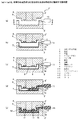
図1は、本発明の実施例1に係る成形方法の工程を模式的に説明する説明図である。なお、この図1では、本発明の特徴を理解し易くするために、その形状や寸法等は実際のものとは異なって示されている。また、以下では、リブが形成されて凹凸を有する第1面と、その反対側の第2面の両面に塗膜を備える成形品を成形する方法について説明しており、特に、成形型としてZAS型を用い、且つ、第2面における塗膜の形成を加飾シートを成形一体化することによって行う場合を例に挙げている。しかし、本発明はこれに何ら限定されるものではなく、前記基本的な構成を具備し、本発明の課題を解決することができるものであれば多様な変更が可能である。例えば、成形型としてはZAS型の代わりに樹脂型を用いることができるし、また第2面における塗膜の形成を、型内塗装、後塗装、又はその他の塗装方法を用いて行うことも可能である。 FIG. 1 is an explanatory view schematically illustrating the steps of the molding method according to Example 1 of the present invention. In FIG. 1, in order to facilitate understanding of the features of the present invention, the shape, dimensions, and the like are shown differently from the actual ones. In the following, a method for forming a molded product having a coating film on both sides of the first surface having ribs and having irregularities and the second surface on the opposite side is described. The case where the formation of the coating film on the second surface is performed by molding and integrating the decorative sheet is described as an example. However, the present invention is not limited to this, and various modifications are possible as long as they have the above basic configuration and can solve the problems of the present invention. For example, a resin mold can be used as the mold instead of the ZAS mold, and the coating on the second surface can be formed using in-mold coating, post-coating, or other coating methods. It is.
先ず、本実施例1に係る成形方法は、図1の(a)に示したように、成形品10の第1面を成形可能なキャビティ面を有する上型2と、第2面を成形可能なキャビティ面を有する下型3とからなるZAS型1を作製して準備する。本実施例1では、第1面に複数のリブ11を有し、且つ、周縁部にフランジ12を有する成形品10を成形可能なように、上型2及び下型3のキャビティ面がそれぞれ所定の形状に形成されている。
First, in the molding method according to the first embodiment, as shown in FIG. 1A, the
また、上型2には、成形材料であるウレタンウレア樹脂の原料を調製するミキシングヘッド13が配されており、ミキシングヘッド13で調製したウレタンウレア樹脂の混合原料がキャビティ8内に直接注入されるように構成されている。特に本実施例1では、成形材料として、原料を混合してからの硬化時間が短いウレタンウレア樹脂を用いるため、キャビティ8内に原料を迅速に充填可能なように、上型2の略中央部にミキシングヘッド13が配されている。
Further, the
更に、上型2には、混合原料をキャビティ8内に注入した際に、同キャビティ8内に存在していた気体を排出するためのベント溝5が形成されており、また、成形後に成形品10を突出してその取り出しを円滑に行うためのエジェクタピン4が配されている。前記ベント溝5は、混合原料をキャビティ8内に流動させたときの下流側の末端でパーティングラインに沿った位置に設けられている。なお、このような形状を有する上型2及び下型3は、従来から用いられている方法によって容易に作製することが可能である。また、本実施例1では、必要に応じてエジェクタピン4の隙間から気体を抜くことが可能なように上型2を構成することも可能である。
Further, the
上記のような所定形状の上型2と下型3とを作製した後、それぞれのキャビティ面に離型剤を塗布する。本実施例1では成形型が亜鉛合金製であるため、ウレタンウレア樹脂よりも融点が高い離型剤を用いることができる。
After the
次に、図1の(b)に示したように、成形時に型内塗装により成形品10の第1面に塗膜を形成するために、前記で作製した上型2のキャビティ面に塗料6をスプレーで塗布する。このとき、前記塗料6として、脂肪族ポリウレタン樹脂塗料を用いることにより、成形品の第1面に耐候性に優れた塗膜を形成することが可能となる。また、脂肪族ポリウレタン樹脂塗料に顔料等を含有させることによって、塗膜に様々な色彩を付与することも可能となる。
Next, as shown in FIG. 1B, in order to form a coating film on the first surface of the molded
また、上型2のキャビティ面に塗料6を塗布するとともに、成形品10の第2面にも塗膜を形成するために、下型3にはそのキャビティ面の形状に沿うように予備賦形した加飾シート7をセットする。この加飾シート7は、予め所定の加飾が施されている。なお、加飾シート7を予備賦形する方法は特に限定されず、従来から一般的に行われている方法を用いることができる。
Further, in order to apply the
例えば、下型3に真空吸引孔(不図示)を設けるとともに、同真空吸引孔に吸引ポンプ(不図示)等を接続しておき、加熱して軟化させた熱可塑性の加飾シート7を下型3に載置する。その後、吸引ポンプ等で真空吸引孔を通じて吸引することにより、軟化した加飾シート7を下型3に吸引密着させて冷却する。これにより、加飾シート7を下型3のキャビティ面に沿った形状に賦形した状態で下型3にセットすることができる。
For example, a vacuum suction hole (not shown) is provided in the
この下型3にセットする加飾シート7の材質は特に限定されないが、例えば、塩化ビニル樹脂、メタクリル樹脂、ABS樹脂、AES樹脂、及びウレタン樹脂のうちから選択される何れか1つ又は2つ以上を組み合わせたものからなる加飾シートを用いることができる。これにより、優れた耐候性や光沢度を有する塗膜を成形品10の第2面に形成でき、成形品10の品質を向上させることができる。また、加飾シート7に着色、各種柄印刷、金属蒸着等の処理を施すこともでき、それによって、成形品10の第2面に様々なデザインを付与することも可能となる。
The material of the
上述のように上型2のキャビティ面に脂肪族ポリウレタン樹脂塗料6を塗布し、また、下型3に加飾シート7をセットした後、上型2と下型3とを型締する(図1の(c))。これにより、上型2と下型3との間には、所定形状のキャビティ8が形成される。
As described above, the aliphatic
その後、成形材料であるウレタンウレア樹脂の原料をミキシングヘッド13で調製する。原料の調製は、先ず、ポリオールと、ポリアミンと、水とをそれぞれ所定量で混合することによって第1混合原料を作製する。このとき、必要に応じて、第1混合原料に、整泡剤、触媒、着色剤、及び窒素ガス等を適宜混入することもできる。
Thereafter, a raw material of urethane urea resin as a molding material is prepared by the mixing
次に、作製した前記第1混合原料と所定量のポリイソシアネートとをミキシングヘッド13内に導入して混合することによって、第2混合原料9を調製する。このとき、第1混合原料とポリイソシアネートとが混合されることによりウレタンウレア樹脂の重合反応及び硬化が始まるため、第2混合原料9を調製すると同時に、同第2混合原料9をミキシングヘッド13から金型1のキャビティ8内に高速で注入する(図1の(d))。
Next, the produced first mixed raw material and a predetermined amount of polyisocyanate are introduced into the mixing
また、第2混合原料9を調製する際には、ウレタンウレア樹脂の反応において、ウレタン反応とウレア反応との割合がウレタン反応:ウレア反応=(3〜5):(7〜5)となるように、好ましくはウレタン反応:ウレア反応=4:6となるように混合原料の成分比を調整する。 Moreover, when preparing the 2nd mixing raw material 9, in the reaction of urethane urea resin, the ratio of urethane reaction and urea reaction will be urethane reaction: urea reaction = (3-5) :( 7-5). In addition, the component ratio of the mixed raw material is preferably adjusted so that urethane reaction: urea reaction = 4: 6.
このとき、ウレア反応の割合が7割を超えて大きくなると、ウレタンウレア樹脂の硬化時間が短くなり過ぎるため、作業機械の外装部材に用いられるような大型の成形品を成形する場合、キャビティ8内に第2混合原料9を十分に充填できず、所定形状の成形品を得ることが困難になることが考えられる。また、ウレア反応の割合が大きくなり過ぎると、得られる成形品の曲げ強度や曲げ弾性率が低くなり、作業機械の外装部材に求められる強度や剛性が得られなくなる恐れもある。 At this time, if the ratio of the urea reaction exceeds 70%, the curing time of the urethane urea resin becomes too short. Therefore, when molding a large molded product used for an exterior member of a work machine, In addition, the second mixed raw material 9 cannot be sufficiently filled, and it may be difficult to obtain a molded product having a predetermined shape. Moreover, when the ratio of the urea reaction becomes too large, the bending strength and bending elastic modulus of the obtained molded product are lowered, and the strength and rigidity required for the exterior member of the work machine may not be obtained.
一方、ウレア反応の割合が5割よりも小さくなると、成形品の高温強度が低くなるなどの不具合が生じる恐れがある。なお、本実施例1では、ウレタン反応:ウレア反応=4:6となるように第2混合原料9を調製してZAS型1のキャビティ8内に高速で注入した。この場合、ポリイソシアネートを混合してからのウレタンウレア樹脂の硬化時間は約5秒である。
On the other hand, when the ratio of the urea reaction is less than 50%, there is a risk that problems such as a decrease in the high-temperature strength of the molded product may occur. In Example 1, the second mixed raw material 9 was prepared so as to be urethane reaction: urea reaction = 4: 6 and injected into the
ここで、ポリオールとしては、例えばポリエーテルポリオール、ポリエステルポリオール、ポリカーボネートポリオール、ポリカプロラクトンポリオール、エポキシポリオール、アクリルポリオールなどを用いることができる。また、ポリアミンとしては、例えば変性脂肪族ポリアミン、変性脂環式ポリアミン、変性芳香族ポリアミン、脂肪族ポリアミン、脂環式ポリアミン、芳香族ポリアミンなどを用いることができる。更に、ポリイソシアネートとしては、例えば脂肪族ポリイソシアネート、脂環式ポリイソシアネート、芳香族ポリイソシアネートなどを用いることができる。 Here, as a polyol, polyether polyol, polyester polyol, polycarbonate polyol, polycaprolactone polyol, epoxy polyol, acrylic polyol etc. can be used, for example. Examples of polyamines that can be used include modified aliphatic polyamines, modified alicyclic polyamines, modified aromatic polyamines, aliphatic polyamines, alicyclic polyamines, and aromatic polyamines. Furthermore, as a polyisocyanate, aliphatic polyisocyanate, alicyclic polyisocyanate, aromatic polyisocyanate, etc. can be used, for example.
そして、ミキシングヘッド13からキャビティ8の末端に向けて第2混合原料9を流動させてキャビティ8内に第2混合原料9を充填し、キャビティ8内でウレタンウレア樹脂を反応させて硬化させる。これにより、ウレタンウレア樹脂からなる成形品10が成形される(図1の(e))。このとき、ウレタン反応ではガスが発生するものの、その発生したガスはウレタンウレア樹脂が硬化するまでの間にウレア成分内に取り込まれることにより、成形品全体に微細な気泡が形成されて、成形品の第1面側では従来のようなボイドの形成を防ぐことができると考えられる。
Then, the second mixed raw material 9 is caused to flow from the mixing
従って、上述のようにウレタンウレア樹脂のRIM成形を行えば、成形品10の第1面にはボイドが形成されないため、同第1面に型内塗装を行っても、前述の図5に示したような塗装不良は生じず、第1面に塗膜6’を安定して形成することができる。また更に、その後に行うZAS型の清掃も容易となる。
Therefore, if RIM molding of urethane urea resin is performed as described above, voids are not formed on the first surface of the molded
また、ウレタンウレア樹脂は、重合反応が起こると同時に微発泡する。例えば、RIM法により非発泡タイプの合成樹脂(例えば、ポリウレタン)を成形した場合、成形品のリブやボスを形成した部位の裏側にヒケが発生するという問題があるが、本実施例1では、成形時にウレタンウレア樹脂の微発泡によりヒケの発生を防止することができ、所定形状の成形品10を安定して形成することができる。
Further, the urethane urea resin is slightly foamed simultaneously with the polymerization reaction. For example, when a non-foamed type synthetic resin (for example, polyurethane) is molded by the RIM method, there is a problem that sink marks occur on the back side of the part where the ribs and bosses of the molded product are formed. The generation of sink marks can be prevented by the fine foaming of the urethane urea resin during molding, and the molded
ウレタンウレア樹脂が金型1内で硬化したら、型開きをしてエジェクタピン4で成形品10を突き出すことにより、内側表面となる第1面にリブを有し、且つ、脂肪族ポリウレタン樹脂塗料により形成された塗膜6’を備えており、また、外側表面となる第2面に加飾シート7が成形一体化されている外観品質に優れた成形品10を得ることができる。
When the urethane urea resin is cured in the
即ち、従来では凹凸を有する内側表面となる第1面と、外側表面となる第2面とに塗膜を形成する場合、第1面に均一な塗膜を安定して形成するためには、成形後にボイドの補修作業を行って後塗装を行わなければならなかったのに対し、上述のような本実施例1の方法であれば、ボイドの補修作業が不要となり、後塗装よりも工程数が少なく簡便な型内塗装で第1面に均一な塗膜を安定して形成することができる。このため、従来の方法に比べて、作業工程の簡略化やコストダウンを達成することができ、低コストの成形品を提供することができる。 That is, when a coating film is conventionally formed on the first surface serving as the inner surface having irregularities and the second surface serving as the outer surface, in order to stably form a uniform coating film on the first surface, In contrast to the fact that after the molding, the void must be repaired and post-coating had to be carried out, whereas with the method of the first embodiment as described above, void repairing work was not necessary and the number of processes was more than post-coating. A uniform coating film can be stably formed on the first surface by simple and in-mold coating. For this reason, compared with the conventional method, the simplification and cost reduction of a work process can be achieved, and a low-cost molded product can be provided.
また、上述のようにして得られた成形品10は、0.4g/cm3以上1.0g/cm3以下の密度を有し、その内部には気泡が形成されている。本実施例1において、成形品10に形成された気泡の平均直径は10μm以上40μm以下であり、また、各気泡の直径は4μm以上100μm以下である。このような密度及び気泡サイズを有する成形品10であれば、例えば非発泡タイプのポリウレタン成形品に比べて軽量となり、また、外装部材としての十分な強度を有している。
In addition, the molded
更に、本実施例1で得られた成形品10は、外装部材として用いた際にその防音効果を高めるために、成形品10の第1面に吸音材を貼付することが可能である。成形品10における吸音材の貼付領域は特に限定されないが、例えばリブを除いた領域に吸音材を貼付することが好ましく、例えばその貼付領域の形状に合わせて吸音材を裁断した後、同吸音材を接着剤等を用いて成形品に貼り付ける。なお、吸音材は、従来と同様のものを用いることが可能であり、例えばポリウレタンフォームやポリエチレンフォーム等からなる吸音材が好適に用いられる。
Further, when the molded
このとき、本実施例1では、前述のように成形時に離型剤として融点が高いものを用いているため、成形品を金型から取り出した際に、離型剤を金型1に残存させて、成形品10に付着することを防ぐことができる。従って、成形品10に吸音材を貼付するときに、成形品10から離型剤を除去する作業を行わずに済み、吸音材の貼付を容易に行うことができる。このようにして製造された成形品は、防音効果にも優れているため、作業機械のエンジングリルやマシンキャブ等として非常に好適に適用することができる。
At this time, in Example 1, since a mold having a high melting point is used as a mold release agent at the time of molding as described above, the mold release agent is left in the
なお、本実施例1では、成形品10の第2面に形成する塗膜は、加飾シート7を成形品10に成形一体化することによって形成されているが、前述のように、本発明はこれに限定されるものではない。例えば、成形品の第2面に形成する塗膜は、第1面に形成する塗膜と同様に型内塗装によって形成することもできる。このように第2面に型内塗装を行う場合、加飾シートの作製や予備賦形を行わずに、下型のキャビティ面に塗料をスプレー等で塗布することによって塗膜を形成することができるため、短時間でより簡便に成形品を得ることが可能となる。なお、下型のキャビティ面に塗布する塗料は特に限定されないが、例えば第1面に形成する塗膜と同様に脂肪族ポリウレタン樹脂塗料を用いて、耐候性に優れた塗膜を第2面に形成することができる。
In Example 1, the coating film formed on the second surface of the molded
またその他に、成形時には成形品の第1面のみに型内塗装によって塗膜を形成しておき、その後に第2面のみに別途に塗装を施して塗膜を形成することも可能である。本発明では、前述のように成形品にヒケが発生することを防止できるため、後塗装によって第2面に塗膜を形成する場合でも、成形後に第2面の補修等を行わずに塗装を簡便に行うことが可能となる。 In addition, at the time of molding, it is also possible to form a coating film only on the first surface of the molded product by in-mold coating, and then separately coat only the second surface to form the coating film. In the present invention, since it is possible to prevent the occurrence of sink marks on the molded product as described above, even when a coating film is formed on the second surface by post-coating, coating is performed without performing repair or the like on the second surface after molding. It becomes possible to carry out simply.
次に、本発明の実施例2に係る成形方法について説明する、ここで、図2は、本実施例2に係る成形方法の工程を模式的に説明する説明図であり、図3は、図2(a)に示したIII−III線の矢視断面図である。なお、図3では、ミキシングヘッド、スプルー、ベント溝の配設位置を理解し易く示すため、上型のキャビティ面の形状やエジェクタピンの図示を省略している。また、本実施例2において、前記実施例1で説明した部材と同様の構成を有する部材については、同じ符号を用いて表している。このような同じ符号で表された部材については、前記実施例1と同様であるため、その説明を省略する。 Next, the molding method according to Example 2 of the present invention will be described. Here, FIG. 2 is an explanatory diagram schematically illustrating the steps of the molding method according to Example 2, and FIG. It is arrow sectional drawing of the III-III line shown to 2 (a). In FIG. 3, the shape of the upper cavity surface and the ejector pins are not shown in order to facilitate understanding of the arrangement positions of the mixing head, sprue, and vent groove. In the second embodiment, members having the same configuration as the members described in the first embodiment are denoted by the same reference numerals. About the member represented with the same code | symbol, since it is the same as that of the said Example 1, the description is abbreviate | omitted.
本実施例2に係る成形方法は、図2の(a)に示したように、成形品10の第1面を成形可能なキャビティ面を有する上型2’と、第2面を成形可能なキャビティ面を有する下型3’とからなるZAS型1’を作製して準備する。本実施例2で用いる上型2’及び下型3’では、ウレタンウレア樹脂の混合原料をキャビティ8内に注入するためのスプルー14、ランナー15、及びゲート16がパーティングラインに沿って設けられており、また、スプルー14にミキシングヘッド13のノズルが接続されるように構成されている。
In the molding method according to the second embodiment, as shown in FIG. 2A, the
前記スプルー14は、図3に示したように、ランナー15に向けて幅方向の寸法が漸次拡がるように形成されており、またランナー15及びゲート16は、キャビティ8の幅方向の長さ全体に渡って直線的に形成されている。なお、ウレタンウレア樹脂は、前述のように原料を混合してからの硬化時間が短いため、スプルー14、ランナー15、及びゲート16を形成する位置は非常に重要であり、これらの形成位置は、キャビティ8の形状や混合原料の流動距離などを勘案して決定される。
As shown in FIG. 3, the
また、上型2には、気体を排出するためのベント溝5や、成形品10の取り出しを円滑に行うためのエジェクタピン4が配されている。ベント溝5は、ゲート16から注入された混合原料をキャビティ8内に流動させたときの下流側(ゲート16とは反対側の端部)でパーティングラインに沿った位置に形成されている。
Further, the
上記のような所定形状の上型2’と下型3’とを作製した後、それぞれのキャビティ面に離型剤を塗布する。次に、図2の(b)に示したように、上型2のキャビティ面に塗料6をスプレーで塗布し、また下型3のキャビティ面に予備賦形した加飾シート7をセットし、その後、上型2と下型3とを型締する(図2の(c))。これにより、上型2と下型3との間には、所定形状のキャビティ8が形成される。
After the upper mold 2 'and the lower mold 3' having the predetermined shapes as described above are manufactured, a release agent is applied to each cavity surface. Next, as shown in FIG. 2 (b),
その後、成形材料であるウレタンウレア樹脂の第2混合原料9をミキシングヘッド13で調製すると同時に、その第2混合原料9をミキシングヘッド13から、スプルー14、ランナー15、及びゲート16を介して成形型1’のキャビティ8内に高速で注入する(図2の(d))。このとき、ゲート16から注入された第2混合原料9は、ゲート16側から、その反対側の端部に向けてキャビティ8内に充填されていき、キャビティ8内でウレタンウレア樹脂を反応させて硬化させる。これにより、ウレタンウレア樹脂からなる成形品10が成形される(図2の(e))。
Thereafter, the second mixed raw material 9 of urethane urea resin, which is a molding material, is prepared by the mixing
そして、ウレタンウレア樹脂が金型1’内で硬化した後、型開きをしてエジェクタピン4で成形品10を突き出すことにより、内側表面となる第1面にリブを有し、且つ、脂肪族ポリウレタン樹脂塗料により形成された塗膜6’を備えており、また、外側表面となる第2面に加飾シート7が成形一体化されている外観品質に優れた成形品10を得ることができる。以上のような本実施例2に係るウレタンウレア樹脂のRIM成形を行うことによっても、前記実施例1と同様の作用効果を得ることができる。
And after urethane urea resin hardens | cures in metal mold | die 1 ', it has a rib in the 1st surface used as an inner surface by opening a mold | die and projecting the molded
本発明は、建設機械、農業機械、及び林業車両等の作業機械におけるエンジングリルやマシンキャブ等として用いられる成形品を成形する際に有効に適用することができる。 INDUSTRIAL APPLICABILITY The present invention can be effectively applied when molding a molded product used as an engine grill, a machine cab, or the like in a work machine such as a construction machine, an agricultural machine, or a forestry vehicle.
1,1’ 金型(ZAS型)
2,2’ 上型
3,3’ 下型
4 エジェクタピン
5 ベント溝
6 塗料
6’ 塗膜
7 加飾シート
8 キャビティ
9 第2混合原料
10 成形品
13 ミキシングヘッド
14 スプルー
15 ランナー
16 ゲート
21 成形体
22 内側表面
23 リブ
24 ボイド
31 上型
32 下型
33 加飾シート
34 成形品
35 塗料
35’ 塗膜
36 ボイド
1,1 'mold (ZAS type)
2, 2 '
Claims (13)
前記第1面を成形可能なキャビティ面を備えた上型(2,2')と、前記第2面を成形可能なキャビティ面を備えた下型(3,3')とを作製すること、
前記上型(2,2')のキャビティ面に塗料(6)を塗布すること、
前記下型(3,3')と前記塗料(6)を塗布した上型(2,2')とを型締すること、
ポリオールと、ポリアミンと、水とを混合し、ウレタンウレア樹脂のウレタン反応とウレア反応との割合を、ウレタン反応:ウレア反応=(3〜5):(7〜5)となるように成分比を調整して第1混合原料を調製すること、
前記第1混合原料にポリイソシアネートを混合して第2混合原料(9)を調製すると同時に、同第2混合原料(9)を前記上型(2,2')と前記下型(3,3')との間に形成されたキャビティ(8)内に注入して、反応射出成形法によりウレタンウレア樹脂からなる成形品(10)を発泡成形し、前記塗料(6)を成形品(10)に転写すること、
を含んでなることを特徴とする成形方法。 Molded product (10) used as an exterior member for engine grills, etc. of work machines, and having a coating film on a first surface serving as an inner surface having irregularities such as ribs and bosses, and a second surface serving as an outer surface A method of molding
Producing an upper die (2, 2 ') having a cavity surface capable of forming the first surface and a lower die (3, 3') having a cavity surface capable of forming the second surface;
Applying paint (6) to the cavity surface of the upper mold (2, 2 ');
Clamping the lower mold (3, 3 ') and the upper mold (2, 2') coated with the paint (6);
Polyol, polyamine, and water are mixed , and the ratio of the urethane reaction and the urea reaction of the urethane urea resin is adjusted so that the ratio of the components is urethane reaction: urea reaction = (3-5) :( 7-5). Adjusting to prepare the first mixed raw material,
The second mixed raw material (9) is prepared by mixing the first mixed raw material with polyisocyanate, and at the same time, the second mixed raw material (9) is mixed with the upper mold (2,2 ') and the lower mold (3,3). ') Is injected into the cavity (8) formed between the two and foamed molding (10) made of urethane urea resin by a reaction injection molding method, and the paint (6) is molded into the molded product (10). To transcribe to,
A molding method comprising:
前記下型(3,3')と前記上型(2,2')とを型締する前に、同下型(3,3')のキャビティ面に所定形状に予備賦形した加飾シート(7)を配すること
を含んでなることを特徴とする請求項1記載の成形方法。 In order to form the coating film on the second surface,
A decorative sheet pre-shaped into a predetermined shape on the cavity surface of the lower mold (3, 3 ') before clamping the lower mold (3, 3') and the upper mold (2, 2 ') molding method according to claim 1, characterized in that it comprises a placing (7).
前記下型(3,3')と前記上型(2,2')とを型締する前に、同下型(3,3')のキャビティ面に塗料を塗布すること
を含んでなることを特徴とする請求項1記載の成形方法。 In order to form the coating film on the second surface,
Before the lower mold (3, 3 ') and the upper mold (2, 2') are clamped, comprising applying a paint to the cavity surface of the lower mold (3, 3 ') The molding method according to claim 1 .
前記反応射出成形を行った後に、得られた成形品(10)の第2面側に塗装を施すこと
を含んでなることを特徴とする請求項1記載の成形方法。 In order to form the coating film on the second surface,
Wherein after the reaction injection molding, the resulting molded method according to claim 1, characterized in that it comprises that the coating applied to the second surface of the molded article (10).
Priority Applications (1)
| Application Number | Priority Date | Filing Date | Title |
|---|---|---|---|
| JP2006085444A JP4762020B2 (en) | 2006-03-27 | 2006-03-27 | Molding method and molded product |
Applications Claiming Priority (1)
| Application Number | Priority Date | Filing Date | Title |
|---|---|---|---|
| JP2006085444A JP4762020B2 (en) | 2006-03-27 | 2006-03-27 | Molding method and molded product |
Publications (2)
| Publication Number | Publication Date |
|---|---|
| JP2007260939A JP2007260939A (en) | 2007-10-11 |
| JP4762020B2 true JP4762020B2 (en) | 2011-08-31 |
Family
ID=38634426
Family Applications (1)
| Application Number | Title | Priority Date | Filing Date |
|---|---|---|---|
| JP2006085444A Expired - Fee Related JP4762020B2 (en) | 2006-03-27 | 2006-03-27 | Molding method and molded product |
Country Status (1)
| Country | Link |
|---|---|
| JP (1) | JP4762020B2 (en) |
Families Citing this family (13)
| Publication number | Priority date | Publication date | Assignee | Title |
|---|---|---|---|---|
| CN101061759B (en) | 2004-07-21 | 2011-05-25 | 斯蒂尔瑞弗系统有限公司 | A programmable radio frequency waveform generator for a synchrocyclotron |
| EP2389983B1 (en) | 2005-11-18 | 2016-05-25 | Mevion Medical Systems, Inc. | Charged particle radiation therapy |
| US8003964B2 (en) | 2007-10-11 | 2011-08-23 | Still River Systems Incorporated | Applying a particle beam to a patient |
| US8581523B2 (en) | 2007-11-30 | 2013-11-12 | Mevion Medical Systems, Inc. | Interrupted particle source |
| US8933650B2 (en) | 2007-11-30 | 2015-01-13 | Mevion Medical Systems, Inc. | Matching a resonant frequency of a resonant cavity to a frequency of an input voltage |
| CN103228414B (en) | 2010-09-30 | 2015-12-16 | 陶氏环球技术有限责任公司 | The container minimizing the defect in reactive polyurethane flow process is modified |
| WO2014052721A1 (en) | 2012-09-28 | 2014-04-03 | Mevion Medical Systems, Inc. | Control system for a particle accelerator |
| EP3581243A1 (en) | 2012-09-28 | 2019-12-18 | Mevion Medical Systems, Inc. | Controlling particle therapy |
| WO2014052709A2 (en) | 2012-09-28 | 2014-04-03 | Mevion Medical Systems, Inc. | Controlling intensity of a particle beam |
| KR101536399B1 (en) * | 2013-05-03 | 2015-07-14 | 한국기계연구원 | In mold coating device |
| EP3049151B1 (en) | 2013-09-27 | 2019-12-25 | Mevion Medical Systems, Inc. | Particle beam scanning |
| CN105034242B (en) * | 2015-08-28 | 2018-12-04 | 武汉泰宇汽车零部件有限公司 | The manufacturing method of foaming mould and high-pressure oil pump sound insulation the cover |
| JP6839325B1 (en) * | 2019-09-02 | 2021-03-03 | 日本碍子株式会社 | Manufacturing method of molded product |
Family Cites Families (4)
| Publication number | Priority date | Publication date | Assignee | Title |
|---|---|---|---|---|
| JPS6071224A (en) * | 1983-09-27 | 1985-04-23 | Mazda Motor Corp | Coating method for resin molded article having deep- drawn portion |
| JPH02209961A (en) * | 1986-09-16 | 1990-08-21 | Sumitomo Bayer Urethane Kk | Production of molded article of polyurethane/polyurea |
| JPH0253818A (en) * | 1988-08-18 | 1990-02-22 | Mitsui Toatsu Chem Inc | Production of polyurethane-polyurea composition |
| JP2005081737A (en) * | 2003-09-09 | 2005-03-31 | Puroto Giken:Kk | Reaction injection-molded article and its manufacturing method |
-
2006
- 2006-03-27 JP JP2006085444A patent/JP4762020B2/en not_active Expired - Fee Related
Also Published As
| Publication number | Publication date |
|---|---|
| JP2007260939A (en) | 2007-10-11 |
Similar Documents
| Publication | Publication Date | Title |
|---|---|---|
| JP4762020B2 (en) | Molding method and molded product | |
| JP2007503331A (en) | Manufacturing method of composite trim parts for automobile interior | |
| JP6356668B2 (en) | Method for manufacturing said flexible skin having at least one insert bonded to the flexible skin | |
| HUE027260T2 (en) | Method and mould for producing a panel assembly | |
| MX2008002554A (en) | Panel-like laminate and a skin for manufacturing such laminate. | |
| JP2004168064A (en) | Manufacturing method for molded body fixed and bonded to roughened or structured molded skin, and device for carrying out the method | |
| JP2013517983A (en) | Roof panel and method for manufacturing the roof panel | |
| KR20180061599A (en) | Car interior material manufacturing apparatus | |
| US6171543B1 (en) | Rocker panel construction | |
| JP2007502226A (en) | Manufacturing method for reinforced plastic products | |
| JP2001150484A (en) | Method for producing window made of resin | |
| JP5357512B2 (en) | Manufacturing method of wooden decorative board | |
| CN107914357A (en) | A kind of preparation method of bumper | |
| JPH081711A (en) | Manufacture of resin molding having hollow part | |
| JP5421625B2 (en) | Equipment for manufacturing fiber reinforced resin parts | |
| JP6609143B2 (en) | Manufacturing method of fiber-reinforced resin molded body and molded body thereof | |
| JP2570164B2 (en) | Window and its integral molding method | |
| US20040168755A1 (en) | Method of making three-dimensional design | |
| JPS5971838A (en) | Manufacture of color bumper cover with decoration | |
| JP3996547B2 (en) | Golf club head and manufacturing method thereof | |
| JP7343361B2 (en) | Manufacturing method for resin molded products | |
| JPH04201424A (en) | Hollow non-rigid air spoiler-shaped body and forming method thereof | |
| CN107775874A (en) | Composite board forming method and composite board | |
| US8337745B2 (en) | Integral molten evacuation channel | |
| JP2002036264A (en) | Double-layered molded article and method for manufacturing the same |
Legal Events
| Date | Code | Title | Description |
|---|---|---|---|
| A621 | Written request for application examination |
Free format text: JAPANESE INTERMEDIATE CODE: A621 Effective date: 20081029 |
|
| A977 | Report on retrieval |
Free format text: JAPANESE INTERMEDIATE CODE: A971007 Effective date: 20110127 |
|
| A131 | Notification of reasons for refusal |
Free format text: JAPANESE INTERMEDIATE CODE: A131 Effective date: 20110201 |
|
| A521 | Request for written amendment filed |
Free format text: JAPANESE INTERMEDIATE CODE: A523 Effective date: 20110331 |
|
| TRDD | Decision of grant or rejection written | ||
| A01 | Written decision to grant a patent or to grant a registration (utility model) |
Free format text: JAPANESE INTERMEDIATE CODE: A01 Effective date: 20110607 |
|
| A01 | Written decision to grant a patent or to grant a registration (utility model) |
Free format text: JAPANESE INTERMEDIATE CODE: A01 |
|
| A61 | First payment of annual fees (during grant procedure) |
Free format text: JAPANESE INTERMEDIATE CODE: A61 Effective date: 20110607 |
|
| FPAY | Renewal fee payment (event date is renewal date of database) |
Free format text: PAYMENT UNTIL: 20140617 Year of fee payment: 3 |
|
| R150 | Certificate of patent or registration of utility model |
Ref document number: 4762020 Country of ref document: JP Free format text: JAPANESE INTERMEDIATE CODE: R150 Free format text: JAPANESE INTERMEDIATE CODE: R150 |
|
| LAPS | Cancellation because of no payment of annual fees |