JP4762007B2 - Relay device, communication terminal, and communication system - Google Patents
Relay device, communication terminal, and communication system Download PDFInfo
- Publication number
- JP4762007B2 JP4762007B2 JP2006058518A JP2006058518A JP4762007B2 JP 4762007 B2 JP4762007 B2 JP 4762007B2 JP 2006058518 A JP2006058518 A JP 2006058518A JP 2006058518 A JP2006058518 A JP 2006058518A JP 4762007 B2 JP4762007 B2 JP 4762007B2
- Authority
- JP
- Japan
- Prior art keywords
- communication terminal
- frame
- transmission
- signal
- communication
- Prior art date
- Legal status (The legal status is an assumption and is not a legal conclusion. Google has not performed a legal analysis and makes no representation as to the accuracy of the status listed.)
- Expired - Fee Related
Links
Images


Classifications
-
- H—ELECTRICITY
- H04—ELECTRIC COMMUNICATION TECHNIQUE
- H04B—TRANSMISSION
- H04B7/00—Radio transmission systems, i.e. using radiation field
- H04B7/14—Relay systems
- H04B7/15—Active relay systems
- H04B7/155—Ground-based stations
- H04B7/15528—Control of operation parameters of a relay station to exploit the physical medium
-
- H—ELECTRICITY
- H04—ELECTRIC COMMUNICATION TECHNIQUE
- H04W—WIRELESS COMMUNICATION NETWORKS
- H04W52/00—Power management, e.g. Transmission Power Control [TPC] or power classes
- H04W52/02—Power saving arrangements
- H04W52/0209—Power saving arrangements in terminal devices
- H04W52/0225—Power saving arrangements in terminal devices using monitoring of external events, e.g. the presence of a signal
- H04W52/0229—Power saving arrangements in terminal devices using monitoring of external events, e.g. the presence of a signal where the received signal is a wanted signal
-
- H—ELECTRICITY
- H04—ELECTRIC COMMUNICATION TECHNIQUE
- H04W—WIRELESS COMMUNICATION NETWORKS
- H04W48/00—Access restriction; Network selection; Access point selection
- H04W48/08—Access restriction or access information delivery, e.g. discovery data delivery
-
- H—ELECTRICITY
- H04—ELECTRIC COMMUNICATION TECHNIQUE
- H04W—WIRELESS COMMUNICATION NETWORKS
- H04W74/00—Wireless channel access
- H04W74/08—Non-scheduled access, e.g. ALOHA
- H04W74/0808—Non-scheduled access, e.g. ALOHA using carrier sensing, e.g. carrier sense multiple access [CSMA]
- H04W74/0816—Non-scheduled access, e.g. ALOHA using carrier sensing, e.g. carrier sense multiple access [CSMA] with collision avoidance
-
- H—ELECTRICITY
- H04—ELECTRIC COMMUNICATION TECHNIQUE
- H04W—WIRELESS COMMUNICATION NETWORKS
- H04W88/00—Devices specially adapted for wireless communication networks, e.g. terminals, base stations or access point devices
- H04W88/02—Terminal devices
- H04W88/04—Terminal devices adapted for relaying to or from another terminal or user
-
- Y—GENERAL TAGGING OF NEW TECHNOLOGICAL DEVELOPMENTS; GENERAL TAGGING OF CROSS-SECTIONAL TECHNOLOGIES SPANNING OVER SEVERAL SECTIONS OF THE IPC; TECHNICAL SUBJECTS COVERED BY FORMER USPC CROSS-REFERENCE ART COLLECTIONS [XRACs] AND DIGESTS
- Y02—TECHNOLOGIES OR APPLICATIONS FOR MITIGATION OR ADAPTATION AGAINST CLIMATE CHANGE
- Y02D—CLIMATE CHANGE MITIGATION TECHNOLOGIES IN INFORMATION AND COMMUNICATION TECHNOLOGIES [ICT], I.E. INFORMATION AND COMMUNICATION TECHNOLOGIES AIMING AT THE REDUCTION OF THEIR OWN ENERGY USE
- Y02D30/00—Reducing energy consumption in communication networks
- Y02D30/70—Reducing energy consumption in communication networks in wireless communication networks
Landscapes
- Engineering & Computer Science (AREA)
- Computer Networks & Wireless Communication (AREA)
- Signal Processing (AREA)
- Mobile Radio Communication Systems (AREA)
- Small-Scale Networks (AREA)
Abstract
Description
本発明は、無線LAN(Local Area Network)の通信システムに関し、特に、当該通信システム上の通信端末と、通信端末間の通信を中継する中継装置に関する。 The present invention relates to a wireless LAN (Local Area Network) communication system, and more particularly, to a communication terminal on the communication system and a relay device that relays communication between the communication terminals.
従来、無線LANネットワークにおいて、インフラストラクチャモードと呼ばれる通信モードがあり、このインフラストラクチャモードでは、ネットワークを統括する特定の中継装置(以下、アクセスポイントと呼ぶ)を介して複数の通信端末間が通信を行うようになっている。
無線LAN規格の代表的なものとしては、IEEE(Institute of Electrical and Electronic Engineers)802.11規格がある(非特許文献1を参照)。
Conventionally, a wireless LAN network has a communication mode called an infrastructure mode. In this infrastructure mode, a plurality of communication terminals communicate with each other via a specific relay device (hereinafter referred to as an access point) that controls the network. To do.
A typical wireless LAN standard is the IEEE (Institute of Electrical and Electronic Engineers) 802.11 standard (see Non-Patent Document 1).
例えば、このIEEE802.11規格では、インフラストラクチャモードで通信を行う場合、アクセスポイントは、ネットワーク内の各通信端末に対してビーコン信号を送信している。このビーコン信号には、アクセスポイント自身の識別子であるSSID(Service Set Identifier)や、アクセスポイントがサポートしている通信速度に関する情報などの管理情報の他、各通信端末宛のデータがアクセスポイントに蓄積されていないかを示す情報などが含まれている。 For example, in the IEEE 802.11 standard, when communication is performed in the infrastructure mode, the access point transmits a beacon signal to each communication terminal in the network. In this beacon signal, in addition to management information such as SSID (Service Set Identifier), which is the identifier of the access point itself, and information on the communication speed supported by the access point, data addressed to each communication terminal is stored in the access point. It includes information that indicates whether or not
各通信端末はビーコン信号を受信することで、常時データの送受信に備えることができるようになっている。
また、各通信端末は、自端末内のバッテリの消費電力を抑えるための「パワーセーブモード」に設定されることがある。
パワーセーブモードに設定された通信端末は、アクセスポイントからのビーコン信号を受信するタイミングでのみ受信部を駆動させてそれ以外の間は駆動させないことによって、消費電力の削減を図りつつビーコン信号は確実に受信して送受信に備える。このため、ビーコン信号の受信に失敗すると、データ受信の確実性確保のためにパワーセーブモードは終了して常時受信待機をしなければならないようになっている。
In addition, each communication terminal may be set to a “power save mode” for suppressing the power consumption of the battery in its own terminal.
The communication terminal set in the power save mode drives the receiving unit only at the timing of receiving the beacon signal from the access point and does not drive it during the other period, thereby ensuring the beacon signal while reducing the power consumption. To prepare for transmission and reception. For this reason, if the reception of the beacon signal fails, the power save mode must be ended and the reception must be always waited in order to ensure the reliability of data reception.
ところが、上述したような無線LANネットワークにおいて、アクセスポイントが各通信端末に対して適切にビーコン信号を送信できないときがある。
すなわち、上述したような無線LANネットワークでは、各通信端末及びアクセスポイントはCSMA/CA(Carrier Sense Multiple Access with Collision Avoidance:搬送波感知多重アクセス/衝突回避)方式に従って多重アクセスを行っている。
However, in the wireless LAN network as described above, there are times when the access point cannot properly transmit a beacon signal to each communication terminal.
That is, in the wireless LAN network as described above, each communication terminal and access point perform multiple access according to a CSMA / CA (Carrier Sense Multiple Access with Collision Avoidance) scheme.
このため、アクセスポイントがビーコン信号を送信しようとしたときにネットワーク内に他のデータが流れていると、衝突感知を起こしてビーコン信号が送信できないし、また、アクセスポイントがビーコン信号を送信する直前に他のデータを受信すると、一定期間データの送信が禁止されるためビーコン信号が送信できないことがある。
特に、通信端末が上述のパワーセーブモードに設定されていると、ビーコン信号の受信に一度でも失敗すると、強制的にパワーセーブモードを終了しなければならず、省電力化の妨げとなってしまう。
For this reason, if other data is flowing in the network when the access point tries to transmit a beacon signal, collision detection will occur and the beacon signal cannot be transmitted, and immediately before the access point transmits a beacon signal. If other data is received, the beacon signal may not be transmitted because data transmission is prohibited for a certain period.
In particular, when the communication terminal is set to the power save mode described above, if the beacon signal reception fails even once, the power save mode must be forcibly terminated, which hinders power saving. .
図面を参照しながらもう少し詳しく説明する。
例えば、図21に示すように、アクセスポイント(AP)と通信端末(STA1、STA2)から成る無線LANネットワークにおいて、APは所定時間(TBTT)間隔でビーコン信号を送信するようになっている。しかし、APがビーコン信号2000を送信した後、次のビーコン信号2001を送信するのと同じタイミングでSTA2がデータ2002を送信したことにより、ビーコン信号2001とデータ2002がネットワーク内で衝突してしまい、ビーコン信号2001の送信が失敗してしまう。これによって、パワーセーブモードに設定されていたSTA1がビーコン信号を受信できなかったことでパワーセーブモードを終了して起き続けなければならない。
This will be described in more detail with reference to the drawings.
For example, as shown in FIG. 21, in a wireless LAN network including an access point (AP) and communication terminals (STA1, STA2), the AP transmits a beacon signal at a predetermined time (TBTT) interval. However, after the AP transmits the
そこで、本発明は、無線LANネットワークにおいて、アクセスポイントが各通信端末に対してビーコン信号をより確実に送信することができる技術を提供することを目的とする。 Therefore, an object of the present invention is to provide a technique that enables an access point to transmit a beacon signal to each communication terminal more reliably in a wireless LAN network.
上記課題を解決するために、本発明の中継装置は、CSMA/CA方式によるアクセス制御に従い、通信端末間の通信を中継する中継装置であって、前記通信端末に対して、所定時間Tb間隔でビーコン信号の送信を行い、所定時間tの間、前記通信端末に信号の送信を禁止させるための所定の信号の送信を行う送信手段と、ビーコン信号の送信後に、Tb−t<T<Tbを満たす所定時間Tが経過すると前記所定の信号を送信するよう前記送信手段を制御する制御手段とを備えることを特徴とする。 In order to solve the above-described problem, a relay apparatus according to the present invention is a relay apparatus that relays communication between communication terminals according to access control according to the CSMA / CA method. Transmitting a beacon signal, transmitting means for transmitting a predetermined signal for prohibiting the communication terminal from transmitting a signal for a predetermined time t; and after transmitting the beacon signal, Tb−t <T <Tb And a control means for controlling the transmission means so as to transmit the predetermined signal when a predetermined time T to be satisfied elapses.
上記の構成により、中継装置がビーコン信号に先行して送信する所定の信号を各通信端末に送信することで、この所定の信号を受信した各通信端末に一定時間データの送信を禁止させることができ、中継装置は各通信端末がデータの送信を禁止している間にビーコン信号を送信することができる。これにより、信号衝突が防げるため、ビーコン信号送信の確実性を高めることができる。 With the above configuration, by transmitting a predetermined signal that the relay device transmits prior to the beacon signal to each communication terminal, each communication terminal that has received this predetermined signal can be prohibited from transmitting data for a certain period of time. The relay apparatus can transmit a beacon signal while each communication terminal prohibits data transmission. Thereby, since signal collision can be prevented, the reliability of beacon signal transmission can be improved.
また、上記中継装置は、自端末内のバッテリ消費を抑えるためのパワーセーブモードを有するとともに、前記所定時間Tb間隔で前記ビーコン信号を受信することで前記パワーセーブモードを継続することを特徴とする。
この構成により、高い確実性で、パワーセーブモードを設定している通信端末が、周期的にビーコン信号を受信することを失敗してパワーセーブモードから復帰してしまうことを防ぐことができる。
In addition, the relay device has a power save mode for suppressing battery consumption in the terminal itself, and continues the power save mode by receiving the beacon signal at the predetermined time Tb interval. .
With this configuration, it is possible to prevent a communication terminal that has set the power save mode from failing to periodically receive a beacon signal and returning from the power save mode with high certainty.
また、前記通信端末及び前記中継装置は、IEEE802.11規格に準拠しており、前記所定の信号は、エラーフレームであり、前記所定時間tは、前記規格で規定されているIFSとバックオフとの合計時間であることを特徴とする。
この構成により、IEEE802.11規格に準拠している無線LANの場合、各通信端末がエラーフレームを中継装置から受信することで、規格で規定されている一定時間(IFS+バックオフ)データの送信を禁止している間に、中継装置がビーコン信号を送信することができる。
In addition, the communication terminal and the relay device are compliant with the IEEE 802.11 standard, the predetermined signal is an error frame, and the predetermined time t is an IFS and backoff defined by the standard. The total time of
With this configuration, in the case of a wireless LAN compliant with the IEEE 802.11 standard, each communication terminal receives an error frame from the relay device, thereby transmitting data for a predetermined time (IFS + backoff) specified in the standard. While prohibited, the relay device can transmit a beacon signal.
また、前記通信端末及び前記中継装置は、IEEE802.11規格に準拠しており、前記所定の信号は、前記規格で規定されているCTSフレームであり、前記所定時間tは、前記CTSフレーム内に含まれるNAVが示す期間であることを特徴とする。
この構成により、IEEE802.11規格に準拠している無線LANの場合、各通信端末が規格で規定されているCTSを中継装置から受信することで、このCTSで指定されたNAV(Network Allocation Vector)と呼ばれる一定時間データの送信を禁止している期間に、中継装置がビーコン信号を送信することができる。中継装置は、CTSを送信する際に所定のNAVを指定することで、各通信端末に送信禁止をさせる時間を調整することができる。
In addition, the communication terminal and the relay device comply with the IEEE 802.11 standard, the predetermined signal is a CTS frame defined by the standard, and the predetermined time t is included in the CTS frame. It is a period indicated by the included NAV.
With this configuration, in the case of a wireless LAN compliant with the IEEE 802.11 standard, each communication terminal receives a CTS defined by the standard from the relay device, whereby a NAV (Network Allocation Vector) specified by this CTS is received. The relay device can transmit a beacon signal during a period during which data transmission is prohibited for a certain period of time. The relay apparatus can adjust the time for which each communication terminal is prohibited from transmission by designating a predetermined NAV when transmitting the CTS.
さらに、前記通信端末及び前記中継装置は、IEEE802.11規格に準拠しており、前記所定の信号は、前記規格で規定されているPLCPヘッダであり、前記所定時間tは、前記PLCPヘッダ内に含まれるLengthが示す期間であることを特徴とする。
この構成により、IEEE802.11規格に準拠している無線LANの場合、各通信端末が規格で規定されているPLCPヘッダを中継装置から受信することで、このPLCPヘッダで指定された一定時間(Length)データの送信を禁止している間に、中継装置がビーコン信号を送信することができる。中継装置は、PLCPヘッダを送信する際に所定のLengthを指定することで、各通信端末に送信禁止をさせる時間を調整することができる。
Further, the communication terminal and the relay device are compliant with the IEEE 802.11 standard, the predetermined signal is a PLCP header defined in the standard, and the predetermined time t is included in the PLCP header. It is a period indicated by the included Length.
With this configuration, in the case of a wireless LAN compliant with the IEEE 802.11 standard, each communication terminal receives a PLCP header specified by the standard from the relay device, so that a certain time (Length) specified by the PLCP header is set. ) While the data transmission is prohibited, the relay device can transmit a beacon signal. The relay device can adjust the time for which each communication terminal is prohibited from transmission by designating a predetermined length when transmitting the PLCP header.
また、上記課題を解決するために、本発明の中継装置は、CSMA/CA方式によるアクセス制御に従って、信号を受信してから所定時間tの間信号の送信を禁止する、複数の通信端末間の通信を仲介する中継装置であって、前記通信端末に信号を送信する送信手段と、前記送信手段でビーコン信号を送信する場合に限り、前記所定時間tに関わらず送信するよう前記送信手段を制御する制御手段とを備えることを特徴とする。 In order to solve the above-described problem, the relay apparatus of the present invention, according to access control using the CSMA / CA scheme, prohibits signal transmission for a predetermined time t after receiving a signal, between a plurality of communication terminals. A relay device that mediates communication, and controls the transmission means to transmit regardless of the predetermined time t only when the transmission means transmits a signal to the communication terminal and the transmission means transmits a beacon signal. And a control means.
この構成により、中継装置は、他のデータを受信したことで送信禁止となっていたとしても、ビーコン信号の送信に限っては確実に行うことができる。
また、上記課題を解決するために、本発明の通信システムは、 IEEE802.11規格に則りCSMA/CA方式によるアクセス制御に従って、信号を受信してから所定時間tの間信号の送信を禁止する複数の通信端末と、当該通信端末間での通信を中継する中継装置とを含む通信システムであって、前記中継装置は、CTSフレームを受信する受信手段と、前記通信端末に対して、所定時間Tb間隔でビーコン信号の送信を行い、RTSフレームの送信を行う送信手段と、ビーコン信号の送信後に、Tb−t<T<Tbを満たす所定時間Tが経過すると前記RTSフレームを送信するよう前記送信手段を制御する制御手段とを備え、前記通信端末は、前記RTSフレーム及びCTSフレームを受信する受信手段と、前記RTSフレームを受信すると、当該RTSフレームに対応してCTSフレームを他の通信端末及び前記中継装置に送信する送信手段と、前記CTSフレームを受信すると、当該CTSフレーム内に含まれるNAVが示す期間の間、信号の送信を行わないよう制御する制御手段を備えることを特徴とする。
With this configuration, the relay device can reliably perform transmission of beacon signals even if transmission is prohibited due to reception of other data.
In order to solve the above-described problem, the communication system of the present invention includes a plurality of communication devices that prohibit transmission of a signal for a predetermined time t after receiving a signal in accordance with access control according to the CSMA / CA scheme in accordance with the IEEE 802.11 standard. Communication terminal, and a relay device that relays communication between the communication terminals, the relay device receiving a CTS frame and a predetermined time Tb with respect to the communication terminal. Transmitting means for transmitting a beacon signal at intervals and transmitting an RTS frame; and transmitting means for transmitting the RTS frame when a predetermined time T satisfying Tb-t <T <Tb has elapsed after transmitting the beacon signal. Control means for controlling the communication terminal, wherein the communication terminal receives the RTS frame and the CTS frame, and receives the RTS frame. When receiving, the transmission means for transmitting the CTS frame to the other communication terminal and the relay apparatus corresponding to the RTS frame, and receiving the CTS frame, the signal is transmitted during the period indicated by the NAV included in the CTS frame. It is characterized by comprising a control means for controlling not to transmit.
この構成により、IEEE802.11規格に準拠している無線LANの場合、RTSフレームを送信する中継装置と、このRTSフレームに応答してCTSフレームを送信する通信端末とが連携して各通信端末にデータの送信禁止をさせることができる。これにより、例えば、ネットワーク内に、無線を遮る遮蔽物や遠隔地への移動等によって一時的に中継装置と通信不可の状態になっておりRTSフレームが届かない端末が存在する場合、高い確実性で、中継装置と良好に通信できる状態にある他の通信端末からCTSフレームを受信することで送信を禁止させることができる。 With this configuration, in the case of a wireless LAN compliant with the IEEE 802.11 standard, a relay device that transmits an RTS frame and a communication terminal that transmits a CTS frame in response to the RTS frame cooperate with each communication terminal. Data transmission can be prohibited. As a result, for example, if there are terminals in the network that are temporarily unable to communicate with the relay device due to obstructions that block radio, movement to remote locations, etc., and RTS frames do not reach, there is high certainty. Thus, transmission can be prohibited by receiving a CTS frame from another communication terminal in a state in which communication with the relay apparatus can be satisfactorily performed.
また、上記通信システムにおいて、前記通信端末の制御手段は、さらに自端末のバッテリ残量を調べ、前記通信端末の送信手段は、さらに調べたバッテリ残量を示す信号を前記中継装置に送信し、前記中継装置の受信手段は、さらに前記バッテリ残量を示す信号を前記通信端末から受信し、前記中継装置の送信手段は、前記通信端末の中で最もバッテリ残量の多い通信端末に前記RTSを送信することを特徴とする。 Further, in the communication system, the control means of the communication terminal further checks the remaining battery level of the own terminal, the transmission means of the communication terminal further transmits a signal indicating the checked remaining battery level to the relay device, The receiving unit of the relay apparatus further receives a signal indicating the remaining battery level from the communication terminal, and the transmitting unit of the relay apparatus sends the RTS to a communication terminal having the highest remaining battery level among the communication terminals. It is characterized by transmitting.
この構成により、中継装置は、バッテリ残量が多くCTSフレームを送信するのに最も余裕のある通信端末にRTSフレームを送信することができる。これにより、ネットワーク内で最もバッテリ残量に余裕のある通信端末がCTSを送信することができる。
さらに、上記通信システムにおいて、前記通信端末の制御手段は、さらに自端末の通信品質を調べ、前記通信端末の送信手段は、さらに調べた通信品質を示す信号を前記中継装置に送信し、前記中継装置の受信手段は、さらに前記通信品質を示す信号を前記通信端末から受信し、前記中継装置の送信手段は、前記通信端末の中で最も通信品質の悪い通信端末に前記RTSを送信することを特徴とする。
With this configuration, the relay apparatus can transmit the RTS frame to a communication terminal that has the most remaining battery power and has the most room for transmitting the CTS frame. As a result, the communication terminal having the most remaining battery capacity in the network can transmit the CTS.
Further, in the communication system, the control means of the communication terminal further checks the communication quality of the own terminal, the transmission means of the communication terminal further transmits a signal indicating the checked communication quality to the relay device, and the relay device The reception means of the apparatus further receives a signal indicating the communication quality from the communication terminal, and the transmission means of the relay apparatus transmits the RTS to a communication terminal having the worst communication quality among the communication terminals. Features.
この構成により、中継装置は、通信品質が悪く最も中継装置から遠い可能性の高い通信端末にRTSフレームを送信することができる。これにより、高い確実性で、ネットワーク内で中継装置と通信可能で且つ最も遠くにいる通信端末がCTSフレームを送信し、これによって、ネットワーク内で中継装置から遠く通信不可にある中継装置にもデータ送信の禁止をさせることができる。 With this configuration, the relay apparatus can transmit an RTS frame to a communication terminal that has a poor communication quality and is most likely to be far from the relay apparatus. As a result, a communication terminal that is communicable with the relay device in the network and that is farthest in the network transmits the CTS frame with high certainty, thereby allowing data to be transmitted to the relay device that is far from the relay device in the network and cannot be communicated. Transmission can be prohibited.
また、上記課題を解決するために、本発明の通信端末は、CSMA/CA方式によるアクセス制御に従い、中継装置を介して他の通信端末と通信を行う通信端末であって、前記中継装置からビーコン信号の受信を行い、所定時間tの間信号の送信を禁止するための所定の信号の受信を行う受信手段と、ビーコン信号の受信後に、Tb−t<T<Tbを満たす所定時間Tが経過すると前記所定の信号を前記中継装置及び他の通信端末に送信する送信手段と、前記所定の信号を受信すると、所定時間tの間信号の送信を禁止するよう前記送信手段を制御する制御手段とを備えることを特徴とする。 In order to solve the above-described problem, a communication terminal according to the present invention is a communication terminal that communicates with another communication terminal via a relay device according to access control according to the CSMA / CA method, and is configured to beacon from the relay device. A receiving means for receiving a signal and receiving a predetermined signal for prohibiting signal transmission for a predetermined time t, and a predetermined time T satisfying Tb-t <T <Tb has elapsed after receiving the beacon signal Then, a transmission unit that transmits the predetermined signal to the relay device and another communication terminal, and a control unit that controls the transmission unit to prohibit transmission of the signal for a predetermined time t when the predetermined signal is received. It is characterized by providing.
この構成により、中継装置のビーコン信号送信に先行して、通信端末が所定の信号を送信することで、この所定の信号を受信した各通信端末に一定時間データの送信を禁止させることができる。これにより、中継装置は各通信端末がデータの送信を禁止している間にビーコン信号を送信することができるため、ビーコン信号送信の確実性を高めることができる。 With this configuration, the communication terminal transmits a predetermined signal prior to the transmission of the beacon signal of the relay device, whereby each communication terminal that has received the predetermined signal can be prohibited from transmitting data for a certain period of time. Thereby, since the relay apparatus can transmit a beacon signal while each communication terminal prohibits data transmission, the reliability of beacon signal transmission can be improved.
また、前記通信端末及び前記中継装置は、IEEE802.11規格に準拠しており、前記所定の信号は、エラーフレームであり、前記所定時間tは、前記規格で規定されているIFSとバックオフとの合計時間であることを特徴とする。
この構成により、IEEE802.11規格に準拠している無線LANの場合、各通信端末がエラーフレームを受信することで、規格で規定されている一定時間(IFS+バックオフ)データの送信を禁止している間に、中継装置がビーコン信号を送信することができる。
In addition, the communication terminal and the relay device are compliant with the IEEE 802.11 standard, the predetermined signal is an error frame, and the predetermined time t is an IFS and backoff defined by the standard. The total time of
With this configuration, in the case of a wireless LAN compliant with the IEEE 802.11 standard, each communication terminal receives an error frame, thereby prohibiting transmission of data for a predetermined time (IFS + backoff) specified in the standard. The relay device can transmit a beacon signal while
また、前記通信端末及び前記中継装置は、IEEE802.11規格に準拠しており、前記所定の信号は、前記規格で規定されているCTSフレームであり、前記所定時間tは、前記CTSフレーム内に含まれるNAVが示す期間であることを特徴とする。
この構成により、IEEE802.11規格に準拠している無線LANの場合、各通信端末が規格で規定されているCTSを受信することで、このCTSで指定された一定時間(NAV)データの送信を禁止している間に、中継装置がビーコン信号を送信することができる。
In addition, the communication terminal and the relay device comply with the IEEE 802.11 standard, the predetermined signal is a CTS frame defined by the standard, and the predetermined time t is included in the CTS frame. It is a period indicated by the included NAV.
With this configuration, in the case of a wireless LAN compliant with the IEEE 802.11 standard, each communication terminal receives a CTS defined by the standard, thereby transmitting data for a predetermined time (NAV) specified by the CTS. While prohibited, the relay device can transmit a beacon signal.
さらに、前記通信端末及び前記中継装置は、IEEE802.11規格に準拠しており、前記所定の信号は、前記規格で規定されているPLCPヘッダであり、前記所定時間tは、前記PLCPヘッダ内に含まれるLengthが示す期間であることを特徴とする。
この構成により、IEEE802.11規格に準拠している無線LANの場合、各通信端末が規格で規定されているPLCPヘッダを受信することで、このPLCPヘッダで指定された一定時間(Length)データの送信を禁止している間に、中継装置がビーコン信号を送信することができる。
Further, the communication terminal and the relay device are compliant with the IEEE 802.11 standard, the predetermined signal is a PLCP header defined in the standard, and the predetermined time t is included in the PLCP header. It is a period indicated by the included Length.
With this configuration, in the case of a wireless LAN compliant with the IEEE 802.11 standard, each communication terminal receives the PLCP header specified by the standard, and thereby the data for a certain time (Length) specified by the PLCP header is received. While the transmission is prohibited, the relay device can transmit a beacon signal.
以下、本発明の実施形態について、図面を参照しながら説明する。
<実施形態1>
(1.概要)
まず、本発明の実施形態1に係る無線LAN通信システムについて、図1を参照しながら説明する。
Hereinafter, embodiments of the present invention will be described with reference to the drawings.
<
(1. Overview)
First, a wireless LAN communication system according to
図1に示すように、実施形態1の無線LAN通信システムは、無線LAN基地局であるアクセスポイント100(AP1)、通信端末10(STA1)、及び通信端末20(STA2)を含んで成る。
この無線LAN通信システムは、IEEE802.11規格に則り、CSMA/CA方式によるアクセス制御に従って運用されている。
As shown in FIG. 1, the wireless LAN communication system according to the first embodiment includes an access point 100 (AP1), a communication terminal 10 (STA1), and a communication terminal 20 (STA2), which are wireless LAN base stations.
This wireless LAN communication system is operated in accordance with the access control by the CSMA / CA system in accordance with the IEEE 802.11 standard.
アクセスポイント100は、無線LANを統括する装置であり、図示しないが、他のLANやインターネット等のより大規模なネットワークに接続している。アクセスポイント100は、インフラストラクチャモードに設定されているとき、無線LAN内の通信端末10、20が互いに通信を行う場合や、他の無線LAN内の通信端末と通信を行う場合に、通信を中継する機能を有する。
(1−1.CSMA/CAについて)
ここで、CSMA/CA方式でのアクセス制御について簡単に説明する。
The
(1-1. About CSMA / CA)
Here, the access control in the CSMA / CA system will be briefly described.
CSMA/CA方式では、アクセスポイント100、通信端末10、20を含むネットワーク内の通信装置は、通信路が一定時間以上継続して空いていることを確認してからデータを送信しなければならない。このため、アクセスポイント100、通信端末10、20は、なにかしらのデータを受信すると、一定時間データの送信を禁止するようになっている。
In the CSMA / CA system, communication devices in the network including the
例えば、IEEE802.11規格に従って、通信端末10、20間でやり取りする通常のデータやエラーフレームを受信した場合、IFS(Inter Frame Space)に、バックオフと呼ばれる乱数の時間を付加した時間(IFS+バックオフ)データの送信を禁止する。
また、例えば、IEEE802.11規格に従って、送信側と受信側との間のハンドシェイクに用いるCTS(Close To Send)信号の場合は、CTSの送信側が所定時間NAVをCTS信号内に指定することができ、CTSの受信側はNAVの間データの送信を禁止する。
For example, when normal data or error frames exchanged between the
Also, for example, in the case of a CTS (Close To Send) signal used for handshaking between the transmission side and the reception side in accordance with the IEEE 802.11 standard, the CTS transmission side may designate the NAV in the CTS signal for a predetermined time. The CTS receiver prohibits data transmission during the NAV.
また、例えば、IEEE802.11規格に従って、データの送信時に物理層で付加されるPLCP(Physical Layer Convergence Protocol)ヘッダの場合は、PLCPヘッダの送信側が所定時間LengthをPLCPヘッダ内に指定することができ、PLCPヘッダの受信側はLenghtの間データの送信を禁止する。
このように、CSMA/CA方式ではアクセス制御がなされている。
(1−2.インフラストラクチャモードについて)
次に、インフラストラクチャモードについて簡単に説明する。
Also, for example, in the case of a PLCP (Physical Layer Convergence Protocol) header added in the physical layer at the time of data transmission in accordance with the IEEE 802.11 standard, the transmission side of the PLCP header can specify a predetermined length Length in the PLCP header. The receiving side of the PLCP header prohibits data transmission during the length.
Thus, access control is performed in the CSMA / CA system.
(1-2. About infrastructure mode)
Next, the infrastructure mode will be briefly described.
インフラストラクチャモードにあるとき、通信端末10及び20は、アクセスポイント100を介して通信を行う。このとき、アクセスポイント100はネットワーク内を統括する機能を果たしており、所定周期TBTT間隔でビーコン信号を送信する。ビーコン信号は、アクセスポイント100のSSID、TBTT、サポートしている通信速度に関する情報、各通信端末宛のデータがアクセスポイント100に蓄積していないかを示す情報、といった管理情報を含んでいる。
When in the infrastructure mode, the
通信端末10、20は、定期的にビーコン信号を受信することで、受信すべき自端末宛てデータの有無の確認を行っている。
また、通信端末には10、20には、自端末のバッテリを節約するパワーセーブモードが備わっており、パワーセーブモードに設定しているときは、受信したビーコン信号に含まれていたTBTTに基づきビーコン信号の受信のみを行い、それ以外の間は送受信部をオフにする。ビーコン信号を受信することで、自端末宛データが蓄積されていた場合は、送受信部を起動して復帰すればよく、自端末宛データが蓄積されていない場合は、そのままパワーセーブモードを継続することができる。
The
In addition, the
このため、通信端末10、20がパワーセーブモードに設定されているときにビーコン信号の受信に失敗すると、自端末宛のデータの有無が確認できないため、強制的にパワーセーブモードを終了して復帰するようになっている。
(2.AP1の構成)
次に、図2を参照しながら、アクセスポイント100の構成について説明する。
For this reason, if the
(2. Configuration of AP1)
Next, the configuration of the
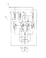
図2を参照すると、アクセスポイント100は、本体101の中に、HOSTI/F103、記憶領域104、送信フレーム制御部105、送信フレーム生成部106、無線送信部107、タイマー部108、受信フレーム制御部110、受信フレーム復号部111、及び無線受信部112を備えており、本体101の外側にアンテナ109を備えている。
Referring to FIG. 2, the
また、アクセスポイント100は、外部のホスト(HOST)102と接続されている。HOST102は、アクセスポイント100に対して、送信すべきデータや送信したい無線LAN端末のMAC(Media Access Control)アドレスを通知し、データの送信指示を出すことで制御を行う機能を有する。具体的には、PC(Personal Computer)や、家庭用電化製品などでは組み込みマイコン等で実現される。
The
HOSTI/F103は、HOST102と通信を行うインターフェイスであり、PCI(Peripheral Component Interconnect)等のバス規格によって実現されるが、特定のバスには限らない。HOSTI/F103は、HOST102から受け取った送信対象データを送信フレーム制御部105に送出し、また、受け取ったSTA1及びSTA2のMACアドレスを記憶領域104に書き込む機能を有する。
The HOST I /
記憶領域104は、無線LAN通信に必要な種々の情報を記憶するメモリであり、特に、HOSTI/F103から受け取った送信対象データ及びMACアドレスや、後述する受信フレーム制御部110から受け取ったデータを記憶する機能を有する。
送信フレーム制御部105は、データを送信する際、送信すべきデータと送信相手のMACアドレスを記憶領域104から取り出し、送信フレーム生成部106に送出する機能を有する。
The
The transmission
また、送信フレーム制御部105は、後述するタイマー部108からビーコン信号を送信すべき所定周期TBTTの計時を受けると、ビーコン信号のデータを生成して送信フレーム生成部106に送信する機能と、タイマー部108からビーコン信号に先行してエラーフレームを送信すべき時間Tの計時を受けると、エラーフレームのデータを生成して送信フレーム生成部106に送信する機能とを有する。エラーフレームは、通信端末10、20が受信したときにIEEE802.11規格上エラーとなる所定のデータから成るフレームである。
In addition, the transmission
送信フレーム生成部106は、IEEE802.11規格に則り、送信フレーム制御部105から受け取ったデータをフレーム形式に変換し、変換したフレームにMACアドレスを付加して送信フレームを生成して、無線送信部107に送出する機能を有する。
無線送信部107は、送信フレーム生成部106から受け取った送信フレームを、アンテナ109を介して送信する機能を有する。
The transmission
The
無線受信部112は、アンテナ109を介してフレームを受信し、受信フレーム復号部111に送出する機能を有する。
受信フレーム復号部111は、無線受信部112から受け取ったフレームをIEEE802.11規格に則って復号し、受信フレーム制御部110に送出する機能を有する。
受信フレーム制御部110は、受信フレーム復号部111から受け取った受信データを記憶領域104に書き込む機能を有する。また、受信制御部110は、受信したフレームの種類に応じて、フレームを受信してから一定時間送信を禁止しなければならないというIEEE802.11規格で規定されている所定時間tを送信フレーム制御部105に送出する機能を有する。
The
The reception
The reception
タイマー部108は、IEEE802.11規格に則り、ビーコン信号を周期的に送信するための所定周期TBTTと、ビーコン信号に先行してエラーフレームを送信するための所定周期Tとを計時する機能を有する。具体的には、Tは、TBTT−(IFS+バックオフ)<T<TBTTを満たす所定の時間Tである。
(3.動作)
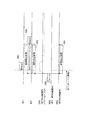
次に、アクセスポイント100の動作について、図3を参照しながら説明する。
The
(3. Operation)
Next, the operation of the
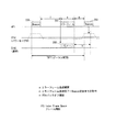
図3を参照すると、無線LANネットワーク内で、通信端末10がパワーセーブモードに設定されているものとする。
まず、アクセスポイント100において、タイマー部108がTBTTを計時すると、送信フレーム制御部105がビーコン信号のデータを生成し、送信フレーム生成部106がビーコン信号のフレームに変換して、無線送信部107がアンテナ109を介してビーコン信号200を送信する。
Referring to FIG. 3, it is assumed that the
First, in the
通信端末10は、前回以前に受信したビーコン信号内のTBTTに基づき、受信部を立ち上げてビーコン信号200を受信する。
同じく通信端末20も、ビーコン信号200を受信する。
アクセスポイント100は、ビーコン信号200を送信し終わった後、タイマー部108が所定時間Tを計時すると、送信フレーム制御部105がエラーフレーム201を生成し、送信フレーム生成部106と無線通信部107とアンテナ109とを介してエラーフレーム201を送信する。
The
Similarly, the
In the
これにより、通信端末20は、エラーフレーム201を受信すると、IEEE802.11規格に従い、エラーフレーム201を受信している間のビジー状態202(期間e)を経て、IFS+バックオフの期間(期間n)データの送信を禁止する。
そして、アクセスポイント100は、エラーフレーム201を送信後、期間mが経過した次のタイミングで、ビーコン信号203を送信する。
Thus, when the
Then, after transmitting the
ここで、ビーコン信号200の送信後にエラーフレーム201を送信するまでの時間Tが、TBTT−(IFS+バックオフ)<T<TBTTを満たすため、アクセスポイント100は、ビーコン信号200の送信後次のビーコン信号203を送信するまでの間にエラーフレーム201を送信し、且つ、エラーフレーム201の送信後に通信端末20がIFS+バックオフ(期間n)の間データ送信を禁止している間にビーコン信号203を送信することができる。
Here, since the time T until the
これによって、アクセスポイント100がビーコン信号を送信できる確実性が高まり、通信端末10がパワーセーブモードを継続できる確実性も高まる。
<実施形態2>
次に、本発明の実施形態2について、図面を参照しながら説明する。
(1.概要)
実施形態1では、アクセスポイント100は、ビーコン信号に先行してエラーフレームを送信するようになっていたが、実施形態2では、IEEE802.11規格で規定されているCTSフレームを送信する点で異なっている。
(2.AP1の構成)
構成については、実施形態1と異なる点についてのみ説明する。
This increases the certainty that the
<Embodiment 2>
Next, Embodiment 2 of the present invention will be described with reference to the drawings.
(1. Overview)
In the first embodiment, the
(2. Configuration of AP1)
Only the differences from the first embodiment will be described.
送信フレーム制御部105は、タイマー部108からビーコン信号に先行してCTSフレームを送信すべき時間Tの計時を受けると、CTSフレーム内に含むNAVを決定し、決定したNAVを含むCTSフレームのデータを生成して送信フレーム生成部106に送信する機能を有する。
タイマー部108は、IEEE802.11規格に則り、ビーコン信号を周期的に送信するための所定周期TBTTと、ビーコン信号に先行してCTSフレームを送信するための所定周期Tとを計時する機能を有する。具体的には、Tは、TBTT−NAV<T<TBTTを満たす所定の時間Tである。
(3.動作)
次に、アクセスポイント100の動作について、図4を参照しながら説明する。
When receiving a time T for transmitting the CTS frame prior to the beacon signal from the
The
(3. Operation)
Next, the operation of the
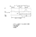
図4を参照すると、無線LANネットワーク内で、通信端末10がパワーセーブモードに設定されているものとする。
まず、アクセスポイント100において、タイマー部108がTBTTを計時すると、送信フレーム制御部105がビーコン信号のデータを生成し、送信フレーム生成部106がビーコン信号のフレームに変換して、無線送信部107がアンテナ109を介してビーコン信号300を送信する。
Referring to FIG. 4, it is assumed that the
First, in the
通信端末10は、前回以前に受信したビーコン信号内のTBTTに基づき、受信部を立ち上げてビーコン信号300を受信する。
同じく通信端末20も、ビーコン信号300を受信する。
アクセスポイント100は、ビーコン信号300を送信し終わった後、タイマー部108が所定時間Tを計時すると、送信フレーム制御部105がCTSフレーム301を生成し、送信フレーム生成部106と無線通信部107とアンテナ109とを介してCTSフレーム301を送信する。
The
Similarly, the
When the
これにより、通信端末20は、CTSフレーム301を受信すると、IEEE802.11規格に従い、CTSフレーム301を受信している間のビジー状態302(期間c)を経て、NAV期間(期間d)データの送信を禁止する。
そして、アクセスポイント100は、CTSフレーム301を送信後、期間aが経過した次のタイミングで、ビーコン信号303を送信する。
As a result, when the
Then, after transmitting the
ここで、ビーコン信号300の送信後にCTSフレーム301を送信するまでの時間Tが、TBTT−NAV<T<TBTTを満たすため、アクセスポイント100は、ビーコン信号300の送信後次のビーコン信号303を送信するまでの間にCTSフレーム301を送信し、且つ、CTSフレーム301の送信後に通信端末20がNAV期間(期間d)の間データ送信を禁止している間にビーコン信号303を送信することができる。
Here, since the time T until transmission of the
これによって、アクセスポイント100がビーコン信号を送信できる確実性が高まり、通信端末10がパワーセーブモードを継続できる確実性も高まる。
さらに、アクセスポイント100は、NAVを調整することで、通信端末20にデータの送信を禁止させる期間を調整することができる。
<実施形態3>
次に、本発明の実施形態3について、図面を参照しながら説明する。
(1.概要)
実施形態1では、アクセスポイント100は、ビーコン信号に先行してエラーフレームを送信するようになっていたが、実施形態3では、IEEE802.11規格で規定されているPLCPヘッダを送信する点で異なっている。
This increases the certainty that the
Furthermore, the
<Embodiment 3>
Next, Embodiment 3 of the present invention will be described with reference to the drawings.
(1. Overview)
In the first embodiment, the
図5(a)に示すように、IEEE802.11規格によれば、物理層で、送信データ402に、受信同期処理に必要なPLCPプリアンブル400とともに伝送レートやフレーム長等の情報が書き込まれているPLCPヘッダ401とが付加されるようになっている。
(2.AP1の構成)
構成については、実施形態1と異なる点についてのみ説明する。
As shown in FIG. 5A, according to the IEEE 802.11 standard, information such as a transmission rate and a frame length is written in
(2. Configuration of AP1)
Only the differences from the first embodiment will be described.
送信フレーム制御部105は、タイマー部108からビーコン信号に先行してPLCPヘッダを送信すべき時間Tの計時を受けると、PLCPヘッダ内に含むLengthを決定し、決定したLengthを含むPLCPヘッダを生成して送信フレーム生成部106に送信する機能を有する。
タイマー部108は、IEEE802.11規格に則り、ビーコン信号を周期的に送信するための所定周期TBTTと、ビーコン信号に先行してPLCPヘッダを送信するための所定周期Tとを計時する機能を有する。具体的には、Tは、TBTT−Length<T<TBTTを満たす所定の時間Tである。
(3.動作)
次に、アクセスポイント100の動作について、図5を参照しながら説明する。
When receiving a time T for transmitting the PLCP header prior to the beacon signal from the
The
(3. Operation)
Next, the operation of the
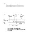
図5を参照すると、無線LANネットワーク内で、通信端末10がパワーセーブモードに設定されているものとする。
まず、アクセスポイント100において、タイマー部108がTBTTを計時すると、送信フレーム制御部105がビーコン信号のデータを生成し、送信フレーム生成部106がビーコン信号のフレームに変換して、無線送信部107がアンテナ109を介してビーコン信号403を送信する。
Referring to FIG. 5, it is assumed that the
First, in the
通信端末10は、前回以前に受信したビーコン信号内のTBTTに基づき、受信部を立ち上げてビーコン信号403を受信する。
同じく通信端末20も、ビーコン信号403を受信する。
アクセスポイント100は、ビーコン信号403を送信し終わった後、タイマー部108が所定時間Tを計時すると、送信フレーム制御部105がPLCPヘッダ404を生成し、送信フレーム生成部106と無線通信部107とアンテナ109とを介してPLCPヘッダ404を送信する。
The
Similarly, the
When the
これにより、通信端末20は、PLCPヘッダ404を受信すると、IEEE802.11規格に従い、PLCPヘッダ404を受信している間のビジー状態405(期間h)を経て、Length期間(期間l)データの送信を禁止する。
そして、アクセスポイント100は、PLCPヘッダ404を送信後、期間iが経過した次のタイミングで、ビーコン信号406を送信する。
As a result, when the
Then, after transmitting the
ここで、ビーコン信号403の送信後にPLCPヘッダ404を送信するまでの時間Tが、TBTT−Length<T<TBTTを満たすため、アクセスポイント100は、ビーコン信号403の送信後次のビーコン信号406を送信するまでの間にPLCPヘッダ404を送信し、且つ、PLCPヘッダ404の送信後に通信端末20がLength期間(期間l)の間データ送信を禁止している間にビーコン信号406を送信することができる。
Here, since the time T until the
これによって、アクセスポイント100がビーコン信号を送信できる確実性が高まり、通信端末10がパワーセーブモードを継続できる確実性も高まる。
さらに、アクセスポイント100は、Length期間を調整することで、通信端末20にデータの送信を禁止させる期間を調整することができる。
さらに、PLCPヘッダを送信する際に、データは無くてPLCPヘッダとPLCPプリアンブルのみで構わないので、容量が少なくネットワークへの負担を抑えることができる。
<実施形態4>
次に、本発明の実施形態4について、図面を参照しながら説明する。
(1.概要)
実施形態4では、さらにもう1台通信端末30(STA3)が無線LAN通信システムのネットワークに加わった。
This increases the certainty that the
Furthermore, the
Furthermore, when transmitting the PLCP header, there is no data and only the PLCP header and the PLCP preamble may be used, so the capacity is small and the burden on the network can be suppressed.
<Embodiment 4>
Next, Embodiment 4 of the present invention will be described with reference to the drawings.
(1. Overview)
In the fourth embodiment, another communication terminal 30 (STA3) is added to the network of the wireless LAN communication system.
実施形態1〜3では、アクセスポイント100は、ビーコン信号に先行してエラーフレーム、CTSフレーム、又はPLCPヘッダを送信するようになっていたが、実施形態4では、ビーコン信号に先行して通信端末30がエラーフレームを送信する点で異なっている。
(2−1.STA3の構成)
図6を参照しながら、通信端末30の構成について説明する。
In the first to third embodiments, the
(2-1. Configuration of STA3)
The configuration of the
図6を参照すると、通信端末30は、記憶領域31、送信フレーム制御部32、送信フレーム生成部33、無線送信部34、タイマー部35、アンテナ36、受信フレーム制御部37、受信フレーム復号部38、及び無線受信部39を備えている。
記憶領域31は、無線LAN通信に必要な種々の情報を記憶するメモリであり、特に、アクセスポイント100から受信したSSIDや他の通信端末10、20のMACアドレスや、アクセスポイント100がビーコン信号を送信する周期であるTBTTを記憶する機能を有する。
Referring to FIG. 6, the
The
送信フレーム制御部32は、データを送信する際、送信すべきデータと送信相手のMACアドレスを記憶領域31から取り出し、送信フレーム生成部33に送出する機能を有する。
また、送信フレーム制御部32は、後述するタイマー部35からエラーフレームを送信すべき時間Tの計時を受けると、エラーフレームのデータを生成して送信フレーム生成部33に送信する機能を有する。エラーフレームは、通信端末10、20が受信したときにIEEE802.11規格上エラーとなる所定のデータから成るフレームである。
The transmission
The transmission
送信フレーム生成部33は、IEEE802.11規格に則り、送信フレーム制御部32から受け取ったデータをフレーム形式に変換し、変換したフレームにMACアドレスを付加して送信フレームを生成して、無線送信部34に送出する機能を有する。
無線送信部34は、送信フレーム生成部33から受け取った送信フレームを、アンテナ36を介して送信する機能を有する。
The transmission
The
無線受信部39は、アンテナ36を介してフレームを受信し、受信フレーム復号部35に送出する機能を有する。
受信フレーム復号部38は、無線受信部39から受け取ったフレームをIEEE802.11規格に則って復号し、受信フレーム制御部37に送出する機能を有する。
受信フレーム制御部37は、受信フレーム復号部38から受け取った受信データを記憶領域31に書き込む機能を有する。また、受信制御部110は、受信したフレームの種類に応じて、フレームを受信してから一定時間送信を禁止しなければならないというIEEE802.11規格で規定されている所定時間tを送信フレーム制御部32に送出する機能を有する。
The
The reception
The reception
タイマー部35は、記憶領域31に記憶されているTBTTに基づき、アクセスポイント100のビーコン信号送信に先行してエラーフレームを送信するための所定周期Tを計時する機能を有する。具体的には、Tは、TBTT−(IFS+バックオフ)<T<TBTTを満たす所定の時間Tである。
(2−2.AP1の構成)
AP1の構成については、実施形態1と異なる点について説明する。
The
(2-2. Configuration of AP1)
Regarding the configuration of the
送信フレーム制御部105は、するタイマー部108からビーコン信号を送信すべき所定周期TBTTの計時を受けると、ビーコン信号のデータを生成して送信フレーム生成部106に送信する機能を有する。
特に、データの送信を禁止しなければならない所定時間t内に、タイマー部108からビーコン信号を送信すべき所定周期TBTTの計時を受けたときは、データ送信禁止を無視して強制的にビーコン信号を生成する機能を有する。
The transmission
In particular, when a time period of a predetermined period TBTT in which a beacon signal is to be transmitted is received from the
タイマー部108は、IEEE802.11規格に則り、ビーコン信号を周期的に送信するための所定周期TBTTを計時する機能を有する。
(3.動作)
次に、通信端末30及びアクセスポイント100の動作について、図7を参照しながら説明する。
The
(3. Operation)
Next, operations of the
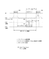
図7を参照すると、無線LANネットワーク内で、通信端末10がパワーセーブモードに設定されているものとする。
まず、アクセスポイント100において、タイマー部108がTBTTを計時すると、送信フレーム制御部105がビーコン信号のデータを生成し、送信フレーム生成部106がビーコン信号のフレームに変換して、無線送信部107がアンテナ109を介してビーコン信号600を送信する。
Referring to FIG. 7, it is assumed that the
First, in the
通信端末10は、前回以前に受信したビーコン信号内のTBTTに基づき、受信部を立ち上げてビーコン信号600を受信する。
同じく通信端末20及び30も、ビーコン信号600を受信する。
通信端末30は、ビーコン信号600を受信した後、タイマー部35が所定時間Tを計時すると、送信フレーム制御部32がエラーフレーム501を生成し、送信フレーム生成部33と無線通信部34とアンテナ36とを介してエラーフレーム501を送信する。
The
Similarly, the
After receiving the
これにより、通信端末20は、エラーフレーム501を受信すると、IEEE802.11規格に従い、エラーフレーム501を受信している間のビジー状態502(期間h)を経て、IFS+バックオフ期間(期間n)データの送信を禁止する。
そして、アクセスポイント100は、エラーフレーム501を受信後、通信端末20と同様にIFS+バックオフ期間データの送信を禁止しているが、期間mが経過してタイマー108がTBTTを計時すると、データ送信の禁止を無視して強制的にビーコン信号503を送信する。
Thus, when the
Then, after receiving the
ここで、ビーコン信号500の受信後にエラーフレーム501を送信するまでの時間Tが、TBTT−(IFS+バックオフ)<T<TBTTを満たすため、通信端末30は、ビーコン信号500の受信後次のビーコン信号503を受信するまでの間にエラーフレーム501を送信し、且つ、エラーフレーム501の送信後に通信端末20がIFS+バックオフ期間(期間n)の間データ送信を禁止している間にアクセスポイント100はビーコン信号503を送信することができる。
Here, since the time T until the transmission of the
これによって、アクセスポイント100がビーコン信号を送信できる確実性が高まり、通信端末10がパワーセーブモードを継続できる確実性も高まる。
また、ビーコン信号に先行するエラーフレームの送信を通信端末30が行うため、アクセスポイント100は処理の負担を軽減することができる。
<実施形態5>
次に、本発明の実施形態5について、図面を参照しながら説明する。
(1.概要)
実施形態4では、通信端末30は、ビーコン信号に先行してエラーフレームを送信するようになっていたが、実施形態5では、IEEE802.11規格で規定されているCTSフレームを送信する点で異なっている。
(2.STA3の構成)
構成については、実施形態4と異なる点についてのみ説明する。
This increases the certainty that the
Moreover, since the
<Embodiment 5>
Next, Embodiment 5 of the present invention will be described with reference to the drawings.
(1. Overview)
In the fourth embodiment, the
(2. Configuration of STA3)
As for the configuration, only differences from the fourth embodiment will be described.
送信フレーム制御部32は、タイマー部35からCTSフレームを送信すべき時間Tの計時を受けると、CTSフレーム内に含むNAVを決定し、決定したNAVを含むCTSフレームのデータを生成して送信フレーム生成部33に送信する機能を有する。
タイマー部35は、記憶領域31に記憶されているTBTTに基づき、アクセスポイント100のビーコン信号送信に先行してCTSフレームを送信するための所定周期Tを計時する機能を有する。具体的には、Tは、TBTT−NAV<T<TBTTを満たす所定の時間Tである。
(3.動作)
次に、通信端末30及びアクセスポイント100の動作について、図8を参照しながら説明する。
When receiving the time T for transmitting the CTS frame from the
The
(3. Operation)
Next, operations of the
図8を参照すると、無線LANネットワーク内で、通信端末10がパワーセーブモードに設定されているものとする。
まず、アクセスポイント100において、タイマー部108がTBTTを計時すると、送信フレーム制御部105がビーコン信号のデータを生成し、送信フレーム生成部106がビーコン信号のフレームに変換して、無線送信部107がアンテナ109を介してビーコン信号600を送信する。
Referring to FIG. 8, it is assumed that the
First, in the
通信端末10は、前回以前に受信したビーコン信号内のTBTTに基づき、受信部を立ち上げてビーコン信号600を受信する。
同じく通信端末20及び30も、ビーコン信号600を受信する。
通信端末30は、ビーコン信号600を受信した後、タイマー部35が所定時間Tを計時すると、送信フレーム制御部32がCTSフレーム601を生成し、送信フレーム生成部33と無線通信部34とアンテナ36とを介してCTSフレーム601を送信する。
The
Similarly, the
In the
これにより、通信端末20は、CTSフレーム601を受信すると、IEEE802.11規格に従い、CTSフレーム601を受信している間のビジー状態602(期間c)を経て、NAV期間(期間d)データの送信を禁止する。
そして、アクセスポイント100は、CTSフレーム601を受信後、通信端末20と同様にNAV期間データの送信を禁止しているが、期間aが経過してタイマー108がTBTTを計時すると、データ送信の禁止を無視して強制的にビーコン信号603を送信する。
As a result, when the
Then, after receiving the
ここで、ビーコン信号600の受信後にCTSフレーム601を送信するまでの時間Tが、TBTT−NAV<T<TBTTを満たすため、通信端末30は、ビーコン信号600の受信後次のビーコン信号603を受信するまでの間にCTSフレーム601を送信し、且つ、CTSフレーム601の送信後に通信端末20がNAV期間(期間d)の間データ送信を禁止している間にアクセスポイント100はビーコン信号603を送信することができる。
Here, since the time T until the
これによって、アクセスポイント100がビーコン信号を送信できる確実性が高まり、通信端末10がパワーセーブモードを継続できる確実性も高まる。
また、ビーコン信号に先行するエラーフレームの送信を通信端末30が行うため、アクセスポイント100は処理の負担を軽減することができる。
さらに、通信端末30は、NAVを調整することで、通信端末20にデータの送信を禁止させる期間を調整することができる。
<実施形態6>
次に、本発明の実施形態6について、図面を参照しながら説明する。
(1.概要)
実施形態4では、通信端末30は、ビーコン信号に先行してエラーフレームを送信するようになっていたが、実施形態5では、IEEE802.11規格で規定されているPLCPヘッダを送信する点で異なっている。
(2.STA3の構成)
構成については、実施形態4と異なる点についてのみ説明する。
This increases the certainty that the
Moreover, since the
Furthermore, the
<Embodiment 6>
Next, Embodiment 6 of the present invention will be described with reference to the drawings.
(1. Overview)
In the fourth embodiment, the
(2. Configuration of STA3)
As for the configuration, only differences from the fourth embodiment will be described.
送信フレーム制御部32は、タイマー部35からPLCPヘッダを送信すべき時間Tの計時を受けると、PLCPヘッダ内に含むLengthを決定し、決定したLengthを含むPLCPヘッダのデータを生成して送信フレーム生成部33に送信する機能を有する。
タイマー部35は、記憶領域31に記憶されているTBTTに基づき、アクセスポイント100のビーコン信号送信に先行してPLCPヘッダを送信するための所定周期Tを計時する機能を有する。具体的には、Tは、TBTT−Length<T<TBTTを満たす所定の時間Tである。
(3.動作)
次に、通信端末30及びアクセスポイント100の動作について、図9を参照しながら説明する。
When receiving the time T for transmitting the PLCP header from the
The
(3. Operation)
Next, operations of the
図9を参照すると、無線LANネットワーク内で、通信端末10がパワーセーブモードに設定されているものとする。
まず、アクセスポイント100において、タイマー部108がTBTTを計時すると、送信フレーム制御部105がビーコン信号のデータを生成し、送信フレーム生成部106がビーコン信号のフレームに変換して、無線送信部107がアンテナ109を介してビーコン信号700を送信する。
Referring to FIG. 9, it is assumed that the
First, in the
通信端末10は、前回以前に受信したビーコン信号内のTBTTに基づき、受信部を立ち上げてビーコン信号700を受信する。
同じく通信端末20及び30も、ビーコン信号700を受信する。
通信端末30は、ビーコン信号700を受信した後、タイマー部35が所定時間Tを計時すると、送信フレーム制御部32がPLCPヘッダ701を生成し、送信フレーム生成部33と無線通信部34とアンテナ36とを介してPLCPヘッダ701を送信する。
The
Similarly, the
In the
これにより、通信端末20は、PLCPヘッダ701を受信すると、IEEE802.11規格に従い、PLCPヘッダ701を受信している間のビジー状態702(期間h)を経て、Length期間(期間l)データの送信を禁止する。
そして、アクセスポイント100は、PLCPヘッダ701を受信後、通信端末20と同様にLength期間データの送信を禁止しているが、期間iが経過してタイマー108がTBTTを計時すると、データ送信の禁止を無視して強制的にビーコン信号703を送信する。
Thus, when the
Then, after receiving the PLCP header 701, the
ここで、ビーコン信号700の受信後にPLCPヘッダ701を送信するまでの時間Tが、TBTT−Length<T<TBTTを満たすため、通信端末30は、ビーコン信号700の受信後次のビーコン信号703を受信するまでの間にPLCPヘッダ701を送信し、且つ、PLCPヘッダ701の送信後に通信端末20がLength期間(期間l)の間データ送信を禁止している間にアクセスポイント100はビーコン信号703を送信することができる。
Here, since the time T until the PLCP header 701 is transmitted after receiving the
これによって、アクセスポイント100がビーコン信号を送信できる確実性が高まり、通信端末10がパワーセーブモードを継続できる確実性も高まる。
また、ビーコン信号に先行するエラーフレームの送信を通信端末30が行うため、アクセスポイント100は処理の負担を軽減することができる。
さらに、通信端末30は、Lengthを調整することで、通信端末20にデータの送信を禁止させる期間を調整することができる。
This increases the certainty that the
Moreover, since the
Furthermore, the
さらに、PLCPヘッダを送信する際に、データは無くてPLCPヘッダとPLCPプリアンブルのみで構わないので、容量が少なくネットワークへの負担を抑えることができる。
<実施形態7>
次に、本発明の実施形態7について、図面を参照しながら説明する。
(1.概要)
実施形態7では、さらにもう2台通信端末40、50(STA4、STA5)が無線LAN通信システムのネットワークに加わった。
Furthermore, when transmitting the PLCP header, there is no data and only the PLCP header and the PLCP preamble may be used, so the capacity is small and the burden on the network can be suppressed.
<Embodiment 7>
Next, a seventh embodiment of the present invention will be described with reference to the drawings.
(1. Overview)
In the seventh embodiment, two
実施形態1〜3では、アクセスポイント100は、ビーコン信号に先行してエラーフレーム、CTSフレーム、又はPLCPヘッダを送信するようになっていた。また、実施形態4〜6では、通信端末30が、アクセスポイント100が送信するビーコン信号に先行して、エラーフレーム、CTSフレーム、又はPLCPヘッダを送信するようになっていた。
In the first to third embodiments, the
これに対して、実施形態7では、アクセスポイント100と通信端末のいずれかとが協力し、両者がそれぞれRTSフレームとCTSフレームを送信する点で異なっている。
実施形態7に係る無線LAN通信システムについて、図10を参照しながら説明する。
図10に示すように、実施形態10の無線LAN通信システム内に、通信端末10〜50(STA1〜STA5)が存在している。通信端末10〜30は、アクセスポイント100からキャリアセンス可能な範囲に存在しているが、通信端末40については、電波を遮蔽する遮蔽物60が介在することによってアクセスポイント100がキャリアセンス不可能な状態に陥っている。また、通信端末50については、アクセスポイント100がキャリアセンス可能な電波到達範囲に外れて移動していることから、キャリアセンスが不可能な状態に陥っている。
(2−1.AP1の構成)
図11を参照しながら、アクセスポイント100の構成について説明する。
On the other hand, the seventh embodiment is different in that either the
A wireless LAN communication system according to the seventh embodiment will be described with reference to FIG.
As shown in FIG. 10,
(2-1. Configuration of AP1)
The configuration of the
構成については、実施形態1と異なる点について説明する。
図11を参照すると、アクセスポイント100は、本体101内に新たにバッテリ残量調査部113を備える。
バッテリ残量調査部113は、無線LAN通信システム内の通信端末10〜50それぞれのバッテリ残量を調査するために、バッテリ残量を問合せるフレームを生成するよう送信フレーム制御部105に依頼する機能を有する。
About a structure, a different point from
Referring to FIG. 11, the
The battery remaining
送信フレーム制御部105は、バッテリ残量調査部113からの依頼を受け、通信端末10〜50に対して送信するバッテリ残量通知要求フレームのデータを生成して送信フレーム106に送出する機能を有する。
また、送信フレーム制御部105は、タイマー部108より所定時間Tの計時を受けると、RTSフレームのデータを生成して送信フレーム生成部105に送出する機能を有する。
The transmission
Further, the transmission
送信フレーム生成部106は、送信フレーム制御部105から受け取ったデータに基づき、バッテリ残量通知要求フレームを生成して、無線送信部107に送出する機能を有する。
タイマー部108は、IEEE802.11規格に則り、ビーコン信号を周期的に送信するための所定周期TBTTと、ビーコン信号に先行してRTSフレームを送信するための所定周期Tとを計時する機能を有する。具体的には、Tは、TBTT−NAV<T<TBTTを満たす所定の時間Tである。
(2−2.STA1〜5の構成)
通信端末10〜50の構成について、ここでは便宜的に通信端末30を例に挙げて、実施形態4と異なる点について説明する。また、各通信端末10〜50は同様の構成を有するものとする。
The transmission
The
(2-2. Configuration of STA1-5)
The configuration of the
記憶領域31は、送信フレーム制御部32がバッテリ残量通知フレームを送信するのに必要なバッテリ残量の閾値Rを記憶している。
送信フレーム制御部32は、受信フレーム制御部37からRTSフレーム受信の通知を受けると、CTSフレーム内に含むNAVを決定し、決定したNAVを含むCTSフレームのデータを生成して送信フレーム生成部33に送信する機能を有する。
The
When receiving the RTS frame reception notification from the reception
また、送信フレーム制御部32は、受信フレーム制御部37からバッテリ残量通知要求フレーム受信の通知を受けると、自端末30のバッテリ残量を通知するためのバッテリ残量通知フレームのデータを生成して送信フレーム生成部33に送信する機能を有する。
受信フレーム制御部37は、受信フレーム復号部38から受け取った受信データがRTSフレームであった場合、その旨を送信フレーム制御部32に通知する機能を有する。
Further, when the transmission
The reception
また、受信フレーム制御部37は、受信フレーム復号部38から受け取った受信データがバッテリ通知要求フレームであった場合には、その旨を送信フレーム制御部32に通知する機能を有する。
(3.データ)
ここで、バッテリ残量通知要求フレームのデータ構成と、バッテリ残量通知フレームのデータ構成について、図12を参照しながら説明する。
The reception
(3. Data)
Here, the data structure of the battery remaining amount notification request frame and the data structure of the battery remaining amount notification frame will be described with reference to FIG.
図12(a)を参照すると、バッテリ残量通知要求フレームは、フレーム制御フィールド900、Duration/IDフィールド901、受信局アドレスフィールド902、送信局アドレスフィールド903、及びFCSフィールド904を含んで成る。
フレーム制御フィールド900は2byteであり、この中に、プロトコルバージョンフィールドに続いてタイプフィールド905、サブタイプフィールド906等のフィールドがある。例えば、IEEE802.11規格に則り、タイプフィールド905が「10」のときは、データタイプを示している。また、サブタイプフィールド906において「0000」〜「1001」は予約フィールドであり、ここでは「0110」を利用している。
Referring to FIG. 12A, the battery remaining amount notification request frame includes a
The
アクセスポイント100は、受信局アドレス901に通信端末10〜50のMACアドレスを設定することで、各通信端末に送信する。
図12(b)を参照すると、バッテリ残量通知フレームも同様に、フレーム制御フィールド907、Duration/IDフィールド908、受信局アドレスフィールド909、バッテリ残量フィールド910、及びFCSフィールド911を含んで成る。
The
Referring to FIG. 12B, the battery remaining amount notification frame similarly includes a
通信端末30は、受信局アドレス908にアクセスポイント100のMACアドレスを設定することで、アクセスポイント100に送信する。
(3.動作)
次に、通信端末30及びアクセスポイント100の動作について、図13〜15を参照しながら説明する。なお、ここでは、通信端末20は省略し、通信端末10、30、40、及び50に着目して図示する。
(3−1.動作 その1)
まず、アクセスポイント100が各通信端末10〜50のバッテリ残量を調査する処理動作について、図13を参照しながら説明する。
The
(3. Operation)
Next, operations of the
(3-1. Operation 1)
First, the processing operation in which the
図13を参照すると、まず、アクセスポイント100は、無線LANネットワーク内の通信端末数(5)を取得する(ステップS100)。
送信フレーム制御部105は、変数iを「1」に初期化して(ステップS101)、まず通信端末10(STA1)に対してバッテリ残量通知要求フレームを送信するよう、送信フレーム生成部106に指示する(ステップS102)。
Referring to FIG. 13, first, the
The transmission
次に、アクセスポイント100は、通信端末10からバッテリ残量通知フレームを受信すると(ステップS103:はい)、記憶領域104に通信端末10のバッテリ残量を記憶する(ステップS104)。
続いて、変数iをインクリメントして(ステップS105)、通信端末50のバッテリ残量調査が完了するまで(ステップS106:はい)、各通信端末に対してバッテリ残量通知要求フレームを送信する。
Next, when the
Subsequently, the variable i is incremented (step S105), and a battery remaining amount notification request frame is transmitted to each communication terminal until the battery remaining amount investigation of the
全通信端末10〜50からバッテリ残量通知を受信すると(ステップS106:いいえ)、記憶領域104に記憶した各通信端末のバッテリ残量を比較し、最もバッテリ残量の大きい通信端末を抽出する(ステップS107)。
(3−2.動作 その2)
次に、通信端末30が自端末のバッテリ残量をアクセスポイント100に通知する処理動作について、図14を参照しながら説明する。
When the battery remaining amount notification is received from all the
(3-2. Operation 2)
Next, a processing operation in which the
図14を参照すると、まず、通信端末30は、自端末のバッテリ残量を取得し(ステップS200)、この残量が記憶領域104に記憶してある閾値Rよりも大きい場合には(ステップS201:はい)、送信フレーム生成部33に対してバッテリ残量通知フレームを送信するよう指示する(ステップS202)。
一方、取得した自端末のバッテリ残量が閾値Rよりも小さい場合は(ステップS201:いいえ)、送信フレーム生成部33に対してバッテリ残量通知フレームの送信は指示しない(ステップS203)。
(3−3.動作 その3)
次に、アクセスポイント100が各通信端末10〜50のバッテリ残量を取得した後、アクセスポイント100と最もバッテリ残量が大きい通信端末(ここでは、通信端末30とする)とが協力して両者がそれぞれRTSフレームとCTSフレームを送信する処理動作について、図15を参照しながら説明する。
Referring to FIG. 14, first, the
On the other hand, when the acquired battery remaining amount of the terminal is smaller than the threshold value R (step S201: No), the transmission
(3-3. Operation 3)
Next, after the
図15を参照すると、無線LANネットワーク内で、通信端末10がパワーセーブモードに設定されているものとする。
まず、アクセスポイント100において、タイマー部108がTBTTを計時すると、送信フレーム制御部105がビーコン信号のデータを生成し、送信フレーム生成部106がビーコン信号のフレームに変換して、無線送信部107がアンテナ109を介してビーコン信号800を送信する。
Referring to FIG. 15, it is assumed that the
First, in the
通信端末10は、前回以前に受信したビーコン信号内のTBTTに基づき、受信部を立ち上げてビーコン信号800を受信する。
同じく通信端末20〜40も、ビーコン信号800を受信する。
アクセスポイント100は、ビーコン信号800を受信した後、タイマー部108が所定時間Tを計時すると、送信フレーム制御部105が、最もバッテリ残量の大きい通信端末30宛てのRTSフレーム801を生成し、送信フレーム生成部106と無線通信部107とアンテナ109とを介してRTSフレーム801を通信端末30に送信する。
The
Similarly, the
When the
これにより、通信端末30は、RTSフレーム801を受信すると、IEEE802.11規格に従い、RTSフレーム801を受信している間のビジー状態(期間r)を経て、RTSフレームの応答信号であるCTSフレーム802を送信する。
CTSフレーム802を受信した通信端末40、50は、NAV期間(期間t)データの送信を禁止する。
一方、アクセスポイント100は、CTSフレーム802を受信後、通信端末40、50と同様にNAV期間データの送信を禁止しているが、期間sが経過してタイマー108がTBTTを計時すると、データ送信の禁止を無視して強制的にビーコン信号803を送信する。
Thus, when the
The
On the other hand, after receiving the
このように動作することで、アクセスポイント100がビーコン信号を送信できる確実性が高まり、通信端末10がパワーセーブモードを継続できる確実性も高まる。
特に、アクセスポイント100と通信端末30とが協力することで、アクセスポイント100からキャリアセンスが不可能な通信端末(通信端末40、50)に対してもデータ送信の禁止を行わせる確実性を高めることができる。
<実施形態8>
次に、本発明の実施形態8について、図面を参照しながら説明する。
(1.概要)
実施形態7では、最もバッテリ残量の多い通信端末とアクセスポイント100とが協力してRTSフレームとCTSフレームの送信を行っているが、実施形態8では、アクセスポイント100と最も通信品質の悪い通信端末が協力する点で異なっている。
(2−1.AP1の構成)
構成については、実施形態7と異なる点について説明する。
By operating in this way, the certainty that the
In particular, the cooperation between the
<Embodiment 8>
Next, an eighth embodiment of the present invention will be described with reference to the drawings.
(1. Overview)
In the seventh embodiment, the communication terminal with the largest remaining battery capacity and the
(2-1. Configuration of AP1)
About a structure, a different point from Embodiment 7 is demonstrated.
送信フレーム制御部105は、タイマー部108より所定時間Tの計時を受けると、RTSフレームのデータを生成して送信フレーム生成部105に送出する機能を有する。
送信フレーム生成部106は、送信フレーム制御部105からRTSフレームの送信要求を受けると、記憶領域104に記憶されている各通信端末10〜50のRSSI値を比較し、最もRSSI値の低い通信端末に対してRTSフレームを生成して無線送信部107に送出する機能を有する。
The transmission
Upon receiving an RTS frame transmission request from the transmission
受信フレーム制御部110は、各通信端末10〜50から何かしら信号を受信するたびに、RSSI値を記憶領域104に記憶する機能を有する。
(3.動作)
次に、アクセスポイント100が、各通信端末10〜50のいずれの通信端末にETSフレームを送信するかを決定する処理動作について、図16を参照しながら説明する。
The reception
(3. Operation)
Next, a processing operation in which the
まず、図16(a)に示すように、アクセスポイント100は、各通信端末10〜50から何がしかのフレームを受信するたびに(ステップS400:はい)、そのときのRSSI値を記憶領域104に記憶しておく(ステップS401)。
そして、図16(b)に示すように、ビーコン信号の受信後、タイマー部108が所定時間Tを計時すると、送信フレーム制御部105が、記憶領域104を参照して最もRSSI値の小さい通信端末を抽出する(ステップS402)。
First, as shown in FIG. 16A, the
Then, as shown in FIG. 16B, when the
この後は、図15に示す実施形態7の動作と同様であるため、詳述しない。
このようにアクセスポイント100が最もRSSI値の小さい通信端末にRTSフレームを送信することで、アクセスポイント100からより遠く、キャリアセンスが可能な領域ぎりぎりに存在する通信端末と協力する確実性を高めることができる。
これにより、遮蔽物で遮られてアクセスポイント100とキャリアセンスできない通信端末や、キャリアセンス可能な領域から外れてしまった通信端末に対して、他の通信端末がCTSフレームを送信する確実性を高めることができる。
<変形例>
以上、実施形態1〜8の構成について説明してきたが、これらの構成には種々の変形を加えることが可能である。
(1)例えば、実施形態8では、アクセスポイント100がRSSI値の最も小さい通信端末にRTSフレームを送信する例について説明したが、さらに、RSSI値に閾値を定め、この閾値よりも小さい場合にのみRTSフレームを送信するようにしてもよい。
The subsequent operation is the same as that of the seventh embodiment shown in FIG.
In this way, by transmitting the RTS frame to the communication terminal having the smallest RSSI value, the
This improves the certainty that another communication terminal transmits a CTS frame to a communication terminal that is blocked by an obstruction and cannot carrier sense with the
<Modification>
As mentioned above, although the structure of Embodiment 1-8 has been demonstrated, it is possible to add various deformation | transformation to these structures.
(1) For example, in the eighth embodiment, an example in which the
図17を参照すると、まず図17(a)に示すようにアクセスポイント100が各通信端末10〜50のRSSI値を記憶領域104に記憶しておき(ステップS500〜S501)、図17(b)に示すように、記憶領域14から読み出したRSSI値が予め定めておいた閾値より小さい場合には(ステップS503:はい)、RTSフレームの送信を指示し(ステップS504)し、RSSI値が閾値より大きい場合は(ステップS503:いいえ)、RTSフレームは送信しない(ステップS505)。
(2)また、例えば、実施形態8では、アクセスポイント100が通信端末10〜50から何かしらのフレームを受信するたびにRSSI値を記憶するようにしているが、アクセスポイント100が自発的にRSSI値を調査するためのフレームを送信するようにしてもよい。
Referring to FIG. 17, first, as shown in FIG. 17A, the
(2) For example, in the eighth embodiment, the RSSI value is stored every time the
図18を参照すると、まず、アクセスポイント100は、無線LANネットワーク内の通信端末数(5)を取得する(ステップS300)。
送信フレーム制御部105は、変数iを「1」に初期化して(ステップS301)、まず通信端末10(STA1)に対してNULLフレームを送信するよう、送信フレーム生成部106に指示する(ステップS302)。
Referring to FIG. 18, first, the
The transmission
次に、アクセスポイント100は、通信端末10からACK信号を受信すると(ステップS303:はい)、記憶領域104に通信端末10のRSSI値を記憶する(ステップS304)。
続いて、変数iをインクリメントして(ステップS305)、通信端末50のバッテリ残量調査が完了するまで(ステップS306:はい)、各通信端末に対してNULLフレームを送信する。
Next, when receiving an ACK signal from the communication terminal 10 (step S303: Yes), the
Subsequently, the variable i is incremented (step S305), and a NULL frame is transmitted to each communication terminal until the battery remaining amount investigation of the
全通信端末10〜50からACK信号を受信すると(ステップS306:いいえ)、記憶領域104に記憶した各通信端末のRSSI値を比較し、最もRSSI値の小さい通信端末を抽出する(ステップS307)。
<組み合わせ例>
さらに、以上説明したアクセスポイントや通信端末を組み合わせて無線LANネットワークを構築することも可能である。
When ACK signals are received from all the
<Example of combination>
Furthermore, a wireless LAN network can be constructed by combining the access points and communication terminals described above.
例えば、図19に示すように、アクセスポイント100a(AP1)及び通信端末10、20(STA1、STA2)を含んで成る無線LANネットワークを、アクセスポイント100b(AP2)及び通信端末20、30(STA2、STA3)を含んで成る無線LANネットワークと組み合わせる。
アクセスポイント100a及び通信端末20は、実施形態4に示した構成を有している。
For example, as shown in FIG. 19, a wireless LAN network including an
The
このときのアクセスポイント100a、100b及び通信端末10〜30の動作について、図20を参照しながら説明する。
図20を参照すると、いま、通信端末10がパワーセーブモードに設定されているものとする。
ここで、通信端末20がビーコン信号1003に先行してエラーフレーム1000を送信することで、アクセスポイント100b及び通信端末30がそれぞれIFS+バックオフ期間1001、1002データの送信を禁止する。アクセスポイント100aもIFS+バックオフ期間データの送信を禁止するが、ビーコン信号1003を送信するタイミングになると、送信禁止を無視して強制的にビーコン信号1003を送信する。
The operations of the
Referring to FIG. 20, it is assumed that the
Here, when the
アクセスポイント100bは、送信禁止期間を過ぎてからビーコン信号1004を送信することができる。
このようにアクセスポイント100aのみが送信禁止期間を無視してビーコン信号を送信することで、アクセスポイント100aと100bとの間でビーコン信号の衝突を防ぐことができ、アクセスポイント100aがビーコン信号を適切なタイミングで送信する確実性を高めることができる。
The
In this way, only the
これよって、通信端末10がビーコン信号1003の受信の受信に失敗してパワーセーブモードから復帰してしまうことを防ぐことができる。
このように、本発明のアクセスポイントと通信端末を使用することで、他の無線LAN通信システムより優先的に無線LANシステムを運用することができる。
Accordingly, it is possible to prevent the
Thus, by using the access point and communication terminal of the present invention, the wireless LAN system can be operated with priority over other wireless LAN communication systems.
本発明に係るアクセスポイント、通信端末、及び通信システムは、無線LANネットワークに広く適用可能であり、アクセスポイントがビーコン信号を送信する確実性を高めることができる点で有用な技術である。 The access point, communication terminal, and communication system according to the present invention are widely applicable to a wireless LAN network, and are useful techniques in that the access point can increase the certainty of transmitting a beacon signal.
10、20、30、40、50 通信端末
31 記憶領域
32 送信フレーム制御部
33 送信フレーム生成部
34 無線送信部
35 タイマー部
36 アンテナ
37 受信フレーム制御部
38 受信フレーム復号部
39 無線受信部
100 アクセスポイント
101 本体
102 ホスト(HOST)
103 HOSTI/F
104 記憶領域
105 送信フレーム制御部
106 送信フレーム生成部
107 無線送信部
108 タイマー部
109 アンテナ
110 受信フレーム制御部
111 受信フレーム復号部
112 無線受信部
10, 20, 30, 40, 50
103 HOSTI / F
Claims (13)
前記通信端末に対して、所定時間Tb間隔でビーコン信号の送信を行い、所定時間tの間、前記通信端末に信号の送信を禁止させるための所定の信号の送信を行う送信手段と、
ビーコン信号の送信後に、Tb−t<T<Tbを満たす所定時間Tが経過すると前記所定の信号を送信するよう前記送信手段を制御する制御手段とを備える
ことを特徴とする中継装置。 A relay device that relays communication between communication terminals according to access control according to the CSMA / CA method,
Transmitting means for transmitting a beacon signal to the communication terminal at a predetermined time interval Tb, and transmitting a predetermined signal for prohibiting the communication terminal from transmitting a signal for a predetermined time t;
And a control unit that controls the transmission unit to transmit the predetermined signal when a predetermined time T satisfying Tb-t <T <Tb elapses after the transmission of the beacon signal.
ことを特徴とする請求項1記載の中継装置。 The communication terminal has a power save mode for suppressing battery consumption in the terminal itself, and continues the power save mode by receiving the beacon signal at the predetermined time Tb interval. The relay device according to 1.
前記所定の信号は、エラーフレームであり、
前記所定時間tは、前記規格で規定されているIFSとバックオフとの合計時間である
ことを特徴とする請求項1記載の中継装置。 The communication terminal and the relay device comply with the IEEE 802.11 standard,
The predetermined signal is an error frame;
The relay apparatus according to claim 1, wherein the predetermined time t is a total time of IFS and backoff defined in the standard.
前記所定の信号は、前記規格で規定されているCTSフレームであり、
前記所定時間tは、前記CTSフレーム内に含まれるNAVが示す期間である
ことを特徴とする請求項1記載の中継装置。 The communication terminal and the relay device comply with the IEEE 802.11 standard,
The predetermined signal is a CTS frame defined in the standard,
The relay apparatus according to claim 1, wherein the predetermined time t is a period indicated by a NAV included in the CTS frame.
前記所定の信号は、前記規格で規定されているPLCPヘッダであり、
前記所定時間tは、前記PLCPヘッダ内に含まれるLengthが示す期間である
ことを特徴とする請求項1記載の中継装置。 The communication terminal and the relay device comply with the IEEE 802.11 standard,
The predetermined signal is a PLCP header defined in the standard,
The relay apparatus according to claim 1, wherein the predetermined time t is a period indicated by Length included in the PLCP header.
前記通信端末に信号を送信する送信手段と、
前記送信手段でビーコン信号を送信する場合に限り、前記所定時間tに関わらず送信するよう前記送信手段を制御する制御手段とを備える
ことを特徴とする中継装置。 A relay device that mediates communication between a plurality of communication terminals that are prohibited from transmitting a signal for a predetermined time t after receiving a signal according to access control according to the CSMA / CA method,
Transmitting means for transmitting a signal to the communication terminal;
And a control unit that controls the transmission unit to transmit the beacon signal regardless of the predetermined time t only when the transmission unit transmits a beacon signal.
前記中継装置は、
CTSフレームを受信する受信手段と、
前記通信端末に対して、所定時間Tb間隔でビーコン信号の送信を行い、RTSフレームの送信を行う送信手段と、
ビーコン信号の送信後に、Tb−t<T<Tbを満たす所定時間Tが経過すると前記RTSフレームを送信するよう前記送信手段を制御する制御手段とを備え、
前記通信端末は、
前記RTSフレーム及びCTSフレームを受信する受信手段と、
前記RTSフレームを受信すると、当該RTSフレームに対応してCTSフレームを他の通信端末及び前記中継装置に送信する送信手段と、
前記CTSフレームを受信すると、当該CTSフレーム内に含まれるNAVが示す期間の間、信号の送信を行わないよう制御する制御手段を備える
ことを特徴とする通信システム。 A relay device that relays communication between a plurality of communication terminals that prohibit transmission of a signal for a predetermined time t after receiving a signal in accordance with access control by the CSMA / CA method in accordance with the IEEE 802.11 standard A communication system including:
The relay device is
Receiving means for receiving a CTS frame;
Transmitting means for transmitting a beacon signal at a predetermined time interval Tb to the communication terminal and transmitting an RTS frame;
Control means for controlling the transmission means to transmit the RTS frame when a predetermined time T satisfying Tb-t <T <Tb elapses after transmission of the beacon signal;
The communication terminal is
Receiving means for receiving the RTS frame and the CTS frame;
When the RTS frame is received, a transmission unit that transmits a CTS frame to another communication terminal and the relay device in response to the RTS frame;
When the CTS frame is received, the communication system includes control means for controlling not to transmit a signal during a period indicated by the NAV included in the CTS frame.
前記通信端末の送信手段は、さらに調べたバッテリ残量を示す信号を前記中継装置に送信し、
前記中継装置の受信手段は、さらに前記バッテリ残量を示す信号を前記通信端末から受信し、
前記中継装置の送信手段は、前記通信端末の中で最もバッテリ残量の多い通信端末に前記RTSを送信する
ことを特徴とする請求項7記載の通信システム。 The control means of the communication terminal further checks the remaining battery level of the own terminal,
The transmission means of the communication terminal further transmits a signal indicating the battery remaining amount checked to the relay device,
The receiving unit of the relay device further receives a signal indicating the remaining battery level from the communication terminal,
The communication system according to claim 7, wherein the transmission unit of the relay device transmits the RTS to a communication terminal having the largest remaining battery level among the communication terminals.
前記通信端末の送信手段は、さらに調べた通信品質を示す信号を前記中継装置に送信し、
前記中継装置の受信手段は、さらに前記通信品質を示す信号を前記通信端末から受信し、
前記中継装置の送信手段は、前記通信端末の中で最も通信品質の悪い通信端末に前記RTSを送信する
ことを特徴とする請求項7記載の通信システム。 The communication terminal control means further examines the communication quality of its own terminal,
The transmission means of the communication terminal further transmits a signal indicating the investigated communication quality to the relay device,
The receiving means of the relay device further receives a signal indicating the communication quality from the communication terminal,
The communication system according to claim 7, wherein the transmission unit of the relay device transmits the RTS to a communication terminal having the worst communication quality among the communication terminals.
前記中継装置からビーコン信号の受信を行い、所定時間tの間信号の送信を禁止するための所定の信号の受信を行う受信手段と、
ビーコン信号の受信後に、Tb−t<T<Tbを満たす所定時間Tが経過すると前記所定の信号を前記中継装置及び他の通信端末に送信する送信手段と、
前記所定の信号を受信すると、所定時間tの間信号の送信を禁止するよう前記送信手段を制御する制御手段とを備える
ことを特徴とする通信端末。 A communication terminal that communicates with another communication terminal via a relay device according to access control according to the CSMA / CA method,
Receiving means for receiving a beacon signal from the relay device and receiving a predetermined signal for prohibiting signal transmission for a predetermined time t;
Transmitting means for transmitting the predetermined signal to the relay device and other communication terminals when a predetermined time T satisfying Tb−t <T <Tb has elapsed after receiving the beacon signal;
And a control means for controlling the transmission means to prohibit transmission of the signal for a predetermined time t when the predetermined signal is received.
前記所定の信号は、エラーフレームであり、
前記所定時間tは、前記規格で規定されているIFSとバックオフとの合計時間である
ことを特徴とする請求項10記載の通信端末。 The communication terminal and the relay device comply with the IEEE 802.11 standard,
The predetermined signal is an error frame;
The communication terminal according to claim 10, wherein the predetermined time t is a total time of IFS and backoff defined by the standard.
前記所定の信号は、前記規格で規定されているCTSフレームであり、
前記所定時間tは、前記CTSフレーム内に含まれるNAVが示す期間である
ことを特徴とする請求項10記載の通信端末。 The communication terminal and the relay device comply with the IEEE 802.11 standard,
The predetermined signal is a CTS frame defined in the standard,
The communication terminal according to claim 10, wherein the predetermined time t is a period indicated by a NAV included in the CTS frame.
前記所定の信号は、前記規格で規定されているPLCPヘッダであり、
前記所定時間tは、前記PLCPヘッダ内に含まれるLengthが示す期間である
ことを特徴とする請求項10記載の通信端末。 The communication terminal and the relay device comply with the IEEE 802.11 standard,
The predetermined signal is a PLCP header defined in the standard,
The communication terminal according to claim 10, wherein the predetermined time t is a period indicated by Length included in the PLCP header.
Priority Applications (2)
| Application Number | Priority Date | Filing Date | Title |
|---|---|---|---|
| JP2006058518A JP4762007B2 (en) | 2006-03-03 | 2006-03-03 | Relay device, communication terminal, and communication system |
| US11/712,479 US7689164B2 (en) | 2006-03-03 | 2007-03-01 | Relay apparatus, communication terminal, communication system, and semiconductor integrated circuit |
Applications Claiming Priority (1)
| Application Number | Priority Date | Filing Date | Title |
|---|---|---|---|
| JP2006058518A JP4762007B2 (en) | 2006-03-03 | 2006-03-03 | Relay device, communication terminal, and communication system |
Publications (2)
| Publication Number | Publication Date |
|---|---|
| JP2007243238A JP2007243238A (en) | 2007-09-20 |
| JP4762007B2 true JP4762007B2 (en) | 2011-08-31 |
Family
ID=38471426
Family Applications (1)
| Application Number | Title | Priority Date | Filing Date |
|---|---|---|---|
| JP2006058518A Expired - Fee Related JP4762007B2 (en) | 2006-03-03 | 2006-03-03 | Relay device, communication terminal, and communication system |
Country Status (2)
| Country | Link |
|---|---|
| US (1) | US7689164B2 (en) |
| JP (1) | JP4762007B2 (en) |
Families Citing this family (24)
| Publication number | Priority date | Publication date | Assignee | Title |
|---|---|---|---|---|
| JP4238918B2 (en) * | 2007-04-02 | 2009-03-18 | 沖電気工業株式会社 | Communication control device, communication control method, communication control program, node, and communication system |
| KR101378647B1 (en) * | 2007-09-28 | 2014-04-01 | 삼성전자주식회사 | Providing apparatus and method capable of protecting privacy mac frame in ieee 802.15.4 networks |
| KR101117683B1 (en) * | 2007-12-07 | 2012-02-29 | 한국전자통신연구원 | Beacon echo apparatus, beacon echo method, and initial access request method on the wireless personal area network |
| US20090213771A1 (en) * | 2008-02-25 | 2009-08-27 | Nokia Corporation | Forwarding in distributed wireless networks |
| JP2010177854A (en) * | 2009-01-28 | 2010-08-12 | Nippon Telegr & Teleph Corp <Ntt> | Radio communication system, radio relay device and radio relay method |
| JP5589296B2 (en) * | 2009-03-31 | 2014-09-17 | 沖電気工業株式会社 | Wireless communication apparatus, communication method in wireless network system, and program |
| TW201044893A (en) * | 2009-06-01 | 2010-12-16 | Ralink Technology Corp | Method and apparatus for roaming in wireless networks |
| US8804495B2 (en) * | 2009-06-05 | 2014-08-12 | Broadcom Corporation | Carrier sense multiple access (CSMA) for multiple user, multiple access, and/or MIMO wireless communications |
| US8605604B1 (en) * | 2009-12-23 | 2013-12-10 | Marvell International Ltd. | WLAN module test system |
| WO2011101901A1 (en) * | 2010-02-18 | 2011-08-25 | 株式会社 東芝 | Relay device |
| WO2012035764A1 (en) | 2010-09-15 | 2012-03-22 | 株式会社ソニー・コンピュータエンタテインメント | Wireless communication device, wireless communication system and channel switching method |
| US20120163292A1 (en) * | 2010-12-23 | 2012-06-28 | Nokia Corporation | Frame Header in Wireless Communication System |
| US9226323B2 (en) * | 2011-01-14 | 2015-12-29 | Electronics And Telecommunications Research Institute | Method and apparatus for transmitting relay frame in wireless communication system |
| US8923202B2 (en) | 2012-07-23 | 2014-12-30 | Adidas Ag | Communication network for an athletic activity monitoring system |
| US9602174B2 (en) | 2014-04-08 | 2017-03-21 | Electronics And Telecommunications Research Institute | Protocol for cooperation communication between access points in overlapped basic service set (OBSS) environment |
| US20150312279A1 (en) * | 2014-04-29 | 2015-10-29 | Qualcomm Incorporated | Remote station protection |
| US20150373703A1 (en) * | 2014-06-18 | 2015-12-24 | Mediatek Inc. | Method of Aligning Frame Transmission to Deterministic Time and Related Wireless Device |
| CN112714502B (en) | 2014-08-29 | 2023-09-29 | 韦勒斯标准与技术协会公司 | Wireless communication method and wireless communication terminal |
| JP6290053B2 (en) * | 2014-09-18 | 2018-03-07 | 株式会社東芝 | COMMUNICATION DEVICE, COMMUNICATION SYSTEM, AND COMMUNICATION METHOD |
| US9955424B2 (en) * | 2014-12-22 | 2018-04-24 | Qualcomm Incorporated | Methods and apparatus for enhanced power save protocol |
| EP3751894A4 (en) * | 2018-02-09 | 2021-03-31 | Sony Corporation | COMMUNICATION DEVICE |
| US11224058B2 (en) * | 2019-12-17 | 2022-01-11 | Mediatek Inc. | Device and method for generating a physical layer convergence procedure (PLCP) using aggregation operation |
| JP2022113422A (en) * | 2021-01-25 | 2022-08-04 | シャープ株式会社 | Repeater reception cycle setting method, communication system, and repeater |
| KR20230050782A (en) * | 2021-10-08 | 2023-04-17 | 삼성전자주식회사 | Electronic device for performing target wake time based on information related to a beacon and method for the same |
Family Cites Families (12)
| Publication number | Priority date | Publication date | Assignee | Title |
|---|---|---|---|---|
| JP2003318810A (en) * | 2002-04-26 | 2003-11-07 | Kobe Steel Ltd | Radio data collection system and radio data repeater |
| JP4396416B2 (en) | 2003-10-24 | 2010-01-13 | ソニー株式会社 | Wireless communication system, wireless communication apparatus, wireless communication method, and computer program |
| JP4622503B2 (en) * | 2003-12-24 | 2011-02-02 | ソニー株式会社 | Wireless communication system, wireless communication apparatus, wireless communication method, and computer program |
| ES2714800T3 (en) * | 2004-01-08 | 2019-05-30 | Sony Corp | Wireless communication devices |
| JP4288368B2 (en) | 2004-04-09 | 2009-07-01 | Okiセミコンダクタ株式会社 | Reception control method and wireless LAN apparatus |
| JP4007982B2 (en) * | 2004-07-30 | 2007-11-14 | 株式会社ソニー・コンピュータエンタテインメント | Communication terminal device, method for establishing communication, and game device |
| KR100586886B1 (en) * | 2004-08-13 | 2006-06-08 | 삼성전자주식회사 | WLAN communication method and apparatus |
| JP4374334B2 (en) * | 2005-08-16 | 2009-12-02 | Okiセミコンダクタ株式会社 | Method for obtaining position information of wireless terminal device |
| KR101217317B1 (en) * | 2005-10-05 | 2012-12-31 | 파나소닉 주식회사 | Communication apparatus and coexistence method for enabling coexistence of communication systems |
| JP5094004B2 (en) * | 2005-10-20 | 2012-12-12 | パナソニック株式会社 | Data relay apparatus and data relay method |
| EP1977564A1 (en) * | 2006-01-11 | 2008-10-08 | QUALCOMM Incorporated | Encoding beacon signals to provide identification in peer-to-peer communication |
| KR100969318B1 (en) * | 2007-01-25 | 2010-07-09 | 엘지전자 주식회사 | How to send and receive multicast data |
-
2006
- 2006-03-03 JP JP2006058518A patent/JP4762007B2/en not_active Expired - Fee Related
-
2007
- 2007-03-01 US US11/712,479 patent/US7689164B2/en not_active Expired - Fee Related
Also Published As
| Publication number | Publication date |
|---|---|
| JP2007243238A (en) | 2007-09-20 |
| US20070206628A1 (en) | 2007-09-06 |
| US7689164B2 (en) | 2010-03-30 |
Similar Documents
| Publication | Publication Date | Title |
|---|---|---|
| JP4762007B2 (en) | Relay device, communication terminal, and communication system | |
| US12526755B2 (en) | Multi-link operation with triggered alignment of frames | |
| US11832280B2 (en) | Wireless communication method for simultaneous data transmission and reception and wireless communication apparatus using same | |
| US7502365B2 (en) | Wireless communication apparatus, wireless communication method, and computer-readable storage medium | |
| JP5650219B2 (en) | Method and apparatus for using licensed spectrum to transmit signals when unlicensed spectrum is congested | |
| CN100469025C (en) | Communication method and communication device | |
| JPWO2004071020A1 (en) | COMMUNICATION METHOD, COMMUNICATION DEVICE, AND COMPUTER PROGRAM | |
| KR20080069569A (en) | MAC-level protection for networking extended-range devices and legacy devices in wireless networks | |
| WO2013131468A1 (en) | System and method for sectorized transmission in a wireless network | |
| US8385265B2 (en) | Wireless communication device, wireless communication system and wireless communication method | |
| US9560674B2 (en) | Virtual busy-tone for full-duplex wireless networks | |
| US8219029B2 (en) | Wireless communication device, program, method, and system for communicating operation instruction information | |
| US9509449B2 (en) | Methods and apparatus for interference management in wireless networking | |
| JP4747646B2 (en) | Wireless communication system, wireless communication device, wireless communication method, and computer program. | |
| US20240032092A1 (en) | Uplink Enhancements For URLLC And IIoT In Unlicensed Band | |
| Du et al. | Receiver initiated network allocation vector clearing method in WLANs | |
| JP3950081B2 (en) | Wireless relay method and apparatus | |
| JP5252490B2 (en) | Wireless packet communication method and system | |
| JP5266474B2 (en) | Wireless communication system, relay station apparatus, and wireless communication method | |
| JP2009272662A (en) | Communication base station apparatus, and communication system | |
| JP2005236548A (en) | Wireless transmission method, wireless transmission device, and wireless transmission system | |
| JP5151737B2 (en) | Wireless communication system, wireless communication apparatus, wireless communication method, and program | |
| JP5601113B2 (en) | Wireless communication device | |
| KR102216010B1 (en) | Method and apparatus for transmitting and receiving data based on aggressive spatial reuse | |
| Woo et al. | APC-MAC/TA: Adaptive power controlled MAC protocol with traffic awareness for wireless sensor networks |
Legal Events
| Date | Code | Title | Description |
|---|---|---|---|
| A621 | Written request for application examination |
Free format text: JAPANESE INTERMEDIATE CODE: A621 Effective date: 20090227 |
|
| A131 | Notification of reasons for refusal |
Free format text: JAPANESE INTERMEDIATE CODE: A131 Effective date: 20110201 |
|
| A521 | Written amendment |
Free format text: JAPANESE INTERMEDIATE CODE: A523 Effective date: 20110218 |
|
| TRDD | Decision of grant or rejection written | ||
| A01 | Written decision to grant a patent or to grant a registration (utility model) |
Free format text: JAPANESE INTERMEDIATE CODE: A01 Effective date: 20110531 |
|
| A01 | Written decision to grant a patent or to grant a registration (utility model) |
Free format text: JAPANESE INTERMEDIATE CODE: A01 |
|
| A61 | First payment of annual fees (during grant procedure) |
Free format text: JAPANESE INTERMEDIATE CODE: A61 Effective date: 20110607 |
|
| FPAY | Renewal fee payment (event date is renewal date of database) |
Free format text: PAYMENT UNTIL: 20140617 Year of fee payment: 3 |
|
| R150 | Certificate of patent or registration of utility model |
Ref document number: 4762007 Country of ref document: JP Free format text: JAPANESE INTERMEDIATE CODE: R150 Free format text: JAPANESE INTERMEDIATE CODE: R150 |
|
| S111 | Request for change of ownership or part of ownership |
Free format text: JAPANESE INTERMEDIATE CODE: R313113 |
|
| LAPS | Cancellation because of no payment of annual fees | ||
| R350 | Written notification of registration of transfer |
Free format text: JAPANESE INTERMEDIATE CODE: R350 |