JP4761625B2 - Uranium oxide transport container - Google Patents
Uranium oxide transport container Download PDFInfo
- Publication number
- JP4761625B2 JP4761625B2 JP2000620635A JP2000620635A JP4761625B2 JP 4761625 B2 JP4761625 B2 JP 4761625B2 JP 2000620635 A JP2000620635 A JP 2000620635A JP 2000620635 A JP2000620635 A JP 2000620635A JP 4761625 B2 JP4761625 B2 JP 4761625B2
- Authority
- JP
- Japan
- Prior art keywords
- container
- lid
- transport container
- storage inner
- transport
- Prior art date
- Legal status (The legal status is an assumption and is not a legal conclusion. Google has not performed a legal analysis and makes no representation as to the accuracy of the status listed.)
- Expired - Lifetime
Links
Images


Classifications
-
- G—PHYSICS
- G21—NUCLEAR PHYSICS; NUCLEAR ENGINEERING
- G21C—NUCLEAR REACTORS
- G21C19/00—Arrangements for treating, for handling, or for facilitating the handling of, fuel or other materials which are used within the reactor, e.g. within its pressure vessel
- G21C19/40—Arrangements for preventing occurrence of critical conditions, e.g. during storage
-
- G—PHYSICS
- G21—NUCLEAR PHYSICS; NUCLEAR ENGINEERING
- G21F—PROTECTION AGAINST X-RADIATION, GAMMA RADIATION, CORPUSCULAR RADIATION OR PARTICLE BOMBARDMENT; TREATING RADIOACTIVELY CONTAMINATED MATERIAL; DECONTAMINATION ARRANGEMENTS THEREFOR
- G21F5/00—Transportable or portable shielded containers
-
- Y—GENERAL TAGGING OF NEW TECHNOLOGICAL DEVELOPMENTS; GENERAL TAGGING OF CROSS-SECTIONAL TECHNOLOGIES SPANNING OVER SEVERAL SECTIONS OF THE IPC; TECHNICAL SUBJECTS COVERED BY FORMER USPC CROSS-REFERENCE ART COLLECTIONS [XRACs] AND DIGESTS
- Y02—TECHNOLOGIES OR APPLICATIONS FOR MITIGATION OR ADAPTATION AGAINST CLIMATE CHANGE
- Y02E—REDUCTION OF GREENHOUSE GAS [GHG] EMISSIONS, RELATED TO ENERGY GENERATION, TRANSMISSION OR DISTRIBUTION
- Y02E30/00—Energy generation of nuclear origin
- Y02E30/30—Nuclear fission reactors
Description
【0001】
【発明の技術的背景】
本発明は、外容器内の複数の独立したキャニスタで酸化ウランを輸送するための容器に関し、さらに具体的には、特に臨界安全性を保証するように構成されていてしかも単位容積当りの酸化ウラン質量が最大となるように配列した酸化ウラン輸送容器に関する。
【0002】
現在、酸化ウランは従来の55ガロンドラム缶に類似した複数の独立したキャニスタで輸送されている。各容器は、断熱層を取り囲む外部金属スリーブを含んでいる。断熱層は、酸化ウランを収容した単一の内キャニスタを取り囲んで封入している。このようなドラム缶様容器は通例シーバーンキャリヤに入れて輸送されるが、シーバーンは基本的に20×8×8の概略寸法を有する大型トレーラサイズの輸送キャリヤである。現在の慣行では、臨界安全性を担保する必要性(すなわち、中性子移動を制御して臨界質量を回避する必要性)に合致したシーバーンに上述のドラム缶様容器約54個を個別に装填する。しかし、こうしたドラム缶様キャニスタで輸送できる酸化ウランの容量は比較的小さく、しかも各容器を個別に取扱う必要がある。そこで、酸化ウランを一段と効率的に輸送して単位容積当りの酸化ウラン質量を増加させ、もって臨界安全性を担保しながら労力及び輸送費を低減させることの必要性が認められる。
【特許文献1】
米国特許第3935467号 1976年1月発行
【特許文献2】
米国特許第4023317号 1977年5月発行
【特許文献3】
米国特許第4560069号 1985年12月発行
【特許文献4】
米国特許第4803042号 1989年2月発行
【特許文献5】
米国特許第4815605号 1989年3月発行
【特許文献6】
米国特許第5438597号 1995年8月発行
【特許文献7】
特開昭61−259985号 米国特許第4560069号の対応日本出願
【特許文献8】
特開平01−162195号 米国特許第4803042号の対応日本出願
【特許文献9】
特開昭63−222299号 米国特許第4815605号の対応日本出願
【特許文献10】
特表平08−507382号 米国特許第5438597号の対応日本出願
【0003】
【発明の概要】
本発明の実施形態では、臨界安全性を保証するとともに輸送できる単位容積当りの酸化ウラン質量を格段に増加させるようにして複数の内容器を収容する新規な改良マルチキャビティ酸化ウラン輸送容器が提供される。具体的には、本発明は容器本体と蓋を有する外容器を提供する。容器本体は、酸化ウランの入った個々の内容器を収容するための規則的配列のキャビティを含んでいる。単位容積当りの質量を最大にしながら臨界安全性を保証するため、各内容器は核毒物及び核減速材を積層した側壁を有する。例えば、内容器のステンレス鋼製内壁は、核毒物であるカドミウムと減速材であるポリエチレンで裏打ちされる。減速材は中性子を減速してカドミウム毒物に捕獲させる。耐火性を高めるため、減速材及び毒物の上にセラミック材料を積層してもよい。酸化ウランは別個のペール又は袋に入れてから内容器内に配置すればよく、内容器はそれを密閉するための蓋を有する。
【0004】
外容器のキャビティは好ましくはステンレス鋼製の円筒形スリーブからなり、該スリーブは規則的配列(例えば、好ましい3×3配列)で外容器の底部から直立している。スリーブ間のスペースは、ポリウレタンフォームなどの発泡プラスチック材料で充填されている。最も外側の内容器と外容器の壁体との間のスペースも同様にポリウレタンフォームなどのフォーム材で充填されている。ただし、後者の外側スペースは内側フォーム材の密度よりも高密度のフォーム材を含んでいる。その結果、容器本体の外周部の高密度フォーム材は容器本体と内容器との間に耐火性・耐衝撃性層を形成し、低密度発泡プラスチック材料は追加の耐火・耐衝撃材をなす。容器本体の上方にはカバープレートが設けられ、容器本体内のスリーブに対応した位置に個々の開口が設けられていて内容器をスリーブ内に容易に配置することができる。
【0005】
外容器は、使用時に容器本体を密封する蓋を含んでいる。蓋はその下面にポリウレタンなどの高密度発泡プラスチック材料の層を含んでいる。カバープレートの開口を通して突出した内容器の上端部を収容するための、プラスチック材料には複数の下方に開いた陥凹部が設けられている。その結果、内容器は外容器内に完全に封入され、内容器間及び内容器と外容器との間には耐衝撃性・耐火性フォームが設けられる。
【0006】
本発明の好ましい実施形態では、外容器本体はフォークリフトのフォークを差し込むための細長い略直方形のポケットの対を複数含んでいて、ポケットは互いに交差するように形成されている。このようにして、容器のどの側からもフォークリフトのフォークをポケットに差し込んで外容器を持ち上げることができる。さらに、所定の温度で融解し得る材料からなる1以上のプラグが外容器の壁体に設けられている。火災が起こった場合には、プラグの融解で空いた開口を通して発泡プラスチック材料の発泡ガスが放出され、容器の破裂を防ぐ。
【0007】
本発明の好ましい実施形態では、外容器と、該外容器内に互いに離隔しかつ外容器とも離隔した規則的配列で配置された複数の貯蔵内容器とを含んでなる酸化ウラン輸送容器であって、各貯蔵内容器が所定量の酸化ウランを収容するための円筒からなり、該円筒が密閉頂部、密閉底部、及び核毒物と核減速材を周囲に積層した円筒形側壁を有していて、貯蔵内容器間及び貯蔵内容器と外容器の間のスペースがプラスチック材料で充填されている、輸送容器が提供される。
【0008】
【好ましい実施の形態】
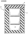
図面、特に図1を参照すると、酸化ウラン輸送用の従来の容器(全体を符号10で示す)が示してある。容器10は、酸化ウランの入った内キャニスタ12、及び内キャニスタ12を取り囲んでいるとともに着脱自在の蓋16を有する外容器14を、外壁及び蓋と内キャニスタ12との間に配置された断熱材(一般にプラスチック材料)と共に含んでいる。容器10は標準的な55ガロンドラム缶に似たもので、長年にわたって酸化ウラン用の標準的輸送容器として用いられている。
【0009】
次に図2を参照すると、本発明に従って構成された容器(全体を符号20で示す)が示してあり、容器20は外容器本体22と蓋24を含む。外容器本体22は略直方形で、図3で全体を符号32で示す複数の内容器を規則的配列で閉じこめるための、側壁26と底壁28と頂壁30とを有する。外容器本体22内には、好ましくは汚染スリーブ34によって画成される複数のキャビティが設けられ、その中に輸送のため内容器が収納される。外容器本体とその蓋について詳細に説明する前に、まず内容器について説明する。
【0010】
図3及び図4を参照すると、各内容器は底壁36、上蓋L及び円筒形側壁38からなる。底壁36並びに側壁38を構成する内壁40及び外壁42はステンレス鋼で作られる。側壁38の内壁40と外壁42の間には、好ましくは核毒物44と核減速材46を含む層状構造物が配置される。図4に最も明瞭に示されている通り、核毒物44は内壁40の外面を覆い、核減速材46は核毒物44の外面を覆う。核毒物44は好ましくは中性子吸収用のカドミウムからなり、核減速材46は好ましくはプラスチック材料(ポリエチレンなど)からなる。任意には、防火構造を追加するため、核減速材46と側壁38の外壁42との間にセラミック層48を挿入してもよい。こうして、核毒物、核減速材及び適宜セラミック層を側壁38の内壁40と外壁42の間に挿む。底壁36及び蓋Lは、好ましくは核毒物と減速材及びセラミック材料を含まないが、所望に応じてこれらの物質を含んでいてもよい。酸化ウランはペール缶Pに入れて内容器32内に配置してもよく、図3にはかかる部材Pを3つ示してある。
【0011】
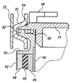
図5〜図8に、蓋Lと内容器32の側壁38との3通りの連結機構を示す。図5を参照すると、側壁38を外側に巻いて取付用ロールフランジ50が形成されている。蓋Laは、ロールフランジ50に被せるための周縁環状溝52を含んでいる。蓋Laとフランジの間には適当なシールを設けてもよい。この形態の蓋は、蓋の底面に溶接した板54で補強し得る。蓋Laを容器32に固定するため、環状C字形クランプのような適当なクランプ(図示せず)を溝52とフランジ50の周りに配置してもよい。また、容器32を密封するため、Oリングシールのような適当なシール(図示せず)をフランジ50と溝52の間に挿んでもよい。
【0012】
図6を参照すると、取付フランジ60が内容器32の側壁38に好ましくは溶接によって固定されている。取付フランジ60は、外側に向いた環状フランジ62を有している。この形態の蓋Lbは、フランジ62に被せるための半径方向外側に向いたフランジ64を有している。両フランジ62及び64の間には、Oリング型シール66が設けられる。蓋Lbは蓋の外面から突出した複数のハンドル要素68を含んでいて、クレーンのような機械で内容器32を取扱うことができる。
【0013】
図6の蓋Lbを取付フランジ60に固定するため、突き合わせフランジ62及び64の周りに略C字形の環状クランプ70を巻き付けて、両端を互いに溶接する。外側締付バンド72をクランプ70の周囲に固定するが、バンド72はその両端にねじ部品を有していて、そのねじ締め作用によってクランプ70の周りのバンド72を締付ける。
【0014】
図7及び図8を参照すると、蓋Lcはその周辺に複数のボルト穴を有する略平坦な蓋からなる。内容器側壁には、ねじ切り止まり穴76を有するフランジ74が取付けられている。環状シール78(好ましくはシリコーンゴム製のもの)が蓋Lcと取付フランジ74の間に設けられ、蓋のボルト穴及び取付フランジの止まり穴と合致する位置に開口80を有している。蓋Lcを取付フランジ74に乗せ、ボルト穴とシール穴を位置合せした後で、ボルト82を取付フランジにねじ込んで蓋を内容器に固定すればよい。
【0015】
次に図2及び図9を参照すると、前述の外容器本体22は、汚染バリアをなす複数の直立スリーブ34を含んでいる。スリーブ34は、内容器を入れるための上部開放端を有する。そこで、スリーブ34内での汚染は、汚染バリアの表面が滑らかであるので、容易に除去できる。図示した通り、内容器を収容するための外容器本体内のキャビティは規則的配列(好ましくは3×3配列)で配置される。スリーブ34を取り囲み容器本体22の容積の残部を充填しているのがプラスチック材料、好ましくは発泡ポリウレタン材料である。ポリウレタンフォームは2通りの異なる密度で容器本体内に配置される。第1フォーム90はスリーブ34間、つまりスリーブ34間の隙間に配置され、所定の密度(例えば、6〜10lb/ft3)を有する。外容器本体22の側壁26と低密度ポリウレタンフォームの内面との間には、高密度ポリウレタンフォーム92が配置される。この第2高密度フォームの密度はおよそ15lb/ft3とし得る。このフォームは容器を補強し、耐火性だけでなく衝撃吸収性をもたらす。高密度フォーム92は、図10に示す通り外容器本体22の底壁28上にも配置される。こうして、内容器は、スリーブ34収納時に、側壁26との間を高密度フォームと低密度フォームで仕切られ、底壁との間を高密度フォームで仕切られる。
【0016】
外容器の蓋24について説明する前に、やはり図2を参照すると、容器の底部には、容器の各側面に開いた一対の縦方向に延びる直方形ガイド96が設けられている。ガイド96は互いに離隔していて、その開放端を通してフォークリフトのフォークを受入れる。容器の4つの各側面にガイドが対をなして開いていることで、容器をどの側からもフォークリフトで持ち上げることができる。さらに、外容器本体22の周囲の1以上の箇所に側壁26を貫通するプラスチックプラグ98(図2及び図11)が設けられる。プラグは所定温度で融解する材料で作られ、プラグが融解すると側壁26を貫通する開口が空いて容器内部と周囲環境とが連通する。その結果、万一容器が火災のような高温に暴露されたとしても、容器内の加熱プラスチック材料から発生するガスを抜くことができ、外容器本体22の破裂を防ぐことができる。さらに、ボルトをねじ込んで蓋24を外容器本体22に固定するための、複数の突出したねじソケット100が側壁の内部に間隔をおいて設けられている。また、内容器32の長さはスリーブ34の長さを上回っており、内容器の上端部は外容器本体22の頂壁30に設けられた開口を通して突出している。
【0017】
次に図12及び図13を参照すると、蓋24は頂壁102と、頂壁102から垂下する4つの側壁104と、蓋24の角部に形成された4つの補強ガセット106とを含んでいる。蓋24は、蓋24を本体22にボルト留めするためのボルト108を差し込むための複数のボルト穴も含んでいる。
【0018】
蓋24の頂壁102の下面には、容器本体の外縁部に形成された高密度ポリウレタンフォームのような発泡プラスチック材料110が設けられている。発泡プラスチック材料110の下側には、内容器の上端部を収容するため、容器本体の頂壁30を貫通する開口に対応した位置に複数の陥凹部112(図13)が形成されている。図13に示す通り、陥凹部112は内容器の上端部の形状と相補的な形状をなす。陥凹部は、内容器をスリーブ34内に収納して蓋を容器本体22に取付けたときに内容器32が容器20内にしっかりと固定されるように、内容器の蓋のクランプ用のボルトを収容するようにも形成される。
【0019】
以上、本発明を現時点で最も実用的で好ましいと思料される実施形態について説明してきたが、本発明は、開示した実施形態のみに限定されるものではなく、請求項に記載された技術的思想及び技術的範囲に属する様々な修正及び均等な構成にも及ぶものである。
【図面の簡単な説明】
【図1】 酸化ウランの輸送に用いられる従来技術のドラム缶様バレルの断面図である。
【図2】 本発明に係る容器を示す部分切欠き断面斜視図である。
【図3】 本発明に係る内容器の一つを示す断面図である。
【図4】 本発明の内容器の積層側壁を示す拡大部分断面図である。
【図5】 本発明の好ましい形態の内容器の蓋と取付フランジとの好ましい連結部を示す部分断面図である。
【図6】 内容器の側壁と蓋との別の形態の連結部を示す断面図である。
【図7】 図8の内容器に使用される蓋の端面図である。
【図8】 蓋と内容器との別の形態の連結部を示す内容器の部分断面図である。
【図9】 外容器本体の上面図である。
【図10】 外容器本体の側面図である。
【図11】 外容器本体の側壁に設けられた融解性プラグの拡大部分断面図である。
【図12】 容器本体用の蓋の下面を示す部分切欠き底面図である。
【図13】 図12に示す蓋の側面図である。
【図14】 本発明の容器の部分切欠き側面図である。
【符号の説明】
20 容器
22 外容器本体
24 蓋
26 側壁
28 底壁
30 頂壁
32 内容器
34 スリーブ
36 底壁
38 側壁
40 内壁
42 外壁
44 核毒物
46 核減速材
48 セラミック層
50 取付フランジ
52 溝
60 取付フランジ
70 クランプ
74 取付フランジ
90 低密度ポリウレタンフォーム
92 高密度ポリウレタンフォーム
96 ガイド
98 プラスチックプラグ
100 ねじソケット
102 頂壁
104 側壁
106 補強ガセット
110 発泡プラスチック材料
112 陥凹部[0001]
TECHNICAL BACKGROUND OF THE INVENTION
The present invention relates to a container for transporting uranium oxide in a plurality of independent canisters in an outer container, and more specifically, uranium oxide per unit volume that is particularly configured to ensure critical safety. The present invention relates to a uranium oxide transport container arranged to maximize its mass.
[0002]
Currently, uranium oxide is transported in multiple independent canisters similar to conventional 55 gallon drums. Each container includes an outer metal sleeve surrounding the thermal insulation layer. The heat insulating layer surrounds and encloses a single inner canister containing uranium oxide. Such drum-like containers are typically transported in a seaburn carrier, which is basically a large trailer-sized transport carrier having a general dimension of 20 × 8 × 8. Current practice is to individually load approximately 54 drum-like containers as described above into a sea burn that meets the need to ensure critical safety (ie, the need to control neutron movement to avoid critical mass). However, the capacity of uranium oxide that can be transported in such drum canisters is relatively small, and each container must be handled individually. Therefore, it is recognized that it is necessary to transport uranium oxide more efficiently to increase the mass of uranium oxide per unit volume, thereby reducing labor and transportation costs while ensuring critical safety.
[Patent Document 1]
US Pat. No. 3,935,467 issued in January 1976 [Patent Document 2]
US Patent No. 40233317 issued in May 1977 [Patent Document 3]
US Patent No. 4560069 issued in December 1985 [Patent Document 4]
US Pat. No. 4,803,042 issued in February 1989 [Patent Document 5]
US Pat. No. 4,815,605 issued in March 1989 [Patent Document 6]
US Patent No. 5438597 issued in August 1995 [Patent Document 7]
Japanese Patent Application Laid-Open No. 61-259985 and US Patent No. 4560069 [Patent Document 8]
JP-A-01-162195 Japanese Patent Application No. 4,803,042 [Patent Document 9]
Japanese Patent Application No. 4815605, Japanese Patent Laid-Open No. 63-222299 [Patent Document 10]
Japanese Patent Application No. 08-507382, US Pat. No. 5,438,597
SUMMARY OF THE INVENTION
In an embodiment of the present invention, there is provided a new and improved multi-cavity uranium oxide transport container that accommodates a plurality of inner containers so as to guarantee critical safety and greatly increase the mass of uranium oxide per unit volume that can be transported. The Specifically, the present invention provides an outer container having a container body and a lid. The container body includes a regular array of cavities for receiving individual inner containers containing uranium oxide. In order to ensure critical safety while maximizing the mass per unit volume, each inner container has a side wall on which a nuclear poison and a nuclear moderator are stacked. For example, the stainless steel inner wall of the inner container is lined with cadmium, which is a nuclear poison, and polyethylene, which is a moderator. The moderator decelerates neutrons and captures them by cadmium poisons. A ceramic material may be laminated on the moderator and poison to increase fire resistance. The uranium oxide may be placed in a separate pail or bag and then placed in the inner container, which has a lid for sealing it.
[0004]
The cavity of the outer container preferably comprises a cylindrical sleeve made of stainless steel that stands upright from the bottom of the outer container in a regular array (eg, a preferred 3x3 array). The space between the sleeves is filled with a foamed plastic material such as polyurethane foam. The space between the outermost inner container and the outer container wall is similarly filled with a foam material such as polyurethane foam. However, the latter outer space contains a foam material having a higher density than that of the inner foam material. As a result, the high density foam material on the outer periphery of the container body forms a fire and impact resistant layer between the container body and the inner container, and the low density foamed plastic material forms an additional fire and impact resistant material. A cover plate is provided above the container body, and individual openings are provided at positions corresponding to the sleeves in the container body so that the inner container can be easily disposed in the sleeve.
[0005]
The outer container includes a lid that seals the container body in use. The lid includes a layer of high density foamed plastic material such as polyurethane on its lower surface. The plastic material is provided with a plurality of downwardly opened recesses for receiving the upper end portion of the inner container protruding through the opening of the cover plate. As a result, the inner container is completely enclosed in the outer container, and an impact resistant and fire resistant foam is provided between the inner containers and between the inner container and the outer container.
[0006]
In a preferred embodiment of the present invention, the outer container body includes a plurality of pairs of elongated, substantially rectangular pockets for inserting the forks of the forklift, and the pockets are formed so as to cross each other. In this manner, the outer container can be lifted by inserting the fork of the forklift into the pocket from any side of the container. Further, one or more plugs made of a material that can be melted at a predetermined temperature are provided on the wall of the outer container. In the event of a fire, the foamed gas of the foamed plastic material is released through the opening opened by melting the plug, preventing the container from bursting.
[0007]
In a preferred embodiment of the present invention, there is provided a uranium oxide transport container comprising an outer container and a plurality of storage inner containers arranged in a regular array spaced apart from each other in the outer container. Each storage container is made of a cylinder for containing a predetermined amount of uranium oxide, and the cylinder has a sealed top, a sealed bottom, and a cylindrical side wall in which a nuclear poison and a nuclear moderator are stacked, A transport container is provided in which the space between the storage containers and between the storage container and the outer container is filled with a plastic material.
[0008]
[Preferred Embodiment]
Referring to the drawings, and in particular to FIG. 1, a conventional container for transporting uranium oxide (shown generally at 10) is shown. The
[0009]
Referring now to FIG. 2, a container constructed in accordance with the present invention (shown generally at 20) is shown, which includes an
[0010]
Referring to FIGS. 3 and 4, each inner container includes a
[0011]
5 to 8 show three connection mechanisms between the lid L and the
[0012]
Referring to FIG. 6, a mounting
[0013]
In order to fix the lid Lb of FIG. 6 to the mounting
[0014]
Referring to FIGS. 7 and 8, the lid Lc is a substantially flat lid having a plurality of bolt holes around it. A
[0015]
2 and 9, the
[0016]
Before describing the
[0017]
Referring now to FIGS. 12 and 13, the
[0018]
A foamed
[0019]
Although the present invention has been described above with respect to embodiments that are considered to be the most practical and preferred at the present time, the present invention is not limited to only the disclosed embodiments, but the technical idea described in the claims. And various modifications and equivalent configurations belonging to the technical scope.
[Brief description of the drawings]
FIG. 1 is a cross-sectional view of a prior art drum-like barrel used for transporting uranium oxide.
FIG. 2 is a partially cutaway cross-sectional perspective view showing a container according to the present invention.
FIG. 3 is a cross-sectional view showing one of the inner containers according to the present invention.
FIG. 4 is an enlarged partial sectional view showing a laminated side wall of the inner container of the present invention.
FIG. 5 is a partial cross-sectional view showing a preferred connecting portion between the lid of the inner container and the mounting flange of the preferred embodiment of the present invention.
FIG. 6 is a cross-sectional view showing another form of connection between the side wall and the lid of the inner container.
7 is an end view of a lid used for the inner container of FIG. 8. FIG.
FIG. 8 is a partial cross-sectional view of the inner container showing another form of connection between the lid and the inner container.
FIG. 9 is a top view of the outer container body.
FIG. 10 is a side view of the outer container body.
FIG. 11 is an enlarged partial cross-sectional view of a fusible plug provided on the side wall of the outer container main body.
FIG. 12 is a partially cut-out bottom view showing the lower surface of the lid for the container main body.
13 is a side view of the lid shown in FIG. 12. FIG.
FIG. 14 is a partially cutaway side view of the container of the present invention.
[Explanation of symbols]
20
Claims (16)
前記貯蔵内容器(32)の各々が、所定量の酸化ウランを収容するための円筒を有し、該円筒が密閉頂部(L)と密閉底部(36)そして核毒物(44)と核減速材(46)とを周囲に積層した円筒形側壁(38)とを有していて、前記貯蔵内容器(32)間及び前記貯蔵内容器(32)と前記外容器(22)との間のスペースがプラスチック材料で充填されており、
前記プラスチック材料が、密度の異なる第1及び第2の別個のプラスチックフォーム材(90,92)を含んでいて、
該第1プラスチックフォーム材(90)が前記貯蔵内容器(32)間の隙間に存在し、前記第2プラスチックフォーム材(92)が前記外容器(22)を画成する側壁と前記第1プラスチックフォーム材(90)の最も外側の部分との間で前記第1プラスチックフォーム材(90)を取り囲んでいて、
前記第2プラスチックフォーム材(92)が、前記第1プラスチックフォーム材(90)よりも高い密度を有する
ことを特徴とする輸送容器(20)。Uranium oxide comprising an outer container (22) and a plurality of storage inner containers (32) arranged in a regular arrangement spaced apart from each other in the outer container (22) and spaced from the outer container (22). A transport container (20),
Each of the storage inner containers (32) has a cylinder for containing a predetermined amount of uranium oxide, and the cylinder includes a sealed top (L), a sealed bottom (36), a nuclear poison (44), and a nuclear moderator. And a cylindrical side wall (38) laminated around (46), and a space between the storage inner container (32) and between the storage inner container (32) and the outer container (22). Is filled with plastic material ,
The plastic material includes first and second separate plastic foam materials (90, 92) of different densities;
The first plastic foam material (90) exists in a gap between the storage inner containers (32), and the second plastic foam material (92) defines the outer container (22) and the first plastic. Surrounding the first plastic foam material (90) with the outermost portion of the foam material (90);
The transport container (20), wherein the second plastic foam material (92) has a higher density than the first plastic foam material (90 ).
Applications Claiming Priority (3)
| Application Number | Priority Date | Filing Date | Title |
|---|---|---|---|
| US09/315,729 US6166391A (en) | 1999-05-21 | 1999-05-21 | Uranium oxide shipping container |
| US09/315,729 | 1999-05-21 | ||
| PCT/US2000/014032 WO2000072327A1 (en) | 1999-05-21 | 2000-05-19 | Uranium oxide shipping container |
Publications (3)
| Publication Number | Publication Date |
|---|---|
| JP2003500669A JP2003500669A (en) | 2003-01-07 |
| JP2003500669A5 JP2003500669A5 (en) | 2007-07-26 |
| JP4761625B2 true JP4761625B2 (en) | 2011-08-31 |
Family
ID=23225793
Family Applications (1)
| Application Number | Title | Priority Date | Filing Date |
|---|---|---|---|
| JP2000620635A Expired - Lifetime JP4761625B2 (en) | 1999-05-21 | 2000-05-19 | Uranium oxide transport container |
Country Status (6)
| Country | Link |
|---|---|
| US (1) | US6166391A (en) |
| EP (1) | EP1101227B1 (en) |
| JP (1) | JP4761625B2 (en) |
| DE (1) | DE60015277T2 (en) |
| ES (1) | ES2230111T3 (en) |
| WO (1) | WO2000072327A1 (en) |
Families Citing this family (15)
| Publication number | Priority date | Publication date | Assignee | Title |
|---|---|---|---|---|
| US20010011711A1 (en) * | 1996-05-03 | 2001-08-09 | Graham Nicholson | Container for nuclear fuel transportation |
| US6489623B1 (en) * | 2000-11-07 | 2002-12-03 | Global Nuclear Fuel -- Americas, Llc | Shipping container for radioactive materials and methods of fabrication |
| US7028837B2 (en) * | 2001-11-23 | 2006-04-18 | Vulcan Lead, Inc. | Radiation-shielding syringe container |
| JP3799270B2 (en) * | 2001-12-21 | 2006-07-19 | 株式会社日立製作所 | Control device for switching the driving state of an automobile |
| KR100473389B1 (en) * | 2002-04-26 | 2005-03-08 | 한국수력원자력 주식회사 | A container for storing and shipping radioactive materials |
| KR100441687B1 (en) * | 2002-04-29 | 2004-07-27 | 한국원자력연구소 | A container for low level radioactive solid waste |
| JP5546138B2 (en) * | 2009-02-06 | 2014-07-09 | 三菱重工業株式会社 | Waste container and waste storage method |
| JP5357661B2 (en) * | 2009-08-20 | 2013-12-04 | 三菱重工業株式会社 | Radioactive material storage container |
| RU2491668C2 (en) * | 2011-12-05 | 2013-08-27 | Владимир Николаевич Горбачев | Container for long-term burial of hazardous wastes |
| FR3002074B1 (en) * | 2013-02-13 | 2015-03-06 | Andra | BINK FOR STORAGE OF RADIOACTIVE SUBSTANCES |
| JP5721024B2 (en) * | 2014-10-22 | 2015-05-20 | 株式会社関東技研 | Waste container |
| US9890988B2 (en) * | 2016-04-27 | 2018-02-13 | Bae Systems Plc | High temperature resistant shipping container |
| KR102078482B1 (en) | 2018-11-29 | 2020-02-17 | 한국원자력환경공단 | Disposal canister of spent nuclear fuel |
| CN112951468A (en) * | 2021-01-07 | 2021-06-11 | 上海核工程研究设计院有限公司 | Dual-purpose transport container of uranium dioxide pellet powder |
| CN114891186B (en) * | 2022-06-02 | 2024-02-02 | 陕西特种橡胶制品有限公司 | Preparation method of foam functional material for uranium dioxide pellet powder transportation equipment |
Citations (6)
| Publication number | Priority date | Publication date | Assignee | Title |
|---|---|---|---|---|
| JPS61219000A (en) * | 1985-03-25 | 1986-09-29 | 原子燃料工業株式会社 | Fuel compact housing device |
| JPH01119799A (en) * | 1987-11-04 | 1989-05-11 | Nippon Gennen Service Kk | Storage method of fissionable material |
| JPH01237499A (en) * | 1988-03-18 | 1989-09-21 | Mitsubishi Heavy Ind Ltd | Basket or radioactive material transport vessel |
| JPH05249290A (en) * | 1991-06-28 | 1993-09-28 | Westinghouse Electric Corp <We> | Flux trap neutron absorbing apparatus for nuclear fuel storage body |
| JPH09211192A (en) * | 1996-01-30 | 1997-08-15 | Sumitomo Metal Mining Co Ltd | Transportation method for nuclear fuel material |
| JP2000266890A (en) * | 1999-03-19 | 2000-09-29 | Mitsubishi Materials Corp | Storage method for nuclear fuel material and storage device of nuclear fuel material |
Family Cites Families (9)
| Publication number | Priority date | Publication date | Assignee | Title |
|---|---|---|---|---|
| US3935467A (en) * | 1973-11-09 | 1976-01-27 | Nuclear Engineering Co., Inc. | Repository for fissile materials |
| US4023317A (en) * | 1975-10-14 | 1977-05-17 | Lloyd Erwin Bettger | Building unit |
| US4535250A (en) * | 1984-05-30 | 1985-08-13 | The United States Of America As Represented By The United States Department Of Energy | Container for radioactive materials |
| US4560069A (en) * | 1985-05-02 | 1985-12-24 | Simon B Kenneth | Package for hazardous materials |
| FR2610907B1 (en) * | 1987-02-16 | 1989-07-13 | Commissariat Energie Atomique | AIR TRANSPORT CONTAINER FOR HAZARDOUS MATERIALS |
| US4803042A (en) * | 1987-11-23 | 1989-02-07 | Westinghouse Electric Corp. | Nuclear reactor core component shipping container |
| JPH02222866A (en) * | 1989-02-09 | 1990-09-05 | Toshiba Corp | Spent fuel basket |
| US5438597A (en) * | 1993-10-08 | 1995-08-01 | Vectra Technologies, Inc. | Containers for transportation and storage of spent nuclear fuel |
| GB9415373D0 (en) * | 1994-07-29 | 1994-09-28 | British Nuclear Fuels Plc | Overpacks for drums |
-
1999
- 1999-05-21 US US09/315,729 patent/US6166391A/en not_active Expired - Lifetime
-
2000
- 2000-05-19 WO PCT/US2000/014032 patent/WO2000072327A1/en active IP Right Grant
- 2000-05-19 ES ES00932687T patent/ES2230111T3/en not_active Expired - Lifetime
- 2000-05-19 JP JP2000620635A patent/JP4761625B2/en not_active Expired - Lifetime
- 2000-05-19 EP EP20000932687 patent/EP1101227B1/en not_active Expired - Lifetime
- 2000-05-19 DE DE60015277T patent/DE60015277T2/en not_active Expired - Lifetime
Patent Citations (6)
| Publication number | Priority date | Publication date | Assignee | Title |
|---|---|---|---|---|
| JPS61219000A (en) * | 1985-03-25 | 1986-09-29 | 原子燃料工業株式会社 | Fuel compact housing device |
| JPH01119799A (en) * | 1987-11-04 | 1989-05-11 | Nippon Gennen Service Kk | Storage method of fissionable material |
| JPH01237499A (en) * | 1988-03-18 | 1989-09-21 | Mitsubishi Heavy Ind Ltd | Basket or radioactive material transport vessel |
| JPH05249290A (en) * | 1991-06-28 | 1993-09-28 | Westinghouse Electric Corp <We> | Flux trap neutron absorbing apparatus for nuclear fuel storage body |
| JPH09211192A (en) * | 1996-01-30 | 1997-08-15 | Sumitomo Metal Mining Co Ltd | Transportation method for nuclear fuel material |
| JP2000266890A (en) * | 1999-03-19 | 2000-09-29 | Mitsubishi Materials Corp | Storage method for nuclear fuel material and storage device of nuclear fuel material |
Also Published As
| Publication number | Publication date |
|---|---|
| DE60015277D1 (en) | 2004-12-02 |
| EP1101227A1 (en) | 2001-05-23 |
| US6166391A (en) | 2000-12-26 |
| ES2230111T3 (en) | 2005-05-01 |
| JP2003500669A (en) | 2003-01-07 |
| DE60015277T2 (en) | 2006-02-02 |
| EP1101227B1 (en) | 2004-10-27 |
| WO2000072327A1 (en) | 2000-11-30 |
Similar Documents
| Publication | Publication Date | Title |
|---|---|---|
| JP4761625B2 (en) | Uranium oxide transport container | |
| US4535250A (en) | Container for radioactive materials | |
| US10026514B2 (en) | Canister apparatus and basket for transporting, storing and/or supporting spent nuclear fuel | |
| EP0673541B1 (en) | Container for transportation and storage of nuclear fuel assemblies | |
| KR101123652B1 (en) | Apparatus, system and method for storing high level waste | |
| KR101059545B1 (en) | Container for nuclear fuel transportation | |
| JP2004037450A (en) | Device and method for maximizing radiation shield during transportation procedure for spent nuclear fuel | |
| JPH04357498A (en) | Storage cask for radioactive structure and manufacture thereof | |
| CA1214288A (en) | Device for handling and protecting storage containers for radioactive materials | |
| US4626402A (en) | Apparatus for the storage and transport of radioactive materials | |
| US8616404B1 (en) | Shipping container | |
| RU2284066C2 (en) | Packing device for shipping uranium-containing nuclear fuel in bulk | |
| JP2003524786A (en) | Double vessel vessel for transport and storage of radioactive materials | |
| US5998800A (en) | Pipe overpack container for trasuranic waste storage and shipment | |
| CN213519287U (en) | Nuclear fuel transport container shell with buffering heat absorption and moderating functions | |
| JP4727229B2 (en) | Containers for storage / transport of unirradiated radioactive material such as nuclear fuel assemblies | |
| US5848112A (en) | Method of transporting nuclear fuel substance | |
| US10186336B2 (en) | Packaging design for storage, transportation, and disposal of disused radiological sources | |
| US20040141579A1 (en) | Storage/transport container for damaged nuclear-fuel elements | |
| KR102398977B1 (en) | Anti-shock tube container for radioactive waste matter | |
| CN113168926A (en) | Spent nuclear fuel tank | |
| JP6098105B2 (en) | Storage structure for electricity storage devices | |
| KR20120040324A (en) | Handling vessel for tritium | |
| JP2000321397A (en) | Waste vessel for geologic disposal of heat exothermic tru contaminated radioactive waste | |
| JP2989441B2 (en) | Radioactive gas transport container |
Legal Events
| Date | Code | Title | Description |
|---|---|---|---|
| A521 | Written amendment |
Free format text: JAPANESE INTERMEDIATE CODE: A523 Effective date: 20070515 |
|
| A621 | Written request for application examination |
Free format text: JAPANESE INTERMEDIATE CODE: A621 Effective date: 20070515 |
|
| A131 | Notification of reasons for refusal |
Free format text: JAPANESE INTERMEDIATE CODE: A131 Effective date: 20100817 |
|
| A601 | Written request for extension of time |
Free format text: JAPANESE INTERMEDIATE CODE: A601 Effective date: 20101116 |
|
| RD02 | Notification of acceptance of power of attorney |
Free format text: JAPANESE INTERMEDIATE CODE: A7422 Effective date: 20101116 |
|
| RD04 | Notification of resignation of power of attorney |
Free format text: JAPANESE INTERMEDIATE CODE: A7424 Effective date: 20101116 |
|
| A602 | Written permission of extension of time |
Free format text: JAPANESE INTERMEDIATE CODE: A602 Effective date: 20101126 |
|
| A521 | Written amendment |
Free format text: JAPANESE INTERMEDIATE CODE: A523 Effective date: 20110216 |
|
| TRDD | Decision of grant or rejection written | ||
| A01 | Written decision to grant a patent or to grant a registration (utility model) |
Free format text: JAPANESE INTERMEDIATE CODE: A01 Effective date: 20110510 |
|
| A61 | First payment of annual fees (during grant procedure) |
Free format text: JAPANESE INTERMEDIATE CODE: A61 Effective date: 20110607 |
|
| FPAY | Renewal fee payment (event date is renewal date of database) |
Free format text: PAYMENT UNTIL: 20140617 Year of fee payment: 3 |
|
| R150 | Certificate of patent or registration of utility model |
Ref document number: 4761625 Country of ref document: JP Free format text: JAPANESE INTERMEDIATE CODE: R150 Free format text: JAPANESE INTERMEDIATE CODE: R150 |
|
| FPAY | Renewal fee payment (event date is renewal date of database) |
Free format text: PAYMENT UNTIL: 20140617 Year of fee payment: 3 |
|
| R250 | Receipt of annual fees |
Free format text: JAPANESE INTERMEDIATE CODE: R250 |
|
| R250 | Receipt of annual fees |
Free format text: JAPANESE INTERMEDIATE CODE: R250 |
|
| R250 | Receipt of annual fees |
Free format text: JAPANESE INTERMEDIATE CODE: R250 |
|
| R250 | Receipt of annual fees |
Free format text: JAPANESE INTERMEDIATE CODE: R250 |
|
| R250 | Receipt of annual fees |
Free format text: JAPANESE INTERMEDIATE CODE: R250 |
|
| R250 | Receipt of annual fees |
Free format text: JAPANESE INTERMEDIATE CODE: R250 |
|
| EXPY | Cancellation because of completion of term |