JP4759241B2 - Lens barrel and photographing device - Google Patents
Lens barrel and photographing device Download PDFInfo
- Publication number
- JP4759241B2 JP4759241B2 JP2004271470A JP2004271470A JP4759241B2 JP 4759241 B2 JP4759241 B2 JP 4759241B2 JP 2004271470 A JP2004271470 A JP 2004271470A JP 2004271470 A JP2004271470 A JP 2004271470A JP 4759241 B2 JP4759241 B2 JP 4759241B2
- Authority
- JP
- Japan
- Prior art keywords
- cam groove
- cam
- zoom
- end region
- movable
- Prior art date
- Legal status (The legal status is an assumption and is not a legal conclusion. Google has not performed a legal analysis and makes no representation as to the accuracy of the status listed.)
- Expired - Fee Related
Links
Images


Classifications
-
- G—PHYSICS
- G02—OPTICS
- G02B—OPTICAL ELEMENTS, SYSTEMS OR APPARATUS
- G02B7/00—Mountings, adjusting means, or light-tight connections, for optical elements
- G02B7/02—Mountings, adjusting means, or light-tight connections, for optical elements for lenses
- G02B7/026—Mountings, adjusting means, or light-tight connections, for optical elements for lenses using retaining rings or springs
Description
本発明は、ズームレンズ鏡筒およびこれを用いたスチルカメラ、デジタルスチルカメラ、ビデオカメラ等の光学機器に関するものである。 The present invention relates to a zoom lens barrel and optical equipment such as a still camera, a digital still camera, and a video camera using the same.
従来、デジタルカメラなどの撮影装置では、撮影状態で撮影装置本体からレンズ鏡筒を繰り出し、撮影を行わない携帯時(非撮影時)にレンズ鏡筒を撮影装置本体内に収容させるいわゆる沈胴レンズ鏡筒が用いられている。 2. Description of the Related Art Conventionally, in a photographing apparatus such as a digital camera, a so-called collapsible lens mirror is used in which a lens barrel is extended from a photographing apparatus main body in a photographing state, and the lens barrel is housed in the photographing apparatus main body when not photographing. A cylinder is used.
このようなレンズ鏡筒としては、特許文献1に開示されたものがある。特許文献1のレンズ鏡筒は、移動カム環にレンズ移動用のカム溝を設け、固定筒に沈胴用のカム溝を設け、移動カム環を回転駆動して固定筒の沈胴用のカム溝に沿って回転させ光軸方向に移動させることにより、沈胴状態から撮影状態にさせ、この撮影状態の位置で移動カム環を光軸方向に移動させずに回転させることで可動レンズをレンズ移動用のカム溝に沿って光軸方向に移動させてズームを行う構成となっている。
ところで、近年、デジタルカメラなどの撮影装置では、装置本体の小型化、薄型化が望まれており、レンズ鏡筒を撮影装置本体内に収容(沈胴)させる構成の場合、収容(沈胴)でのレンズ鏡筒の全長短縮が必要とされている。 By the way, in recent years, in an imaging apparatus such as a digital camera, it is desired to reduce the size and thickness of the apparatus body. In the case of a configuration in which the lens barrel is accommodated (collapsed) in the imaging apparatus body, There is a need to reduce the overall length of the lens barrel.
ここで、上記の特許文献1のレンズ鏡筒では、撮影状態では移動カム環を光軸方向に移動させずに回転させることで可動レンズをレンズ移動用のカム溝に沿って光軸方向に移動させてズームを行う構成であるため、可動レンズの移動量(ズーム量)に応じてレンズ移動用のカム溝を形成する必要があり、これに合わせて移動カム環の光軸方向の全長を長くとる必要があり、撮影装置本体内に収容された沈胴時でのレンズ鏡筒の全長が長くなってしまう。また最前の可動レンズが、ズーム領域における広角端と望遠端との光軸上での位置が異なる(最前の可動レンズの広角端と望遠端との繰り出し量が異なる)光学系では、さらに、レンズ移動用のカム溝が長くなり、移動カム環の光軸方向の全長がさらに長くなる。また、カム軌跡の変化が急になるため、移動カム環を回転駆動させるためのトルク負荷が大きくなってしまう。
Here, in the above-described lens barrel of
本発明は、移動カム環(移動筒)の光軸方向の全長を短くすることで、光軸方向の全長が短縮されたレンズ鏡筒を提供することを目的としている。 It is an object of the present invention to provide a lens barrel in which the total length in the optical axis direction is shortened by shortening the total length in the optical axis direction of the movable cam ring (movable cylinder).
上記の目的を達成するために、本発明は、撮影装置本体に固定される固定筒と、ズームレンズ保持枠を光軸方向に移動可能に保持する移動筒とを備えるレンズ鏡筒であって、
前記固定筒は、前記移動筒に設けられた第1のフォロアピンと係合する第1のカム溝を有し、前記移動筒は、前記ズームレンズ保持枠に設けられた第2のフォロアピンと係合する第2のカム溝を有し、
ワイド端領域及びテレ端領域を含むズーム領域内での前記第1のカム溝は、前記固定筒を展開した場合、線形形状であり、
前記固定筒は、前記移動筒に設けられた第1の突起部と当接する第2の突起部を有し、前記固定筒を展開した場合、前記第2の突起部は、前記ワイド端領域及び前記テレ端領域を含むズーム領域内での前記第1のカム溝に沿って形成されており、
非撮影時、前記移動筒は、前記固定筒に対して沈胴した沈胴位置にあり、
撮影を行う際、前記移動筒は、前記沈胴位置から前記ズーム領域へ繰出された後、前記ズーム領域内で前記光軸方向に移動し、
前記第1のカム溝のワイド端領域及びテレ端領域は、前記固定筒を展開した場合、等リード形状であり、
前記第2のカム溝のワイド端領域は、前記第1のカム溝のワイド端領域の等リード形状に対してカムリフトが逆向きの等リード形状であり、
前記第2のカム溝のテレ端領域は、前記第1のカム溝のテレ端領域の等リード形状に対してカムリフトが逆向きの等リード形状であることを特徴とする。
In order to achieve the above object, the present invention provides a lens barrel including a fixed barrel fixed to the photographing apparatus body and a movable barrel that holds the zoom lens holding frame so as to be movable in the optical axis direction.
The fixed cylinder has a first cam groove that engages with a first follower pin provided on the movable cylinder, and the movable cylinder engages with a second follower pin provided on the zoom lens holding frame. Having a second cam groove,
The first cam groove in the zoom region including the wide end region and the tele end region has a linear shape when the fixed cylinder is expanded ,
The fixed cylinder has a second protrusion that contacts the first protrusion provided on the movable cylinder. When the fixed cylinder is expanded, the second protrusion is Formed along the first cam groove in the zoom region including the tele end region,
At the time of non-photographing, the moving cylinder is in a retracted position retracted with respect to the fixed cylinder,
When shooting, the moving cylinder is moved from the retracted position to the zoom area, and then moves in the optical axis direction within the zoom area.
The wide end region and the tele end region of the first cam groove have an equal lead shape when the fixed cylinder is deployed,
The wide end region of the second cam groove has an equal lead shape in which the cam lift is opposite to the equal lead shape of the wide end region of the first cam groove,
The tele end region of the second cam groove has an equal lead shape in which the cam lift is opposite to the equal lead shape of the tele end region of the first cam groove.
なお、本発明のレンズ鏡筒は、カメラなどの撮影装置に用いることができる。 The lens barrel of the present invention can be used for a photographing apparatus such as a camera.
本発明によれば、移動カム環(移動筒)の光軸方向の全長を短くすることで、光軸方向の全長が短縮されたレンズ鏡筒を提供することができる。 According to the present invention, it is possible to provide a lens barrel whose overall length in the optical axis direction is shortened by shortening the overall length of the movable cam ring (movable barrel) in the optical axis direction.
以下を本発明の実施例について図面を参照しながら説明する。 Embodiments of the present invention will be described below with reference to the drawings.
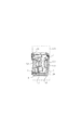
図1は本発明を適用した撮影装置(デジタルカメラ、ビデオカメラ)のレンズ鏡筒の分解斜視図である。また図2、図3、図4はレンズ鏡筒の断面図であり、図2は沈胴状態、図3はワイド(広角)状態、図4はテレ(望遠)状態を示している。 FIG. 1 is an exploded perspective view of a lens barrel of a photographing apparatus (digital camera, video camera) to which the present invention is applied. 2, 3 and 4 are sectional views of the lens barrel. FIG. 2 shows a retracted state, FIG. 3 shows a wide (wide angle) state, and FIG. 4 shows a tele (telephoto) state.
これらの図において、本発明のレンズ鏡筒におけるズーム光学系は、凹凸凸の3群リヤフォーカスであり、1は第1群の移動レンズ群L1を保持する第1の保持枠(レンズ保持枠)であり、外周側面には3箇所にボス部1bが設けられ、各ボス部1bにはそれぞれテーパ部を持つフォロアピン1aが圧入固定されている。2は第2群の移動レンズ群L2を保持する第2の保持枠(レンズ保持枠)であり、外周側面にテーパ部を持つ2本のフォロア部2aが一体的に形成されると共に、光軸中心に向かって移動可能に設けられた1個の可動フォロア2bが設けられている。これら3個のフォロアは、第2の保持枠2の外周部に等間隔で配置されている。可動フォロア2bは、不図示の圧縮ばねにより付勢されており、これによって機械的な間隔を片寄せで精度を維持するようになっている。 In these drawings, the zoom optical system in the lens barrel of the present invention is an uneven convex third group rear focus, and 1 is a first holding frame (lens holding frame) that holds the moving lens group L1 of the first group. The boss portions 1b are provided at three locations on the outer peripheral side surface, and follower pins 1a each having a tapered portion are press-fitted and fixed to each boss portion 1b. Reference numeral 2 denotes a second holding frame (lens holding frame) that holds the moving lens group L2 of the second group. The two follower portions 2a each having a tapered portion on the outer peripheral side surface are integrally formed, and the optical axis. One movable follower 2b provided so as to be movable toward the center is provided. These three followers are arranged at equal intervals on the outer periphery of the second holding frame 2. The movable follower 2b is urged by a compression spring (not shown), thereby maintaining the accuracy by shifting the mechanical interval.
3は第2の保持枠2に固定保持された絞りユニットであり、絞り駆動部3aとシャッター駆動部3bを別々に有している。絞り駆動部3aは、複数の絞り羽根を駆動し、絞り開口形状を変化させる。シャッター駆動部3bは、2枚の旋回羽根を駆動し開放から全閉へのシャッター動作を行う。
4は第3群の移動レンズ群L3を保持する第3の保持枠であり、ガイドバー8とカバー9に一体で設けられた案内軸(不図示)とに案内されると共に、光軸方向の位置は、第3の移動枠4の腕部4aに光軸方向に位置決めされ回転自在に取り付けられたラック部材5に規制されている。7はステッピングモータであり出力スクリュー7aを駆動する。ステッピングモータ7は、上記カバー9にビス固定されている。出力スクリュー7aの先端は、カバー9に一体で形成された軸受け部(不図示)により回転可能に保持されている。ラック部材5は、バネ6の力によりモータ7の出力スクリュー7aに圧接され、モータ7の回転により光軸方向に駆動される。これにより第3の保持枠4が光軸方向に移動される。 Reference numeral 4 denotes a third holding frame for holding the third lens group L3. The third holding frame is guided by a guide shaft 8 (not shown) provided integrally with the guide bar 8 and the cover 9, and in the optical axis direction. The position is regulated by a rack member 5 that is positioned in the optical axis direction on the arm portion 4a of the third moving frame 4 and is rotatably attached. A stepping motor 7 drives the output screw 7a. The stepping motor 7 is screwed to the cover 9. The distal end of the output screw 7a is rotatably held by a bearing portion (not shown) formed integrally with the cover 9. The rack member 5 is pressed against the output screw 7 a of the motor 7 by the force of the spring 6, and is driven in the optical axis direction by the rotation of the motor 7. As a result, the third holding frame 4 is moved in the optical axis direction.
10は、鏡筒ユニットの基部となるCCDホルダーであり、その前端部にビス(不図示)止めにより固定される固定鏡筒11と共に、鏡筒ユニットの構造体を形成している。上記カバー9は、CCDホルダー10にビス(不図示)にて固定される。12は、CCDホルダー10に固定されたフォトインタラプタであり、第3の移動枠4に一体形成されたスリット板部4bが、上記フォトインタラプタ12のスリット部に退進可能な位置に配置されている。CCDホルダー10には、CCDやCMOSなどの撮像素子101およびローパスフィルター102が固定保持されている。なお、図2において、100はデジタルカメラ、ビデオカメラなどの撮影装置本体(光学機器)であり、固定鏡筒11を固定する構成となっている。
固定鏡筒11(固定筒)の内径部には、カム溝11aが形成され、このカム溝11aに、移動カム環13(移動筒)に圧入固定されている金属製のフォロアピン(第1のフォロアピン)13aが嵌合(係合)し、移動カム環13がカム溝(第1のカム溝)11aに沿って回動することで、移動カム環13は光軸方向に繰出される。移動カム環13は、カム溝11aのカムリフト(カムの傾き)により、沈胴動作領域および撮影を行う際のズーム領域において光軸方向に移動される。
A
固定鏡筒11には、ズームモータ14と、その出力軸に取り付けられたギヤ17と、その出力を減速するギヤ列15および出力ギヤ16が組み込まれており、移動カム環13の外周部に形成されたギヤ歯13bにズームモータ14の回転をギヤ列15および出力ギヤ16を介して伝達することにより、移動カム環13は、回転駆動され、光軸方向に移動される。ギヤ17には、ズームモータ14の回転を検知するための羽根17aが3枚設けられており、その羽根がスリット部を遮断するように、フォトインタラプタ18,19が150度の角度で配置されている。
The fixed
20はファインダー用カムプレートであり、表面にはファインダーユニット21のファインダーレンズをズーム駆動するためのテーパカム溝20a、20bが形成されている。ファインダーカムプレート20は、固定鏡筒11の外周部に沿って回転可能となっており、移動カム環13に連動してズーミングする。
A
移動カム環13の内部には、直進ガイド筒22が回転自在に嵌合されており、直進ガイド筒22に設けられた突起22aは、固定鏡筒11に設けられた溝部11aに嵌められて、直進ガイド筒22が固定鏡筒11に対して回転しない様になっている。また、直進ガイド筒22に設けられた3つの突起22bは、移動カム環13の内面に設けられた円周方向の溝部13cに嵌合されている。この為、直進ガイド筒22と移動カム環13は、回転自在でありながら、光軸方向には一体となって移動する。
A rectilinear guide tube 22 is rotatably fitted inside the
第1の保持枠1に設けられた金属製のフォロアピン(第2のフォロアピン)1aは、移動カム環13のカム溝(第2のカム溝)13dに嵌合(係合)し、直進ガイド筒22の直動溝22cは、第1の保持枠1に設けられたボス部1bと嵌合している。この直動溝22cにより、回転方向に第1の保持枠1が回転することが制限されており、移動カム環13が回動すると、第1の保持枠1は、光軸方向に移動(繰出)される。また、第2の保持枠2も同様に、移動カム環13のカム溝(第2のカム溝)13eと直進ガイド筒22の直動溝22dにフォロア部(第2のフォロアピン)2aが嵌合(係合)して規制されている。従って、移動カム環13が回動すると、第2の保持枠2は、カム溝13eに沿って光軸方向に移動(繰出)される。
A metal follower pin (second follower pin) 1 a provided on the
図5は、固定鏡筒11の内周面を示す展開図で、固定鏡筒11の内側に設けられたカム溝11aに沿って形成された受け部(第2の突起部)11bと、移動カム環13の外周部に設けられた鍔部(第1の突起部)13fの関係を示す。固定鏡筒11のカム溝11aは、沈胴動作領域11a1、ズーム領域11a3を有し、さらにズーム領域11a3内にはワイド端領域11a2、テレ端領域11a4を有している。
FIG. 5 is a development view showing the inner peripheral surface of the fixed
移動カム環13が固定鏡筒11に対して回転されて、フォロアピン13aが固定鏡筒11のカム溝11aの沈胴位置(非撮影時に移動筒が固定筒に対して沈胴した位置)からワイド端領域11a2までの沈胴動作領域11a1内で移動する間は、鍔部13fは固定鏡筒11に設けられた受け部11bよりも撮像面側(撮影装置本体側)に位置している。
The
さらに移動カム環13が固定鏡筒11に対して回転されて、フォロアピン13aがズーム領域11a3内で移動する間では、カム溝11a(ワイド端領域11a2からテレ端領域11a4までの間)および受け部11bは、等リード形状(カムリフトが等しい線形形状)に変化している。すなわち、カム溝11aおよび受け部11bは、光軸方向に垂直な面に対して、撮影装置本体とは反対の側に傾斜しており、移動カム環13は、移動カム環13の回転数に比例した移動量で、光軸方向に移動する。このとき、鍔部13fは受け部11bより対物側(撮影装置本体とは反対側)に位置しており、鍔部13fと受け部11bとが当接可能となっている。
Further, the
上記のように、カム溝11aは、沈胴カム領域11a1で移動カム環13が沈胴位置から撮影位置(ズーム領域)にいたるまでの間で光軸方向に移動する第1のリフトを有し、ワイド端領域11a2からテレ端領域11a4までのズーム領域内で、移動カム環13が光軸方向に移動する第2のリフト(等リード形状)を有している。
As described above, the
従って、撮影可能状態(ズーム領域)において、衝撃的な外力が第1の保持枠1および移動カム環13に働いた場合、移動カム環13の鍔部13fが固定鏡筒11の受け部11bに当接し、受け部11bが外圧を受けて吸収することとなり、移動カム環13のフォロアピン13aが、固定鏡筒11のカム溝11aから脱落するのを防止することができる。
Accordingly, when a shocking external force is applied to the
ズーム初期位置は、図1に示すように、直進ガイド筒22の不図示の遮光板部が、CCDホルダー10に固定されたフォトインタラプタ23を遮光する事で検出している。ギヤ17には、ズームモータ14の回転を検知するための羽根17aが3枚設けられており、その羽根17aがフォトインタラプタ18,19のスリット部を遮断する事により、ズームモータ14の回転をパルス波形に変換し、そのパルス波形をカウントすることで、ズームモータ14の回転数を検出している。この回転数は、先に述べたズーム初期位置が基準となり、ズームポジションを決めている。
As shown in FIG. 1, the initial zoom position is detected by shielding a photo interrupter 23 fixed to the
図6は、移動カム環13の内周面を示す展開図で、移動カム環13には、第1の保持枠1を光軸方向に移動させるための1群カム溝13dと第2の保持枠2を光軸方向に移動させるための2群カム溝13eが形成されている。
FIG. 6 is a development view showing the inner peripheral surface of the
1群カム溝13dは、沈胴動作領域13d1、ズーム領域13d3を有し、さらにズーム領域13d3内にはワイド端領域13d2、テレ端領域13d4を有している。また、2群カム溝13eは、沈胴動作領域13e1、ズーム領域13e3を有し、さらにズーム領域13e3内にはワイド端領域13e2、テレ端領域13e4を有している。
The first
1群カム溝13dのワイド端領域13d2および2群カム溝13eのワイド端領域13e2は、固定鏡筒11のカム溝11aのワイド端領域11a2の等リード形状に対してカムリフトが逆向きの等リード形状に形成されている。すなわち、第1の保持枠1および第2の保持枠2は、移動カム環13に対して、移動カム環13の移動方向とは逆向きに、移動カム環13の移動量と同じ量移動し、この範囲では第1の保持枠1および第2の保持枠2は、固定鏡筒11に対して光軸方向に移動しない一定位置(ワイド端位置)に保持される状態となる。
The wide end region 13d2 of the first
また、1群カム溝13dのテレ側カム領域13d4および2群カム溝13eのテレ側カム領域13e4は、固定鏡筒11のカム溝11aのテレ端領域11a4の等リード形状に対してカムリフトが逆向きの等リード形状に形成されている。すなわち、第1の保持枠1および第2の保持枠2は、移動カム環13に対して、移動カム環13の移動方向とは逆向きに、移動カム環13の移動量と同じ量移動し、この範囲では第1の保持枠1および第2の保持枠2は、固定鏡筒11に対して光軸方向に移動しない一定位置(テレ端位置)に保持される状態となる。
The tele-side cam region 13d4 of the first
上記ズーム初期位置からのステップズレ(設計値との差)をこの範囲(第1の保持枠1および第2の保持枠2が、固定鏡筒11に対して光軸方向に移動しないテレ端位置あるいはワイド端位置に保持される範囲)で吸収し、ズーム領域内のテレ端位置およびワイド端位置を正確に設定することができる。
The step shift (difference from the design value) from the initial zoom position is within this range (the tele end position where the
固定鏡筒11の撮影可能範囲(ズーム領域)でのカム溝11aは、上記のように、等リード形状に形成されており、移動カム環13のズーム領域(変極点を含む)での1群カム溝13dおよび2群カム溝13eのカムリフトを、固定鏡筒11のカム溝11aの等リード形状に振分けることができるので、移動カム環13のカムリフトを緩やかに傾斜させて設計することができる。従って、移動カム環13の光軸方向の全長を短くすることができ、沈胴時におけるレンズ鏡筒の光軸方向の全長を短縮することができる。
The
以上説明したように上記の実施例では、固定鏡筒の内径に形成したカムの撮影可能領域(ズーム領域)を等リード形状とすることで、移動カム環のカム軌跡の変化を緩やかにしている。さらに、ズーム領域内のワイド端位置とテレ端位置でレンズ保持枠の光軸位置が異なる場合、固定鏡筒のカムリフト量で差し引いた差分だけを移動カム環のカムリフト量とすれば良いので、沈胴時におけるレンズ鏡筒の全長を短縮することができる。 As described above, in the above-described embodiment, the cam trajectory of the movable cam ring is moderately changed by making the shootable region (zoom region) of the cam formed on the inner diameter of the fixed barrel an equal lead shape. . Further, when the optical axis position of the lens holding frame is different between the wide end position and the tele end position in the zoom region, only the difference subtracted by the cam lift amount of the fixed barrel needs to be the cam lift amount of the moving cam ring. The total length of the lens barrel at the time can be shortened.
また、固定鏡筒の内径に形成したカムの撮影可能領域を、等リード形状とし、これに沿った受け部(第2の突起部)を固定鏡筒の内径に設け、受け部と当接可能で、かつ、撮影可能領域で受け部より前玉側に鍔部(第1の突起部)を移動カム環に設けたことで、鏡筒に衝撃などの外力が作用しても、移動カム環のフォロアが固定鏡筒のカム溝から脱落することが有効に防止され、ズーム機能が損なわれるのを防止することが可能となる。 In addition, the shootable area of the cam formed on the inner diameter of the fixed barrel is made into an equal lead shape, and a receiving portion (second protrusion) along this is provided on the inner diameter of the fixed barrel so that it can come into contact with the receiving portion In addition, even when an external force such as an impact acts on the lens barrel, the moving cam ring is provided with a collar (first protrusion) on the moving cam ring on the front lens side of the receiving part in the shootable region. It is possible to effectively prevent the follower from falling off the cam groove of the fixed barrel, and to prevent the zoom function from being impaired.
さらに、移動カム環の撮影可能領域のワイド端およびテレ端には、固定鏡筒のカムリフト量を打ち消すような等リード形状のカムを移動カム環の内径に設け、テレ端およびワイド端で、第1移動レンズ群および第2移動レンズ群の光軸位置を変化させない領域を作り出すことで、ズームリセット位置ズレを補正し、ズームのテレ端およびワイド端の位置を正確に設定することができる。 Furthermore, equi-leaded cams that cancel the cam lift amount of the fixed lens barrel are provided on the inner diameter of the moving cam ring at the wide end and the tele end of the movable cam ring in the imageable region. By creating a region in which the optical axis positions of the first moving lens group and the second moving lens group are not changed, it is possible to correct the zoom reset position shift and accurately set the zoom tele end and wide end positions.
なお、上述した実施例では、移動カム環を光軸方向に移動させるための、固定鏡筒の撮影領域でのカムを線形の等リード形状のカムとし、移動カム環のワイド端領域およびテレ端領域を、上記の等リード形状とはカムシフトが逆向きの等リード形状のカムとして、第1移動レンズ群および第2移動レンズ群がワイド端位置あるいはテレ端位置で保持(移動しない)される構成としたが、固定鏡筒および移動カム環の各カムの形状は特に等リード形状に限定されものではなく、カムリフト量が変化する形状あるいは非線形状でもよく、固定鏡筒および移動カム環の各カムによって、撮影領域(ズーム領域)のワイド側およびテレ側では、可動レンズがワイド端位置およびテレ端位置を保持(移動しない)される構成であればよい。 In the above-described embodiment, the cam in the imaging region of the fixed barrel for moving the movable cam ring in the optical axis direction is a linear, equi-leaded cam, and the wide end region and the tele end of the movable cam ring. A structure in which the first moving lens group and the second moving lens group are held (not moved) at the wide end position or the tele end position as a cam having an equal lead shape in which the cam shift is opposite to the above equal lead shape. However, the shape of each cam of the fixed barrel and the moving cam ring is not particularly limited to an equal lead shape, and the cam lift amount may be changed or non-linear. Accordingly, the movable lens may be configured to hold (do not move) the wide end position and the tele end position on the wide side and the tele side of the photographing area (zoom area).
L1 第1群の移動レンズ群
L2 第2群の移動レンズ群
1 第1の保持枠
2 第2の保持枠
11 固定鏡筒
11a カム溝
11a2 ワイド端領域
11a3 ズーム領域
11a4 テレ端領域
11b 受け部
13 移動カム環
13d 1群カム溝
13d2 ワイド端領域
13d3 ズーム領域
13d4 テレ端領域
13e 2群カム溝
13e2 ワイド端領域
13e3 ズーム領域
13e4 テレ端領域
13f 鍔部
L1 Moving lens group of the first group L2 Moving lens group of the
Claims (2)
前記固定筒は、前記移動筒に設けられた第1のフォロアピンと係合する第1のカム溝を有し、前記移動筒は、前記ズームレンズ保持枠に設けられた第2のフォロアピンと係合する第2のカム溝を有し、
ワイド端領域及びテレ端領域を含むズーム領域内での前記第1のカム溝は、前記固定筒を展開した場合、線形形状であり、
前記固定筒は、前記移動筒に設けられた第1の突起部と当接する第2の突起部を有し、前記固定筒を展開した場合、前記第2の突起部は、前記ワイド端領域及び前記テレ端領域を含むズーム領域内での前記第1のカム溝に沿って形成されており、
非撮影時、前記移動筒は、前記固定筒に対して沈胴した沈胴位置にあり、
撮影を行う際、前記移動筒は、前記沈胴位置から前記ズーム領域へ繰出された後、前記ズーム領域内で前記光軸方向に移動し、
前記第1のカム溝のワイド端領域及びテレ端領域は、前記固定筒を展開した場合、等リード形状であり、
前記第2のカム溝のワイド端領域は、前記第1のカム溝のワイド端領域の等リード形状に対してカムリフトが逆向きの等リード形状であり、
前記第2のカム溝のテレ端領域は、前記第1のカム溝のテレ端領域の等リード形状に対してカムリフトが逆向きの等リード形状であることを特徴とするレンズ鏡筒。 A lens barrel including a fixed barrel fixed to the imaging apparatus main body and a movable barrel that holds the zoom lens holding frame so as to be movable in the optical axis direction;
The fixed cylinder has a first cam groove that engages with a first follower pin provided on the movable cylinder, and the movable cylinder engages with a second follower pin provided on the zoom lens holding frame. Having a second cam groove,
The first cam groove in the zoom region including the wide end region and the tele end region has a linear shape when the fixed cylinder is expanded ,
The fixed cylinder has a second protrusion that contacts the first protrusion provided on the movable cylinder. When the fixed cylinder is expanded, the second protrusion is Formed along the first cam groove in the zoom region including the tele end region,
At the time of non-photographing, the moving cylinder is in a retracted position retracted with respect to the fixed cylinder,
When shooting, the moving cylinder is moved from the retracted position to the zoom area, and then moves in the optical axis direction within the zoom area.
The wide end region and the tele end region of the first cam groove have an equal lead shape when the fixed cylinder is deployed,
The wide end region of the second cam groove has an equal lead shape in which the cam lift is opposite to the equal lead shape of the wide end region of the first cam groove,
The telephoto end region of the second cam groove has an equal lead shape in which the cam lift is opposite to the equal lead shape of the tele end region of the first cam groove .
Priority Applications (2)
| Application Number | Priority Date | Filing Date | Title |
|---|---|---|---|
| JP2004271470A JP4759241B2 (en) | 2003-10-27 | 2004-09-17 | Lens barrel and photographing device |
| US10/970,926 US7038859B2 (en) | 2003-10-27 | 2004-10-21 | Lens barrel and imaging device |
Applications Claiming Priority (3)
| Application Number | Priority Date | Filing Date | Title |
|---|---|---|---|
| JP2003365933 | 2003-10-27 | ||
| JP2003365933 | 2003-10-27 | ||
| JP2004271470A JP4759241B2 (en) | 2003-10-27 | 2004-09-17 | Lens barrel and photographing device |
Publications (3)
| Publication Number | Publication Date |
|---|---|
| JP2005157305A JP2005157305A (en) | 2005-06-16 |
| JP2005157305A5 JP2005157305A5 (en) | 2007-11-01 |
| JP4759241B2 true JP4759241B2 (en) | 2011-08-31 |
Family
ID=34525457
Family Applications (1)
| Application Number | Title | Priority Date | Filing Date |
|---|---|---|---|
| JP2004271470A Expired - Fee Related JP4759241B2 (en) | 2003-10-27 | 2004-09-17 | Lens barrel and photographing device |
Country Status (2)
| Country | Link |
|---|---|
| US (1) | US7038859B2 (en) |
| JP (1) | JP4759241B2 (en) |
Families Citing this family (13)
| Publication number | Priority date | Publication date | Assignee | Title |
|---|---|---|---|---|
| JP4411533B2 (en) * | 2004-10-20 | 2010-02-10 | ソニー株式会社 | Variable magnification optical system and imaging apparatus |
| JP4732044B2 (en) * | 2005-07-19 | 2011-07-27 | キヤノン株式会社 | Lens barrel and imaging device |
| JP5085023B2 (en) * | 2005-08-26 | 2012-11-28 | オリンパスイメージング株式会社 | Intermediate adapter for digital camera |
| JP2007108434A (en) | 2005-10-13 | 2007-04-26 | Sharp Corp | Lens and shutter coupling unit |
| JP5013719B2 (en) * | 2006-02-20 | 2012-08-29 | キヤノン株式会社 | LENS DEVICE AND IMAGING DEVICE |
| JP5063029B2 (en) * | 2006-04-28 | 2012-10-31 | 株式会社Jvcケンウッド | Lens drive device |
| FR2906578B1 (en) * | 2006-09-28 | 2012-12-21 | Snecma | PUMP COMPRISING AN AXIAL BALANCING SYSTEM |
| TWI385428B (en) * | 2006-11-03 | 2013-02-11 | Hon Hai Prec Ind Co Ltd | Lens module |
| JP5020026B2 (en) * | 2007-10-19 | 2012-09-05 | パナソニック株式会社 | Lens barrel and camera |
| CN103217772B (en) * | 2008-01-25 | 2016-03-30 | 松下电器产业株式会社 | Lens barrel |
| JP5515322B2 (en) * | 2009-02-24 | 2014-06-11 | 株式会社ニコン | Lens barrel and imaging device |
| US8720289B2 (en) * | 2011-01-05 | 2014-05-13 | General Dynamics Ordnance And Tactical Systems, Inc. | Loading machine for feeding a receiver |
| US9091333B2 (en) | 2011-01-05 | 2015-07-28 | General Dynamics—OTS, Inc. | Loading machine for feeding a receiver |
Family Cites Families (6)
| Publication number | Priority date | Publication date | Assignee | Title |
|---|---|---|---|---|
| JP2741239B2 (en) * | 1989-04-10 | 1998-04-15 | コニカ株式会社 | Zoom lens barrel |
| JP2000134526A (en) * | 1998-06-11 | 2000-05-12 | Konica Corp | Camera |
| JP4194221B2 (en) * | 2000-05-16 | 2008-12-10 | キヤノン株式会社 | Imaging device |
| JP3679683B2 (en) * | 2000-05-16 | 2005-08-03 | キヤノン株式会社 | Imaging device |
| JP4695298B2 (en) * | 2001-06-28 | 2011-06-08 | オリンパス株式会社 | Lens barrel |
| US6835006B2 (en) * | 2002-04-19 | 2004-12-28 | Fuji Photo Optical Co., Ltd. | Lens barrel and camera |
-
2004
- 2004-09-17 JP JP2004271470A patent/JP4759241B2/en not_active Expired - Fee Related
- 2004-10-21 US US10/970,926 patent/US7038859B2/en not_active Expired - Fee Related
Also Published As
| Publication number | Publication date |
|---|---|
| JP2005157305A (en) | 2005-06-16 |
| US20050088757A1 (en) | 2005-04-28 |
| US7038859B2 (en) | 2006-05-02 |
Similar Documents
| Publication | Publication Date | Title |
|---|---|---|
| KR100953605B1 (en) | Lens barrel, camera and mobile information terminal | |
| KR100719441B1 (en) | Retractable lens system and method of retracting a retractable lens system | |
| JP4817877B2 (en) | LENS DEVICE AND IMAGING DEVICE | |
| JP4697587B2 (en) | Lens barrel | |
| JP4759241B2 (en) | Lens barrel and photographing device | |
| JP4948483B2 (en) | Lens barrel | |
| JP4674787B2 (en) | Lens barrel and camera | |
| US6819502B2 (en) | Structure of a zoom lens barrel | |
| JPH08146296A (en) | Variable focal distance lens | |
| JP4218964B2 (en) | LENS DEVICE AND IMAGING DEVICE | |
| US8385733B2 (en) | Image pickup apparatus | |
| JP4471371B2 (en) | Lens barrel and optical device | |
| JP2007033961A (en) | Lens driving apparatus | |
| JP3288918B2 (en) | Lens barrel | |
| JP4710340B2 (en) | Lens barrel | |
| JP3215793B2 (en) | Cam structure of lens barrel | |
| JP2005062342A (en) | Lens-barrel driving mechanism | |
| JP6150505B2 (en) | Lens barrel and imaging device having the same | |
| JP2002189163A (en) | Optical device and photographing device | |
| JPH08254644A (en) | Lens barrel and optical instrument using it | |
| JP4661246B2 (en) | Lens barrel and imaging device provided with lens barrel | |
| JP6173098B2 (en) | Optical equipment | |
| JP2011033847A (en) | Lens device and photographing apparatus | |
| JP2011039086A5 (en) | ||
| JP4612910B2 (en) | LENS DEVICE AND IMAGING DEVICE |
Legal Events
| Date | Code | Title | Description |
|---|---|---|---|
| A521 | Request for written amendment filed |
Free format text: JAPANESE INTERMEDIATE CODE: A523 Effective date: 20070913 |
|
| A621 | Written request for application examination |
Free format text: JAPANESE INTERMEDIATE CODE: A621 Effective date: 20070913 |
|
| RD04 | Notification of resignation of power of attorney |
Free format text: JAPANESE INTERMEDIATE CODE: A7424 Effective date: 20100201 |
|
| RD01 | Notification of change of attorney |
Free format text: JAPANESE INTERMEDIATE CODE: A7421 Effective date: 20100630 |
|
| A977 | Report on retrieval |
Free format text: JAPANESE INTERMEDIATE CODE: A971007 Effective date: 20100914 |
|
| A131 | Notification of reasons for refusal |
Free format text: JAPANESE INTERMEDIATE CODE: A131 Effective date: 20101005 |
|
| A521 | Request for written amendment filed |
Free format text: JAPANESE INTERMEDIATE CODE: A523 Effective date: 20101206 |
|
| A131 | Notification of reasons for refusal |
Free format text: JAPANESE INTERMEDIATE CODE: A131 Effective date: 20110201 |
|
| A521 | Request for written amendment filed |
Free format text: JAPANESE INTERMEDIATE CODE: A523 Effective date: 20110330 |
|
| TRDD | Decision of grant or rejection written | ||
| A01 | Written decision to grant a patent or to grant a registration (utility model) |
Free format text: JAPANESE INTERMEDIATE CODE: A01 Effective date: 20110531 |
|
| A01 | Written decision to grant a patent or to grant a registration (utility model) |
Free format text: JAPANESE INTERMEDIATE CODE: A01 |
|
| A61 | First payment of annual fees (during grant procedure) |
Free format text: JAPANESE INTERMEDIATE CODE: A61 Effective date: 20110606 |
|
| R150 | Certificate of patent or registration of utility model |
Free format text: JAPANESE INTERMEDIATE CODE: R150 |
|
| FPAY | Renewal fee payment (event date is renewal date of database) |
Free format text: PAYMENT UNTIL: 20140610 Year of fee payment: 3 |
|
| LAPS | Cancellation because of no payment of annual fees |