JP4758661B2 - Backlight assembly and liquid crystal display device having the same - Google Patents
Backlight assembly and liquid crystal display device having the same Download PDFInfo
- Publication number
- JP4758661B2 JP4758661B2 JP2005058356A JP2005058356A JP4758661B2 JP 4758661 B2 JP4758661 B2 JP 4758661B2 JP 2005058356 A JP2005058356 A JP 2005058356A JP 2005058356 A JP2005058356 A JP 2005058356A JP 4758661 B2 JP4758661 B2 JP 4758661B2
- Authority
- JP
- Japan
- Prior art keywords
- groove
- backlight assembly
- lamp
- fixed surface
- fixing
- Prior art date
- Legal status (The legal status is an assumption and is not a legal conclusion. Google has not performed a legal analysis and makes no representation as to the accuracy of the status listed.)
- Expired - Fee Related
Links
Images


Classifications
-
- G—PHYSICS
- G02—OPTICS
- G02F—OPTICAL DEVICES OR ARRANGEMENTS FOR THE CONTROL OF LIGHT BY MODIFICATION OF THE OPTICAL PROPERTIES OF THE MEDIA OF THE ELEMENTS INVOLVED THEREIN; NON-LINEAR OPTICS; FREQUENCY-CHANGING OF LIGHT; OPTICAL LOGIC ELEMENTS; OPTICAL ANALOGUE/DIGITAL CONVERTERS
- G02F1/00—Devices or arrangements for the control of the intensity, colour, phase, polarisation or direction of light arriving from an independent light source, e.g. switching, gating or modulating; Non-linear optics
- G02F1/01—Devices or arrangements for the control of the intensity, colour, phase, polarisation or direction of light arriving from an independent light source, e.g. switching, gating or modulating; Non-linear optics for the control of the intensity, phase, polarisation or colour
- G02F1/13—Devices or arrangements for the control of the intensity, colour, phase, polarisation or direction of light arriving from an independent light source, e.g. switching, gating or modulating; Non-linear optics for the control of the intensity, phase, polarisation or colour based on liquid crystals, e.g. single liquid crystal display cells
- G02F1/133—Constructional arrangements; Operation of liquid crystal cells; Circuit arrangements
- G02F1/1333—Constructional arrangements; Manufacturing methods
- G02F1/1335—Structural association of cells with optical devices, e.g. polarisers or reflectors
- G02F1/1336—Illuminating devices
- G02F1/133602—Direct backlight
- G02F1/133608—Direct backlight including particular frames or supporting means
-
- G—PHYSICS
- G02—OPTICS
- G02F—OPTICAL DEVICES OR ARRANGEMENTS FOR THE CONTROL OF LIGHT BY MODIFICATION OF THE OPTICAL PROPERTIES OF THE MEDIA OF THE ELEMENTS INVOLVED THEREIN; NON-LINEAR OPTICS; FREQUENCY-CHANGING OF LIGHT; OPTICAL LOGIC ELEMENTS; OPTICAL ANALOGUE/DIGITAL CONVERTERS
- G02F1/00—Devices or arrangements for the control of the intensity, colour, phase, polarisation or direction of light arriving from an independent light source, e.g. switching, gating or modulating; Non-linear optics
- G02F1/01—Devices or arrangements for the control of the intensity, colour, phase, polarisation or direction of light arriving from an independent light source, e.g. switching, gating or modulating; Non-linear optics for the control of the intensity, phase, polarisation or colour
- G02F1/13—Devices or arrangements for the control of the intensity, colour, phase, polarisation or direction of light arriving from an independent light source, e.g. switching, gating or modulating; Non-linear optics for the control of the intensity, phase, polarisation or colour based on liquid crystals, e.g. single liquid crystal display cells
- G02F1/133—Constructional arrangements; Operation of liquid crystal cells; Circuit arrangements
- G02F1/1333—Constructional arrangements; Manufacturing methods
- G02F1/1335—Structural association of cells with optical devices, e.g. polarisers or reflectors
- G02F1/1336—Illuminating devices
- G02F1/133602—Direct backlight
- G02F1/133604—Direct backlight with lamps
-
- G—PHYSICS
- G02—OPTICS
- G02F—OPTICAL DEVICES OR ARRANGEMENTS FOR THE CONTROL OF LIGHT BY MODIFICATION OF THE OPTICAL PROPERTIES OF THE MEDIA OF THE ELEMENTS INVOLVED THEREIN; NON-LINEAR OPTICS; FREQUENCY-CHANGING OF LIGHT; OPTICAL LOGIC ELEMENTS; OPTICAL ANALOGUE/DIGITAL CONVERTERS
- G02F1/00—Devices or arrangements for the control of the intensity, colour, phase, polarisation or direction of light arriving from an independent light source, e.g. switching, gating or modulating; Non-linear optics
- G02F1/01—Devices or arrangements for the control of the intensity, colour, phase, polarisation or direction of light arriving from an independent light source, e.g. switching, gating or modulating; Non-linear optics for the control of the intensity, phase, polarisation or colour
- G02F1/13—Devices or arrangements for the control of the intensity, colour, phase, polarisation or direction of light arriving from an independent light source, e.g. switching, gating or modulating; Non-linear optics for the control of the intensity, phase, polarisation or colour based on liquid crystals, e.g. single liquid crystal display cells
- G02F1/133—Constructional arrangements; Operation of liquid crystal cells; Circuit arrangements
- G02F1/1333—Constructional arrangements; Manufacturing methods
- G02F1/1335—Structural association of cells with optical devices, e.g. polarisers or reflectors
- G02F1/1336—Illuminating devices
- G02F1/133602—Direct backlight
- G02F1/133605—Direct backlight including specially adapted reflectors
Description
本発明はバックライトアセンブリ及びこれを有する液晶表示装置に関し、さらに詳細には画像を表示するための光を提供するバックライトアセンブリ及びこれを有する液晶表示装置に関する。 The present invention relates to a backlight assembly and a liquid crystal display device having the backlight assembly, and more particularly to a backlight assembly for providing light for displaying an image and a liquid crystal display device having the backlight assembly.
一般に、液晶表示装置は、液晶を用いて画像を表示する平板表示装置の一つとして、他の表示装置に比べて薄くて軽く、低駆動電圧及び低消費電力を有するという長所があって、産業全般にかけて幅広く使用されている。
このような液晶表示装置は、画像を表示するための液晶表示パネルが自発的に発光することができないので、液晶表示パネルに光を供給するためのバックライトアセンブリを必要とする。
In general, a liquid crystal display device is one of flat panel display devices that display images using liquid crystal, and is advantageous in that it is thinner and lighter than other display devices, and has a low driving voltage and low power consumption. Widely used throughout.
Such a liquid crystal display device requires a backlight assembly for supplying light to the liquid crystal display panel because the liquid crystal display panel for displaying an image cannot spontaneously emit light.
バックライトアセンブリは光を発生する光源の位置によって、大きくエッジ型と直下型とで分類される。エッジ型は、透明導光板の側面に光源を位置させ、導光板の一面を用いて光を多重反射させることで得た光を液晶表示パネルに出射する方式であり、直下型は、光源を液晶表示パネルの直下部に位置させ光源の前面には拡散板を配置し、光源の背面には反射板を配置して光源から発生された光を反射、拡散させる方式である。従って、エッジ型は比較的大きさが小さい液晶表示装置に使用され薄型化に有利な反面、直下型は高輝度が要求される大型の液晶表示装置に主に使用される。 The backlight assembly is roughly classified into an edge type and a direct type according to the position of a light source that generates light. The edge type is a method in which a light source is positioned on the side surface of a transparent light guide plate, and light obtained by multiple reflection of light using one surface of the light guide plate is emitted to a liquid crystal display panel. This is a system in which a diffuser plate is disposed in front of the light source and positioned directly below the display panel, and a reflector is disposed on the rear surface of the light source to reflect and diffuse light generated from the light source. Therefore, while the edge type is used for a liquid crystal display device having a relatively small size and is advantageous for thinning, the direct type is mainly used for a large liquid crystal display device that requires high luminance.
しかし、直下型バックライトアセンブリの場合、反射板を収納容器に固定するために両面テープを使用するので、組立工程が複雑となり、反射板の平坦度が低下するという問題点が発生する。また、反射板の一定の固定構造のために収納容器の大きさを減少させることが難しくなる問題点が発生する。 However, in the case of the direct type backlight assembly, since the double-sided tape is used to fix the reflecting plate to the storage container, the assembly process becomes complicated and the flatness of the reflecting plate is lowered. In addition, there is a problem that it is difficult to reduce the size of the storage container because of the fixed fixing structure of the reflecting plate.
従って、本発明はこのような従来の問題点を勘案したもので、本発明の目的は反射板の組立工程を単純化させ、全体サイズを減少させることができるバックライトアセンブリを提供することにある。
本発明の他の目的は、前述したバックライトアセンブリを有する液晶表示装置を提供することにある。
Accordingly, the present invention has been made in consideration of such conventional problems, and an object of the present invention is to provide a backlight assembly that can simplify the assembly process of the reflector and reduce the overall size. .
Another object of the present invention is to provide a liquid crystal display device having the above-described backlight assembly.
前述した本発明の目的を達成するためのバックライトアセンブリは、収納容器、反射部材、光源を含む。前記収納容器は、底部及び前記底部から延長され溝を形成する側部を含む。前記反射部材は、前記底部に密着され反射部及び前記反射部から延長され前記溝に挿入される固定部を含む。前記光源は前記反射部材の上部に配置される。前記光源の上部に、前記光源からの光を拡散させる拡散板を更に含んでもよい。
前記側部は、前記底部から垂直に延長された側壁、及び前記側壁から前記収納容器の内側に延長され前記溝を形成する支持部を含む。前記側壁は、第1側壁、第2側壁、第3側壁、及び第4側壁を含み、前記第1ないし第4側壁のうち、二つの側壁は前記支持部と接触する。
前記固定部は、前記反射部から上方に延長される第1固定面、前記第1固定面から外部に延長され前記支持部に密着される第2固定面、及び前記第2固定面から下方に延長され、前記側壁と密着される第3固定面を含む。ここで、前記第1固定面は、前記反射部と成す内角が鈍角になるように斜めの方向に形成される。
The backlight assembly for achieving the object of the present invention described above includes a receiving container, the reflecting member, light source. The storage container includes a bottom portion and a side portion extending from the bottom portion to form a groove. The reflecting member includes a reflecting portion that is in close contact with the bottom portion and that extends from the reflecting portion and is inserted into the groove. The light source is disposed on the reflection member. A diffusion plate for diffusing light from the light source may be further included on the light source.
The side part includes a side wall extending vertically from the bottom part, and a support part extending from the side wall to the inside of the storage container to form the groove. The sidewall includes a first sidewall, a second sidewall, a third sidewall, and a fourth sidewall, and two of the first to fourth sidewalls are in contact with the support portion.
The fixing portion includes a first fixing surface extending upward from the reflecting portion, a second fixing surface extending outward from the first fixing surface and closely contacting the support portion, and downward from the second fixing surface. A third fixing surface that extends and is in close contact with the side wall is included. Here, the first fixed surface is formed in an oblique direction so that an internal angle formed with the reflection portion is an obtuse angle.
前記反射部材は、前記反射部と前記第1固定面とが接する境界に形成された第1グルーブ、前記第1固定面と前記第2固定面とが接する境界に形成された第2グルーブ、及び前記第2固定面と第3固定面とが接する境界に形成された第3グルーブをさらに含む。前記第1グルーブは、開口された円の形状を有し、前記第2グルーブは、開口された円の形状を有し、前記第3グルーブは、開口された円の形状を有する。
本発明の目的を達成するための液晶表示装置は、バックライトアセンブリ及び液晶表示パネルを含む。前記バックライトアセンブリは、結合孔の形成された底部及び前記底部から延長され溝を形成する側部を含む収納容器と、貫通孔が形成され、前記底部に密着される反射部及び前記反射部から延長され前記溝に挿入される固定部を含む反射部材と、前記反射部材上部に配置される光源と、を含む。前記液晶表示パネルは前記バックライトアセンブリから供給される光を用いて画像を表示する。
このようなバックライトアセンブリ及びこれを有する液晶表示装置によると、反射部材組立工程を単純化させることができ、バックライトアセンブリのサイズを減少させることができる。
The reflecting member includes a first groove formed at a boundary where the reflecting portion and the first fixed surface are in contact, a second groove formed at a boundary between the first fixed surface and the second fixed surface, and It further includes a third groove formed at a boundary between the second fixed surface and the third fixed surface. The first groove has an open circle shape, the second groove has an open circle shape, and the third groove has an open circle shape.
The liquid crystal display device for achieving the object of the present invention includes a backlight assembly and a liquid crystal display panel. The backlight assembly includes a storage container including a bottom portion in which a coupling hole is formed and a side portion extending from the bottom portion to form a groove, a reflection portion in which a through hole is formed and closely contacting the bottom portion, and the reflection portion. A reflection member including a fixing portion that is extended and inserted into the groove; and a light source disposed on the reflection member. The liquid crystal display panel displays an image using light supplied from the backlight assembly.
According to such a backlight assembly and a liquid crystal display device having the backlight assembly, the reflection member assembling process can be simplified, and the size of the backlight assembly can be reduced.
以下、図面を参照して本発明の望ましい一実施形態をより詳細に説明する。
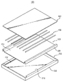
図1は本発明の一実施形態によるバックライトアセンブリを示す分解斜視図であり、図2は図1に示されたバックライトアセンブリの結合された断面を示す断面図である。
図1及び図2に示すように、本発明の一実施形態によるバックライトアセンブリ100は、収納容器200、反射部材300、光源400及び拡散板500を含む。
収納容器200は底部210及び底部210の端部位から延長され収納空間を形成する側部220で構成される。光源400の長さ方向と平行な側部220は底部210から上部方向に垂直に延長された後、収納容器200の内側方向に屈曲され、溝230を形成する。収納容器200は、一例で、強度が優れ、変形が少ない金属からなる。
Hereinafter, a preferred embodiment of the present invention will be described in more detail with reference to the drawings.
FIG. 1 is an exploded perspective view illustrating a backlight assembly according to an exemplary embodiment of the present invention, and FIG. 2 is a cross-sectional view illustrating a combined cross section of the backlight assembly illustrated in FIG.
As shown in FIGS. 1 and 2, the
The
反射部材300は光源400の下部及び側部に配置され光源400から発生された光を反射させる。反射部材300は、一例で、白色のポリエチレン・テレフタレートPET材質からなる。反射部材300は、収納容器200の底部210に密着される反射部310及び反射部310から延長され収納容器200の溝に挿入される固定部320を含む。固定部320は、反射部310から上部方向に延長された後、溝230に挿入されることができるように2度にかけて屈曲され、“U”字形状を有するようになる。このような固定部320は反射部310の両側に対称的に形成される。反射部材300は所定厚さを有する樹脂物質からなり、固定部320の屈曲に対応して元の状態に復元しようとする弾性力を有する。従って、反射部310の両側に形成された固定部320をそれぞれ収納容器200の両側部220に形成された溝320に挿入すると、前記した弾性力により反射部材300は収納容器200の内部に安定的に配置される。
The
光源400は反射部材300の上部に配置され、外部のインバーター(図示せず)から印加される電源に反応して光を発生する。本実施形態において、光源400は複数のランプ400からなる。ランプ400は、一例で、細くて長い円筒形状の冷陰極線管ランプCCFLからなる。ランプ400はバックライトアセンブリ100の輝度均一性のために等間隔に配置されることが望ましく、ランプ400の個数は要求される輝度特性によって変更できる。
一方、ランプ400は“U”字形態に撓まれた形状を有することができる。これとは異なり、光源400は複数の発光ダイオードLEDからなることができる。
拡散板500はランプ400の上部に配置され、ランプ400から出射される光を拡散させ輝度均一性を向上させる。拡散板500は所定の厚さを有する四角プレート形状を有し、ランプ400と一定間隔に離隔されるように配置される。拡散板500は、一例で、ポリメチル・メタクリレート(poly methyl Methacrylate:PMMA)材質からなり、内部に光の拡散のための拡散剤を含む。拡散板500の端部位の中でランプ400の長さ方向に並んでいる端部位は収納容器200の側部220によって支持される。
The
Meanwhile, the
The
図3は図1に収納容器を具体的に示す斜視図である。図1及び図3に示すように、収納容器200は底部210及び底部210の端部位から延長された側部220を含む。
側部220はランプ400の長さ方向と並んでいる第1及び第2側部240、250と、ランプ400の長さ方向と垂直な第3及び第4側部260、270と、で区分される。第1側部240と第2側部250は互いに対称的な構造を有し、第3側部260と第4側部270は互いに対称的な構造を有する。
第1側部240は、底部210から上部方向に垂直に延長された側壁242、及び側壁242から収納容器200の内側方向に延長された支持部244で構成される。支持部244は底部210と平行に配置される。従って、底部210、側壁242及び支持部244の間には反射部材320の固定部320を固定するための溝230が形成される。支持部244の延長長さは固定部320を安定的に固定することさえできれば、収納容器200の外郭サイズを減少させるために小さいほど望ましい。一例で、支持部244の延長長さは約5mm以下に形成される。
FIG. 3 is a perspective view specifically showing the storage container in FIG. As shown in FIGS. 1 and 3, the
The
The
第2側部250は、第1側部240と互いに対称的な構造を有するので、その重複される説明は省略することにする。
図4は図1に示された反射部材を具体的に示す斜視図であり、図5は図4のI−I’線に沿って切断した断面図である。
図3、図4及び図5に示すように、反射部材300は、収納容器200の底部210に密着される反射部310、及び反射部310から延長され側部220の溝230に固定される固定部320を含む。固定部320は反射部310の両側に対称的に形成される。
Since the
4 is a perspective view specifically showing the reflecting member shown in FIG. 1, and FIG. 5 is a cross-sectional view taken along the line II ′ of FIG.
As shown in FIGS. 3, 4, and 5, the reflecting
固定部320は、反射部310から収納容器200の支持部244方向に延長される第1固定面322、第1固定面322から延長され支持部244に密着される第2固定面324、及び第2固定面324から収納容器200の底部210まで延長され、収納容器200の側壁242に密着される第3固定面326を含む。このとき、第1固定面322は反射部310と成す内角が鈍角になるように斜めの方向に形成される。
反射部材300は、反射部310と第1固定面322とが接する境界に形成された第1グルーブ332、第1固定面322と第2固定面324とが接する境界に形成される第2グルーブ334、及び第2固定面324と第3固定面326とが接する境界に形成された第3グルーブ336を有する。第1グルーブ332、第2グルーブ334及び第3グルーブ336は、各固定面が容易に屈曲されるようにする役割を遂行する。
図6は本発明の他の実施形態によるバックライトアセンブリを示す分解斜視図であり、図7は図6に示されたバックライトアセンブリの結合された断面を示す断面図である。
The fixing
The
FIG. 6 is an exploded perspective view illustrating a backlight assembly according to another embodiment of the present invention, and FIG. 7 is a cross-sectional view illustrating a combined cross section of the backlight assembly illustrated in FIG.
図6及び図7に示すように、本発明の他の実施形態によるバックライトアセンブリ600は、収納容器200、反射部材300、ランプ400及び拡散板500を含む。また、バックライトアセンブリ600は、ランプ400を固定するためのランプ固定部材610及びランプ400の末端部に配置されるサイドモールド620をさらに含む。
収納容器200は底部210に結合孔212が形成されたことを除いては図1に示されたのと同一の構造を有するので、同一の参照番号を使用し、その重複される詳細な説明は省略する。収納容器200の底部210にはランプ固定部材610との結合のための結合孔212が形成される。結合孔212は円形態の開口からなり、ランプ固定部材610の結合部616に対応して形成される。
As shown in FIGS. 6 and 7, the
Since the receiving
反射部材300は反射部310に貫通孔312が形成されていることを除いては図1に示されたのと同一の構造を有するので、同一の参照番号を使用し、その重複される詳細な説明は省略する。反射部材300の反射部310にはランプ固定部材610と収納容器200との結合のための貫通孔312が形成される。貫通孔312は結合孔212より大きい直径を有する円形態の開口からなり、ランプ固定部材610の結合部616に対応して形成される。
ランプ400は反射部材300の上部に互いに平行に配置される。ランプ400は一字形状を有するか、“U”字形態に撓まれた形状を有することができる。ランプ400はバックライトアセンブリ600の輝度均一性のために等間隔に配置されることが望ましく、ランプ400の個数は要求される輝度特性によって変更できる。一方、バックライトアセンブリ600はランプ400を固定するためのランプホルダー410をさらに含むことができる。ランプ400の末端部はランプホルダー410に挿入されて固定され、ランプホルダー410は収納容器200に結合され固定される。一例で、一つのランプホルダー410には互いに隣接する2つのランプ400が結合される。
The
The
拡散板500は、ランプ400の上部に配置され、ランプ400から出射される光を拡散させ輝度均一性を向上させる。拡散板500は収納容器200及びサイドモールド620によって支持される。即ち、拡散板500の端部位のうちランプ400の長さ方向に並んでいる端部位は収納容器200の側部220によって支持され、ランプ400の長さ方向に垂直な端部位はサイドモールド620によって支持される。一方、拡散板500にはサイドモールド620との結合位置をガイドするためのガイド溝510が形成されることができる。
ランプ固定部材610は収納容器200の底部210に結合されランプ400を固定する。固定部材610は少なくとも一つのランプ固定部612、拡散板支持部614及び結合部616を含む。ランプ固定部612はランプ400の挿入のための一部が開口され、挿入されたランプ400を固定する。拡散板支持部614はランプ固定部612よりさらに高い高さに突出され拡散板500を支持する。結合部616はランプ固定部材610を底部210に固定する。結合部616は反射部材300の貫通孔312及び収納容器200の結合孔212を貫通した後、収納容器200の背面に固定される。ランプ固定部材610と収納容器200との結合によって、反射部材300がランプ400の長さ方向に沿って移動することが防止される。
The
The
本実施形態において、ランプ固定部材610は2つのランプ固定部612を有する。2つのランプ固定部612は中央に位置した拡散板支持部614を基準にして両側にそれぞれ一つずつ配置される。これとは異なり、ランプ固定部材610は2つ以上のランプ固定部612を有することができる。例えば、ランプ固定部612が4つの場合、拡散板支持部614を基準にして両側に2つずつのランプ固定部612が配置される。
ランプ固定部材610はランプ400の長さ方向に垂直な方向に沿ってジグザグ形態に配置される。ランプ固定部材610が一直線上に配置される場合、ランプ固定部材610が位置した領域のみ暗く見える暗線などの品質不良が発生し得る。ランプ固定部材610が一直線上に配置されないようにジグザグ形態に配置されることが望ましい。
In the present embodiment, the
The
サイドモールド620はランプ400の末端部に対応されて配置され、拡散板500を支持する。サイドモールド620はランプホルダー410が外部に露出されないようにカバーしながらランプホルダー410を固定する。サイドモールド620は、他の領域に比べて輝度が相対的に低いランプ400の両側末端領域、即ち、ランプ400の電極が形成された領域を遮蔽し輝度不均一を除去する。また、サイドモールド620は上部に配置される拡散板500を支持しながら拡散板500の収納位置をガイドする。サイドモールド620は、拡散板500の収納位置をガイドするために突出部622を有する。拡散板500のガイド溝510と突出部622との結合によって拡散板500は安定的に固定される。
バックライトアセンブリ600は拡散板500の上部に配置される光学シート630、拡散板500及び光学シート630の端部位を固定するミドルモールド640、及びランプ400の発光のための電源を供給するインバーター650をさらに含む。
The
The
光学シート630は拡散板500を経て出射される光の経路を変更させ、光学特性を向上させる。光学シート630は拡散板500を通じて拡散された光を正面方向に集光させ正面輝度を向上させる集光シートを含むことができる。また、光学シート630は拡散板500を通じて拡散された光を再度拡散させ輝度均一性を向上させる拡散シートを含むことができる。一方、バックライトアセンブリ600の要求される輝度特性によって多様な種類の光学シートを追加したり除去したりすることが可能である。
ミドルモールド640は収納容器200と結合され拡散板500と光学シート630を固定する。ミドルモールド640は拡散板500及び光学シート630の上部面の端部位を固定し、収納容器200の側部220と結合される。ミドルモールド640は大きさが大きいほど一つの一体型に製作することが難しくなるので、2つまたは4つの切片に分割して形成することができる。
The
The
インバーター550は、収納容器200の背面に配置され、ランプ400を駆動するための電源を供給する。インバーター650は外部から入力される低電位の交流電源をランプ400の駆動に適合した高電位の交流電源に昇圧させて出力する。インバーター650から供給された電源はランプワイヤー652を通じてそれぞれのランプ400に印加される。
図8は本発明の一実施形態による液晶表示装置を示す分解斜視図であり、図9は図8に示された液晶表示装置の結合された断面を示す断面図である。
図8及び図9に示すように、本発明の一実施形態による液晶表示装置700は、バックライトアセンブリ600、表示ユニット800及びトップシャーシ900を含む。
The inverter 550 is disposed on the back surface of the
FIG. 8 is an exploded perspective view showing a liquid crystal display device according to an embodiment of the present invention, and FIG. 9 is a cross-sectional view showing a combined cross section of the liquid crystal display device shown in FIG.
As shown in FIGS. 8 and 9, a liquid
バックライトアセンブリ600は、図6に示されたのと同一の構造を有するので、同一の参照番号を使用し、その重複される詳細な説明は省略する。一方、バックライトアセンブリ600は図1に示されたのと同一の構造を有することができる。
表示ユニット800は、バックライトアセンブリ600から供給される光を用いて画像を表示する液晶表示パネル810、及び液晶表示パネル810を駆動するための駆動回路部820を含む。
液晶表示パネル810は、薄膜トランジスタ(以下、TFTと称する)基板812、TFT基板812と対向して結合されるカラーフィルター基板814、及び前記2つの基板812、814の間に介在された液晶816を含む。
Since the
The
The liquid
TFT基板812は、スイッチング素子TFT(図示せず)がマトリックス状に形成された透明なガラス基板である。前記TFTのソース及びゲート端子にはそれぞれデータ及びゲートラインが連結され、ドレイン端子には透明な導電性材質からなる画素電極(図示せず)が連結される。
カラーフィルター基板814は、色画素であるR、G、B画素(図示せず)が薄膜工程によって形成された基板である。カラーフィルター基板814には透明な導電性材質からなる共通電極(図示せず)が形成される。
このような構成を有する液晶表示パネル810は、前記TFT端子に電源が印加されTFTがターンオンされると、画素電極と共通電極との間には電界が形成される。このような電界によってTFT基板812とカラーフィルター基板814との間に介在された液晶816の配列が変化され、液晶816の配列変化によってバックライトアセンブリ600から供給される光の透過度が変更され所望する階調の画像を表示するようになる。
The
The
In the liquid
駆動回路部820は、液晶表示パネル810にデータ駆動信号を供給するデータ印刷回路基板822、液晶表示パネル810にゲート駆動信号を供給するゲート印刷回路基板824、データ印刷回路基板822を液晶表示パネル810に連結するデータ可撓性回路フィルム826、及びゲート印刷回路基板824を液晶表示パネル810に連結するゲート可撓性回路フィルム828を含む。データ可撓性回路フィルム826及びゲート可撓性回路フィルム828は、例えば、テープキャリアパッケージTCPまたはチップオンフィルムCOFからなる。
データ印刷回路基板822はデータ可撓性回路フィルム826の折曲によって収納容器200の側面または背面に配置され、ゲート印刷回路基板824はゲート可撓性回路フィルム828の折曲によって収納容器200の側面または背面に配置される。一方、ゲート印刷回路基板824は液晶表示パネル810及びゲート可撓性回路フィルム828に別途の信号配線を形成することによって、除去されることができる。
トップシャーシ900は液晶表示パネル810の端部位を取り囲み収納容器200に結合されて液晶表示パネル810をバックライトアセンブリ600の上部に固定する。トップシャーシ900は外部衝撃による液晶表示パネル810の破損を防止し、液晶表示パネル810がバックライトアセンブリ600から離脱されることを防止する。トップシャーシ900は、一例で、変形が少なく強度が優れた金属からなる。
The driving
The data printed
The
このようなバックライトアセンブリ及びこれを有する液晶表示装置によると、反射部材を収納容器に固定するために両面テープを付着する工程を除去し反射部材の組立工程を単純化させることができ、反射部材の平坦度を向上させることができる。
また、収納容器の側部のサイズが減少されバックライトアセンブリの外郭サイズを減少させることができる。
以上、本発明の実施形態によって詳細に説明したが、本発明はこれに限定されず、本発明が属する技術分野において通常の知識を有する者であれば、本発明の思想と精神を離れることなく、本発明を修正または変更できる。
According to the backlight assembly and the liquid crystal display device having the backlight assembly, the process of attaching the double-sided tape to fix the reflective member to the storage container can be removed, and the assembly process of the reflective member can be simplified. The flatness of can be improved.
In addition, the size of the side portion of the storage container is reduced, and the outer size of the backlight assembly can be reduced.
As described above, the embodiments of the present invention have been described in detail. However, the present invention is not limited thereto, and those who have ordinary knowledge in the technical field to which the present invention belongs can be used without departing from the spirit and spirit of the present invention. The present invention can be modified or changed.
100 バックライトアセンブリ
200 収納容器
210 底部
220 側部
230 溝
300 反射部材
310 反射部
320 固定部
400 ランプ
500 拡散板
610 ランプ固定部材
612 ランプ固定部
614 拡散板支持部
616 結合部
620 サイドモールド
630 光学シート
640 ミドルモールド
650 インバーター
700 液晶表示装置
800 表示ユニット
810 液晶表示パネル
820 駆動回路部
900 トップシャーシ
100
Claims (35)
前記底部に密着され反射部及び前記反射部から延長され前記溝に挿入される固定部を含む反射部材と、
前記反射部材上部に配置される光源と、
を含み、
前記側部は、
前記底部から垂直に延長された側壁と、
前記側壁から前記収納容器の内側に延長され前記溝を形成する支持部と、
を含み、
前記側壁は、第1側壁、第2側壁、第3側壁、及び第4側壁を含み、前記第1側壁、第2側壁、第3側壁、及び第4側壁のうち、二つの側壁は前記支持部と接触し、
前記固定部は、
前記反射部から上方に延長される第1固定面と、
前記第1固定面から外部に延長され前記支持部に密着される第2固定面と、
前記第2固定面から下方に延長され、前記側壁と密着される第3固定面と、
を含み、
前記反射部材には前記反射部と前記第1固定面とが接する境界に第1グルーブが形成されることを特徴とするバックライトアセンブリ。 A storage container including a bottom part and a side part extending from the bottom part to form a groove;
A reflective member that includes a fixed portion that is in close contact with the bottom and extends from the reflective portion and is inserted into the groove;
A light source disposed on the reflecting member;
Only including,
The side is
Side walls extending vertically from the bottom;
A support part extending from the side wall to the inside of the storage container to form the groove;
Including
The sidewall includes a first sidewall, a second sidewall, a third sidewall, and a fourth sidewall, and two of the first sidewall, the second sidewall, the third sidewall, and the fourth sidewall are the support portion. In contact with
The fixing part is
A first fixed surface extending upward from the reflective portion;
A second fixed surface that extends outward from the first fixed surface and is in close contact with the support;
A third fixed surface that extends downward from the second fixed surface and is in close contact with the side wall;
Including
The backlight assembly according to claim 1, wherein a first groove is formed at a boundary where the reflection portion and the first fixed surface are in contact with each other .
貫通孔が形成され、前記底部に密着される反射部及び前記反射部から延長され前記溝に挿入される固定部を含む反射部材と、
前記反射部材上部に配置され、少なくとも一つのランプを有する光源と、
前記ランプを前記底部に結合させる光源固定部と、
前記光源の上部に配置され前記光源からの光を拡散させる拡散板と、
を含み、
前記側部は、
前記底部から垂直に延長された側壁と、
前記側壁から前記収納容器の内側に延長され、前記溝を形成する支持部と、
を含み、
前記側壁は、第1側壁、第2側壁、第3側壁、及び第4側壁を含み、
前記固定部は、
前記反射部から上方に延長される第1固定面と、
前記第1固定面から外部に延長され、前記支持部に密着される第2固定面と、
前記第2固定面から下方に延長され、前記側壁と密着される第3固定面と、
を含み、
前記第1固定面と前記反射部との角は鈍角であり、
前記反射部材には前記反射部と前記第1固定面とが接する境界に第1グルーブが形成されることを特徴とするバックライトアセンブリ。 A storage container including a bottom portion in which a coupling hole is formed and a side portion extending from the bottom portion to form a groove;
A reflection member including a reflection part formed with a through-hole and closely attached to the bottom part, and a fixing part extending from the reflection part and inserted into the groove;
A light source disposed on the reflective member and having at least one lamp;
A light source fixing part for coupling the lamp to the bottom part;
A diffusion plate disposed on the light source and diffusing light from the light source;
Only including,
The side is
Side walls extending vertically from the bottom;
A support portion extending from the side wall to the inside of the storage container and forming the groove;
Including
The side walls include a first side wall, a second side wall, a third side wall, and a fourth side wall,
The fixing part is
A first fixed surface extending upward from the reflective portion;
A second fixed surface extending outward from the first fixed surface and being in close contact with the support portion;
A third fixed surface that extends downward from the second fixed surface and is in close contact with the side wall;
Including
An angle between the first fixed surface and the reflecting portion is an obtuse angle,
The backlight assembly according to claim 1, wherein a first groove is formed at a boundary where the reflection portion and the first fixed surface are in contact with each other.
前記ランプが挿入され、開口された円の形状を有するランプ固定部と、
前記拡散板を支持する拡散板支持部と、
前記貫通孔及び前記結合孔を通じて前記底部と結合される結合部と、を含むことを特徴とする請求項11又は請求項12記載のバックライトアセンブリ。 The lamp fixing member is
A lamp fixing part having a circular shape in which the lamp is inserted and opened;
A diffusion plate support for supporting the diffusion plate;
The backlight assembly according to claim 11 , further comprising a coupling portion coupled to the bottom through the through hole and the coupling hole.
前記拡散板及び前記光学シートの端部位を固定するミドルモールドと、
前記光源の発光のための電源を供給するインバーターと、
をさらに含むことを特徴とする請求項21記載のバックライトアセンブリ。 An optical sheet disposed on top of the diffuser;
A middle mold for fixing the end portions of the diffusion plate and the optical sheet;
An inverter for supplying power for light emission of the light source;
The backlight assembly of claim 21 , further comprising:
前記バックライトアセンブリから供給される光を用いて画像を表示する液晶表示パネルとを含み、
前記側部は、
前記底部から垂直に延長された側壁と、
前記側壁から前記収納容器の内側に延長され前記溝を形成する支持部と、
を含み、
前記側壁は、第1側壁、第2側壁、第3側壁、及び第4側壁を含み、前記第1側壁、第2側壁、第3側壁、及び第4側壁のうち、二つの側壁は前記支持部と接触し、
前記固定部は、
前記反射部から上方に延長される第1固定面と、
前記第1固定面から外部に延長され前記支持部に密着される第2固定面と、
前記第2固定面から下方に延長され、前記側壁と密着される第3固定面と、
を含み、
前記反射部材には、前記反射部と前記第1固定面とが接する境界に第1グルーブが形成されることを特徴とする液晶表示装置。 A storage container including a bottom portion in which a coupling hole is formed and a side portion extending from the bottom portion to form a groove, and a reflective portion in which a through hole is formed and closely contacting the bottom portion and extending from the reflective portion and inserted into the groove A backlight member including a reflection member including a fixed portion and a light source disposed on the reflection member;
A liquid crystal display panel for displaying an image using light supplied from the backlight assembly ,
The side is
Side walls extending vertically from the bottom;
A support part extending from the side wall to the inside of the storage container to form the groove;
Including
The sidewall includes a first sidewall, a second sidewall, a third sidewall, and a fourth sidewall, and two of the first sidewall, the second sidewall, the third sidewall, and the fourth sidewall are the support portion. In contact with
The fixing part is
A first fixed surface extending upward from the reflective portion;
A second fixed surface that extends outward from the first fixed surface and is in close contact with the support;
A third fixed surface that extends downward from the second fixed surface and is in close contact with the side wall;
Including
The liquid crystal display device according to claim 1, wherein a first groove is formed at a boundary where the reflection portion and the first fixed surface are in contact with the reflection member .
前記ランプが挿入され、開口された円の形状を有するランプ固定部と、
前記拡散板を支持する拡散板支持部と、
前記貫通孔及び前記結合孔を通じて前記底部と結合される結合部と、
を含むことを特徴とする請求項30記載の液晶表示装置。 The lamp fixing member is
A lamp fixing part having a circular shape in which the lamp is inserted and opened;
A diffusion plate support for supporting the diffusion plate;
A coupling portion coupled to the bottom through the through hole and the coupling hole;
The liquid crystal display device according to claim 30 , comprising:
前記サイドモールドは、前記拡散板の実装位置をガイドするための突出部を含み、前記拡散板は、前記突出部に対応するガイド溝を含むことを特徴とする請求項33記載の液晶表示装置。 A side mold disposed to correspond to the end of the lamp and supporting the diffusion plate;
The liquid crystal display device according to claim 33 , wherein the side mold includes a protrusion for guiding a mounting position of the diffusion plate, and the diffusion plate includes a guide groove corresponding to the protrusion.
前記拡散板及び前記光学シートの縁部を固定するミドルモールドと、
前記光源の発光のための電源を供給するインバーターと、
をさらに含むことを特徴とする請求項34記載のバックライトアセンブリ。
An optical sheet disposed on top of the diffuser;
A middle mold for fixing edges of the diffusion plate and the optical sheet;
An inverter for supplying power for light emission of the light source;
The backlight assembly of claim 34 , further comprising:
Applications Claiming Priority (2)
| Application Number | Priority Date | Filing Date | Title |
|---|---|---|---|
| KR2004-097057 | 2004-11-24 | ||
| KR1020040097057A KR101035848B1 (en) | 2004-11-24 | 2004-11-24 | Back light assembly and liquid crystal display device having the same |
Publications (3)
| Publication Number | Publication Date |
|---|---|
| JP2006146126A JP2006146126A (en) | 2006-06-08 |
| JP2006146126A5 JP2006146126A5 (en) | 2008-02-07 |
| JP4758661B2 true JP4758661B2 (en) | 2011-08-31 |
Family
ID=36460735
Family Applications (1)
| Application Number | Title | Priority Date | Filing Date |
|---|---|---|---|
| JP2005058356A Expired - Fee Related JP4758661B2 (en) | 2004-11-24 | 2005-03-03 | Backlight assembly and liquid crystal display device having the same |
Country Status (5)
| Country | Link |
|---|---|
| US (1) | US7220045B2 (en) |
| JP (1) | JP4758661B2 (en) |
| KR (1) | KR101035848B1 (en) |
| CN (1) | CN100462801C (en) |
| TW (1) | TWI443421B (en) |
Families Citing this family (34)
| Publication number | Priority date | Publication date | Assignee | Title |
|---|---|---|---|---|
| JP3496589B2 (en) * | 1999-09-21 | 2004-02-16 | 日本電気株式会社 | Information processing equipment |
| KR20070001362A (en) * | 2005-06-29 | 2007-01-04 | 삼성전자주식회사 | Liquid crystal display |
| KR20070002756A (en) * | 2005-06-30 | 2007-01-05 | 엘지.필립스 엘시디 주식회사 | Backlight unit |
| US20080037287A1 (en) * | 2006-08-14 | 2008-02-14 | Robert Michael Krohn | Backlight panel and manufacturing method thereof |
| CN100445840C (en) * | 2005-11-26 | 2008-12-24 | 鸿富锦精密工业(深圳)有限公司 | Structure of lamp box and backlight module |
| TW200734758A (en) * | 2006-03-08 | 2007-09-16 | Chi Mei Optoelectronics Corp | Direct type backlight module and application thereof |
| KR101299129B1 (en) * | 2006-03-16 | 2013-08-21 | 엘지디스플레이 주식회사 | Liquid crystal display device module |
| CN100561313C (en) * | 2006-07-05 | 2009-11-18 | 鸿富锦精密工业(深圳)有限公司 | Module backlight and lamp tube securing holder thereof |
| KR101385231B1 (en) * | 2006-08-24 | 2014-04-14 | 삼성디스플레이 주식회사 | Flat panel display |
| JP4899846B2 (en) * | 2006-12-08 | 2012-03-21 | パナソニック株式会社 | Backlight unit and liquid crystal display device |
| WO2008085161A1 (en) * | 2007-01-09 | 2008-07-17 | Lighting Panels, Llc | Backlight panel and manufacturing method thereof |
| WO2008129724A1 (en) * | 2007-04-09 | 2008-10-30 | Sharp Kabushiki Kaisha | Illuminating apparatus for display apparatus, display apparatus and television receiving apparatus |
| EP2151709B1 (en) * | 2007-05-31 | 2012-03-14 | Sharp Kabushiki Kaisha | Display device and tv receiver |
| US7859831B2 (en) * | 2007-06-27 | 2010-12-28 | Epson Imaging Devices Corporation | Electro-optical device and electronic apparatus |
| JP4469922B2 (en) * | 2007-07-04 | 2010-06-02 | シャープ株式会社 | Lighting device, display device, television receiver |
| KR101385205B1 (en) * | 2007-07-25 | 2014-04-14 | 삼성디스플레이 주식회사 | A liquid crystal display with a backlight assembly having an improved structure |
| KR101448893B1 (en) * | 2007-12-20 | 2014-10-13 | 삼성디스플레이 주식회사 | Liquid crystal display module having direct contact between top chassis and bottom chasiss and manufacturing method thereof |
| WO2009093390A1 (en) * | 2008-01-22 | 2009-07-30 | Sharp Kabushiki Kaisha | Lamp holder, member to which subject is to be attached, illuminating device, display device and television receiving device |
| CN101952649A (en) * | 2008-02-27 | 2011-01-19 | 夏普株式会社 | Lighting apparatus, display apparatus and television receiving apparatus |
| TWI524311B (en) * | 2008-11-06 | 2016-03-01 | 國立台灣大學 | Educational kit for a display device and educational method of utilizing the same |
| AU2010296605A1 (en) * | 2009-09-16 | 2012-04-05 | Sharp Kabushiki Kaisha | Lighting device, display apparatus, and television receiver |
| EP2479479B1 (en) | 2009-09-16 | 2014-07-30 | Sharp Kabushiki Kaisha | Lighting device, display device, and television receiver |
| WO2011033900A1 (en) | 2009-09-16 | 2011-03-24 | シャープ株式会社 | Illumination device, display device and television reception device |
| SG179166A1 (en) | 2009-09-16 | 2012-05-30 | Sharp Kk | Lighting device, display apparatus, and television receiver |
| WO2011033896A1 (en) | 2009-09-16 | 2011-03-24 | シャープ株式会社 | Lighting device, display apparatus, and television receiver |
| WO2011036954A1 (en) | 2009-09-28 | 2011-03-31 | シャープ株式会社 | Illuminating device, display device and television receiver |
| WO2011062023A1 (en) | 2009-11-19 | 2011-05-26 | シャープ株式会社 | Lighting device, display device, and television receiving device |
| WO2011074334A1 (en) | 2009-12-15 | 2011-06-23 | シャープ株式会社 | Illumination device, display device, and television receiver |
| US8568012B2 (en) * | 2010-01-18 | 2013-10-29 | Lg Innotek Co., Ltd. | Lighting unit and display device having the same |
| CN202228998U (en) * | 2011-08-10 | 2012-05-23 | 深圳市华星光电技术有限公司 | Backlight module and liquid crystal display device applying same |
| KR20130051133A (en) * | 2011-11-09 | 2013-05-20 | 삼성전자주식회사 | Liquid crystal panel assembly and liquid crystal display apparatus |
| CN103292267B (en) * | 2013-04-25 | 2015-11-25 | 深圳市华星光电技术有限公司 | Large scale back light module backboard splicing construction and liquid crystal indicator |
| JP6007330B2 (en) * | 2013-07-19 | 2016-10-12 | 堺ディスプレイプロダクト株式会社 | Display device |
| KR20160006285A (en) * | 2014-07-08 | 2016-01-19 | 삼성디스플레이 주식회사 | Display device |
Family Cites Families (13)
| Publication number | Priority date | Publication date | Assignee | Title |
|---|---|---|---|---|
| EP0148286B1 (en) * | 1983-12-30 | 1987-11-19 | Siegfried Geldner | Flanged joint |
| TW569059B (en) * | 1999-12-09 | 2004-01-01 | Samsung Electronics Co Ltd | Liquid crystal display device |
| JP3847532B2 (en) * | 2000-07-05 | 2006-11-22 | 株式会社日立製作所 | Liquid crystal module and liquid crystal monitor equipped with this liquid crystal module |
| KR100640987B1 (en) * | 2000-10-14 | 2006-11-02 | 엘지.필립스 엘시디 주식회사 | backlight assembly of liquid crystal display module |
| JP2002182209A (en) * | 2000-12-19 | 2002-06-26 | Advanced Display Inc | Liquid crystal display device |
| JP3728723B2 (en) * | 2000-12-20 | 2005-12-21 | ミネベア株式会社 | Surface lighting device |
| JP2002311428A (en) * | 2001-04-11 | 2002-10-23 | Hitachi Ltd | Liquid crystal display |
| JP2002311417A (en) * | 2001-04-17 | 2002-10-23 | Nec Corp | Liquid crystal display device |
| KR100840726B1 (en) * | 2002-05-29 | 2008-06-23 | 삼성전자주식회사 | Back light assembly and liquid crystal display having the same |
| KR100545101B1 (en) * | 2002-08-29 | 2006-01-24 | 주식회사 우영 | Back light unit |
| KR100913307B1 (en) * | 2002-12-12 | 2009-08-26 | 삼성전자주식회사 | Backlight assembly and liquid crystal display device having the same |
| TW576511U (en) * | 2003-03-21 | 2004-02-11 | Hon Hai Prec Ind Co Ltd | Backlight module and the housing thereof |
| JP2004325658A (en) * | 2003-04-23 | 2004-11-18 | Fuji Photo Optical Co Ltd | Liquid crystal display device |
-
2004
- 2004-11-24 KR KR1020040097057A patent/KR101035848B1/en not_active IP Right Cessation
-
2005
- 2005-03-03 JP JP2005058356A patent/JP4758661B2/en not_active Expired - Fee Related
- 2005-06-30 TW TW094122091A patent/TWI443421B/en not_active IP Right Cessation
- 2005-08-12 CN CNB2005100903555A patent/CN100462801C/en not_active Expired - Fee Related
- 2005-09-19 US US11/230,123 patent/US7220045B2/en active Active
Also Published As
| Publication number | Publication date |
|---|---|
| US20060109643A1 (en) | 2006-05-25 |
| JP2006146126A (en) | 2006-06-08 |
| TW200617521A (en) | 2006-06-01 |
| US7220045B2 (en) | 2007-05-22 |
| CN1779524A (en) | 2006-05-31 |
| CN100462801C (en) | 2009-02-18 |
| KR20060057866A (en) | 2006-05-29 |
| KR101035848B1 (en) | 2011-05-19 |
| TWI443421B (en) | 2014-07-01 |
Similar Documents
| Publication | Publication Date | Title |
|---|---|---|
| JP4758661B2 (en) | Backlight assembly and liquid crystal display device having the same | |
| KR101245113B1 (en) | Lamp fixing member, back light assembly and liquid crystal display apparatus having the same | |
| JP2006185889A (en) | Backlight assembly and liquid crystal display device provided with the same | |
| JP4896669B2 (en) | Backlight assembly, liquid crystal display device having the same, and method of manufacturing lamp fixing member | |
| KR101041053B1 (en) | Back light assembly and liquid crystal display device having the same | |
| JP2006066359A (en) | Backlight assembly and liquid crystal display apparatus having the same | |
| KR20070023271A (en) | Display apparatus and method of manufacturing thereof | |
| JP2006216540A (en) | Backlight assembly and display device having the same | |
| KR20060131248A (en) | Backlight assembly and liquid crystal display apparatus having the same | |
| KR20060116513A (en) | Back light assembly and liquid crystal display device having the same | |
| KR101432501B1 (en) | Back light assembly and liquid crystal display device having the same | |
| KR20060098978A (en) | Back light assembly and display device having the same | |
| KR20110097086A (en) | Backlight assembly and display apparatus having the same | |
| JP2007157698A (en) | Lamp fixing member, and backlight assembly having it, and liquid crystal display device | |
| JP2006066357A (en) | Backlight assembly and liquid crystal display having above | |
| KR20080017551A (en) | Back light assembly and liquid crystal display apparatus having the same | |
| KR101284031B1 (en) | Back light assembly and liquid crystal display apparatus having the same | |
| KR20070063665A (en) | Lamp fixing member, back light assembly and liquid crystal display apparatus having the same | |
| KR20060111784A (en) | Back light assembly and liquid crystal display apparatus having the same | |
| KR20080055065A (en) | Back light assembly and display apparatus having the same | |
| KR20070080276A (en) | Back light assembly and liquid crystal display apparatus having the same | |
| KR20060075292A (en) | Back light assembly and liquid crystal display device having the same | |
| KR20060044015A (en) | Back light assembly and liquid crystal display device having the same | |
| KR20070079686A (en) | Back light assembly and liquid crystal display apparatus having the same | |
| KR20070092396A (en) | Back light assembly |
Legal Events
| Date | Code | Title | Description |
|---|---|---|---|
| A521 | Request for written amendment filed |
Free format text: JAPANESE INTERMEDIATE CODE: A523 Effective date: 20071218 |
|
| A621 | Written request for application examination |
Free format text: JAPANESE INTERMEDIATE CODE: A621 Effective date: 20071218 |
|
| A131 | Notification of reasons for refusal |
Free format text: JAPANESE INTERMEDIATE CODE: A131 Effective date: 20101214 |
|
| A601 | Written request for extension of time |
Free format text: JAPANESE INTERMEDIATE CODE: A601 Effective date: 20110311 |
|
| A602 | Written permission of extension of time |
Free format text: JAPANESE INTERMEDIATE CODE: A602 Effective date: 20110316 |
|
| A521 | Request for written amendment filed |
Free format text: JAPANESE INTERMEDIATE CODE: A523 Effective date: 20110413 |
|
| A01 | Written decision to grant a patent or to grant a registration (utility model) |
Free format text: JAPANESE INTERMEDIATE CODE: A01 Effective date: 20110510 |
|
| A61 | First payment of annual fees (during grant procedure) |
Free format text: JAPANESE INTERMEDIATE CODE: A61 Effective date: 20110603 |
|
| R150 | Certificate of patent or registration of utility model |
Free format text: JAPANESE INTERMEDIATE CODE: R150 |
|
| FPAY | Renewal fee payment (event date is renewal date of database) |
Free format text: PAYMENT UNTIL: 20140610 Year of fee payment: 3 |
|
| FPAY | Renewal fee payment (event date is renewal date of database) |
Free format text: PAYMENT UNTIL: 20140610 Year of fee payment: 3 |
|
| S111 | Request for change of ownership or part of ownership |
Free format text: JAPANESE INTERMEDIATE CODE: R313111 |
|
| FPAY | Renewal fee payment (event date is renewal date of database) |
Free format text: PAYMENT UNTIL: 20140610 Year of fee payment: 3 |
|
| R371 | Transfer withdrawn |
Free format text: JAPANESE INTERMEDIATE CODE: R371 |
|
| S111 | Request for change of ownership or part of ownership |
Free format text: JAPANESE INTERMEDIATE CODE: R313111 |
|
| R350 | Written notification of registration of transfer |
Free format text: JAPANESE INTERMEDIATE CODE: R350 |
|
| R250 | Receipt of annual fees |
Free format text: JAPANESE INTERMEDIATE CODE: R250 |
|
| R250 | Receipt of annual fees |
Free format text: JAPANESE INTERMEDIATE CODE: R250 |
|
| LAPS | Cancellation because of no payment of annual fees |