JP4757050B2 - Inkjet recording head and inkjet recording method - Google Patents
Inkjet recording head and inkjet recording method Download PDFInfo
- Publication number
- JP4757050B2 JP4757050B2 JP2006035210A JP2006035210A JP4757050B2 JP 4757050 B2 JP4757050 B2 JP 4757050B2 JP 2006035210 A JP2006035210 A JP 2006035210A JP 2006035210 A JP2006035210 A JP 2006035210A JP 4757050 B2 JP4757050 B2 JP 4757050B2
- Authority
- JP
- Japan
- Prior art keywords
- heater
- ink
- temperature
- recording head
- foaming
- Prior art date
- Legal status (The legal status is an assumption and is not a legal conclusion. Google has not performed a legal analysis and makes no representation as to the accuracy of the status listed.)
- Expired - Fee Related
Links
Images


Description
本発明は、インク滴を吐出して記録を行うインクジェット記録ヘッドおよびインクジェット記録方法に関する。 The present invention relates to an ink jet recording head and an ink jet recording method for performing recording by discharging ink droplets.
インクジェット記録方式は、いわゆるノンインパクト記録方式の一つである。このインクジェット記録方式は、記録時に発生する騒音が無視し得る程度に小さく、高速記録が可能である。また、インクジェット記録方式は、種々の被記録材に対して記録が可能であり、いわゆる普通紙に対しても特別な処理を必要とせずにインクが定着して、しかも高精細な画像が廉価に得られる。このような利点から、インクジェット記録方式は、コンピューターの周辺機器としてのプリンタばかりでなく、複写機、ファクシミリ、ワードプロセッサ等の記録手段として近年急速に普及している。 The ink jet recording method is one of so-called non-impact recording methods. This ink-jet recording method has a noise that can be ignored during recording and can be recorded at high speed. In addition, the ink jet recording method can record on various recording materials, the ink is fixed without requiring any special processing on so-called plain paper, and a high-definition image is inexpensive. can get. Due to such advantages, the ink jet recording system has been rapidly spread in recent years as a recording means for copying machines, facsimiles, word processors and the like as well as printers as peripheral devices for computers.
一般的に利用されているインクジェット記録方式のインク吐出方法には、インク滴を吐出するために用いられる吐出エネルギ発生素子として、ヒータを用いる方法と、ピエゾ素子を用いる方法がある。いずれの方法においても電気信号によってインク滴の吐出を制御することができる。ヒータを用いるインク吐出方法の原理は、ヒータに電圧を印加することにより、ヒータ近傍のインクを瞬時に沸騰させて、沸騰時のインクの相変化により生じる急激な発泡圧によってインク滴を高速に吐出させる。一方、ピエゾ素子を用いるインク吐出方法の原理は、ピエゾ素子に電圧を印加することにより、ピエゾ素子が変位してこの変位時に発生する圧力によってインク滴を吐出させる。 Ink discharge methods of the ink jet recording method that are generally used include a method using a heater and a method using a piezo element as discharge energy generating elements used for discharging ink droplets. In either method, the ejection of ink droplets can be controlled by an electrical signal. The principle of the ink discharge method using a heater is that a voltage is applied to the heater to instantaneously boil the ink near the heater, and ink droplets are discharged at a high speed by the abrupt foaming pressure generated by the phase change of the ink at the time of boiling Let On the other hand, the principle of the ink ejection method using a piezo element is that a voltage is applied to the piezo element, whereby the piezo element is displaced and an ink droplet is ejected by the pressure generated at the time of the displacement.
ヒータを用いるインク吐出方法は、吐出エネルギ発生素子を配設するためのスペースを大きく確保する必要がなく、記録ヘッドの構造が簡素で、ノズルの集積化が容易であること等の利点がある。 The ink discharge method using a heater has advantages that it is not necessary to secure a large space for disposing the discharge energy generating elements, the structure of the recording head is simple, and the integration of nozzles is easy.
この種のインクジェット記録ヘッドは、インクを吐出するノズルが複数配列されてなるノズル列を備えている。ノズル列は、インクを吐出する開口である吐出口と、吐出口に対応して設けられたインクを吐出させるためのヒータと、ヒータによって気泡が発生する発泡室と、吐出口および発泡室にインクを供給する供給路とを有している。また、このインクジェット記録ヘッドは、各ノズルの供給路の発泡室側とは反対側の端部に連通され、ノズル列に沿って延在する貫通口を有する共通液室を備えている。 This type of ink jet recording head includes a nozzle array in which a plurality of nozzles that eject ink are arranged. The nozzle array includes an ejection port which is an opening for ejecting ink, a heater for ejecting ink corresponding to the ejection port, a foaming chamber in which bubbles are generated by the heater, and an ink in the ejection port and the foaming chamber. And a supply path for supplying the gas. In addition, the ink jet recording head includes a common liquid chamber having a through hole that communicates with an end portion of the supply path of each nozzle opposite to the foaming chamber side and extends along the nozzle row.
また、以上のように構成されたインクジェット記録ヘッドでは、供給液室に供給されたインクが、ノズル列を構成する各ノズルの供給路を通って発泡室側に供給され、発泡室内に充填される。発泡室内に充填されたインクは、ヒータによって膜沸騰されて発生する気泡によって、素子基板の主面、すなわちヒータの主面に対してほぼ直交する方向に飛翔されて、吐出口からインク滴として吐出される。 Further, in the ink jet recording head configured as described above, the ink supplied to the supply liquid chamber is supplied to the foaming chamber side through the supply path of each nozzle constituting the nozzle row and filled into the foaming chamber. . The ink filled in the foam chamber is ejected as ink droplets from the ejection port by air bubbles generated by boiling the film by the heater and flying in a direction substantially perpendicular to the main surface of the element substrate, that is, the main surface of the heater. Is done.
吐出口から吐出されて飛翔するインク滴は、素子基板の主面(ヒータの主面)に対してほぼ垂直方向に飛翔し、テールと呼ばれるインクの尾引きを形成する。そして、時間経過とともにそのテールがサテライトと呼ばれる複数のインク小滴に分裂して、先頭の主滴に続いて飛翔する。 The ink droplets ejected and ejected from the ejection ports fly in a direction substantially perpendicular to the main surface of the element substrate (main surface of the heater), and form an ink tail called a tail. Then, with the passage of time, the tail splits into a plurality of ink droplets called satellites, and then flies following the leading main droplet.
このため、被記録材に対して往復走査する記録ヘッドでは、インクの主滴が先に被記録材に付着して記録ドットを形成した後、サテライトが被記録材上の記録ドットから外れた位置に付着してインクの散りが形成される不都合があった。 For this reason, in a recording head that reciprocally scans the recording material, after the main droplet of ink first adheres to the recording material to form a recording dot, the satellite deviates from the recording dot on the recording material. There was a disadvantage that ink splatter was formed due to adhesion.
このようなインクの散りを防止するために、従来のインクジェット記録ヘッドとしては、記録ヘッドの走査方向と直交する吐出口の中心線の両側に、第1加熱部と第2加熱部が設けられる構成が開示されている(例えば特許文献1参照。)。このインクジェット記録ヘッドでは、往復走査するときに、第1または第2加熱部のうち、反走査方向側の加熱部を加熱することで、吐出口の中心線の反走査方向側から走査方向側に向けてインク滴を飛して、インクの散りを防止している。
ところで、従来のインクジェット記録ヘッドにおいて、図7(a)〜(c)に示すように、発泡室113内に配置されたヒータ112が加熱され、吐出口111から吐出されるインク滴のテールの状態について説明する。
By the way, in the conventional ink jet recording head, as shown in FIGS. 7A to 7C, the
インクジェット記録ヘッド、すなわち吐出口111が形成されたオリフィス基板や、インクが供給される貫通口が設けられた素子基板、またはインクの温度に伴って、インク滴のテールの状態が変化する。記録ヘッドまたはインクの温度が、例えば25℃程度の常温状態では、図7(b)に示すように、先頭の主滴の飛翔した軌道に沿ってテールが形成され、その後、サテライトも主滴と同じ軌道に沿って飛翔する。
The state of the ink droplet tail changes with the temperature of the ink jet recording head, that is, the orifice substrate on which the
しかしながら、例えば50℃程度に昇温した状態では、図7(c)に示すように、常温で吐出口111の中心軸線に沿って延びていたテールが、吐出口111内または発泡室113内でノズル配列方向と垂直な方向に向かって曲がってしまう。これは、記録ヘッドまたはインクが昇温した状態で、インクの粘度の低下や発泡パワーの増大に伴って、テールが、吐出口111内または発泡室113内でノズル配列方向と垂直な方向に対して非対称な速度分布を持つためである。
However, for example, in a state where the temperature is raised to about 50 ° C., as shown in FIG. 7C, the tail extending along the central axis of the
そして、吐出口111の中心軸線に対して曲げられたテールが、主滴の軌道から外れてサテライトとなるので、吐出口111近傍にインクが付着しやすくなり、その付着したインクと次イベントの吐出(次に吐出されたインクと)が干渉して乱れた吐出状態となる。その結果、サテライトが被記録材の記録面に着弾したときに、常温時と昇温時とではドット形成が異なってしまい、昇温時に画像劣化を発生させることがあった。さらに、最悪の場合には印字ヨレや不吐を引き起こすことがあった。
Since the tail bent with respect to the central axis of the
そこで、本発明は、インクまたは記録ヘッドの昇温時であっても常温時とほぼ同等のインク滴を形成するように制御し、インクの吐出動作の信頼性を向上することができるインクジェット記録ヘッドおよびインクジェット記録方法を提供することを目的とする。 Accordingly, the present invention provides an ink jet recording head that is controlled to form ink droplets that are substantially equivalent to those at room temperature even when the temperature of the ink or the recording head is elevated, and that can improve the reliability of the ink ejection operation. It is another object of the present invention to provide an ink jet recording method.
上述した目的を達成するため、本発明に係るインクジェット記録ヘッドは、インクを吐出する吐出口と、吐出口に対応して設けられインクを吐出させるためのヒータと、ヒータによって気泡が発生する発泡室と、吐出口および発泡室にインクを供給する供給路とを有するノズルが複数配列されたノズル列と、
供給路に連通され供給路にインクを供給する共通液室と、を備えるインクジェット記録ヘッドにおいて、
ヒータは、各ノズルの発泡室に配列された、吐出口に対向して位置する第1のヒータ及び他のヒータと、第1のヒータ及び他のヒータに対して共通液室側に位置する第2のヒータ及び更に他のヒータと、を含み、
ノズル内のインクまたはインクジェット記録ヘッドの温度を検出する温度検出手段と、
温度検出手段が検出した温度が常温時には第1のヒータ及び他のヒータを選択的に加熱し、温度検出手段が検出した温度が常温よりも高い昇温時には第2のヒータ及び更に他のヒータを選択的に加熱し、発泡室内での発泡位置を切り替える制御手段と、を備える。
In order to achieve the above-described object, an inkjet recording head according to the present invention includes an ejection port that ejects ink, a heater that is provided corresponding to the ejection port, and that generates bubbles by the heater. And a nozzle row in which a plurality of nozzles each having a discharge passage and a supply path for supplying ink to the foaming chamber are arranged;
In an inkjet recording head comprising: a common liquid chamber that communicates with a supply path and supplies ink to the supply path.
The heaters are arranged in the foaming chambers of the respective nozzles, the first heater and the other heaters located opposite to the discharge ports, and the first heater and the other heaters located on the common liquid chamber side. 2 heaters and other heaters ,
Temperature detecting means for detecting the temperature of the ink in the nozzle or the ink jet recording head;
When the temperature detected by the temperature detecting means is normal temperature, the first heater and other heaters are selectively heated, and when the temperature detected by the temperature detecting means is higher than the normal temperature, the second heater and other heaters are turned on. Control means for selectively heating and switching a foaming position in the foaming chamber.
上述したように、本発明によれば、記録ヘッドまたはインクの温度の常温時と昇温時のドット形成、印字ヨレ、不吐が発生することを抑制し、インク吐出動作の安定性を向上することができる。 As described above, according to the present invention, it is possible to suppress the occurrence of dot formation, printing misalignment, and non-discharge during normal temperature and elevated temperature of the recording head or ink, and improve the stability of the ink ejection operation. be able to.
以下、本発明の具体的な実施形態について図面を参照して説明する。 Hereinafter, specific embodiments of the present invention will be described with reference to the drawings.
(第1の実施形態)
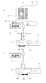
図2に第1の実施形態のインクジェット記録ヘッドを示す。図1および図2に示すように、第1の実施形態のインクジェット記録ヘッド1は、オリフィス基板6と素子基板7が接合されて構成されており、インクを吐出するノズル8が複数配列されてなるノズル列を備えている。各ノズル8は、インクを吐出する吐出口11と、この吐出口11に対応して設けられインクを吐出させるためのヒータ12と、ヒータ12によって気泡が発生する発泡室13と、吐出口11および発泡室13にインクを供給する供給路14とを有している。
(First embodiment)
FIG. 2 shows the ink jet recording head of the first embodiment. As shown in FIGS. 1 and 2, the ink jet recording head 1 of the first embodiment is configured by joining an orifice substrate 6 and an element substrate 7, and a plurality of nozzles 8 for ejecting ink are arranged. A nozzle row is provided. Each nozzle 8 includes an
また、インクジェット記録ヘッド1は、供給路14の発泡室13側と反対側の端部と連通され、ノズル列の配列方向に沿って延在する貫通口であるインク供給口15を有する共通液室16を備えている。
The ink jet recording head 1 communicates with the end of the
各ノズル8の発泡室13内には、第1および第2のヒータ12a,12bが、ノズル列の配列方向と直交する方向に沿って配列されている。第1および第2のヒータ12a,12bは、主面の面積がほぼ等しく形成されている。また、各ノズル8の吐出口11は、第1のヒータ12aに対向して配置されている。第2のヒータ12bは、第1のヒータ12aよりも共通液室16側に位置されている。
In the
そして、本実施形態のインクジェット記録ヘッド1は、インクまたは記録ヘッドの温度を検出する温度検出部21と、この温度検出部21が検出した温度に応じて、第1、第2のヒータ12a,12bのいずれかを選択的に加熱する制御部22とを備えている。
The ink jet recording head 1 according to this embodiment includes a
温度検出部21は、オリフィス基板6、素子基板7の温度、またはノズル8内を流れるインクの温度を検出する検出素子(不図示)を有している。制御部22は、CPU等を有しており、温度検出部21の検出素子に電気的に接続されている。
The
各ノズル8における第1および第2のヒータ12a,12bは、制御部22によって選択的に加熱されることで、インクまたは記録ヘッドの常温時よりも昇温時の方が、共通液室16側寄りで発泡するように構成されている。すなわち、本実施形態のインクジェット記録ヘッドの各ノズル8は、図2(b)に示すように、常温時に共通液室16と反対側の第1のヒータ12aが加熱されるように制御される。また、各ノズル8は、図2(c)に示すように、昇温時に共通液室16側の第2のヒータ12bが加熱されるように制御される。なお、図2(b),(c)において、「オン」状態にされて選択的に加熱されるヒータを黒塗りで示し、「オフ」状態にされて加熱されないヒータを白抜きで示している。
The first and
このように第1および第2のヒータ12a,12bのうちで、加熱するヒータを選択的に切り替えることで、発泡室13内における発泡位置が変更される。通常、昇温時には、図7(c)に示したように、共通液室16側へ大きくテールが曲がってしまう滴形成の挙動を、図2(c)に示すように、吐出口11の中心軸線に沿って延びる真っ直ぐなテールを形成することができる。これにより、上述したサテライトによる常温時と昇温時のドット形成差、印字ヨレ、不吐の発生が抑制される。
Thus, the foaming position in the foaming
また、第1および第2のヒータ12a,12bのうちで選択的に加熱されるヒータによる発泡に寄与する領域の総面積(有効発泡面積)が、インクまたは記録ヘッドの常温時と昇温時とで一定にされている。
Further, the total area (effective foaming area) of the region contributing to foaming by the heater selectively heated among the first and
したがって、本実施形態のインクジェット記録ヘッド1によれば、常温時と昇温時に、第1および第2のヒータ12a,12bのいずれかを選択的に加熱することで、インクまたは記録ヘッドの温度に応じて、発泡室13内での発泡位置が切り替えられる。このため、各ノズル8内のメニスカスによる速度分布が、吐出口11の中心軸線に対して対称になり、常温時と昇温時のドット形成、印字ヨレ、不吐が発生することが防止され、インク吐出動作の安定性を向上することができる。
Therefore, according to the ink jet recording head 1 of the present embodiment, the temperature of the ink or the recording head can be adjusted by selectively heating one of the first and
(第2の実施形態)
つぎに、上述した第1の実施形態では、各ノズル8の発泡室13内に2つのヒータ12a,12bが配列される構成が採られたが、発泡室内に3つのヒータが配列された第2の実施形態のインクジェット記録ヘッドについて図面を参照して説明する。
(Second Embodiment)
Next, in the first embodiment described above, the configuration in which the two
図3に、第2の実施形態のインクジェット記録ヘッドを示す。図3に示すように、第2の実施形態のインクジェット記録ヘッドでは、1つのノズル8に対応する1つの発泡室13内に、3つの第1、第2、第3のヒータ32a,32b,32cが、ノズル列の配列方向と直交する方向に沿って配列されている。
FIG. 3 shows an ink jet recording head according to the second embodiment. As shown in FIG. 3, in the ink jet recording head of the second embodiment, three first, second, and
第1、第2、第3のヒータ32a,32b,32cは、主面の面積がほぼ等しく形成されている。また、各ノズル8の吐出口11は、第1のヒータ32aと第2のヒータ32bとの境界に対向して配置されている。第3のヒータ32cは、第2のヒータ32bよりも共通液室16側に位置されている。
The first, second, and
そして、本実施形態のインクジェット記録ヘッドも、第1の実施形態と同様に、インクまたは記録ヘッドの温度を検出する温度検出部21を備えている。また、本実施形態のインクジェット記録ヘッドは、温度検出部21が検出した温度に応じて、第1、第2、第3のヒータ32a,32b,32cのいずれかを選択的に加熱する制御部22を備えている。
The ink jet recording head of the present embodiment also includes a
常温時には、共通液室16の反対側に位置する2つの第1および第2のヒータ32a,32bが加熱されて、これら第1のヒータ32aと第2のヒータ32bとに跨って気泡が発生する。また昇温時には、共通液室16側に位置する2つの第2および第3のヒータ32b,32cが加熱されて、第2のヒータ32bと第3のヒータ32cとに跨って気泡が発生する。
At normal temperature, the two first and
すなわち、配列された第1、第2、第3のヒータ32a,32b,32cは、常温時よりも昇温時の方が、共通液室16側寄りの位置で発泡する。したがって、昇温時には、共通液室16側で発泡することで、吐出口11の中心軸線に沿ってテールが形成される。
That is, the arranged first, second, and
このように、制御部22によって、各ノズル8において3つの第1、第2、第3のヒータ32a,32b,32cのうちで、加熱させるヒータを切り替えることによって、発泡室13内で気泡が生じる発泡位置が切り替えられる。これにより、通常、昇温時には、図7に示したように、共通液室側へ向かってテールが延びる方向が大きく曲がってしまう滴形成の挙動を、図3(c)に示すように、吐出口11の中心軸線に沿って真っ直ぐに延びるテールを形成することができる。これにより、上述したサテライトの常温時と昇温時のドット形成差、印字ヨレ、不吐の発生を抑制することができる。
Thus, bubbles are generated in the foaming
(他の実施形態)
続いて、上述した第2の実施形態のインクジェット記録ヘッドでは、ノズル8の吐出口11近傍部分が直線状に形成されたが、必要に応じてノズル8の形状が部分的に変更されてもよい。ノズル8の吐出口11近傍の形状が異なる第3および第4の実施形態について図面を参照して簡単に説明する。なお、便宜上、第3および第4の実施形態において、第2の実施形態と同一部材には同一符合を付して説明を省略する。
(Other embodiments)
Subsequently, in the ink jet recording head of the second embodiment described above, the vicinity of the
第3の実施形態として、図4に示すように、吐出口11から発泡室13にかけて内径が段階的に変化するように形成されたノズルにおいても、昇温時に吐出口11の中心軸線に沿ってテールが形成され、上述した作用、効果が同様に得られる。
As a third embodiment, as shown in FIG. 4, even in a nozzle formed such that the inner diameter changes stepwise from the
また、図5に示すように、第4の実施形態として、吐出口11の開口側に向かって吐出口11の内径が無段階で次第に大きくされたいわゆるテーパ形状に形成されたノズルにおいても、上述した作用、効果が同様に得られる。
Further, as shown in FIG. 5, as a fourth embodiment, the nozzle formed in a so-called tapered shape in which the inner diameter of the
また、図6に、第5の実施形態のインクジェット記録ヘッドを示す。本実施形態のインクジェット記録ヘッドでは、1つのノズル8に対応する1つの発泡室13内に、3つの第1、第2、第3、第4のヒータ42a,42b,42c,42dが、ノズル列の配列方向と直交する方向に沿って配列されている。
FIG. 6 shows an ink jet recording head of the fifth embodiment. In the ink jet recording head of the present embodiment, three first, second, third, and
第1、第2、第3のヒータ42a,42b,42c,42dは、主面の面積がほぼ等しく形成されている。また、各ノズル8の吐出口11は、第1のヒータ42aと第2のヒータ42bとの境界に対向して配置されている。第3のヒータ42cは、第2のヒータ42bよりも共通液室16側に位置され、第4のヒータ42dはさらに共通液室16側に位置されている。
The first, second, and
そして、本実施形態のインクジェット記録ヘッドも、第1の実施形態と同様に、インクまたは記録ヘッドの温度を検出する温度検出部21を備えている。また、本実施形態のインクジェット記録ヘッドは、温度検出部21が検出した温度に応じて、第1、第2、第3、第4のヒータ42a,42b,42c,42dのいずれかを選択的に加熱する制御部22を備えている。
The ink jet recording head of the present embodiment also includes a
常温時(例えば25℃程度)には、図6(b)に示すように、2つの第1および第2のヒータ42a,42bが加熱されて、これら第1のヒータ42aと第2のヒータ42bとに跨って気泡が発生する。また常温に比べやや昇温したとき(例えば40℃程度)には、図6(c)に示すように、2つの第2および第3のヒータ42b,42cが加熱されて、第2のヒータ42bと第3のヒータ42cとに跨って気泡が発生する。さらに昇温したとき(例えば50℃程度)には、図6(d)に示すように、2つの第3および第4のヒータ42c,42dが加熱されて、第3のヒータ42cと第4のヒータ42dとに跨って気泡が発生する。
At normal temperature (for example, about 25 ° C.), as shown in FIG. 6B, the two first and
すなわち、配列された第1、第2、第3、第4のヒータ42a,42b,42c,42dは、常温時から昇温するのに従って、段階的に、共通液室16側に向かって発泡位置が徐々に移動する。したがって、昇温するのに従って、共通液室16側に発泡位置が移動することで、常に吐出口11の中心軸線に沿ってテールが形成される。
That is, the arranged first, second, third, and
このように、制御部22によって、各ノズル8において3つの第1、第2、第3、第4のヒータ42a,42b,42c,42dのうちで、加熱させるヒータを切り替えることによって、発泡室13内で気泡が生じる発泡位置が切り替えられる。これにより、通常、昇温時には、図7に示したように、共通液室16側へ向かってテールが延びる方向が大きく曲がってしまう滴形成の挙動を、図6(c),(d)に示すように、吐出口11の中心軸線に沿って真っ直ぐに延びるテールを形成することができる。これにより、上述したサテライトの常温時と昇温時のドット形成差、印字ヨレ、不吐の発生を抑制することができる。
As described above, the
1 インクジェット記録ヘッド
6 オリフィス基板
7 素子基板
8 ノズル
11 吐出口
12a 第1のヒータ
12b 第2のヒータ
13 発泡室
14 供給路
15 インク供給口
16 共通液室
21 温度検出部
22 制御部
DESCRIPTION OF SYMBOLS 1 Inkjet recording head 6 Orifice substrate 7 Element substrate 8
Claims (2)
前記供給路に連通され前記供給路にインクを供給する共通液室と、を備えるインクジェット記録ヘッドにおいて、
前記ヒータは、前記各ノズルの前記発泡室に配列された、前記吐出口に対向して位置する第1のヒータ及び他のヒータと、該第1のヒータ及び他のヒータに対して前記共通液室側に位置する第2のヒータ及び更に他のヒータと、を含み、
前記ノズル内のインクまたは前記インクジェット記録ヘッドの温度を検出する温度検出手段と、
前記温度検出手段が検出した温度が常温時には前記第1のヒータ及び前記他のヒータを選択的に加熱し、前記温度検出手段が検出した温度が常温よりも高い昇温時には前記第2のヒータ及び前記更に他のヒータを選択的に加熱し、前記発泡室内での発泡位置を切り替える制御手段と、を備えることを特徴とするインクジェット記録ヘッド。 A discharge port for discharging ink, a heater provided for discharging the ink, a foaming chamber in which bubbles are generated by the heater, and a supply for supplying ink to the discharge port and the foaming chamber A nozzle row in which a plurality of nozzles having a path are arranged;
In an inkjet recording head comprising: a common liquid chamber that communicates with the supply path and supplies ink to the supply path.
The heater includes a first heater and other heaters arranged in the foaming chambers of the nozzles and positioned opposite to the discharge ports, and the common liquid for the first heater and the other heaters . A second heater located on the chamber side and still another heater ,
Temperature detecting means for detecting the temperature of the ink in the nozzle or the ink jet recording head;
When the temperature detected by the temperature detection means is normal temperature, the first heater and the other heater are selectively heated, and when the temperature detected by the temperature detection means is higher than normal temperature, the second heater and An ink jet recording head comprising: control means for selectively heating the further heater and switching a foaming position in the foaming chamber.
前記供給路に連通され前記供給路にインクを供給する共通液室と、を備え、
前記ヒータは、各前記ノズルの前記発泡室に配列された、前記吐出口に対向して位置する第1のヒータ及び他のヒータと、該第1のヒータ及び他のヒータに対して前記共通液室側に位置する第2のヒータ及び更に他のヒータと、を含む、インクジェット記録ヘッドからインクを吐出して記録を行うインクジェット記録方法であって、
前記ノズル内のインクまたはインクジェット記録ヘッドの温度が常温時には前記第1のヒータ及び前記他のヒータを選択的に加熱し、前記温度が常温よりも高い昇温時には前記第2のヒータ及び前記更に他のヒータを選択的に加熱し、前記発泡室内での発泡位置を切り替えることを特徴とするインクジェット記録方法。 A discharge port for discharging ink, a heater provided for discharging the ink, a foaming chamber in which bubbles are generated by the heater, and a supply for supplying ink to the discharge port and the foaming chamber A nozzle row in which a plurality of nozzles having a path are arranged;
A common liquid chamber that communicates with the supply path and supplies ink to the supply path.
The heater includes a first heater and other heaters arranged in the foaming chamber of each of the nozzles and positioned opposite to the discharge ports, and the common liquid for the first heater and the other heaters . An ink jet recording method for performing recording by ejecting ink from an ink jet recording head, comprising: a second heater located on the chamber side; and another heater .
Wherein the temperature is the normal temperature of the ink or ink jet recording head in the nozzle selectively heating the first heater and the other heater, wherein the temperature is sometimes higher heating than normal temperature second heater and said yet another An ink jet recording method, wherein the heater is selectively heated to switch the foaming position in the foaming chamber.
Priority Applications (1)
| Application Number | Priority Date | Filing Date | Title |
|---|---|---|---|
| JP2006035210A JP4757050B2 (en) | 2006-02-13 | 2006-02-13 | Inkjet recording head and inkjet recording method |
Applications Claiming Priority (1)
| Application Number | Priority Date | Filing Date | Title |
|---|---|---|---|
| JP2006035210A JP4757050B2 (en) | 2006-02-13 | 2006-02-13 | Inkjet recording head and inkjet recording method |
Publications (3)
| Publication Number | Publication Date |
|---|---|
| JP2007210296A JP2007210296A (en) | 2007-08-23 |
| JP2007210296A5 JP2007210296A5 (en) | 2009-04-02 |
| JP4757050B2 true JP4757050B2 (en) | 2011-08-24 |
Family
ID=38489129
Family Applications (1)
| Application Number | Title | Priority Date | Filing Date |
|---|---|---|---|
| JP2006035210A Expired - Fee Related JP4757050B2 (en) | 2006-02-13 | 2006-02-13 | Inkjet recording head and inkjet recording method |
Country Status (1)
| Country | Link |
|---|---|
| JP (1) | JP4757050B2 (en) |
Families Citing this family (2)
| Publication number | Priority date | Publication date | Assignee | Title |
|---|---|---|---|---|
| US9409393B2 (en) | 2012-04-19 | 2016-08-09 | Hewlett-Packard Development Company, L.P. | Detecting a drive bubble formation and collapse |
| WO2013162617A1 (en) | 2012-04-28 | 2013-10-31 | Hewlett-Packard Development Company, L.P. | Dual-mode inkjet nozzle operation |
Family Cites Families (2)
| Publication number | Priority date | Publication date | Assignee | Title |
|---|---|---|---|---|
| JP3787448B2 (en) * | 1998-12-21 | 2006-06-21 | キヤノン株式会社 | Inkjet recording method and inkjet recording apparatus |
| JP3501797B2 (en) * | 2003-05-06 | 2004-03-02 | キヤノン株式会社 | Ink jet recording device |
-
2006
- 2006-02-13 JP JP2006035210A patent/JP4757050B2/en not_active Expired - Fee Related
Also Published As
| Publication number | Publication date |
|---|---|
| JP2007210296A (en) | 2007-08-23 |
Similar Documents
| Publication | Publication Date | Title |
|---|---|---|
| US7695105B2 (en) | Nozzle plate, inkjet printhead with the same and method of manufacturing the same | |
| JP5058719B2 (en) | Liquid discharge head and ink jet recording apparatus | |
| JP4323947B2 (en) | Inkjet recording head | |
| US8287089B2 (en) | Liquid ejection head and printing apparatus | |
| US8651625B2 (en) | Fluid ejection device | |
| JP4574385B2 (en) | Ink jet recording head and recording apparatus | |
| JPH0381155A (en) | Ink jet printing head | |
| JP4027282B2 (en) | Inkjet recording head | |
| JP5288825B2 (en) | Inkjet recording head | |
| US20070146451A1 (en) | Inkjet printhead | |
| TWI568597B (en) | Fluid ejection device with ink feedhole bridge | |
| JP4027281B2 (en) | Inkjet recording head | |
| JP4086593B2 (en) | Ink jet recording apparatus and preliminary discharge method | |
| JP2008290379A (en) | Liquid ejecting head | |
| JP2002160368A (en) | Print head | |
| US20070176976A1 (en) | Print head | |
| JP2002240287A (en) | Printer head, printer and method for driving printer head | |
| TWI405674B (en) | Fluid ejection device | |
| JP4757050B2 (en) | Inkjet recording head and inkjet recording method | |
| JP5048128B2 (en) | Fluid manifold for fluid ejection device | |
| JP2007283720A (en) | Recording head and ink-jet recording device | |
| JP4553360B2 (en) | Inkjet recording head | |
| JP4137164B2 (en) | Inkjet recording head | |
| JP6790418B2 (en) | Image forming device | |
| KR20100021904A (en) | Method and inkjet printing apparatus for ejecting ink in deflected direction |
Legal Events
| Date | Code | Title | Description |
|---|---|---|---|
| A521 | Written amendment |
Free format text: JAPANESE INTERMEDIATE CODE: A523 Effective date: 20090212 |
|
| A621 | Written request for application examination |
Free format text: JAPANESE INTERMEDIATE CODE: A621 Effective date: 20090212 |
|
| A131 | Notification of reasons for refusal |
Free format text: JAPANESE INTERMEDIATE CODE: A131 Effective date: 20110309 |
|
| A977 | Report on retrieval |
Free format text: JAPANESE INTERMEDIATE CODE: A971007 Effective date: 20110308 |
|
| A521 | Written amendment |
Free format text: JAPANESE INTERMEDIATE CODE: A523 Effective date: 20110502 |
|
| TRDD | Decision of grant or rejection written | ||
| A01 | Written decision to grant a patent or to grant a registration (utility model) |
Free format text: JAPANESE INTERMEDIATE CODE: A01 Effective date: 20110525 |
|
| A01 | Written decision to grant a patent or to grant a registration (utility model) |
Free format text: JAPANESE INTERMEDIATE CODE: A01 |
|
| A61 | First payment of annual fees (during grant procedure) |
Free format text: JAPANESE INTERMEDIATE CODE: A61 Effective date: 20110531 |
|
| R150 | Certificate of patent or registration of utility model |
Free format text: JAPANESE INTERMEDIATE CODE: R150 |
|
| FPAY | Renewal fee payment (event date is renewal date of database) |
Free format text: PAYMENT UNTIL: 20140610 Year of fee payment: 3 |
|
| LAPS | Cancellation because of no payment of annual fees |