JP4755907B2 - Suspended material collection method and apparatus - Google Patents
Suspended material collection method and apparatus Download PDFInfo
- Publication number
- JP4755907B2 JP4755907B2 JP2006016032A JP2006016032A JP4755907B2 JP 4755907 B2 JP4755907 B2 JP 4755907B2 JP 2006016032 A JP2006016032 A JP 2006016032A JP 2006016032 A JP2006016032 A JP 2006016032A JP 4755907 B2 JP4755907 B2 JP 4755907B2
- Authority
- JP
- Japan
- Prior art keywords
- suction port
- suspended
- water
- rope
- floating body
- Prior art date
- Legal status (The legal status is an assumption and is not a legal conclusion. Google has not performed a legal analysis and makes no representation as to the accuracy of the status listed.)
- Expired - Fee Related
Links
Images


Description
本発明は、池、湖沼、貯水池、ダムの入り江、堀、あるいは海域等で植物プランクトン等を含む懸濁物質が滞留している閉鎖性水域あるいは微流動水域、例えばアオコ、赤潮発生水域から上記懸濁物質を採取除去し、これら水域を浄化する技術に関するものであり、特に上記水域において広範囲に漂っている懸濁物質を寄せ集め、懸濁物質採取を効率よく行うための方法および装置に関する。 The present invention relates to a pond, a lake, a reservoir, a dam cove, a moat, or a closed water area or a microfluidic water area in which suspended matter containing phytoplankton or the like is retained, such as a blue seawater or a red tide generating water area. The present invention relates to a technique for collecting and removing turbid substances and purifying these water areas, and particularly relates to a method and apparatus for collecting suspended substances drifting in a wide area in the water areas and efficiently collecting the suspended substances.
従来、水域を浮遊する懸濁物質の採取方法として、サクションホースを介して吸引ポンプに接続された懸濁物質吸入口を上記水域の水面下に配置し、上記吸引ポンプにより上記吸入口から懸濁物質を水と共に吸引して行う方法が一般的に用いられている(特許文献1参照)。 Conventionally, as a method for collecting suspended substances floating in a water area, a suspended substance suction port connected to a suction pump via a suction hose is placed under the surface of the water area, and suspended from the suction port by the suction pump. A method of sucking a substance with water is generally used (see Patent Document 1).
上記の方法において、採取効率を高めるために、浮遊する懸濁物質を上記吸入口へ向けて寄せ集める方法が提案されている(特許文献2および特許文献3参照)。 In the above method, in order to increase the collection efficiency, a method has been proposed in which floating suspended substances are gathered toward the suction port (see Patent Document 2 and Patent Document 3).
特許文献3に記載の方法は、懸濁物質、例えばアオコの水面下での分布範囲の下部付近でマイクロバブルを発生させ、このマイクロバブルにアオコを付着させ、水面へ向けてマイクロバブルに帯同させてアオコを浮上させ、更に上昇中のアオコ帯同マイクロバブルや水面付近に漂うアオコを上記吸入口へ向かわせるための水流を発生さるというものであり、特許文献2に記載の方法は、上記吸入口を取り巻いて設けた回転翼で吸入口周囲に環状流を発生させ、この環状流に乗せてアオコを上記吸入口へ導くというものである。
In the method described in
上記特許文献2および3に記載の何れの従来方法も、懸濁物質を寄せ集めることができる水域範囲が比較的狭く、従って広範囲の水域に亘って散在する懸濁物質に対応するためには、幾組もの設備や装置を何箇所にも設置する必要があり、またその設置作業も手間の掛かるものであるため、設備費、作業費がかさむという問題がある。
In any of the conventional methods described in
そこで、本発明の目的は、必要な装置の設置を簡単に行うことができ、少ない作業と経費で広範囲な水域での懸濁物質の寄せ集めと採取を行うことができる懸濁物質採取方法および装置を提供することである。 Accordingly, an object of the present invention is to provide a suspended substance collection method capable of easily installing a necessary apparatus, collecting and collecting suspended substances in a wide range of water areas with less work and cost, and Is to provide a device.
上記目的を達成する請求項1に記載の方法の発明は、水域において広範囲に漂っている懸濁物質を採取用吸入口へ向けて誘導し、上記吸入口から吸引採取する懸濁物質採取方法において、上記懸濁物質を採取するべく設定された調整水域の周辺にその周方向に間隔を置いて複数個のロープ案内部材を配置し、これらロープ案内部材にロープを順次架け渡し、環状に張設されたエンドレスロープとなし、上記設定水域の中央部に上記吸入口を保持する浮体を配置し、上記浮体と上記エンドレスロープとの間にシルトフェンスを張り渡し、上記エンドレスロープを上記ロープ案内部材による案内のもとに循環駆動させ、これによって上記シルトフェンスを上記浮体を中心に水域面に沿って旋回動させ、旋回動する上記シルトフェンスにより上記水域に上記吸入口へ向う水流を発生させ、上記水域に浮遊する懸濁物質を上記水流に乗せて上記吸入口へ誘導することを特徴とする。 The invention of the method according to claim 1, which achieves the above object, is directed to a suspended matter collecting method for guiding suspended matter drifting in a wide area in a water area toward a suction port for collection, and sucking and collecting from the suction port. A plurality of rope guide members are arranged around the adjustment water area set to collect the suspended matter at intervals in the circumferential direction, and the ropes are sequentially spanned over these rope guide members and stretched in an annular shape. The floating body holding the suction port is arranged in the center of the set water area, a silt fence is stretched between the floating body and the endless rope, and the endless rope is moved by the rope guide member. Under the guidance, it is circulated and driven, so that the silt fence is swung along the water surface around the floating body. The to the suction port to generate a water flow towards, and characterized by inducing suspended solids suspended in the water to said inlet put on the water flow.
このように構成すると、調整すべき水域に対するロープ案内装置の設置、これらロープ案内装置を巡るロープの架け渡し、浮体の配置、この浮体および上記エンドレスロープ間のシルトフェンスの設置、およびエンドレスロ−プ循環駆動装置の設置、という比較的簡単な作業により、広範囲の調整水域の懸濁物採取に対応可能であり、このような設置作業に次いで、上記エンドレスロープを循環させる操作を行うことにより、シルトフェンスは浮体を中心として水域内を旋回せしめられ、このとき、シルトフェンスの回転は、外側のエンドレスロープに近い側で早く、内側の浮体に近い側では遅くなり、この回転速度の差により水の流れは、速い方から遅い方へ、即ちこの旋回により水域にはシルトフェンスに沿ってエンドレスロープ側から浮体方向へ向う水流が発生し、水域に浮遊する懸濁物質はこの水流に乗せられて上記吸入口へ向けて誘導され、吸入口周辺に集中せしめられる。 With this configuration, the rope guide device is installed in the water area to be adjusted, the ropes are routed around the rope guide device, the floating body is arranged, the silt fence is installed between the floating body and the endless rope, and the endless rope is installed. A relatively simple operation of installing a circulation drive device can handle suspension collection of a wide range of adjusted water areas. After such installation operation, the operation of circulating the endless rope is performed, and silt is performed. The fence is swung around the floating body around the floating body.At this time, the rotation of the silt fence is faster on the side closer to the outer endless rope and slower on the side closer to the inner floating body. The flow is from the fastest to the slowest, i.e., by this swirl, the water area is along the silt fence from the endless rope side. Body water flow occurs toward the direction, suspended solids suspended in water is put on this water is guided toward the suction port, is caused to concentrate in the peripheral inlet.
請求項2に記載のように、請求項1に記載の方法において、上記吸入口からの懸濁物質の吸引を、水面に沿った方向での浮体周辺の全方向から上記吸入口へ向う水流を発生させるようにすれば、該吸入口からの懸濁物質含有流体の吸引作用がこの吸引口周囲にこの吸引口へ向う流体の流れを発生させ、この流れが上記シルトフェンスによる水流と作用し合って、吸引口周辺への懸濁物のより大きな誘導、集中効果がもたらされる。 As described in claim 2, in the method according to claim 1, the suspended substance is sucked from the suction port by flowing water from all directions around the floating body in the direction along the water surface toward the suction port. If generated, the suction action of the suspended solid-containing fluid from the suction port generates a flow of fluid toward the suction port around the suction port, and this flow interacts with the water flow by the silt fence. Thus, a greater induction and concentration effect of the suspension around the suction port is brought about.
請求項3に記載のように、請求項1又は2に記載の方法において、上記吸入口から吸引された懸濁物質含有水の濁度を測定し、濁度が浄化達成の目安として設定された許容値に達するまで上記シルトフェンスの旋回動を継続するようにすれば、調整水域浄化目標達成のためのシルトフェンスの旋回を、過不足なく自動的且つ効果的に行うことができる。上記許容値は、上記のとおり浄化が達成されたことを示す目安として設定した値であり、この値は現場で作業者によって決定されることが好ましい。
As described in
請求項4に記載の発明は、上記方法を実施するために使用される装置の発明であって、水域において広範囲に漂っている懸濁物質を採取用吸入口へ向けて誘導し、上記吸入口から吸引して採取する懸濁物質採取装置において、懸濁物質を採取するべく設定された調整水域の周辺にその周方向に間隔を置いて配置される複数個のロープ案内部材と、上記複数個のロープ案内部材に順次架け渡され、環状に張設されるエンドレスロープと、上記吸入口を形成している吸入口形成部材を保持し、上記調整水域の中央部に配置される浮体と、上記エンドレスロープと上記浮体との間に張り渡される少なくとも1つのシルトフェンスと、上記エンドレスロープを循環駆動する駆動装置とを有していることを特徴とする。 The invention according to claim 4 is an invention of an apparatus used for carrying out the above-mentioned method, and guides suspended substances floating in a wide area in the water area toward the sampling inlet, and the inlet A plurality of rope guide members arranged at intervals in the circumferential direction around the adjusted water area set to collect the suspended substance, An endless rope that is sequentially stretched over the rope guide member, and that is stretched in an annular shape, a floating body that holds the suction port forming member that forms the suction port, and is disposed at the center of the adjustment water area, and It has at least 1 silt fence stretched between an endless rope and the said floating body, and the drive device which carries out the circulation drive of the said endless rope, It is characterized by the above-mentioned.
請求項4に記載の発明によれば、上記ロープ案内部材の設置箇所および設置数、並びに上記シルトフェンスの長さを、設定された調整水域の広さに合わせて容易に調節することができ、従って本発明による懸濁物質採取装置は、様々な広さの水域の懸濁物質除去に対応可能であり、調整水域の広さの大小に拘わらず、比較的簡単な作業によって容易に設置することができる。 According to the invention of claim 4, the installation location and the number of installation of the rope guide member, and the length of the silt fence can be easily adjusted according to the width of the set adjustment water area, Therefore, the suspended matter collecting apparatus according to the present invention can cope with the removal of suspended matter in various areas of water, and can be easily installed by relatively simple work regardless of the size of the adjusted water area. Can do.
請求項5に記載のように、請求項4に記載の装置において、上記ロープ案内部材が略垂直の回転軸を有する滑車であれば、エンドレスロープの循環作動を簡単な設置操作によって確実にもたらすことができる。
As in
請求項6に記載のように、請求項4又は5に記載の装置において、上記駆動装置が、2つの上記ロープ案内部材の中間位置で上記エンドレスロープに摩擦接触している回転ドラムと、この回転ドラムを回転駆動する電動モータを有しており、上記吸入口形成部材に接続され吸入口から吸入された懸濁物質含有水を懸濁物質処理装置へポンプ搬送するサクションホースが懸濁物質含有水の濁度を測定する濁度計と接続されており、上記濁度計と上記電動モータは、該濁度計からの濁度信号に応じて該電動モータの回転を制御する制御装置を介して接続されているようにすれば、エンドレスロープの循環駆動を電動的に確実に行うことができ、また、上記濁度計と制御装置の作用により、調整水域からの懸濁物質除去が自動的に達成される。 As in claim 6, in the apparatus according to claim 4 or 5, the driving device is a rotary drum in frictional contact with the endless rope at an intermediate position between the two rope guide members, and the rotation A suction hose connected to the suction port forming member and for pumping the suspended matter-containing water sucked from the suction port to the suspended matter treatment device, and having a suspension motor containing the suspended matter The turbidimeter and the electric motor are connected via a control device that controls the rotation of the electric motor in accordance with a turbidity signal from the turbidimeter. If connected, the endless rope can be circulated and driven electrically reliably, and the suspended turbidity is automatically removed from the adjusted water area by the action of the turbidimeter and control device. Achieved.
請求項7に記載のように、請求項4〜6の何れかに記載の装置において、上記吸入口形成部材が水面に対して垂直の姿勢をとる筒状部材を有し、上記吸入口はこの筒状部材の周方向のほぼ全体に亘って形成されており、上記筒状部材を有する上記吸入口形成部材が上下動可能に上記浮体に支持されているようにすれば、上記吸入口からの懸濁物質の吸引により、該吸入口へ向う水流が該吸入口の全周において発生し、上記吸入口へ向けての懸濁物質の誘導、収集効果が増大し、また、上記吸入口の水深方向位置を調節することにより懸濁物質濃度が最も高い分布層に上記吸入口を配置して採取効果を高めることができる。 According to a seventh aspect of the present invention, in the apparatus according to any one of the fourth to sixth aspects, the suction port forming member has a cylindrical member that takes a posture perpendicular to the water surface, and the suction port is If the suction port forming member having the cylindrical member is supported by the floating body so as to be movable up and down, it is formed over substantially the entire circumferential direction of the cylindrical member. Due to the suction of the suspended matter, a water flow toward the suction port is generated all around the suction port, and the effect of inducing and collecting the suspended material toward the suction port is increased, and the water depth of the suction port is increased. By adjusting the directional position, the suction effect can be enhanced by arranging the suction port in the distribution layer having the highest suspended solid concentration.
請求項8に記載のように、請求項4〜7項の何れかに記載の装置において、上記シルトフェンスが、上記浮体と上記エンドレスロープとの間に延伸せしめられているフロート部と、このフロート部から垂下するスカート部とを有しており、上記スカート部の垂下長さが水深方向での懸濁物質の浮遊範囲より長く選定されているようにすれば、水深方向における分布範囲全体の懸濁物質に対し上記スカート部の作用が満遍なく及ぼされ、水深方向を含め、全体に亘る懸濁物質誘導が効果的に達成される。 The apparatus according to any one of claims 4 to 7, wherein the silt fence is stretched between the floating body and the endless rope, and the float. If the suspending length of the skirt is selected to be longer than the suspended area of suspended solids in the depth direction, the entire distribution range in the depth direction is suspended. The action of the skirt portion is uniformly applied to the turbid material, and the suspension material induction is effectively achieved throughout the entire area including the water depth direction.
本発明によれば、広範な調整水域を設定した場合においても、吸入口へ向けての懸濁物質の誘導および集中の作用が、比較的簡単な設備と作業で容易にもたらされるものであり、経済的に極めて有用である。 According to the present invention, even when a wide range of adjusted water is set, the action of inducing and concentrating suspended solids toward the suction port is easily brought about by relatively simple equipment and work. It is extremely useful economically.
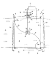
以下、城の堀に設定した調整水域から懸濁物質としてのアオコを採取する場合を例に、本発明による懸濁物質採取方法および装置の実施形態を説明する。図面中、図1は本発明による懸濁物質採取方法を実施するように配置された本発明装置を平面的に示す概略図、図2は図1中の円U内の部分を拡大して示す斜視図であって、本発明装置を構成するエンドレスロープとロープ案内部材(滑車)とシルトフェンスとの関係を示す図、図3は上記シルトフェンスの一端を支持している本発明装置による浮体の概略側面図である。 Hereinafter, the embodiment of the suspended substance collection method and apparatus according to the present invention will be described by taking, as an example, the case of collecting a giant sea urchin as a suspended substance from an adjusted water area set in a castle moat. In the drawings, FIG. 1 is a schematic diagram showing a plan view of the device of the present invention arranged to carry out the method for collecting suspended solids according to the present invention, and FIG. 2 is an enlarged view of a portion in a circle U in FIG. FIG. 3 is a perspective view showing a relationship between an endless rope, a rope guide member (pulley) and a silt fence constituting the apparatus of the present invention, and FIG. 3 shows a floating body according to the apparatus of the present invention supporting one end of the silt fence. It is a schematic side view.
図示の装置は、2つの岸辺B,Cを伴う堀Aの一方の岸辺Bに設置した移設可能の作業ヤードD、この作業ヤードDに隣接して岸辺Bに設置した移設可能のアオコ回収装置E、および、一方の端部が下記の吸入口に接続され、他方の端部が上記アオコ回収装置Eに接続され、中途に吸引ポンプPが設けてあるサクションホースFとそれぞれ協働するように配置される。上記アオコ回収装置Eは、内蔵した高分子フィルターによりアオコと水を分離し、分離したアオコを貯蔵容器あるいは次の処理工程へ向けて排出し、また分離した水を溶存酸素量増大処理に付した後、放水管Gを介して堀Aに戻すように作用する。 The illustrated apparatus is a transferable work yard D installed on one shore B of a moat A with two shores B and C, and a transferable sea cucumber recovery device E installed on the shore B adjacent to the work yard D. , And one end is connected to the following suction port, the other end is connected to the above-mentioned sea cucumber recovery device E, and arranged so as to cooperate with the suction hose F provided with the suction pump P in the middle. Is done. The above-mentioned sea cucumber recovery device E separates water and water using a built-in polymer filter, discharges the separated sea cucumber to a storage container or the next processing step, and subject the separated water to a dissolved oxygen amount increasing process. Then, it acts to return to the moat A through the water discharge pipe G.
上記のように設備D,E,F,G,Pと協働する本発明による懸濁物質採取装置1は、ロープ案内部材としての4つの滑車(円盤状の定滑車)2a,2b,2c,2d、これら滑車間に順次架け渡されたエンドレスロープ3、吸入口4を有する吸入口形成部材40(図3)を保持する浮体5、この浮体5と上記エンドレスロープ3との間に架け渡された2連のシルトフェンス6a,6bを有している。
As described above, the suspended matter collecting apparatus 1 according to the present invention, which cooperates with the facilities D, E, F, G, and P, includes four pulleys (disk-shaped constant pulleys) 2a, 2b, 2c as rope guide members. 2d, the
上記の滑車2a〜2dは、堀Aにアオコを採取すべく設定された調整水域Sの周囲に、この調整水域Sを取り囲むように間隔をおいて岸辺B,Cに設置されている。これら滑車は、滑車2bを例に図2に具体的に示すように、地面にアンカーピン2b2により固定された支持片2b1の上部に略垂直の回転軸2b3を有するように、従って略水平の姿勢で自由回転するように装着されており、従って滑車2bの案内溝に係合するロープ3は滑車2bで水平方向に方向変換される。他の滑車2a,2c,2dについても同様である。
The
上記滑車2a〜2dに環状に架け渡されたエンドレスロープ3は、作業ヤードD内に配置された2つの回転ドラム7a,7bに挟まれ摩擦接触しており、これら回転ドラムを回転させることによりエンドレスロープ3はその長手方向へ循環駆動せしめられる。回転ドラム7a,7bの回転は電動モータ8によって行われ、このモータ8の回転は制御装置9によって制御され、この制御装置は吸引ポンプPの下流側においてサクションホースFに接続された濁度計10から信号を受けるようになされている。
The
上記シルトフェンスは、シルトフェンス6aを例に図2および図3に具体的に示すように、長尺のフロート部6a1とこのフロート部から垂下するスカート部6a2とを有している。フロート部6a1は横断面円形の中実体であることが好ましいが、他の横断面形状であってもよく、また中空であってもよい。また、フロート部の材料は発泡スチロールが好ましいが、他の樹脂製材料であってもよい。スカート部6a2は例えば帆布にて製作され、下端に錘が取り付けられている。スカート部の垂下長さは、水深方向でのアオコの分布範囲或いは浮遊範囲を考慮して、この範囲を覆うのに十分な長さに決められている。
The silt fence has a
上記フロート部6a1の一方の端部は、図2に示すように、連結ロープ6a3および取付け具6a4を介してエンドレスロープ3に結合されている。取付け具6a4は滑車2bを通過する際に連結ロープ6a3が該滑車2bを逃げて、更には上記の回転ドラム7を逃げて通過することができるように屈曲した構成となされている。
As shown in FIG. 2, one end of the
図3に、図2よりも縮尺して示されている上記フロート部6a1の他方の端部は、連結ロープ6a5によって、浮体5の中央上部に回転可能に設けられた支持部材5aに結合されている。このようにして、シルトフェンス6aはエンドレスロープ3と浮体5との間に張り渡される。
The other end portion of the
シルトフェンス6aの上記の構成並びに結合の状況はシルトフェンス6bについても同様である。
The above-described configuration and connection state of the
上記浮体5は、図3に示すように、枠体5bと、この枠体5bに取り付けられた浮き部材5cとを有しており、枠体5bの上部には支持台5dが設けられ、この支持台の上部に上記支持部材5aが回転可能に軸受けされている。
As shown in FIG. 3, the floating
図3に示すように、上記浮体5は、その水平の枠部分5b1に、上記吸入口4を有する吸入口形成部材40を上下動可能に保持しており、その上下動は作動装置50によってもたらされるようになされている。この吸入口形成部材40は水面に対して垂直の軸線を有する筒状部材40aと、この筒状部材の上部に水平に取り付けられ、更にこの筒状部材から半径方向へ突出している円板状蓋体40bとを有しており、上記吸入口4は、円板状蓋体40bに隣接する筒状部材40aの上部範囲の周囲に複数個の開口として形成されている。筒状部材40aの下部は連結部材40cを介して上記サクションホースFに連結されており、従って上記吸入口4から筒状部材40a内へ水と共に吸い込まれるアオコは、連結部材40cと経てサクションホースFへ搬送される。
As shown in FIG. 3, the floating
次に、上記のように構成され配置された懸濁物質採取装置1により水域に広く漂うアオコを採取する方法について、主として図1を参照しつつ説明する。 Next, a method of collecting the sea cucumber drifting widely in the water area by the suspended substance collecting apparatus 1 constructed and arranged as described above will be described mainly with reference to FIG.
設定された調整水域Sを掘りAの他の水域から仕切るために、図1に示すように汚濁防止幕Ha,Hbが岸辺B,C間に事前に張り渡される。次いで、作業ヤードD内のモータ8を起動すると、回転ドラム7a,7bが回転せしめられ、この2つの回転ドラムに挟まれ摩擦接触しているエンドレスロープ3は、回転ドラム7a,7bの回転に従って、例えば矢印Tの方向へ循環駆動される。
In order to divide the set adjustment water area S from the other water areas of the digging A, the pollution prevention screens Ha and Hb are stretched between the shores B and C in advance as shown in FIG. Next, when the motor 8 in the work yard D is started, the
エンドレスロープ3に一端が連結されているシルトフェンス6a,6bは、エンドレスロープ3の循環動に従って浮体5を中心に旋回せしめられる。このとき、シルトフェンス6a,6bの回転は、外側のエンドレスロープ3に近い側で早く、内側の浮体5に近い側では遅くなり、この回転速度の差により水の流れは、速い方から遅い方へ、即ちシルトフェンス6a,6bに沿ってエンドレスロープ3側から浮体5方向へ向う水流れが発生し、その結果水域Sに浮遊するアオコは上記水流に乗せられて浮体5方向へ誘導され、従って吸入口4付近のアオコ濃度が次第に高まる。
The
また、ポンプPの作動により、吸入口4への流体の流入に伴って吸入口4の周辺に流体の流れが発生し、この流れは上記シルトフェンスにより発生せしめられる水流と共同し、アオコ誘導効果を高める。その際、上記作動部材50(図3)を操作し、吸入口形成部材40の水深位置を上下方向において調節し、アオコ濃度が最も高い分布層に吸入口4を位置せしめるようにすれば、アオコ採取効率が更に高まる。また、上記板状蓋体40bは、上記のように吸入口4の位置をアオコ高濃度層に対応させた際に、当該板状蓋体上方のアオコ含有が比較的希薄な層の流体が吸入口4へ流入するのを阻止する。
Further, when the pump P is operated, a fluid flow is generated around the suction port 4 as the fluid flows into the suction port 4, and this flow cooperates with the water flow generated by the silt fence, so To increase. At that time, if the operating member 50 (FIG. 3) is operated to adjust the water depth position of the suction
上記シルトフェンスのスカート部6a2(図2及び図3)は水深方向でのその垂下長さがアオコの分布範囲或いは浮遊範囲全体を十分にカバーするように決められているので、水域Sの平面的広がり方向及び深さ方向に浮遊するほぼ全てのアオコを上記シルトフェンスによる水流に乗せることができ、またスカート部の下部に錘が取り付けられていれば、スカート部6a2によるアオコ誘導効果が更に高められる。
Since the
このようにして吸入口4からは高濃度のアオコを含有する流体が吸入されることになり、水域Sから効率よくアオコが採取される。吸引された流体は、上述のようにサクションホースFを経てアオコ回収装置Eへ搬送される。 In this way, a fluid containing a high concentration of aquatic is sucked from the inlet 4, and aquatic can be efficiently collected from the water area S. The sucked fluid is transported to the water recovery device E through the suction hose F as described above.
水域Sでのアオコ採取が進み、濁度計10で計測されている流体の濁度が浄化達成の目安として設定された上記の許容値に達すると、濁度計10は制御装置9へ信号を送り、制御装置9はモータ8を停止する。制御装置9がポンプPを駆動するためのモータ(図示せず)にも接続されていれば、ポンプPの作動も同時に停止せしめられ、斯くして水域Sの浄化が達成される。
When aquatic sampling in the water area S progresses and the turbidity of the fluid measured by the
なお、本発明は上記実施の形態に限定されることなく、発明の趣旨を逸脱しない範囲で種々変更可能である。例えば、シルトフェンスは2連のものが示されているが、1連でもよく、3連以上であってもよい。 In addition, this invention is not limited to the said embodiment, A various change is possible in the range which does not deviate from the meaning of invention. For example, although two silt fences are shown, there may be one or more than three.
1 懸濁物質採取装置
2a,2b,2c,2d ロープ案内部材(滑車)
3 エンドレスロープ
4 吸入口
5 浮体
5a 支持部材
6a,6b シルトフェンス
7a,7b 回転ドラム
8 モータ
9 制御装置
10 濁度計
40 吸入口形成部材
50 作動部材
A 堀
B,C 岸辺
D 作業ヤード
E 懸濁物質処理装置(アオコ回収装置)
F サクションホース
G 放水管
S 調整水域
P 吸引ポンプ
1 Suspended
3 Endless rope 4
F Suction hose G Drain pipe S Adjustable water area P Suction pump
Claims (8)
前記懸濁物質を採取するべく設定された調整水域の周辺にその周方向に間隔を置いて複数個のロープ案内部材を配置し、
これらロープ案内部材にロープを順次架け渡し、環状に張設されたエンドレスロープとなし、
前記設定水域の中央部に前記吸入口を保持する浮体を配置し、
前記浮体と前記エンドレスロープとの間にシルトフェンスを張り渡し、
前記エンドレスロープを前記ロープ案内部材による案内のもとに循環駆動させ、これによって前記シルトフェンスを前記浮体を中心に水域面に沿って旋回動させ、旋回動する前記シルトフェンスにより前記水域に前記吸入口へ向う水流を発生させ、前記水域に浮遊する懸濁物質を前記水流に乗せて前記吸入口へ誘導することを特徴とする懸濁物質採取方法。 In the suspended matter collection method for guiding suspended substances drifting in a wide area in the water area toward the collection inlet, and collecting by suction from the inlet,
A plurality of rope guide members are arranged at intervals in the circumferential direction around the adjusted water area set to collect the suspended matter,
Rope is passed over these rope guide members one after another, endless rope stretched in an annular shape,
A floating body that holds the suction port is disposed at the center of the set water area,
A silt fence is stretched between the floating body and the endless rope,
The endless rope is circulated and driven under the guidance of the rope guide member, whereby the silt fence is swung along the surface of the water area around the floating body, and the suction is sucked into the water area by the revolving silt fence. A method for collecting suspended solids, characterized in that a water flow toward the mouth is generated, and suspended solids suspended in the water area are placed on the water flow and guided to the suction port.
濁度が浄化達成の目安として設定された許容値に達するまで前記シルトフェンスの旋回動を継続する、
ことを特徴とする請求項1又は2に記載の懸濁物質採取方法。 Measure the turbidity of suspended solid-containing water sucked from the inlet,
Continue turning the silt fence until the turbidity reaches an allowable value set as a guideline for purification.
The suspended substance collection method according to claim 1 or 2, characterized in that.
懸濁物質を採取するべく設定された調整水域の周辺にその周方向に間隔を置いて配置される複数個のロープ案内部材と、
前記複数個のロープ案内部材に順次架け渡され、環状に張設されるエンドレスロープと、
前記吸入口を形成している吸入口形成部材を保持し、前記調整水域の中央部に配置される浮体と、
前記エンドレスロープと前記浮体との間に張り渡される少なくとも1つのシルトフェンスと、
前記エンドレスロープを循環駆動する駆動装置と、
を有していることを特徴とする懸濁物質採取装置。 In the suspended matter collection device that guides the suspended matter drifting in a wide area in the water area to the suction port for collection, and sucks and collects it from the suction port.
A plurality of rope guide members arranged at intervals in the circumferential direction around the adjusted water area set to collect suspended solids;
An endless rope that is sequentially stretched over the plurality of rope guide members and stretched annularly;
Holding a suction port forming member forming the suction port, and a floating body disposed in a central portion of the adjustment water area;
At least one silt fence stretched between the endless rope and the floating body;
A driving device for circulatingly driving the endless rope;
Suspended substance collection device characterized by having.
前記吸入口形成部材に接続され吸入口から吸入された懸濁物質含有水を懸濁物質処理装置へポンプ搬送するサクションホースが懸濁物質含有水の濁度を測定する濁度計と接続されており、
前記濁度計と前記電動モータは、該濁度計からの濁度信号に応じて該電動モータの回転を制御する制御装置を介して接続されている、
ことを特徴とする請求項4又は5に記載の懸濁物質採取装置。 The driving device includes a rotating drum that is in frictional contact with the endless rope at an intermediate position between the two rope guide members, and an electric motor that rotationally drives the rotating drum;
A suction hose connected to the suction port forming member and pumping the suspended matter-containing water sucked from the suction port to the suspended matter treatment apparatus is connected to a turbidimeter for measuring the turbidity of the suspended matter-containing water. And
The turbidimeter and the electric motor are connected via a control device that controls the rotation of the electric motor in accordance with a turbidity signal from the turbidimeter.
The suspended substance collection device according to claim 4 or 5, wherein
前記スカート部の垂下長さが水深方向での懸濁物質の浮遊範囲より長く選定されていること、
を特徴とする請求項4〜7項の何れか1つに記載の懸濁物採取装置。 The silt fence has a float portion that is stretched between the floating body and the endless rope, and a skirt portion that hangs down from the float portion,
The hanging length of the skirt portion is selected to be longer than the suspended range of suspended solids in the water depth direction,
The suspension collecting apparatus according to any one of claims 4 to 7, wherein
Priority Applications (1)
| Application Number | Priority Date | Filing Date | Title |
|---|---|---|---|
| JP2006016032A JP4755907B2 (en) | 2006-01-25 | 2006-01-25 | Suspended material collection method and apparatus |
Applications Claiming Priority (1)
| Application Number | Priority Date | Filing Date | Title |
|---|---|---|---|
| JP2006016032A JP4755907B2 (en) | 2006-01-25 | 2006-01-25 | Suspended material collection method and apparatus |
Publications (3)
| Publication Number | Publication Date |
|---|---|
| JP2007197955A JP2007197955A (en) | 2007-08-09 |
| JP2007197955A5 JP2007197955A5 (en) | 2009-02-26 |
| JP4755907B2 true JP4755907B2 (en) | 2011-08-24 |
Family
ID=38452823
Family Applications (1)
| Application Number | Title | Priority Date | Filing Date |
|---|---|---|---|
| JP2006016032A Expired - Fee Related JP4755907B2 (en) | 2006-01-25 | 2006-01-25 | Suspended material collection method and apparatus |
Country Status (1)
| Country | Link |
|---|---|
| JP (1) | JP4755907B2 (en) |
Families Citing this family (1)
| Publication number | Priority date | Publication date | Assignee | Title |
|---|---|---|---|---|
| JP6491483B2 (en) * | 2015-01-16 | 2019-03-27 | アサヒ産業有限会社 | Silt fence with water purification effect |
Family Cites Families (3)
| Publication number | Priority date | Publication date | Assignee | Title |
|---|---|---|---|---|
| JP2000303438A (en) * | 1999-04-21 | 2000-10-31 | Shinko Electric Co Ltd | Water purifying device and water purifying method |
| JP2004008948A (en) * | 2002-06-07 | 2004-01-15 | Saeki Kensetsu Kogyo Co Ltd | Underwater floating matter collection apparatus |
| JP4741347B2 (en) * | 2005-11-15 | 2011-08-03 | 中国電力株式会社 | Water purification facilities |
-
2006
- 2006-01-25 JP JP2006016032A patent/JP4755907B2/en not_active Expired - Fee Related
Also Published As
| Publication number | Publication date |
|---|---|
| JP2007197955A (en) | 2007-08-09 |
Similar Documents
| Publication | Publication Date | Title |
|---|---|---|
| RU2417815C2 (en) | Sediment collection and/or removal device | |
| JP4904134B2 (en) | Suspended material collection method and suspended material collection device | |
| US6432302B1 (en) | Water circulation apparatus system and method | |
| WO2006011921A2 (en) | Method and system for filtering sediment-bearing fluids | |
| KR101027716B1 (en) | Moving type algae remove system for water area of stagnation | |
| JP4755907B2 (en) | Suspended material collection method and apparatus | |
| JP2008138441A (en) | Suspended matter collecting apparatus | |
| KR101034651B1 (en) | Water circulating device | |
| JP2021137672A (en) | Algae removal device and algae treatment system | |
| JP4741347B2 (en) | Water purification facilities | |
| JP5171508B2 (en) | Suspended suspended matter collection device | |
| KR101182753B1 (en) | The High Speed Screens with floating apparatus | |
| JP2004008948A (en) | Underwater floating matter collection apparatus | |
| JP6896537B2 (en) | Dredging structure | |
| JP4579140B2 (en) | Floating body for collecting suspended solids and method of using the floating body for collecting suspended solids | |
| JP2003117317A (en) | Water treatment apparatus | |
| KR200346698Y1 (en) | Disposal facilities Structure in the stream | |
| KR101452155B1 (en) | Floating removal device using water power | |
| KR101442232B1 (en) | A float recovery processing unit | |
| JP4776520B2 (en) | Suspended material collection device | |
| CN112709189B (en) | Automatic flow regulating system for black and odorous water body in river channel | |
| KR20080046304A (en) | Water cleaning apparatus | |
| KR101208816B1 (en) | Water purification apparatus in river using the micro bubble | |
| JP2521403B2 (en) | Purification device | |
| KR101500715B1 (en) | Algae collecting device |
Legal Events
| Date | Code | Title | Description |
|---|---|---|---|
| A521 | Written amendment |
Free format text: JAPANESE INTERMEDIATE CODE: A523 Effective date: 20090114 |
|
| A621 | Written request for application examination |
Free format text: JAPANESE INTERMEDIATE CODE: A621 Effective date: 20090114 |
|
| A977 | Report on retrieval |
Free format text: JAPANESE INTERMEDIATE CODE: A971007 Effective date: 20110516 |
|
| TRDD | Decision of grant or rejection written | ||
| A01 | Written decision to grant a patent or to grant a registration (utility model) |
Free format text: JAPANESE INTERMEDIATE CODE: A01 Effective date: 20110524 |
|
| A01 | Written decision to grant a patent or to grant a registration (utility model) |
Free format text: JAPANESE INTERMEDIATE CODE: A01 |
|
| A61 | First payment of annual fees (during grant procedure) |
Free format text: JAPANESE INTERMEDIATE CODE: A61 Effective date: 20110530 |
|
| FPAY | Renewal fee payment (event date is renewal date of database) |
Free format text: PAYMENT UNTIL: 20140603 Year of fee payment: 3 |
|
| R150 | Certificate of patent or registration of utility model |
Ref document number: 4755907 Country of ref document: JP Free format text: JAPANESE INTERMEDIATE CODE: R150 Free format text: JAPANESE INTERMEDIATE CODE: R150 |
|
| FPAY | Renewal fee payment (event date is renewal date of database) |
Free format text: PAYMENT UNTIL: 20140603 Year of fee payment: 3 |
|
| S111 | Request for change of ownership or part of ownership |
Free format text: JAPANESE INTERMEDIATE CODE: R313117 |
|
| FPAY | Renewal fee payment (event date is renewal date of database) |
Free format text: PAYMENT UNTIL: 20140603 Year of fee payment: 3 |
|
| R360 | Written notification for declining of transfer of rights |
Free format text: JAPANESE INTERMEDIATE CODE: R360 |
|
| FPAY | Renewal fee payment (event date is renewal date of database) |
Free format text: PAYMENT UNTIL: 20140603 Year of fee payment: 3 |
|
| R370 | Written measure of declining of transfer procedure |
Free format text: JAPANESE INTERMEDIATE CODE: R370 |
|
| S111 | Request for change of ownership or part of ownership |
Free format text: JAPANESE INTERMEDIATE CODE: R313117 |
|
| R350 | Written notification of registration of transfer |
Free format text: JAPANESE INTERMEDIATE CODE: R350 |
|
| R250 | Receipt of annual fees |
Free format text: JAPANESE INTERMEDIATE CODE: R250 |
|
| R250 | Receipt of annual fees |
Free format text: JAPANESE INTERMEDIATE CODE: R250 |
|
| R250 | Receipt of annual fees |
Free format text: JAPANESE INTERMEDIATE CODE: R250 |
|
| R250 | Receipt of annual fees |
Free format text: JAPANESE INTERMEDIATE CODE: R250 |
|
| R250 | Receipt of annual fees |
Free format text: JAPANESE INTERMEDIATE CODE: R250 |
|
| R250 | Receipt of annual fees |
Free format text: JAPANESE INTERMEDIATE CODE: R250 |
|
| R250 | Receipt of annual fees |
Free format text: JAPANESE INTERMEDIATE CODE: R250 |
|
| LAPS | Cancellation because of no payment of annual fees |