JP4753942B2 - Optical proximity effect correction in raster scanning printing based on corner fitting template - Google Patents
Optical proximity effect correction in raster scanning printing based on corner fitting template Download PDFInfo
- Publication number
- JP4753942B2 JP4753942B2 JP2007519490A JP2007519490A JP4753942B2 JP 4753942 B2 JP4753942 B2 JP 4753942B2 JP 2007519490 A JP2007519490 A JP 2007519490A JP 2007519490 A JP2007519490 A JP 2007519490A JP 4753942 B2 JP4753942 B2 JP 4753942B2
- Authority
- JP
- Japan
- Prior art keywords
- pixel
- corner
- grayscale
- pixels
- square
- Prior art date
- Legal status (The legal status is an assumption and is not a legal conclusion. Google has not performed a legal analysis and makes no representation as to the accuracy of the status listed.)
- Expired - Fee Related
Links
- 238000012937 correction Methods 0.000 title claims description 146
- 230000000694 effects Effects 0.000 title description 9
- 230000003287 optical effect Effects 0.000 title description 8
- 238000000034 method Methods 0.000 claims abstract description 52
- 238000001514 detection method Methods 0.000 claims description 83
- 239000000872 buffer Substances 0.000 claims description 49
- 230000008569 process Effects 0.000 claims description 21
- 238000003491 array Methods 0.000 claims description 6
- 230000035945 sensitivity Effects 0.000 claims description 4
- 230000003247 decreasing effect Effects 0.000 claims description 2
- 230000007547 defect Effects 0.000 abstract description 14
- 238000001459 lithography Methods 0.000 abstract description 7
- 238000004904 shortening Methods 0.000 abstract description 4
- 238000012545 processing Methods 0.000 description 21
- 238000013459 approach Methods 0.000 description 20
- 238000005070 sampling Methods 0.000 description 8
- 238000013461 design Methods 0.000 description 4
- 238000010586 diagram Methods 0.000 description 4
- 230000014509 gene expression Effects 0.000 description 4
- 230000005855 radiation Effects 0.000 description 4
- 238000012546 transfer Methods 0.000 description 3
- 238000012935 Averaging Methods 0.000 description 2
- 238000006243 chemical reaction Methods 0.000 description 2
- 238000010894 electron beam technology Methods 0.000 description 2
- 238000005516 engineering process Methods 0.000 description 2
- 238000004519 manufacturing process Methods 0.000 description 2
- 239000004065 semiconductor Substances 0.000 description 2
- 238000012360 testing method Methods 0.000 description 2
- 238000009825 accumulation Methods 0.000 description 1
- 230000001154 acute effect Effects 0.000 description 1
- 238000004220 aggregation Methods 0.000 description 1
- 230000002776 aggregation Effects 0.000 description 1
- 230000003466 anti-cipated effect Effects 0.000 description 1
- 230000008901 benefit Effects 0.000 description 1
- 230000001427 coherent effect Effects 0.000 description 1
- 238000007689 inspection Methods 0.000 description 1
- 230000001678 irradiating effect Effects 0.000 description 1
- 239000000203 mixture Substances 0.000 description 1
- 238000005457 optimization Methods 0.000 description 1
- 239000002245 particle Substances 0.000 description 1
- 229920002120 photoresistant polymer Polymers 0.000 description 1
- 239000000758 substrate Substances 0.000 description 1
- 230000007704 transition Effects 0.000 description 1
Images


Classifications
-
- G06T5/73—
-
- G—PHYSICS
- G06—COMPUTING; CALCULATING OR COUNTING
- G06T—IMAGE DATA PROCESSING OR GENERATION, IN GENERAL
- G06T7/00—Image analysis
- G06T7/10—Segmentation; Edge detection
- G06T7/13—Edge detection
-
- H—ELECTRICITY
- H04—ELECTRIC COMMUNICATION TECHNIQUE
- H04N—PICTORIAL COMMUNICATION, e.g. TELEVISION
- H04N1/00—Scanning, transmission or reproduction of documents or the like, e.g. facsimile transmission; Details thereof
- H04N1/40—Picture signal circuits
- H04N1/409—Edge or detail enhancement; Noise or error suppression
- H04N1/4092—Edge or detail enhancement
-
- G—PHYSICS
- G06—COMPUTING; CALCULATING OR COUNTING
- G06T—IMAGE DATA PROCESSING OR GENERATION, IN GENERAL
- G06T2207/00—Indexing scheme for image analysis or image enhancement
- G06T2207/20—Special algorithmic details
- G06T2207/20112—Image segmentation details
- G06T2207/20164—Salient point detection; Corner detection
Landscapes
- Engineering & Computer Science (AREA)
- Computer Vision & Pattern Recognition (AREA)
- Physics & Mathematics (AREA)
- General Physics & Mathematics (AREA)
- Theoretical Computer Science (AREA)
- Multimedia (AREA)
- Signal Processing (AREA)
- Image Processing (AREA)
Abstract
Description
発明の分野
[0001]本発明の実施形態は、一般に、パターン印刷に使用されるリソグラフィ・システム又は半導体ウエハ上のマスク、より具体的には、それにより印刷されたパターン特徴部の鋭敏さを改善することに関する。
Field of Invention
[0001] Embodiments of the present invention generally relate to a lithography system used for pattern printing or a mask on a semiconductor wafer, and more particularly to improving the sensitivity of printed pattern features. .
関連技術の説明
[0002]集積回路のフォトリソグラフィ製造において放射粒子エネルギに敏感なレジストは、所定のパターンで露光され、回路特徴部を画成する。一部の場合、エネルギは、パターンを含むマスクを通過し、半導体ボディ上のフォトレジストを選択的に露光する。他の場合、レジストはマスク基板上にあり、放射エネルギ自体の方向は、レジスト内でパターンを画成する為に制御される。紫外線、可視光、コヒーレント光、X線、電子ビーム(Eビーム)を含む幾つかの放射エネルギ源が使用されてきた。
Explanation of related technology
[0002] In photolithographic manufacturing of integrated circuits, resists that are sensitive to radiant particle energy are exposed in a predetermined pattern to define circuit features. In some cases, energy passes through a mask containing a pattern and selectively exposes the photoresist on the semiconductor body. In other cases, the resist is on the mask substrate and the direction of the radiant energy itself is controlled to define a pattern in the resist. Several radiant energy sources have been used, including ultraviolet light, visible light, coherent light, X-rays, and electron beams (E-beams).
[0003]集積回路のフォトリソグラフィ製造の為の一つのシステムは、本発明の譲受人に譲渡された"Laser Pattern Generation Apparatus"と題する米国特許第4,796,038号に説明されている。ここで説明されたシステムにおいて、レーザービームを照射し、レーザービームに対してワークピースを動かすことにより、ワークピースに回路パターンが書き込まれる。そのようなシステムにおいて、露光された場所の各々におけるレーザービームの強度または投与量は、ピクセル・アレイ(一般にピクセル・マップと呼ばれる)により制御されるが、各ピクセルの値は、露光された、対応する場所における投与量を決定する。露光の投与量またはレベルは、通常、対応するピクセルに与えられたグレースケール値(通常、ゼロから最大値)として表わされるが、ゼロは投与量がゼロ又は白、最大値は投与量の全て又は黒に対応する。 [0003] One system for photolithographic fabrication of integrated circuits is described in US Pat. No. 4,796,038 entitled “Laser Pattern Generation Apparatus” assigned to the assignee of the present invention. In the system described herein, a circuit pattern is written on the workpiece by irradiating the laser beam and moving the workpiece relative to the laser beam. In such a system, the intensity or dose of the laser beam at each exposed location is controlled by a pixel array (commonly referred to as a pixel map), where the value of each pixel is the corresponding, exposed Determine the dose at the place to be. The dose or level of exposure is usually expressed as a grayscale value (usually zero to maximum) given to the corresponding pixel, where zero is zero or white and maximum is all or Corresponds to black.
[0004]ピクセル・マップは、ラスタライゼーション処理により生成されるが、グラフィック・デザイン・システム(GDS)又はMEBESフォーマットファイルのようなパターンを示すデータファイルは、(「ラスタライジング・エンジン」と呼ばれる構成要素を使用して)パターンが存在するピクセルを決定することにより、個々のピクセル値に変換される。データファイルは、パターン特徴部の個々の鋭角部(vertices)を識別するデータを備え通常、階層的なフォーマット内で画像を示す。そのようなラスタライゼーション処理を実行する為の技術や回路の一実施例は、本発明の譲受人に譲渡され、参考の為に本願に組み込まれている、"Rasterizer for A Pattern Generation Apparatus"と題する米国特許第5,553,170号に説明されている。 [0004] A pixel map is generated by a rasterization process, but a data file that shows a pattern, such as a graphic design system (GDS) or MEBES format file, is a component called a “rasterizing engine”. Are converted into individual pixel values by determining the pixels in which the pattern exists. A data file comprises data that identifies individual vertices of pattern features and typically represents an image in a hierarchical format. One embodiment of techniques and circuitry for performing such rasterization processing is entitled "Rasterizer for A Pattern Generation Apparatus", assigned to the assignee of the present invention and incorporated herein by reference. U.S. Pat. No. 5,553,170.
[0005]リソグラフィ・システムを用いてパターンを書き込むとき、放射された電子又はレーザービーム内に供給される電力に関連した、例えば回折限定波長効果や電気光学的効果のような多くの境界や端部の影響が、実際に書き込まれたパターン内で欠陥を生じさせる場合がある。ラスタライゼーション処理で使用されるサブサンプリング技術、書き込みの為のガウス成形ビーム使用のような書き込み処理のファクタも、これらの欠陥に貢献する場合がある。これらの欠陥は、鋭利でない縁の為にライン短縮(通常、ライン端部の短縮と呼ばれる。)や丸くなった角を含む場合がある。 [0005] When writing a pattern using a lithography system, many boundaries and edges, such as diffraction limited wavelength effects and electro-optic effects, related to the power delivered in the emitted electron or laser beam May cause defects in the actually written pattern. Write processing factors such as the sub-sampling techniques used in the rasterization process and the use of a Gaussian shaped beam for writing may also contribute to these defects. These defects may include line shortening (usually referred to as line end shortening) and rounded corners due to non-sharp edges.
[0006]丸くなった角を補償する一つの方法は、角の領域に近接する露光領域を増やす為に、有効に追加のジオメトリを含めるようにデータファイルを操作することを伴う。この方法は、図1に示されているが、図1は、パターン111のデータファイル110をラスタライジングする標準処理フロー102と、「ジオメトリ・ベース」の光学的近接補正(OPC)を含む処理フロー104の両方を示す。図示ように、標準処理フロー102において、データファイル110は、ラスタライゼーション処理によりビット・マップ120に変換される。しかし、前述した境界の影響のため、ビット・マップ120に基づくパターンの書き込みは、丸くなった角132sを有する最終書き込みパターン130sを生じさせる(比較のため、理想的な「形」の角134が点線で示されている)。図1Aにおける丸い角132Sの拡大図で示された、角の丸みを定量化する為に使用される一つの測定基準は、理想的な角の先端と、実際の丸い角における最も近い場所との間の距離であり、一般に角の後退(CPB:Corner Pull Back)と呼ばれている。
[0006] One method of compensating for rounded corners involves manipulating the data file to effectively include additional geometry to increase the exposure area adjacent to the corner area. This method is illustrated in FIG. 1, which shows a
[0007]ジオメトリ・ベースのOPC処理フロー104において、データファイル110sは、シェリーフ112をパターン111の角に加える為に操作され、新しいデータファイル110Gが生じるが、これが、新しいビット・マップ120Gを形成するようにラスタライズされる。シェリーフ112のため、この新しいビット・マップ120Gは、パターンの角の近くに配置されたゼロでない値を持つ追加ピクセルを有する。その結果、ビット・マップ120Gに基づくパターン書き込みは、より丸くない角132Gを備えて書き込まれたパターン130Gが生じ、理想的な角134に向けて、外側に効果的に伸ばされ、角領域を「回復」即ちCPBを減少させる。
In [0007] the geometry-based
[0008]残念なことに、このジオメトリ・ベースのOPC処理に伴う多くの短所が存在する。一つの短所は、シェリーフ112の追加のため、表示されなければならない角の数が増え、データファイル110Gは比例して増大することである。例えば、図1に示された単純な実施例において、当初の形状111は、4つの角しか持たない。しかし、シェリーフ112の各々は、追加の2つの外側(凸状)角と2つの内側(凹状)角とをパターン111の当初の角の各々に加える。前述したように、これらの角は、通常、データファイル110G内で鋭角部として表示されているので、これらの追加の角は、結果として5のファクタだけデータファイル110Gを増大させる。データファイル110Gが増大するにつれて、パターンデータをラスタライザーに転送するのに必要な時間、すなわち、全体の処理時間(印刷する為の時間)は、比例して増大する可能性がある。
[0008] Unfortunately, there are many disadvantages associated with this geometry-based OPC process. One disadvantage is, for additional Sherifu 112 increases the number of corners should be displayed, the
[0009]ジオメトリ・ベースOPCに伴う他の短所は、ラスタライゼーション・エンジンに依存し、一部の欠陥に対し良好に補正可能な一定の理想的なピクセル構成が、シェリーフ112のような単純なジオメトリの追加のために達成できないことである。関連する短所は、所望のピクセル構成を達成する為に複雑なジオメトリの追加に努めても、それに伴ってデータファイルが増大するので、データ移動に伴う前述した問題を悪化させる。 [0009] Another disadvantage associated with geometry-based OPC relies on the rasterization engine, where a certain ideal pixel configuration that can be well corrected for some defects is a simple geometry such as Sheef 112. Because of the addition of The associated disadvantages exacerbate the aforementioned problems associated with data movement, as the effort to add complex geometry to achieve the desired pixel configuration increases the data file associated therewith.
[0010]したがって、リソグラフィにより書き込まれたパターンにおいて、丸くなった角のような欠陥の補正用技術を改善する必要がある。そのような技術は、データ移動にほとんど影響が無いか、何も影響がないことが好ましい。 [0010] Accordingly, there is a need to improve techniques for correcting defects such as rounded corners in patterns written by lithography. Such techniques preferably have little or no effect on data movement.
[0011]本発明は、一般に、リソグラフィを介して印刷されたパターン内の角を補正する為の方法およびシステムを提供する。 [0011] The present invention generally provides a method and system for correcting corners in a pattern printed via lithography.
[0012]一実施形態は、高感度記録面に書き込まれるパターンの角を調整する為の方
法を提供する。この方法は、一般に:パターンの画像に対しデータファイルをラスタライズすることによりグレースケールのピクセル・マップを生成するステップであって、上記ピクセル・マップは、0から整数Nの間の対応グレースケール値を有するピクセル・アレイを備える、上記ステップと;上記グレースケールのピクセル・マップ内の対応ピクセルのグレースケール値に依存して、0か1のブーリアン値を有するピクセル・アレイを備えるブーリアン型ピクセル・マップを生成するステップと;角に対応するピクセル用テンプレートに、角型ピクセルに対応するピクセルと囲んでいるピクセルを含む上記ブーリアン型マップ内のピクセル・アレイを比較することにより、上記グレースケールのピクセル・マップ内で角型ピクセルを検出するステップと;角型ピクセルと、角型ピクセルに隣接するピクセルのうち少なくとも一つのグレースケール値を調整するステップと;を備える。
[0012] One embodiment provides a method for adjusting the corners of a pattern written on a sensitive recording surface. The method generally includes: generating a grayscale pixel map by rasterizing a data file for an image of a pattern, the pixel map having a corresponding grayscale value between 0 and the integer N. A Boolean pixel map comprising a pixel array having a Boolean value of 0 or 1, depending on the grayscale value of the corresponding pixel in the grayscale pixel map; Generating a grayscale pixel map by comparing a pixel array in the Boolean map including a pixel template corresponding to a corner and a surrounding pixel to a pixel corresponding to a corner pixel; Detecting a square pixel in Adjusting a gray scale value of at least one of the corner pixels and pixels adjacent to the corner pixels.
[0013]他の実施形態は、高感度記録面に書き込まれるパターンの角を調整する為の方法を提供する。この方法は、一般に:上記パターンの画像に対しデータファイルをラスタライズすることによりグレースケールのピクセル・マップを生成するステップであって、上記ピクセル・マップは、対応するグレースケール値を有するピクセル・アレイを備える、上記ステップと;ブーリアン値を有するピクセル・アレイを備えるブーリアン型ピクセル・マップを生成するステップであって、1のブーリアン値は、0でないグレースケールを有するグレースケールのピクセル・マップ内の対応するピクセルを示し、0のブーリアン値は、0のグレースケール値を有するグレースケールのピクセル・マップ内の対応するピクセルを示す、上記ステップと;各々が潜在的角形ピクセルにセンタリングされた上記ブーリアン型ピクセル・マップ内の一以上のピクセル・アレイを、凸状角および凹状角の両方に対応する複数のテンプレートと同時に比較することにより、上記グレースケールのピクセル・マップ内で角形ピクセルを検出するステップと;検出された角形ピクセルと、検出された角形ピクセルに隣接するピクセルのうち少なくとも一つのグレースケール値を調整するステップと;を備える。 [0013] Another embodiment provides a method for adjusting the corners of a pattern written on a high sensitivity recording surface. The method generally includes: generating a grayscale pixel map by rasterizing a data file for the pattern image, wherein the pixel map includes a pixel array having a corresponding grayscale value. Generating a Boolean pixel map comprising a pixel array having Boolean values, wherein a Boolean value of 1 corresponds to a grayscale pixel map having a non-zero gray scale. A Boolean value of 0 indicating the corresponding pixel in a grayscale pixel map having a grayscale value of 0; and the Boolean pixel, each centered on a potential square pixel One or more in the map Detecting a square pixel in the grayscale pixel map by simultaneously comparing the xel array with a plurality of templates corresponding to both convex and concave corners; Adjusting a grayscale value of at least one of the pixels adjacent to the detected square pixel.
[0014]他の実施形態は、ラスタライザー、論理回路、角検出ユニット、角補正ユニットを一般に含む、抵抗面にパターンを書き込む為のシステムを提供する。上記ラスタライザーは、一般に、上記パターンの画像に対するデータファイルからグレースケールのピクセル・マップを生成するように構成され、前記グレースケール・マップは、対応するグレースケール値を有するピクセル・アレイを備える。上記論理回路は、一般に、上記グレースケールのピクセル・マップ内の対応するピクセルのグレースケール値に依存して、0か1のブーリアン値を有するピクセル・アレイを備えるブーリアン型ピクセル・マップを生成する。上記角検出ユニットは、一般に 上記ブーリアン型ピクセル・マップ内のピクセル・アレイを、角に対応するピクセルの角用テンプレートと比較することにより、グレースケールのピクセル・マップ内で角形ピクセルを検出するように構成されている。上記角補正ユニットは、一般に、角形ピクセルと、角形ピクセルに隣接するピクセルのうち少なくとも一つのグレースケールのピクセル・マップ内でグレースケール値を調整するように構成されている。 [0014] Another embodiment provides a system for writing a pattern on a resistive surface that generally includes a rasterizer, logic circuitry, a corner detection unit, and a corner correction unit. The rasterizer is generally configured to generate a grayscale pixel map from a data file for the pattern image, the grayscale map comprising a pixel array having a corresponding grayscale value. The logic circuit generally generates a Boolean pixel map comprising a pixel array having a Boolean value of 0 or 1, depending on the grayscale value of the corresponding pixel in the grayscale pixel map. The corner detection unit generally detects corner pixels in a grayscale pixel map by comparing the pixel array in the Boolean pixel map with a corner template for the pixel corresponding to the corner. It is configured. The corner correction unit is generally configured to adjust the grayscale value in a pixel map of at least one of the square pixels and pixels adjacent to the square pixels.
[0015]本発明の前述された特徴が詳細に理解し得る方式で、簡単に前述された本発明の詳細な説明は、添付図面に一部が示された実施形態を参照して行われる。しかし、添付された図面は、本発明の典型的な実施形態だけを示すので、本発明の範囲を限定するものではなく、本発明は、他の有効な実施形態を許容することに注意すべきである。 [0015] The foregoing detailed description of the invention, briefly described above, will be made with reference to the embodiments that are partially illustrated in the accompanying drawings, wherein the foregoing features of the invention can be understood in detail. However, it should be noted that the accompanying drawings show only typical embodiments of the present invention and are not intended to limit the scope of the present invention, and that the present invention allows other useful embodiments. It is.
[0044]本発明の実施形態は、一般に、放射されたビーム(レーザや電子ビームなど)を使用してリソグラフィを介して形成されたパターンにおいて、欠陥(丸くなった角、ライン端部短縮など)を補正する為の方法および装置を提供する。追加のジオメトリオブジェクトを含めるようにパターンのデータファイルを操作することにより、そのような欠陥を補償するというより、むしろ、欠陥は、ピクセル・マップのグレースケール値を操作することにより、「後のラスタライゼーション」の為に補償される。その結果、データファイルの大きさは、増えず、データの転送時間は影響されない。 [0044] Embodiments of the present invention generally provide defects (such as rounded corners, line end shortening, etc.) in patterns formed via lithography using emitted beams (such as lasers or electron beams). A method and apparatus for correcting Rather than compensating for such defects by manipulating the pattern's data file to include additional geometric objects, rather than manipulating the grayscale values in the pixel map, the defects can be Is compensated for. As a result, the size of the data file does not increase and the data transfer time is not affected.
[0045]欠陥の補償をラスタライゼーション後に実行することにより、角付近の投与量を操作(増加または減少)するように達成可能な実際のピクセル構成において、より大きな自由度を与えることが可能である。さらに、本願で説明されるように、ピクセル・ベースの欠陥の補償は、パターンの地域領域で実行可能であり、処理を分散可能にする。例えば、欠陥の補償がソフトウェアで実行されるとき、並列に作用する複数のプロセッサで処理は分散可能であり、プロセッサの各々はパターン残部を知る必要がなく、パターンの比較的小さな部分で動作する。同様に、欠陥補償がハードウェアで実行されるとき、並列に作用する複数のハードウェア構成要素間で処理は分散可能である。 [0045] By performing defect compensation after rasterization, it is possible to provide greater freedom in actual pixel configurations that can be achieved to manipulate (increase or decrease) dose near the corner. . In addition, as described herein, pixel-based defect compensation can be performed in the local region of the pattern, allowing processing to be distributed. For example, when defect compensation is performed in software, processing can be distributed across multiple processors acting in parallel, each of which does not need to know the rest of the pattern and operates on a relatively small portion of the pattern. Similarly, when defect compensation is performed in hardware, processing can be distributed among multiple hardware components acting in parallel.
ピクセル・ベースの角増強
[0046]図2は、リソグラフィを介してパターンを書き込む為の「ピクセル・ベース」の光学近接効果補正(OPC)を含む処理フロー202を示す。図示のように、データファイル110sは、標準フロー102にあるように、ラスタライゼーション処理によりビット・マップ120sに変換可能である。しかし、パターン111を書き込む為に、丸くなった角132sが生じ得る上記標準ビット・マップ120sを使用するのではなく、画質向上(enhanced)ビット・マップ120pが使用される。画質向上されるビット・マップ120pは、標準ビット・マップ120sにおいてピクセルの様々なグレースケール値を操作することにより生成される。グレースケール値は、本願で説明される様々な技術を使用して操作可能であり、パターンを書き込むとき角形ピクセルの近傍や、角形ピクセルにおいて供給されたエネルギの投与量の修正に努め、或いは、パターン111の理想的な角に、かなり密接に近付く角132pの達成に努める。
Pixel-based angular enhancement
FIG. 2 illustrates a
[0047]図3は、処理フロー202の一部として実行可能である典型的な操作300を示す。操作300は、書き込まれるパターンのデータファイルを受け取ることにより、ステップ302で始まる。データファイルは、パターンのジオメトリ特徴部を示すのに適した、あらゆるファイルフォーマットが可能であり、例えば、グラフィック・デザイン・システム(GDS)、MEBESフォーマットがある。ステップ304では、グレースケール値でピクセルのマップを作成する為に、データファイルがラスタライズされる。一部の実施形態に対し、ピクセルはサブピクセル・アレイから構成され、ラスタライゼーション処理は、パターンがカバーするサンプル・サブピクセル(又はサブサンプル)の限定数をどれだけ多く決定するステップを伴う場合がある。その後、各ピクセルに対してグレースケール値を設定することは、先に言及された米国特許第5,533,170号に説明されたようにカバーされたサブサンプルの全てを数えることを実質的に伴う場合がある。換言すると、一般に、パターンによりカバーされるピクセルの領域が大きくなるほど、より高いグレースケール値になる。
FIG. 3 illustrates an
[0048]ステップ306では、パターンの角が上に横たわるピクセル(以下、「角形ピクセル」という。)が識別される。ステップ308では、識別された角形ピクセル及び/又は隣接ピクセルのグレースケール値が調整される。これらの角形ピクセルを検出し補正することは、丸くなった角のピクセル・ベース補正に伴う基本ステップであるが、数多くの異なるアプローチが各々を達成する為に取られてもよい。全体的に説明されるように、各々に対し取るべき正確なアプローチを決定することは、様々な考慮事項を伴い、コストとパフォーマンスとのトレードオフを含む。
[0048] In
[0049]角形ピクセルを検出する難題は、図4Aを参照して例示可能であるが、図4Aは、ピクセル402のグリッド400の上に横たわる典型的パターン411を示す。示されるように、パターン411は、5つの凸状(外側)角404と一つの凹状(内側)角406を有する。これらの角が含まれるピクセルは、見る者にとって容易に識別可能であるが、必要であるものは、これらの角形ピクセルを信頼性良く検出できるハードウェア及び/又はソフトウェアにおいて実現可能なアルゴリズムである。そのようなアルゴリズムの一つは、角形ピクセルに隣接するピクセルのグレースケール値を検査することにより角形ピクセルを検出する。
[0049] Although the challenge of detecting a square pixel can be illustrated with reference to FIG. 4A, FIG. 4A shows an
[0050]以前に説明したように、各ピクセル402のグレースケール値は、どれだけのピクセル比率がパターン411により覆われているかを示すことが可能である。これは、図4Aに示されたパターン411に対応するグレースケール値のマップ450を示す図4Bに示されている。図で示す為に、最小グレースケール値(0)は白を表し、最大グレースケール値(16)は黒を表すように、より高いグレースケール値が大きなピクセル・カバレージに対応するという仮定で、0−16の範囲のグレースケール値が使用されている。したがって、パターン411により何もカバーされていないピクセルはゼロであり、パターン411により完全にカバーされたピクセルは16であり、部分的にカバーされたピクセルは中間値であり、ある程度、カバレージ量に比例している。
[0050] As previously described, the grayscale value of each
ゼロスケール隣接部に基づく角の検出
[0051]図5は、角形ピクセルを囲むピクセルのグレースケール値を検査することにより、角形ピクセルを検出する為の典型的操作500を示す。異なる実施形態では、操作500は、ソフトウェア、ハードウェア、これらの組合せで実行可能である。例えば、ある実施形態において、ピクセル・マップは、ラスタライジング・エンジンから、各々が検出を実行するようにプログラムを実行する一以上の汎用プロセッサに、ピクセル・マップが転送されてもよい。他の実施形態において、特定用途向け集積回路またはフィールドプログラム可能なゲートアレイ(FPGA)のようなハードウェア構成要素が検出を実行可能である。
Corner detection based on zero-scale neighbors
[0051] FIG. 5 illustrates an
[0052]いずれの場合でも、操作500は、ピクセル・マップ502を受け取ることにより、ステップ502で開始する。ステップ504では、操作506−522のループは、各々のピクセルで実行されるように挿入されている。換言すると、各々のピクセルは、それが角形ピクセルであるなら、ゼロのグレースケール値を有する隣接ピクセルの数を検査することにより、その角形ピクセルの型を決定するように検査される。
In any case,
[0053]図4Bに示されたように、各々の角形ピクセルは、ゼロのグレースケール値を持つ少なくとも一つの隣接ピクセルを有する。これにより、角は、2つの縁の間の交差点に存在するという結果になる。各々の縁のピクセルは、黒から白の移行であるので、各々の縁のピクセルは、黒と白の間の「グレー値」を有するピクセルとして識別可能であるか、更に/又は、(縁がピクセル・グリッドに整列されており、最大のグレースケール値を有する場合であっても)ピクセルに隣接する少なくとも一つのゼロのグレースケール値を持たなければならない。さらに、各々の異なる型(凸状及び凹状)の角形ピクセルは、異なる数のゼロのグレースケール隣接部を有する場合がある。そのため、ゼロのグレースケール隣接部の数は、ピクセルの角の存在を検出すること、それらを(凸状または凹状として)分類すること、それらの向きを決定することに役立つ可能性がある。 [0053] As shown in FIG. 4B, each square pixel has at least one neighboring pixel with a grayscale value of zero. This results in a corner being present at the intersection between the two edges. Since each edge pixel is a transition from black to white, each edge pixel can be identified as a pixel having a “gray value” between black and white and / or It must have at least one grayscale value adjacent to the pixel (even if it is aligned to the pixel grid and has the largest grayscale value). Further, each different type (convex and concave) of square pixels may have a different number of zero grayscale neighbors. Thus, the number of zero grayscale neighbors can help detect the presence of pixel corners, classify them (as convex or concave), and determine their orientation.
[0054]したがって、ステップ506では、ゼロのグレースケールを持つ、隣接する(検査されるピクセルの)ピクセルの数(Nz)が数えられる。例えば、図4Bで示されるように、ピクセルの3×3のアレイ452は、ピクセル454を用いた中心検査の下で集められてもよい。その後、ゼロのグレースケールを持つアレイ452の外側ピクセルが数えられる。
[0054] Thus, in
[0055]前述したように、各々の角形ピクセルは、縁にあり、各々の縁にあるピクセルは、少なくとも一つのゼロのグレースケールの隣接ピクセル(neighbor)を有しなければならない。したがって、ゼロのグレースケールを持たない隣接ピクセルを有するピクセルは、ステップ510で決定されるように、縁でも角形ピクセルでもないので、更なる処理は不要である。典型的なパターンにおいて、小さな比率(およそ10%)のピクセルだけが、縁であるかもしれない。そのため、ピクセルが縁形ピクセルでないので、角形ピクセルでないことを決定する為に迅速に試験することにより、縁でないピクセルの、後の不要な処理を避けることができる。
[0055] As described above, each square pixel is at an edge, and the pixels at each edge must have at least one grayscale neighbor. Thus, pixels with neighboring pixels that do not have a gray scale of zero are neither edges nor square pixels, as determined in
[0056]図4Bに示されるように、凸状ピクセル454は、5つのゼロのグレースケール隣接ピクセルを有する場合がある。図示されていないが、一部の凸状ピクセルは、4つのグレースケール隣接ピクセルしか持たないかもしれず、1つのピクセルだけ角がオフセットされた小さな特徴部のパターンは、他の角から一つのピクセルだけ外側に伸びる。したがって、ステップ512で決定されるように、ピクセルが4つ又は5つのグレースケール隣接ピクセルを有する場合、そのピクセルはステップ514で凸状角として記すことができる。
[0056] As shown in FIG. 4B,
[0057]一方、凹状角形ピクセル456は、(斜めに配置された)一つのゼログレースケールの隣接ピクセルだけを有する。したがって、ピクセルが一つのグレースケールの隣接ピクセルだけを有する場合、ステップ516で決定されるように、そのピクセルは、ステップ518で凹状角として記すことができる。一部の場合、サンプリング中の誤差は、パターンが実際にピクセルに当たっていても、ピクセルに対し、ゼログレースケール値が生じる場合がある。そのような場合、ピクセルは、誤差ゼロのグレースケールによる凹状角として、間違って記される場合がある。さらに、一部の場合、台形ジョグの頂点も、一つのゼロのグレースケール隣接ピクセルを有する場合がある。その結果、ステップ518におけるマーキングは、実際にピクセルが「おそらく」凹状角であり、(例えば、ステップ524において、後の角検出処理の一部として実行される)更なる処理が必要であることを実際に表示してもよい。一部の実施形態に対し、サンプリング中のピクセルは、(例えば、ステップ502でピクセル・マップを受領する前の)ラスタライゼーション中に検出可能であり、単一のサブサンプル・ビットの設定のように、サブサンプルされた誤差を避ける為に補正手段がとられてもよい。
[0057] On the other hand, the concave square pixel 456 has only one zero grayscale adjacent pixel (disposed diagonally). Thus, if a pixel has only one grayscale neighboring pixel, that pixel can be marked as a concave corner at
[0058]いったんピクセルが角形ピクセルとして認識されると、凹か凸か、それらの向き(例えば、左上、右上、左下、右下)が、ステップ520で決定可能である。適した技術であれば、どんな技術でも、角の向きを決定する為に利用可能である。例えば、凹状角の向きは、単一のゼログレースケールの斜めの隣接ピクセルの場所を識別することにより決定可能である。同様に、凸状角の向きは、単一の、ゼロでないグレースケールの斜め隣接ピクセルの場所を識別することにより、決定可能である。
[0058] Once a pixel is recognized as a square pixel, its orientation (eg, upper left, upper right, lower left, lower right) can be determined at
[0059]数個の(0,1,4,5以外の)ゼロのグレースケール隣接ピクセルを有するピクセルは、一部の他の特徴の型を示す場合がある。例えば、ジョグ又はネックは、2,3個のゼロのグレースケール隣接ピクセルを有する場合があり、1個のピクセル・幅ラインは、6または7つのゼロのグレースケール隣接ピクセルを有するが、隔離されたピクセルは、8つのゼロのグレースケール隣接ピクセルを有する。 [0059] Pixels with several (other than 0, 1, 4, 5) zero grayscale neighboring pixels may exhibit some other feature type. For example, a jog or neck may have a few zero grayscale adjacent pixels, and a pixel width line has 6 or 7 zero grayscale adjacent pixels but is isolated The pixel has eight zero grayscale neighboring pixels.
[0060]一部の実施形態において、いったん各々のピクセルが検査されると、後の角検出処理が、ステップ524で実行される。後−角処理は、(ラスタライゼーション中にも行われる)サンプリング中の誤差解決のような様々な処理操作を含み、隣りの角を解消し、台形ジョグを検出する。例えば、サンプリング中の誤差は、サブサンプリングされたピクセルに当たることなく、パターンの一部がゼロのグレースケール・ピクセルの上に横たわるかを決定するように追加処理により解消可能である。隣りの角を解消することは、識別された角の隣りのピクセルを検査することを伴い、後の凸状角補正中に追加量が、隣りの特徴部の間で結合させず、後の凹状角補正中の解消量が連続性の喪失を生じさせないことを確実にすることに努める。
[0060] In some embodiments, once each pixel is examined, a subsequent corner detection process is performed at
[0061]幾つかの実施形態において、当初パターンのデータファイルからのデータのような外部情報は、後の角処理でアシストするように使用可能である。そのような外部情報は、サンプリング中の誤差を解消する為にピクセル・グリッドに対するパターンに関連する正確な情報を提供可能であり、この情報は、正確なパターンの場所のように、グレースケール・ピクセル・マップから容易に利用可能ではない。 [0061] In some embodiments, external information such as data from the initial pattern data file can be used to assist in later corner processing. Such external information can provide accurate information related to the pattern for the pixel grid to eliminate errors during sampling, and this information can be used for grayscale pixels, such as the exact pattern location. • Not easily available from the map.
角の補正
[0062]後−角検出処理の後、角補正が、ステップ526で実行可能である。図6は、角を補正する為の典型的な操作600を示す。操作600は、角形ピクセルとして識別された一組のピクセルを受領することにより、ステップ602で始まる。ステップ604には、各々の角形ピクセルで実行される操作608−614のループが挿入されている。前述したように、角補正は、角形ピクセル及び/又は隣接ピクセルのグレースケール値の操作に努めることを伴い、凸状角を「伸ばす」為に投与量を加え(凹状角の縮める為に量を減らし)、書き込まれるパターンの理想的な角へと、より密接に合致させる。
Corner correction
[0062] After the back-angle detection process, angle correction can be performed in
[0063]そのため、角形ピクセルが凸状ピクセルである場合、ステップ606で決定されるように、角形ピクセルのグレースケール値は、ステップ608において、補正係数だけ増加される。一部の場合、補正係数は、例えば、グラフィカル・ユーザ・インターフェース(GUI)を介してユーザにより調整可能であり、例えば、同一パターンを書き込む以前の試みから決定されるように、必要とされる補正量により、選択された正確な値に基礎が置かれる。一部の実施形態に対し、別個の補正係数は、凸状及び凹状角を補正する為に使用可能であり、各々は、別個にユーザにより調整可能である。複数の隣接ピクセルのグレースケール値を調整する為に、複数の補正係数を伴う、より複雑なスキームが可能である。いずれの場合でも、一部の状況において、当初のグレースケール値と補正係数の合計が最大のピクセル値を超える場合がある。角形ピクセルに、これ以上の投与量を追加することはできないので、残りは、ステップ610において、外側斜めの隣接ピクセルに加算可能である。
[0063] Thus, if the square pixel is a convex pixel, the gray scale value of the square pixel is increased by a correction factor in
[0064]一方、角形ピクセルが凹状ピクセルの場合、角形ピクセルのグレースケール値は、ステップ612において、補正係数だけ減少される。補正係数が、当初のグレースケール値より大きい場合、角形ピクセルのグレースケール値はゼロに設定される。所望量の投与量が除去され、凹状角が補正されることを確実にする為、その後、残りは、ステップ614において、内側斜めの隣接ピクセルから減算可能である。
[0064] On the other hand, if the square pixel is a concave pixel, the gray scale value of the square pixel is reduced by a correction factor in
[0065]一部の実施形態において、ピクセルの水平寸法と垂直寸法は、対称でないかもしれない。例えば、Y方向の寸法がX方向の寸法より大きいと、幅より高さがあるピクセルが生じる。そのため、斜めに隣接するピクセルは、正確に45度のラインで配置されるのではなく、むしろ、ピクセルの寸法により決定される、異なる角度で配置される。したがって、このような場合に斜め外側に投与量を増加または斜め内側に投与量を減少するため、1個以上のグレースケール値の(例えば、X方向の寸法およびY方向の寸法に基づき、レシオメトリック的に)調整が必要かもしれない。さらに、一部の場合、六角形グリッドのような非デカルト型グリッドが利用可能である。そのような場合、投与量の加減算が、それに応じて普及されてもよい。 [0065] In some embodiments, the horizontal and vertical dimensions of a pixel may not be symmetric. For example, if the dimension in the Y direction is larger than the dimension in the X direction, a pixel having a height higher than the width is generated. Thus, diagonally adjacent pixels are not arranged in exactly 45 degree lines, but rather are arranged at different angles, which are determined by the dimensions of the pixels. Thus, in such a case, to increase the dose diagonally outward or decrease the dose diagonally inward, one or more of the grayscale values (e.g., ratiometric based on the dimension in the X direction and the dimension in the Y direction). Adjustment) may need to be adjusted. Furthermore, in some cases, non-Cartesian grids such as hexagonal grids can be used. In such cases, dose addition and subtraction may be pervasive accordingly.
[0066]図7は、図4Bに示された当初のグレースケール値における操作600を実行することにより生成された「補正済み」グレースケール値の典型的なマップ750を示す。解説の為に、補正係数は10であり、1個の補正係数が、凹状角と凸状角の両方を補正する為に適用され、グレースケール値の範囲は0から16であることを仮定されている。上の凸状角を用いて開始すると、これらの角形ピクセルの、当初のグレースケール値は2であった。したがって、これらの角形ピクセルに補正係数を加算すると、補正済みピクセル値は12になる。同様に、左下の凸状角形ピクセルの、当初のグレースケール値に補正係数10を加算すると、補正済みピクセル値は14になる。
[0066] FIG. 7 shows an
[0067]一方、補正係数10と右下の凸状角形ピクセルのグレースケール値との合計は、最大グレースケール値16より大きくなる。したがって、この角形ピクセルは、最大値16に設定され、残りの6だけ、斜め外側に隣接するピクセルが普及される。同様に、(下の)凹状角形ピクセル値(6)のグレースケール値は補正係数(10)より小さいので、その補正済みグレースケール値はゼロに設定されるが、残り(4)は、斜め内側に隣接するピクセルから減算され、このピクセルに対する補正済みグレースケール値は12になる。
On the other hand, the sum of the
[0068]図8Aに示されるように、凸状角付近および凸状角におけるグレースケール値を増加する効果は、補正済み凸状角832Pが、補正されていない凸状角832sに対して伸ばされ、それより理想パターンの鋭利な縁に近づくことである。同様の効果で、図8Bに示されるように、凹状角付近および凹状角におけるグレースケール値を減少することは、補正済み凹状角834Pが、補正されていない凹状角834sに対して引き戻されることである。
[0068] As shown in Figure 8A, the effect of increasing the gray scale value in the convex angle near and convex angles, corrected
テンプレート・ベースの角検出
[0069]角形ピクセルを検出する為の他のアプローチは、検査されているピクセル上にセンタリングされたピクセル・アレイに角用テンプレートを付けることを伴う。このテンプレート・ベースのアプローチも、角形ピクセルを識別し分類する為に角形ピクセルの、ゼログレースケール隣接ピクセルに関する情報に依存する。一部の実施形態に対し、この情報はブーリアン型ピクセル・マップで獲得可能であり、これは、ゼロ又はゼロでないグレースケール値のいずれか一方を有するピクセルを識別する。(図11及び図12を参照して)更に詳述されるように、このアプローチは、ハードウェアにおける有効な実現に特に良く適しているかもしれない。図9は、そのようなテンプレート・ベースの角検出を実行する為の典型的な操作900を示す。
Template-based corner detection
[0069] Another approach for detecting square pixels involves attaching a corner template to a pixel array centered on the pixel being examined. This template-based approach also relies on information about the zero grayscale neighboring pixels of the square pixels to identify and classify the square pixels. For some embodiments, this information can be obtained with a Boolean pixel map, which identifies pixels that have either zero or non-zero grayscale values. As described in further detail (see FIGS. 11 and 12), this approach may be particularly well suited for effective implementation in hardware. FIG. 9 shows an
[0070]操作900は、例えばラスタライザーから、グレースケール値の、当初のマップを受領することにより、ステップ902で始まる。ステップ904では、ブーリアン型ピクセル・マップが生成されるが、ブーリアン型ピクセル・マップにおいて、各ピクセルの値は、当初のピクセル・マップにおいて対応するピクセルがゼロでないグレースケール値を有するかを表示する。例えば、1という値を持つブーリアン型ピクセルは、当初のピクセル・マップにおいて対応するピクセルがゼロでないグレースケールを有することを表示するが、0という値を持つブーリアン型ピクセル・マップにおけるピクセルは、当初のピクセル・マップにおける対応ピクセルがゼロのグレースケールを有することを表示する。幾つかの実施形態において、ブーリアン型ピクセルの値は、当初のピクセル・マップにおいて対応グレースケール値のビットを単純に論理OR処理すること(OR'ing)により生成可能である。
[0070]
[0071]ステップ906において、各ブーリアン型ピクセルに対し実行される操作908−914のループが挿入されている。ステップ908では、選択された、検査中のピクセルでセンタリングされたピクセル・アレイが構築される。ステップ910では、一組の角用テンプレートが、一定の型、向きの角に対応した角用テンプレートの各々を用いて、構築されたアレイに付けられる。アレイが、どのテンプレートにも合致しない場合、ステップ912で決定されるように、選択されたピクセルは角形ピクセルとして記されず、操作はステップ906に戻って検査の為に他のピクセルを選択する。一方、アレイがテンプレートの一つと合致する場合、選択されたピクセルは合致したテンプレートに対応した型の角として記される。いったん全てのピクセルが検査されると、角補正がステップ916で実行される。
[0071] In
[0072]テンプレートに対し比較の為に集められたピクセル・アレイの大きさは、一部の場合には、角形ピクセルの、あらゆる型の角ピクセルを容易に識別して分類するように検査されるのに必要とされたピクセルの最小数として選択されてもよいが、一部の場合には、角形ピクセルと台形ジョグとを区別する。一部の実施形態に対しては、アレイは5×5のピクセル・アレイでもよい。 [0072] The size of the pixel array collected for comparison against the template is examined to easily identify and classify any type of corner pixel, in some cases, corner pixels. Although it may be selected as the minimum number of pixels required for the case, in some cases we distinguish between square pixels and trapezoid jogs. For some embodiments, the array may be a 5 × 5 pixel array.
[0073]図10は、テンプレート1002−1032に合致する角の1000の典型的な組を示すが、これらは、内部でセンタリングされたピクセルが角形ピクセルであるかを決定する為に5×5のアレイピクセルに付けられてもよい。換言すると、これらのテンプレートを利用する一部の実施形態に対し、中心ピクセル”P”が角として検出される為に、ピクセル”P”とそれを囲む24個の隣接ピクセルは、図10に示されるブーリアン型角検出用テンプレートの一つに合致しなければならない。図10に示されたテンプレートは、(交差する水平縁と垂直縁により形成された)マンハッタン型角だけを検出するように意図され、実際、2方向で一つのピクセルより近い角を拒絶するように設計されており、これは、縁の粗さを引き起こすことを避ける為に補正されるべきでない台形ジョグである可能性がある。 [0073] FIG. 10 shows a typical set of 1000 corners that match the templates 1002-1032, which are 5 × 5 to determine if the internally centered pixel is a square pixel. It may be attached to an array pixel. In other words, for some embodiments utilizing these templates, the center pixel “P” is detected as a corner, so that the pixel “P” and the 24 neighboring pixels surrounding it are shown in FIG. Must match one of the Boolean corner detection templates. The template shown in FIG. 10 is intended to detect only Manhattan-type corners (formed by intersecting horizontal and vertical edges), and indeed rejects corners closer than one pixel in two directions. Designed, this could be a trapezoidal jog that should not be corrected to avoid causing edge roughness.
[0074]図10に示されるテンプレートの各々において、白(クロスハッチングが無い)は、’0’のブーリアン型ピクセル・グレースケール=0)を表示する為に使用され、第1クロスハッチングは、’1’のブーリアン型ピクセル(グレースケール値>0)を表示する為に使用されるが、第2クロスハッチングは「無視する」状況を表示する為に使用される。各々の型の向き(左上、右上、左下、右下)の凸状角と凹状角の両方を検出する為のテンプレートが提供される。 [0074] In each of the templates shown in FIG. 10, white (no cross-hatching) is used to display '0' Boolean pixel grayscale = 0), and the first cross-hatching is' The second cross-hatching is used to display an “ignore” situation while it is used to display a 1 ′ Boolean pixel (grayscale value> 0). A template is provided for detecting both convex and concave corners of each mold orientation (upper left, upper right, lower left, lower right).
[0075]凸状角用テンプレート1002−1008は、比較的に率直であり、凸状角は、2方向で1個のピクセルより近い他の角(又は特徴部)を持たないで伸びることを仮定する。凸状テンプレート1002−1008で検出された角の斜め反対側にある領域の角にある白い追加の空間は、普及されたグレー値に、おそらくカバー可能な領域に存在する特徴部が無いことを保証するように設計されている。このエリア内に特徴部が存在した場合、普及は当接する特徴部間の結合を引き起こすであろう。 [0075] The convex corner templates 1002-1008 are relatively straightforward and assume that the convex corner extends without having any other corner (or feature) closer to one pixel in two directions. To do. The additional white space in the corner of the region diagonally opposite the corner detected in the convex templates 1002-1008 ensures that the prevailing gray value is probably free of features present in the coverable region. Designed to be. If a feature is present in this area, prevalence will cause a connection between the abutting features.
[0076]凹状角検出用テンプレート1010−1032も同様に、2つのピクセル空間を仮定する。(以下に更に詳細に説明される)サブピクセル情報の欠如において、このチェックは、縁の粗さを引き起こす可能性がある実際に台形のジョグである角の補正を避けるのに重要であるかもしれない。換言すると、偽の(aliased)、矩形グリッドを通って引かれたサンプル中でないラインは、直交するマンハッタン方向の一つで最大でも単一のピクセルだけ上下動(jog)可能なので、この2つのピクセル・チェックは、全ての角度が付けられたラインが角補正の為の候補として拒絶されることを確実にする為に使用可能である。凹状角用テンプレート1018−1032は、高さが単一ピクセルだけのクリアな(白い)エリアを持った内側凹部領域という特別な場合を扱うように設計されている。 [0076] The concave corner detection templates 1010-1032 similarly assume two pixel spaces. In the absence of subpixel information (discussed in more detail below), this check may be important to avoid corner corrections that are actually trapezoidal jogs that can cause edge roughness. Absent. In other words, a line drawn through a rectangular grid that is not in a sample can be jog up to a single pixel in one of the orthogonal Manhattan directions, so the two pixels A check can be used to ensure that all angled lines are rejected as candidates for angle correction. The concave corner templates 1018-1032 are designed to handle the special case of an inner recessed area with a clear (white) area that is only a single pixel in height.
[0077]図示のように、凹状テンプレート1010−1032の全ては、角形ピクセルからの、斜め外側全方向において、1ピクセル、ゼロでないグレースケール周囲を必要とする。これは、印刷された画像におけるジオメトリの連結性の喪失に対し保護することであり、これは、連結性を残すべき特徴部を分離する為に、過剰な投与量が角形ピクセルから除去されるときに発生する場合がある。また、これは、どのようにテンプレートの賢明な設計が、前述された後の角検出処理(例えば、図5のステップ524)の一部を実行する為の必要性を減少または除去してもよいか、そのため、(処理時間を減少することにより)システムパフォーマンスを改善することができることを解説する。 [0077] As shown, all of the concave templates 1010-1032 require a 1 pixel, non-zero grayscale perimeter in all diagonally outward directions from the square pixel. This is to protect against loss of geometric connectivity in the printed image, when excess dose is removed from the square pixel to separate features that should remain connected. May occur. This may also reduce or eliminate the need for a clever design of the template to perform a portion of the corner detection process (eg, step 524 of FIG. 5) after described above. Or, explain that system performance can be improved (by reducing processing time).
テンプレート・ベースの角検出の為の典型的なハードウェア
[0078]図11は、前述されたテンプレート・ベースの角検出操作を実現する為に使用可能な典型的なハードウェアの実施1100を示す。前述されたように、ラスタライザー1104は、印刷されるパターンを示すデータファイル1102に基づくグレースケール・ピクセル・マップを生成してもよい。図示のように、ラスタライザー1104から出力されたピクセル・データは、フレーム・バッファ1106に保存可能であり、ここで、角検出及び補正ユニット1110によりアクセス可能である。図示のように、角検出及び補正ユニット1110は、一組のバッファ内でピクセル列を蓄積可能である。
Typical hardware for template-based corner detection
[0078] FIG. 11 shows an
[0079]バッファは、当初のグレースケール・バッファ1112(例えば、到来するグレースケール・ピクセル値の直接的コピー)、ブーリアン型ピクセル・バッファ1114、補正ピクセル・バッファ1116を含んでもよい。前述されたように、ブーリアン型ピクセル・バッファ1114内に保存されたブーリアン値は、当初のグレースケール・バッファ1112内でピクセルのビットを論理OR処理すること(OR'ing)により生成されてもよい。補正ピクセル・バッファ1116も、到来するグレースケール値ピクセルのコピーでもよいが、角が検出されるとき、角検出ユニット1120により、リアルタイムで修正されてもよい。より詳細に以下に説明されるように、補正ピクセル・バッファ1116に対する修正は、当初の(未修正の)グレースケール・バッファ1112内のグレー値に基づく。これは、角が近い近傍と補正干渉(interfere)で検出されるとき、ピクセルの二重修正を避けることに努める為に行われてもよい。
[0079] The buffer may include an original grayscale buffer 1112 (eg, a direct copy of the incoming grayscale pixel values), a
[0080]幾つかの実施形態において、ピクセルは、16個のピクセル列内で、並列に処理可能な角検出及び補正ユニット1110に入力されてもよいので、更にパフォーマンスを改善する。5×5のピクセル・アレイを集める為に、角検出が始められる前に5列が蓄積される。さらに、16個のピクセル列の縁にあるピクセルで角検出を実行する為に、(20ピクセルの全列幅に対し)いずれかの縁にある2つの境界ピクセルも、角検出及び補正ユニットに提供されてもよい。図12に示されるように、ブーリアン型ピクセル・バッファ1114は、(追加の境界ピクセル1220L、12220Rを備えた)5ピクセル列の高さ、16ピクセルの幅のレジスタとして構成可能である。
[0080] In some embodiments, the pixels may be input to a corner detection and
[0081]図12に示されるように、角補正ユニット1120は、並列に複数の5×5のピクセル・アレイ1254M6に、レジスタの中心列1210においてピクセル(P1−16)でセンタリングされたアレイの各々を用いて、角用テンプレートを同時に当てるように適合されてもよい。一部の実施形態に対し、即座の境界ピクセル(例えば、122OL、122OR)も、それに対する補正がピクセルPiー16に流出させるかを決定する為に検査可能である。角検出ユニット1118は、検査中の現在のピクセル(Pi)及び囲んでいる隣接ピクセル(N0-23)のブーリアン値を使用してチェックされる一組の論理式に対して角用テンプレートをマップにする為に比較的単純な論理を含んでもよい。
例えば、凸状の左上(CVXUL)角(例えば、図10のテンプレート1002)の為の式は、以下のように実現される。
CVXUL = P & N0 & N6 & N7 &!N1 & !N2 & !N3 & !N4 & !N5
(ここで、記号"&"は、論理和関数を示し、記号"!"は、論理反転関数を示す。
凹状角に対し、特別な角の向きに対するテンプレート・マップの全ては、論理的に共に「OR処理される」。例えば、凹状の左上(CCVUL)の角(例えば、図10のテンプレート1010,1018,1026)に対する式は、以下のように実現される。
CCVUL=(P & N0 & N9 & N4 &N1 & N2 & N3 & N5 & N6 & N21 & !N7 & !N8 &!N22) | (P & N0 & N9 & N4 & N1 & N2 & N3 & N5 &N6 & N21 & N22 & N23 &!N7) | (P & N0 & N9 & N4& N1 & N2 & N3 & N5 & N6 & N8 & N21 & N23&!N7)
(ここで、記号"| "は、論理OR関数を示す。)
サンプリング中の補償
[0082]前述されたように、サンプリング中のピクセルは、テンプレート・ベースの角検出アルゴリズムのようにゼロのグレースケール値に基づき角を検出するアルゴリズムに課題を提示してもよい。ピクセルは、一般に、ピクセルに形状が僅かに当たるが、サンプリングされたサブピクセルの場所(「サブサンプル」)をカバーしないとき、サンプリング中に画成される。結果として生じるピクセルは、検出用アルゴリズムに対しゼロのグレースケール値を有し、(テンプレートは、角形ピクセルに、ゼロでないグレースケール値を有することを要求するので)これが、角検出の失敗を引き起こす。
[0081] As shown in FIG. 12, the
For example, the equation for the convex upper left (CVXUL) angle (eg,
CVXUL = P & N0 & N6 & N7 &! N1 &! N2 &! N3 &! N4 &! N5
(Here, the symbol “&” indicates a logical sum function, and the symbol “!” Indicates a logical inversion function.
For concave corners, all of the template maps for a particular corner orientation are logically “OR'd” together. For example, the equation for the concave upper left (CCVUL) corner (eg,
CCVUL = (P & N0 & N9 & N4 & N1 & N2 & N3 & N5 & N6 & N21 &! N7 &! N8 &! N22) | (P & N0 & N9 & N4 & N1 & N2 & N3 & N5 & N6 & N21 & N22 & N23 &! N7) | (P & N0 & N9 & N4 & N1 & N2 & N3 & N5 & N6 & N8 & N21 & N23 &! N7)
(Here, the symbol “|” indicates a logical OR function.)
Compensation during sampling
[0082] As described above, the pixel being sampled may present a challenge to an algorithm that detects corners based on a grayscale value of zero, such as a template-based corner detection algorithm. A pixel is generally defined during sampling when it hits the pixel slightly but does not cover the location of the sampled subpixel ("subsample"). The resulting pixel has a zero grayscale value for the detection algorithm (since the template requires the square pixel to have a non-zero grayscale value), this causes a corner detection failure.
[0083]図13は、ピクセル・マップ1300の一部をサブサンプル場所と共に示す。ピクセル・マップ1300に示された形状1301は、4つのピクセル13020-3を部分的にカバーする。解説の為に、形状1301は、白(ゼロのスケール・ピクセル)により囲まれていることが仮定されている。前述されたように、幾つかの実施形態に対し、ピクセルのグレースケール値は、形状1301にカバーされるピクセルのサブサンプル場所1303の数を単純に数えることにより決定可能である。しかし、右下角のピクセル13020は、カバーされたサブサンプル場所1303を持たず、ゼロのグレー値で終了することに注意されたい。この影響は、バイナリ5×5のブーリアン型ピクセル・アレイ1314に示され、ブーリアン型ピクセル1316は、「0」値を有するサンプリング中のピクセル13020に対応している。その結果、角マッチング・テンプレートに対する試験は、どの角も存在しないが、明らかに凸状の右下角と、3つの他の凸状角(右上、左上、左下)が存在することを表示する。
[0083] FIG. 13 shows a portion of a
[0084]この問題に対する一つの解決策は、ピクセルの中心サブサンプルに対応するビットをオンにする(設定する)為にラスタライゼーション用ハードウェアを増強することである。このビットを設定することにより、そのピクセルに対するグレー値が生じてもよく、ブーリアン型ピクセル・マップ内のピクセルに対して「1」というブーリアン値が生じてもよい。したがって、このビットを現在の実施例で設定することにより、全ての凸状角を検出可能にすることができるであろう。ラスタライゼーション中に、後の形状が、サンプル中のピクセル内の他のサブサンプルをオンにさせる場合、ハードウェアは、最終的なグレー値でピクセルを修正する前に中心のサブサンプルを明らかにするように適合可能である。ハードウェアは、サブサンプルがサンプリング中の状況により「オン」であることを認識可能である。というのは、全体のピクセルのうち中心のサブサンプルだけが設定され、これは、有効な形状ではありそうもないからである。 [0084] One solution to this problem is to augment the rasterization hardware to turn on (set) the bit corresponding to the center subsample of the pixel. Setting this bit may result in a gray value for that pixel, or a Boolean value of “1” for a pixel in the Boolean pixel map. Therefore, setting this bit in the current embodiment could make all convex angles detectable. During rasterization, if the later shape turns on other subsamples within the pixel in the sample, the hardware reveals the center subsample before modifying the pixel with the final gray value Can be adapted as such. The hardware can recognize that the subsample is “on” depending on the situation being sampled. This is because only the central sub-sample of the entire pixel is set, which is unlikely to be a valid shape.
角補正バッファの調整
[0085]前述されたように、当初の(未修正の)グレースケールピクセル・バッファ1112とブーリアン型ピクセル・バッファ114に加えて、別個の補正バッファ1116は、角補正に対して実際の調整を行う為に維持され、使用可能である。図11に戻ると、角補正及び検出ユニット1110は、角補正ユニット1120を含んでもよいが、角補正ユニット1120は、角検出ユニット1118により検出された角の識別(例えば、マップ)を受け取り、当初のグレースケール・バッファ内のピクセル値に基づき、補正バッファ1116内でピクセルを修正する。その後、補正されたピクセル値は、実際の書き込み処理中の露光制御において使用される為に(1以上のレーザービームを変調することにより)補正バッファ116から読み出されてもよい。
Adjustment of corner correction buffer
[0085] In addition to the original (uncorrected)
[0086]図14Aは、3つの別個のバッファを使用する、凸状角補正の一実施例を示す。
図示のように、右上の凸状角の典型的な形状1411は、ピクセル1415内にあり、当初のグレースケール・バッファ1412A内に示されたグレースケール値と、ブーリアン型ピクセル・バッファ1414A内に示された対応するブーリアン型ピクセル値になる。
その結果、凸状右上角は、ピクセル1415にセンタリングされたブーリアン型5×5のピクセル・アレイに角用テンプレートを当てるときに検出される。
[0086] FIG. 14A shows an example of convex angle correction using three separate buffers.
As shown, a
As a result, the convex upper right corner is detected when the corner template is applied to a Boolean 5 × 5 pixel array centered on
[0087]補正は、この実施例では10であると仮定された補正係数と当初のグレースケール値に基づいて、角形ピクセルにおいて或いはその近くで補正バッファお1416A内のグレースケール値を調整することにより実行可能である。前述されたように、幾つかの実施形態に対し、補正係数は、調整可能な凸状補正レジスタに保存可能であり、別個の補正用レジスタは、凸状角補正と凹状角補正の為に提供可能である。図示のように、ピクセル1415は、当初のグレースケール・バッファ1412A内に12のグレースケール値を有する。検出された角を補正する為に、凸状補正レジスタ(10)で特定された投与量は、当初のグレースケール値に加算される。
[0087] The correction is by adjusting the gray scale value in the correction buffer 1416A at or near the square pixel based on the correction factor assumed to be 10 in this embodiment and the original gray scale value. It is feasible. As described above, for some embodiments, the correction factor can be stored in an adjustable convex correction register, and separate correction registers are provided for convex angle correction and concave angle correction. Is possible. As shown,
[0088]幾つかの実施形態に対し、この加算は、最大に許容可能なグレースケール値より大きなグレースケール値になる場合、残りの投与量は、隣りのピクセルに普及可能である。残りの投与量を普及する為の一つのアプローチは、図示ように、角形ピクセルから斜め外側のピクセルに過剰分を加算することである。現在の実施例において、10の補正投与量を10の当初のグレースケール値に加算すると、合計は22になる。図示のように、角形ピクセルは、16に設定されており、過剰分6が斜め外側のピクセル1417に普及される。前述されたように、幾つかの実施形態において、ピクセル・グリッドは、x軸及びy軸において対称でなくてもよく、過剰値は、「レシオメトリック(ratio-metric)」方式で複数のピクセルに普及させてもよい。図示のように、補正されたグレースケール値は、補正バッファ1416A内に配置されるが、当初のバッファ1412Aは変更されないままである。
[0088] For some embodiments, if this addition results in a grayscale value that is greater than the maximum allowable grayscale value, the remaining dose can be spread to neighboring pixels. One approach to disseminating the remaining dose is to add an excess from the square pixel to the diagonally outer pixel, as shown. In the current example, adding 10 corrected doses to 10 initial grayscale values results in a total of 22. As shown, the square pixel is set to 16 and the
[0089]図14Bは、3つの別個のバッファを使用する、凹状角補正の一実施例を示す。図示のように、典型的な形状1411の左下の凹状角は、ピクセル1418内にあり、当初のグレースケール・バッファ1412B内に示されたグレースケール値と、ブーリアン型ピクセル・バッファ1414B内の対応するブーリアン型ピクセル値になる。その結果、左下の凹状角は、ピクセル1418にセンタリングされたブーリアン型5×5ピクセル・アレイに角用テンプレートを当てるときに検出される。補正のために、凹状補正レジスタ内で特定された投与量は、当初のバッファ1412β内のピクセル1418のグレースケール値から減算される。
[0089] FIG. 14B illustrates one embodiment of concave angle correction using three separate buffers. As shown, the lower left concave corner of the
[0090]この減算が、許容された最小グレースケール値(例えば、ゼロ)より小さい場合、残りの投与量は、隣りのピクセルから減算可能である。図示の実施例では、補正ピクセル1418は、6というグレースケール値を有する。そのため、この実施例では10と仮定された凹状補正投与量がグレースケール値から減算されると、補正バッファ内の角形ピクセル・グレースケール値はゼロに設定され、残りの投与量4は残され、斜め内側の隣接ピクセルから減算される。また、補正バッファ1416Bだけが修正され、当初のグレースケール・バッファ1412Bは、変更されないままである。
[0090] If this subtraction is less than the minimum allowed grayscale value (eg, zero), the remaining dose can be subtracted from neighboring pixels. In the illustrated embodiment,
[0091]前述されたように、様々なタイプの追加処理が、角を補正する特別な状況に適合するように実行可能である。例えば、小さな領域に複数の角が存在する場合、角に対する補正は、同一ピクセルが複数回だけ修正されるので、干渉を引き起こすかもしれない(例えば、ピクセルのグレースケール値は、最初に角形ピクセルとして、後に付近の角の隣接ピクセルとして修正可能である。)。ピクセルが処理される順番により、補正済みピクセルは、予期せぬ値で終了する場合がある。例えば、補正済み値の蓄積、平均化、或いは最小−最大アプローチを使用することにより、様々なアプローチが、この状況を取り扱う為にとられてもよい。 [0091] As described above, various types of additional processing can be performed to suit the particular situation of correcting the corners. For example, if there are multiple corners in a small area, corrections to the corners may cause interference because the same pixel is modified only multiple times (for example, a pixel's grayscale value is initially set as a square pixel). , And later can be modified as neighboring pixels at nearby corners.) Depending on the order in which the pixels are processed, the corrected pixel may end up with an unexpected value. Various approaches may be taken to handle this situation, for example by using a corrected value accumulation, averaging, or min-max approach.
[0092]平均化アプローチは、異なる補正済み値の間で妥協が生じる場合があるが、最小−最大アプローチは率直であり、補正が論理的に「OR処理される」(凸状ケース)か、論理的に「AND処理される」(凹状ケース)場合、同一結果になるであろう。凸状角に対する最小−最大アプローチを適用すると、ピクセルが先に修正されたように検出される場合、新たな値が現在の値より大きい場合に更新されるだけである。この方法において、獲得する角は、その角形ピクセル及び/又は隣接ピクセルに追加される最大投与量を要する角である。以前に修正されたようにピクセルが検出される場合、凹状角に対し最小−最大アプローチを適用すると、新たな値が現在の値より小さい場合、それは、更新されるだけである。この方法において、獲得する角は、角形ピクセル及び/又は隣接ピクセルから減算される最大投与量を必要とする角である。 [0092] The averaging approach may compromise between different corrected values, but the min-max approach is straightforward and the correction is logically "ORed" (convex case) If logically “ANDed” (concave case), the same result would be obtained. Applying the min-max approach to convex corners will only update if the new value is greater than the current value if the pixel is detected as previously modified. In this way, the corners to acquire are those corners that require the maximum dose to be added to that square pixel and / or adjacent pixels. If the pixel is detected as previously modified, applying the min-max approach to the concave corner will only update if the new value is less than the current value. In this method, the corner to acquire is the corner that requires the maximum dose to be subtracted from the square pixel and / or adjacent pixels.
エリア・ベースの角検出
[0093]角形ピクセルの検出に対する他のアプローチは、サブピクセル情報の検査を伴い、実際、どの位のエリアのピクセルが、描写された形によりカバーされるかを決定する。サブピクセル・データ(例えば、16ビットのサンプリングされたサブピクセル)は、(描写された画像によりカバーされる、サンプリングされたサブピクセルの5ビットの合計にすぎないかもしれない)グレースケール値というよりは検査され、より高度な精度が、角検出のときに達成可能である。例えば、より詳細に以下に説明されるように、角が存在するピクセル内部の正確な位置は、放射投与量の加算または減算を介して角を検出するとき、何が大きな自由度を考慮に入れてもよいか決定されてもよい。
Area-based corner detection
[0093] Another approach to square pixel detection involves examination of sub-pixel information to determine in practice how much area of pixels is covered by the depicted shape. Subpixel data (eg, a 16-bit sampled subpixel) is more than a grayscale value (which may be just a 5 bit sum of the sampled subpixels covered by the rendered image). Are examined and a higher degree of accuracy is achievable during corner detection. For example, as explained in more detail below, the exact location within a pixel where a corner is present takes into account what great degrees of freedom when detecting the corner via addition or subtraction of radiation dose. It may be determined.
[0094]サブピクセル・データに基づく角検出の為のエリア・カバレージ・アプローチを利用することは、ピクセル・ベースのシステムがグリッド・スナップに依存し、サンプリング中のピクセルにより狂い得るので、ピクセル・ベースの角検出を使用するより高精度である。ラスタライゼーションにおいて強調されて前述されたように、このアンダーサンプリングは克服可能であるが、ここで説明されたエリア・カバレージ・アプローチは、角形ピクセルを検出する為に角検出用オーバーレイを利用することにより、その問題を避けることが可能である。注意深い設計を用いて、角検出用オーバーレイは、アンダーサンプリングの誤差に拘わらず、角が検出されることを確実にするように設計可能である。前述されたように、これらのオーバーレイは、実際、サブピクセル(例えば、4分の1ピクセル)ステップにおいて、ピクセル・アレイ内を動き回され、高精度の角の場所を検出することが可能である。 [0094] Utilizing an area coverage approach for corner detection based on sub-pixel data is pixel-based because pixel-based systems rely on grid snaps and may be confused by the pixel being sampled. More accurate than using the corner detection. While this undersampling can be overcome as emphasized in rasterization and described above, the area coverage approach described here uses corner detection overlays to detect square pixels. It is possible to avoid that problem. With careful design, the corner detection overlay can be designed to ensure that corners are detected despite undersampling errors. As described above, these overlays can actually be moved around in the pixel array in sub-pixel (eg, quarter-pixel) steps to detect high precision corner locations. .
[0095]図15は、そのようなエリア・ベースの角検出を実行する為に典型的な操作1500を示す。操作1500は、ラスタ処理された画像のサブピクセル・データを取得することにより、ステップ1500で始まる。ステップ1504において、サブピクセル・データを備えたピクセル・アレイが構築される。ステップ1506において、サブピクセル・データの各アレイに対し、操作1508−1514のループが挿入されている。ステップ1508において、角検出用オーバーレイは、そのピクセル内に存在する角を検出する為に、選択されたアレイに適用される。ステップ1510において、角データは、角検出用オーバーレイを適用する結果に基づき、生成される。この角データは、ステップ1512で記されたように、検出された角の型と向きと、ステップ1514で作成された、これらの対応する角形ピクセル内部の検出された角の位置を識別する角用タグの組を含んでもよい。いったん、操作1508−1514が各アレイに対し実行されると、角補正が、ステップ1516で実行される。角用タグを利用する角補正を実行する為の典型的な操作は、図25を参照して以下に説明する。
[0095] FIG. 15 illustrates an
[0096]ステップ1502で受け取られたサブピクセル・データは、サンプリングされたサブピクセルの対応する組の場所の中から、書き込まれるパターンによりカバーされるサンプリングされたサブピクセルの場所を示すビット列のデータを含んでもよい。図16は、ピクセル・マップを生成する為にラスタライゼーション中にサンプリングされたサブピクセル1602の典型的なマップ1600を示す。任意的に、右にあるマップ1600oは、奇数ピクセルの為に使用可能であり、左にあるマップ1600Eは、偶数ピクセルの為に使用可能である。書き込まれるパターンの形状、特徴が補正されると、そのX&Yの場所は、1に設定されるサブサンプルを決定する為に、マップの「上方」に配置される。前述されたように、幾つかの実施形態の為に、サンプリングされたサブピクセル・データは、1に設定されるサブサンプルの全てを本質的に数える、いわゆる「集計論理」を使用して、簡単にグレーレベルに変換可能である。そのような論理の詳細は、先に参照された米国特許第5,533,170号に詳細に説明されている。
[0096] The subpixel data received in
[0097]サンプリングされたサブピクセルのグレースケール値への変換は、図17Aに示されているが、この図は、4つのピクセル1710に交差する典型的な形状1711Aを示す。左上ピクセル1710から始まり、時計回りに作業すると、これら4つのピクセルに対する結果として生じるグレースケール値(投与量)は、(0,16が最小及び最大グレースケール値と仮定すると)11,9,10,13になる。より正確な情報は、サブピクセル・データを検査することにより発見可能であることに注意されたい。例えば、形状1711Aの左上及び右上の角において、投与量がゼロである各ピクセルの少なくとも1/16が存在することが発見可能である。図17Bは、9個のピクセルと重複する他の形状1711Aを示す。この場合、中心ピクセルは、完全にカバーされ(即ち、全て黒)なので、16という最大のグレースケール値を有する。
[0097] The conversion of sampled subpixels to grayscale values is illustrated in FIG. 17A, which shows a typical shape 1711A that intersects four
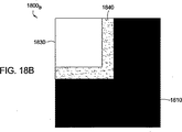
[0098]図18A,図18Bは、右下の凸状および凹状角検出用オーバーレイ1800A、1800Bをそれぞれ示す。図示されるように、凸状角検出用オーバーレイ1800Aは、3つの領域:全てのサブピクセルが黒(又はセット)でなければならない領域1810;少なくとも幾つかのサブピクセルが白でなければならない(換言すると、これらは全てが黒ではない)領域1820;全てのサブピクセルが白でなければならない領域1830;を有する。ピクセル・アレイの幾つかの部分が、これらの条件を満足するとき、表示された場所で角が検出される。
[0098] FIGS. 18A and 18B show lower right convex and concave
[0099]例えば、右下の凸状角検出用オーバーレイ1800Aに対し、識別された角は、幾つかの白い領域1820と白い領域1830との間の右下境界点を含むピクセル内にある。幾つかの白い領域1820が、黒と白の一定の組合せであることを要求すること、或いは、全てが黒であることを少なくとも許容しないことにより、複数の角が検出されることを妨げることができる(例えば、オーバーレイの要求は、別の方法で満足され、隣りのピクセルが角であることを表示する)。実例として、凸状角検出用オーバーレイ1800Aの黒い領域1810及び幾つかの白い領域1820により占有されたエリアは、1−1/4ピクセルだけ高く、1−1/4だけ広く測定する。図18Bに示されるように、凹状角検出用オーバーレイ1800Bは、凸状角検出用オーバーレイ1800Aと同一であるが、黒い領域1810と白い領域1830は、互換性があり、幾つかの白い領域1820は、幾つかの黒い領域1840により交換される。
[0099] For example, for the lower right convex
角検出用オーバーレイの適用
[0100]図19A−図19Dは、(図15のステップ1508のように)内部にある形状1911の角を検出する為に、ピクセル1910の3×3のアレイ1900に対して凸状角検出用オーバーレイの応用を示す。図示のように、アレイ1900のピクセル1910は、左上から始まり、0から9までラベルが付されている。一般に、角検出用オーバーレイ1800は、オーバーレイを画成するサブピクセル状態が満足されるまで、(例えば、X方向及びY方向において、1/4ピクセル・ステップ内で)アレイ内を「滑り」回される。以下に詳細に説明されるように、幾つかのハードウェアの実現において、オーバーレイは、実際には滑り回されないが、内部に提供された論理が3×3アレイ内で全ての角を同時に検出する。
Applying corner detection overlay
[0100] FIGS. 19A-19D show convex angle detection for a 3 × 3
[0101]図19Aは、ピクセル0内で形状1911の左上の凸状角を検出する為に、アレイ1900内部でオーバーレイ1800A-ULの「位置」を示す。図示のように、オーバーレイの黒い領域1810内部の全てのサブピクセルは、形状1911により完全にカバーされており、黒であるが、白い領域1830内部のサブピクセルは完全に形状1911の外側であり、白である。最後に、幾つかの白い領域1820内部のサブピクセルの幾つかは、形状1911によりカバーされているが、幾つかはカバーされておらず、黒と白のサブピクセルの混合になっている。そのため、オーバーレイにより課された状態の全ては、満足され、左上の凸状角がピクセル0内に配置されていることを表示する。しかし、注意すべき点は、オーバーレイを丁度僅かに下又は右に移動させることにより、幾つかの白い領域が全ての黒いサブピクセルを含ませるので、角は検出されず、角インジケータは、まだ、ピクセル0内で配置されるであろうということである。
[0101] FIG. 19A shows the “position” of overlay 1800A-UL within
[0102]同様に、凸状角用テンプレート1800A-UR、1800A-LR、1800A-LLは、図19B−Dに示されるように、それぞれ、ピクセル2,8,6内で、形状1911の残りの凸状角を検出する為に適用可能である。形状1911は、凹状角を持たないが、内部にある凹状角を検出する為に、同様の方法で、ピクセル・アレイに凹状角用テンプレート1800Bが適用可能であることは確実に明らかである。
[0102] Similarly,
[0103]内部に含まれる全てのサブピクセルは全て黒か全て白でなければならないオーバーレイ1800の2つの「厳格な」領域1810及び1820があるが、幾つかの白い領域1820内に含まれるピクセルは、全て白か、或いは、幾つかが白で幾つかが黒でもよい。領域1830内の不明瞭性のため、1つ以上のピクセルは、ピクセル境界で形状が完全に整列するときのように、実際に同一の角を有するとして検出可能である。
[0103] Although there are two "strict"
[0104]この状況は、図20Aに示されているが、この図は、アレイ2000のピクセル1,2,4,5にある形状2011を示す。図示のように、形状2011の凸状角は、ピクセル3,4の間の境界にある。この場合、オーバーレイは、両方のピクセル3,4が凸状角を有することを見つけるであろう。例えば、図20Bに示された位置において、オーバーレイ1800A-LLを用いて、ピクセル4は、角を含むとして識別されるであろう。オーバーレイを左に14ピクセルだけシフトさせることにより、ピクセル3は、角を含むとして識別されるであろう。前述されたように、書き込まれるパターン内の望ましくない結合や間隙を形成する角補正の可能性のため、隣りのピクセル内で角を検出することは望ましくない。
[0104] This situation is illustrated in FIG. 20A, which shows a
[0105]そのような隣りの角は、幾つかのタイプの、後の検出角処理を実行することにより解決可能である。そのような処理の、一つの簡単な実施例は、角形ピクセル、凸状角に対する最外部のピクセル、或いは凹状角の最内部のピクセルとして片づけることである。図20B、図20Cに示された実施例における、このアプローチを適用すると、左下凸状角を含むとして識別された他のピクセル(ピクセル4)に対し、ピクセル3は最外部(最も「左」)である。
[0105] Such neighboring corners can be resolved by performing some type of later detection angle processing. One simple example of such processing is to clean up as a square pixel, an outermost pixel for a convex corner, or an innermost pixel for a concave corner. Applying this approach in the embodiment shown in FIGS. 20B and 20C,
角用タグ
[0106]角をピクセル内で単に検出することに加えて、その角があるピクセル内部で正確な位置を決定することも望ましい。そのような正確な位置は、角を含む形状により正確にどれがカバーされているかを決定する為にサンプリングされたサブピクセルを検査することにより決定可能であり、検出された角を補正するとき、より正確な投与量を見込むことができる(例えば、異なる補正投与量は、ピクセル内で角が配置される場所に依存して使用可能である)。幾つかの実施形態に対し、ピクセルは、領域とNビット数に分けられてもよく(以下、角用タグという。)、検出された角形ピクセルが存在する領域を識別する為に生成されてもよい。
Corner tag
[0106] In addition to simply detecting a corner within a pixel, it is also desirable to determine the exact location within a pixel at that corner. Such an exact position can be determined by examining the sampled sub-pixels to determine exactly what is covered by the shape including the corners, and when correcting the detected corners, More accurate doses can be anticipated (eg, different correction doses can be used depending on where the corners are located in the pixel). For some embodiments, the pixels may be divided into regions and N-bit numbers (hereinafter referred to as corner tags) or generated to identify regions where detected square pixels are present. Good.
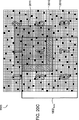
[0107]例えば、図21Aに示されるピクセル・マップ2100Aは、例示的に0−F(16進表記)までラベルが付された16個の領域2102Aに分けられてもよい。したがって、4ビットの角用タグは、角を含む16個の領域2102Aの一つを識別する為に使用可能である。図21Aも、ピクセル2110内の左上凸状角を検出する為に凸状角検出用オーバーレイ1800A-ULと、ピクセル2110の領域「B」内部に存在する角を表示する角用タグとを組み合わせたピクセル・マップ2100Aの使用を示す。以下に詳細に説明されるように、角用タグは、対応する領域に依存して異なるかもしれない補正係数を含む一組の角補正登録を読み出す為に使用可能である。換言すると、検出可能な角の異なるタイプの各々に対し、4ビットの角用タグは、16個の異なる組の補正係数の一つを読み出す為に使用可能であり、検出された角で放射投与量の正確な制御を許容する。
[0107] For example, the pixel map 2100A shown in Figure 21A, illustratively 0-F (16 hexadecimal notation) to be divided into the
[0108]16個の領域は、幾つかの用途では正確な角位置情報を提供可能であるが、それより劣る精度も必要であるかもしれない。そのため、図21Bに示されるように、ピクセル・マップ2100Bは、例示的に0−3でラベルが付けられるように、4つの領域2102Bに分けられてもよい。従って、2ビットの角用タグは、4つの領域2102Bの一つを識別し、対応する角補正登録の組を読み出す為に使用可能である。図21Bに示されたように、ピクセル・マップ2100Bは、ピクセル2110内で左上凸状角を検出する為に凸状角検出用オーバーレイ1800A-ULと、ピクセル2110の領域「3」内部に角が存在することを示す角用タグとの組合せで使用可能である。当業者は、領域の数と、所定用途の為に使用される補正登録の数が、システムリソース、コスト等に利用可能な特定用途のニーズのような数多くの考慮事項に基づき、選択可能である。
[0108] The 16 regions may provide accurate angular position information in some applications, but may require less accuracy. Thus, as shown in FIG. 21B, the
[0109]前述されたように、角用タグは、検出された角を含むピクセル内部の識別された領域に特有の補正係数を含む補正登録の組を読み出す為に使用可能である。幾つかの実施形態に対し、補正登録は、検出された角形ピクセルと数多くの囲むピクセルの放射投与量(グレースケール値)を調整する際に使用可能な、独立して調整可能な16ビットの補正係数を含んでもよい。図22に示されるように、異なるグループの補正登録2210は、検出可能な角の異なるタイプの各々に対し提供可能である。各グループは、各領域に対し異なる組の補正登録を含んでもよい。例えば、2ビット角用タグを仮定すると、各グループは、4組の補正登録22100-3を含んでもよい。
[0109] As described above, the corner tag can be used to read a set of correction registrations that include correction factors specific to the identified area within the pixel that contains the detected corner. For some embodiments, the correction registration is an independently adjustable 16-bit correction that can be used in adjusting the radiation dose (grayscale value) of the detected square pixel and a number of surrounding pixels. A coefficient may be included. As shown in FIG. 22, different groups of
[0110]例示的に、補正登録の各組は、検出された角形ピクセルのグレースケール値を調整する為の補正係数を含む一つの補正登録を含んでもよい。さらに、各組は、(凸状角の為に)外側に増加投与量を普及させる為に、囲んでいるピクセルのグレースケール値を調整する為に補正係数を含む3つの補正登録を含んでもよい。実際、角補正の登録は、角の型、生成されるタグに基づき、補正に重要性を付加するように働く。幾つかの実施形態に対し、最大4つのピクセル:角が配置された第1ピクセル;その角から45°の角の隣接ピクセル;左への(又は、発見された角に基づき右への)ピクセル;上方の(又は下方の)ピクセル;まで修正可能である角の型、角用タグにより、(例えば、対応する、ゼロに対する補正登録により)1つのピクセルは修正可能である。 [0110] Illustratively, each set of correction registrations may include one correction registration that includes a correction factor for adjusting the grayscale value of the detected square pixel. In addition, each set may include three correction registrations that include correction factors to adjust the grayscale values of the surrounding pixels in order to disseminate increasing doses outward (due to convex corners). . In fact, the registration of the corner correction works to add importance to the correction based on the corner type and the tag generated. For some embodiments, a maximum of four pixels: a first pixel with a corner placed; a neighboring pixel 45 ° from that corner; a pixel to the left (or to the right based on the found corner) One pixel can be modified (for example, by a corresponding correction registration for zero) with a corner type, corner tag that can be modified to the upper (or lower) pixel.
[0111]8つの角の型と(この例では)各角用タグに対し4つの登録があるので、全ての補正をカバーするには、ピクセル内部に4つの識別可能な角の位置がある場合には128個の16ビット登録が必要であり、16個の識別可能な角の位置がある場合(例えば、4ビットの角用タグが使用される場合)には512個の16ビット登録が必要である。このプログラム化可能性は、ユーザに、高度の精度で角補正投与量を投射させることを許容し、また、投射された投与量に任意の形(例えば、三角形)をとらせることを許容する。 [0111] Since there are four registrations for eight corner types and each corner tag (in this example), there are four identifiable corner positions within the pixel to cover all corrections. Requires 128 16-bit registrations, and if there are 16 identifiable corner positions (for example, when a 4-bit corner tag is used), 512 16-bit registrations are required It is. This programmability allows the user to project an angle corrected dose with a high degree of accuracy, and also allows the projected dose to take any shape (eg, a triangle).
[0112]これらの補正登録の使用は、図23に示されているが、この図は、中央のピクセルの領域「0」で検出された左上凸状角を有する描写された形状に対するピクセル・マップ2300を示す。図23に示された実施例は、2ビットの角用タグが使用されたことを仮定する。角用タグ「0」を使用すると、左上角に対する一組の補正の登録22100が読み出されてもよい。一つの登録(例示的に登録3)に含まれる補正係数は、角形ピクセルのグレースケール値を調整する為に使用されてもよいが、他の登録(例示的に登録0−2)に含まれた補正係数は、「補正された」囲んでいるピクセル2310cのグレースケール値を調整する為に使用されてもよい。幾つかの実施形態に対し、識別されたピクセルのグレースケール値を調整する為に、既存のサブピクセル・データを用いて、(そこからグレースケール値を生成する前に)4つの補正登録が論理的にOR処理されてもよい。あるいは、グレースケール値は、補正の登録に基づき、直接、修正されてもよい。
[0112] The use of these correction registrations is shown in FIG. 23, which shows a pixel map for the depicted shape with the upper left convex corner detected in the central pixel region “0”. 2300 is shown. The example shown in FIG. 23 assumes that a 2-bit corner tag has been used. When you use the corner for the tag "0", it may be read
エリア・ベースの角補正の為の典型的なハードウェア
[0113]図24は、サンプリングされたサブピクセル・データに基づき、エリア・ベースの角補正を実行する為に使用可能な典型的なハードウェアの実現例2400を示す。前述されたアプローチのように、ラスタライザー2404は、書き込まれるパターンを示すデータファイル2402を受け取り、そのパターンによりカバーされる数多くのサブピクセルの場所をサンプリングしてもよい。単純にグレースケール値(例えば、設定された、サンプリングされたサブピクセルの数を符号することにより生成された5ビット値)のピクセル・マップを生成して出力するというより、むしろ、ラスタライザー2404は、実際の(例えば、16ビットの)サブピクセル・データを出力してエリア・ベースの角補正を見込むことが可能である。図示のように、このサブピクセル・データは、角検出及び補正ユニット2410によりアクセスされてもよいフレーム・バッファ2406に保存されてもよい。
Typical hardware for area-based corner correction
[0113] FIG. 24 shows an
[0114]図示のように、角検出及び補正ユニット2410は、そのフレーム・バッファ2406からサブピクセル・データを受け取る角検出ユニット2418を含んでもよい。
図示のように、幾つかの実施形態において、角検出ユニットは、ピクセル(例えば、16ピクセル)の「フレーム」用サブピクセル・データを受け取り、前述されたように、同時に角検出用オーバーレイを内部のピクセル・アレイに適用して角形ピクセルを検出してもよい。幾つかの実施形態において、オーバーレイの検出領域は、1−1/4ピクセルの高さ、広さでもよい(例えば、白と幾つかの白い領域の凸状角用オーバーレイでもよい)ので、縁で、或いは、縁で、或いは「見える」フレームから離れる角を考慮に入れる為に、フレームの周りに境界ピクセルを含むことが必要になるかもしれない。角検出ユニット2418は、また、角を含む、検出された角形ピクセル内部に位置を識別する角用タグを生成してもよい。
[0114] As shown, the corner detection and
As shown, in some embodiments, the corner detection unit receives sub-pixel data for “frames” of pixels (eg, 16 pixels) and simultaneously includes a corner detection overlay as described above. It may be applied to a pixel array to detect square pixels. In some embodiments, the overlay detection area may be 1-1 / 4 pixels high and wide (eg, a convex corner overlay of white and several white areas), so at the edges. Alternatively, it may be necessary to include border pixels around the frame to take into account the corners or corners away from the “visible” frame.
[0115]角データ(例えば、識別された角、角の型、角用タグ)は、角補正を実行するように構成された角補正ユニット2420に送られてもよい。図25は、角補正ユニット2420により実行可能な典型的な操作2500を示す。ステップ2502において、角補正ユニット2420は、角データを受け取る。ステップ2504において、識別された各々を補正するように実行される操作(2506−2512)のループが挿入されている。
[0115] Corner data (eg, identified corners, corner types, corner tags) may be sent to a
[0116]ステップ2506,2508において、選択された角の内部で角の位置を識別する角用タグ、角の型が、それぞれ、取得される。ステップ2510において、角の型と角用タグの組合せに対して、補正値(例えば、角補正登録2210で保存されたもの)が読み出される。ステップ2512において、識別された角形ピクセルと隣接ピクセルのグレースケール値が、読み出された補正値を使用して調整される。前述されたように、幾つかの実施形態に対し、グレースケール値は、グレースケール変換処理(例えば、符号セットサブピクセル・ビット)中、補正されたグレースケール値を導くサブピクセル情報で補正値を論理OR処理することにより、調整可能である。いったん補正が、識別された角の各々に対し行われると、ステップ2514で、修正された(調整されたグレースケール値を備えた)ピクセル・マップを使用して、パターンが書き込まれる。
[0116] In
有効な階層構造のハードウェアの実現例
[0117]角補正及び検出ユニット2410の構成要素は、FPGAや汎用ASICのような適切なハードウェア構成要素の、あらゆる組合せを使用して実現可能である。しかし、エリア・ベース・アプローチを使用して処理可能な潜在的に大量のサブピクセルのため、そのようなハードウェア構成要素で必要なゲート数は、構成要素の制限を達成可能である。そのため、幾つかの実施形態に対し、角補正の機能性を実現する為に必要なゲート数を最小にするように努めつつ、幾つかのタイプの最適化を実行することが望ましい。
Realization of hardware with effective hierarchical structure
[0117] The components of the angle correction and
[0118]FPGA技術は、一般に、4つの入力と1つの出力を有する原始的素子から成る。この基本的なビルディングブロックの利点を取ることにより、有効なエリア・ベースの角検出用アルゴリズムの一実施形態は、サブピクセル・データに基づき異なる階層のデータオブジェクトを生成する為に異なる層の論理を使用し、階層構造的アプローチを使用するFPGAで実現可能である。図26の角検出ユニット2410において、そのような実現例が示されているが、図26には、(例えば、4つの入力/1つの出力プリミティブを使用する)第1の論理層2620が利用され、「クワド」(Quad)を生成する為に4つのサブピクセルの組を組み合わせるように利用されている。第2の論理層2622は、"Blocks"を生成する為に4つのクワドの組を組み合わせるように利用されているが、これらは、角信号を生成する為に第3の論理層2624により組み合わせてもよい。全体のゲート数を最小にする一方、サブサンプル・ピクセル・アレイ2602内の複数のピクセルに対し、並列に、前述された角検出用オーバーレイを適用するように努めつつ、論理層で使用されたプリミティブは、結合論理式を実現するように構成可能である。
[0118] FPGA technology generally consists of primitive elements with four inputs and one output. By taking advantage of this basic building block, one embodiment of an effective area-based corner detection algorithm uses different layers of logic to generate different layers of data objects based on subpixel data. And can be implemented in an FPGA using a hierarchical approach. Although such an implementation is shown in the
[0119]図27は、クワドQ0−Q7の組を生成する為に使用可能な隣接ピクセルに対し、それぞれ、奇数及び偶数の典型的なピクセル・マップ2600Oと2600Eを示す。
クワドを生成する為に使用される論理層2620は、実際、4つのサブピクセル入力の関数のような出力信号を生成する。クワドは、集合的に、角によりカバーされた、ピクセル・エリア又はピクセルの組を示す為に使用されるので、対応した論理層は、典型的に、サブピクセルの組の直接の合計ではない。むしろ、各クワドは、ピクセルの4/16を示し、(P1-P4とラベルが付けられた)4つの位置に分けられる。(クワドQ0の位置P3のような)サブサンプルを含まないクワドの位置が存在する場合、それは、対応する式において有効に考慮されない。一方、クワドの位置が(クワドQ0の位置P1のような)2つのサブサンプルを有する場合には、2つのサブサンプルは、共に、OR処理される。そのため、論理層2620は、クワドQ1−Q3に対し、以下の式を実現してもよい。
Q0 = (s0 | s1) & s2 & s3
Q1 = s4 & (s5 | s6) & s7
Q2 = s8 & s9 & s10 & s11
Q3 = s12 & s13 & s14 & s15
ここで、シンボル|と&は、論理OR処理及び論理AND処理関数をそれぞれ示し、サンプリングされたサブサンプルs0-s15は、奇数のマップ2700Aからである。同様の式が、偶数のピクセル・マップ2700Eからサンプリングされたサブピクセルを使用して、クワドQ4−Q7を生成する為に実現可能である。
[0119] FIG. 27 shows exemplary pixel maps 2600 O and 2600 E for odd and even numbers, respectively, for adjacent pixels that can be used to generate quad Q0-Q7 pairs.
The
Q0 = (s0 | s1) & s2 & s3
Q1 = s4 & (s5 | s6) & s7
Q2 = s8 & s9 & s10 & s11
Q3 = s12 & s13 & s14 & s15
Here, the symbol | and & represents a logical OR operation and a logical AND operation functions respectively, a sub-sample s0-s15 sampled is odd map 2700 A. Similar expressions, using the sampled sub-pixels from the even pixel map 2700 E, is feasible to generate the quads Q4-Q7.
[0120]図26に示されたように、第2論理層2622は、それぞれがブロックを生成する為に4つのクワドを組み合わせるプリミティブ要素の組を含む。そのため、それぞれのクワドが4/16のピクセル・エリアを示すので、ブロックは、ピクセルと同一寸法を有する。前述されたように、角検出用オーバーレイは、実際、ピクセル・アレイ内部で、1Aピクセル増分でスライドされてもよい。そのため、ピクセルの隣りに横たわるクワドを生成することが望ましい。例えば、図27を参照すると、Q3.25とラベルが付けられたクワドは、奇数ピクセル内に含まれた3つの部分(P2−P4)と隣りの偶数ピクセルに含まれた1つの部分(P1)内のサブサンプルから生成可能であり、Q3.5とラベルが付けられたクワドは、奇数ピクセルに含まれた2つの部分(P1−P2)内のサブサンプルから生成可能であり、Q3.75とラベルが付けられたクワドは、奇数ピクセルに含まれた1つの部分(P4)と、隣りの偶数ピクセルに含まれた3つの部分(P1−P3)内のサブサンプルから生成可能である。これらの「重複する」クワドは、ピクセル境界に整列しないブロックを生成する為に組み合わせることが可能である。
[0120] As shown in FIG. 26, the second
[0121]図28は、どのようにブロック2802が、図18Aに示された検出用オーバーレイ1800Aの要件を一組のピクセルが満足することを確実にすることにより、右下凸状角を検出するように組み合わされることが可能かを示す、典型的なダイアグラムを含む。実際、様々なブロック2802は、角検出用オーバーレイ1800Aと同一寸法を有するサブピクセル・データのアレイの為に生成可能であり、第3の論理層2624は、検出用オーバーレイの要件が満足されることを確実する為の論理を実現する。
[0121] FIG. 28 shows how
[0122]例えば、左上のダイアグラムに示され、B0とラベルが付された第1のブロックは、アレイの左上角に含まれる4つのクワドから集めることが可能であり、これは、オーバーレイ1800Aの「黒でなければならない」領域1810に対応する。したがって、左下の凸状角信号を生成する為に使用される論理層2624内の関数ユニットは、ブロックB0を生成する為に使用されるクワドに含まれるサンプリングされたサブピクセルの各々が全て1であることを確実にしなければならない。同様に、ブロックB1_,B2_,B3_は、白い領域1830をカバーすることに努めつつ、様々なクワドから集めることができる。これらのブロックは、全てのゼロのサブサンプルでクワドから生成されるべきである。これら3つのブロックは、全体的に白い領域1830をカバーしないので、右上のダイアグラムに示された追加のブロックB5_,B6_は、残りの部分をカバーするように構築可能である。(右上、左下、右下のダイアグラムに示された)ブロックB4,B7,B8は、幾つかの白い領域1820をカバーするように生成されてもよい。
[0122] For example, the first block shown in the upper left diagram and labeled B0 can be collected from the four quads contained in the upper left corner of the array, which is the " Corresponds to
[0123]前述されたブロックを使用することにより、第3の論理層2624は、以下の式を使用して、右下の凸状角を検出可能である。
CCVX-LR = BO & B1_ & B2_ & B3_ & (!B4 | !B7 | !B8) &B5_ & B6_
ここで、シンボル!は、論理否定関数を示す。そのため、この式は、以下のように解釈可能である。ブロックB0は、全てが1でなければならず、B1_,B2_,B3_,B5,B6は、全てがゼロでなければならず、ブロックB4,B7,B8内のサブピクセルの少なくとも一つは1でなければならない。同様に、ブロック・ベースの式は、他の角の型の為に角検出用オーバーレイを実現するように案出されてもよい。さらに、当業者は、幾つかのブロックの組合せが特定の角の型を検出する為に使用可能であり、使用される正確なブロックの組合せが任意に選択可能であることを認識するであろう。いずれの場合でも、ここで説明された階層構造のスキームの実現は、有効なハードウェアの利用を考慮に入れ、全体のゲート総数を減少させる。この方式と分かれた角検出、クワド、ブロックの使用は、また、(各クロックサイクルで実行される複数の操作を用いて)操作の有効なパイプラインを許容し、全体の検出及び補正操作が最大のクロックレートで行われること許容し、全体のパターン書き込み時間を減少させる。
[0123] By using the blocks described above, the
C CVX-LR = BO & B1_ & B2_ & B3_ & (! B4 |! B7 |! B8) & B5_ & B6_
Here, symbol! Indicates a logical negation function. Therefore, this equation can be interpreted as follows. Block B0 must be all 1, B1_, B2_, B3_, B5, B6 must all be zero, and at least one of the subpixels in blocks B4, B7, B8 is 1. There must be. Similarly, block-based equations may be devised to implement corner detection overlays for other corner types. Further, those skilled in the art will recognize that several block combinations can be used to detect a particular corner type, and the exact block combination used can be arbitrarily selected. . In any case, the implementation of the hierarchical scheme described herein takes into account effective hardware utilization and reduces the overall gate count. The use of corner detection, quads, and blocks separate from this method also allows for an effective pipeline of operations (using multiple operations performed in each clock cycle), maximizing overall detection and correction operations. It is allowed to be performed at a clock rate of 1, and the overall pattern writing time is reduced.
結論
[0124]ピクセルのグレースケール値(後のラスタライゼーション)をうまく処理することにより、ピクセル角における放射投与量またはピクセルの角付近の放射投与量は、境界の影響を補償する為に増減されてもよい。その結果、書き込まれるパターンの実際の角は、そのパターンを示すデータファイルのサイズやデータ転送時間を増加することなく、より密接に理想的な角のパターンに似るようになる。
Conclusion
[0124] By processing pixel grayscale values (later rasterization), the radiation dose at or near the pixel corner can be increased or decreased to compensate for the effects of the border. Good. As a result, the actual corner of the pattern to be written more closely resembles the ideal corner pattern without increasing the size of the data file representing that pattern and the data transfer time.
[0125]前述したことは、本発明の実施形態に向けられているが、他の更なる本発明の実施形態も、本発明の基本的範囲を逸脱することなく、案出可能であり、その範囲は添付された請求項により決定される。 [0125] Although the foregoing has been directed to embodiments of the present invention, other further embodiments of the present invention can be devised without departing from the basic scope of the present invention. The scope is determined by the appended claims.
1101…データファイル、1104…ラスタライザー、1106…フレーム・バッファ、1110…角検出及び補正ユニット、1112…当初グレースケール・バッファ、1114…ブーリアン型ピクセル・バッファ、1116…補正されたピクセル・バッファ、1118…角検出ユニット、1120…角補正ユニット 1101 ... Data file, 1104 ... Rasterizer, 1106 ... Frame buffer, 1110 ... Corner detection and correction unit, 1112 ... Initial grayscale buffer, 1114 ... Boolean pixel buffer, 1116 ... Corrected pixel buffer, 1118 ... Corner detection unit, 1120 ... Correct correction unit
Claims (15)
前記パターンの画像に対しデータファイルをラスタライズすることによりグレースケールのピクセル・マップを生成するステップであって、前記ピクセル・マップは、0から整数Nの間の対応グレースケール値を有するピクセル・アレイを備える、前記ステップと;
前記グレースケールのピクセル・マップ内の対応ピクセルのグレースケール値に依存して、0か1のブーリアン値を有するピクセル・アレイを備えるブーリアン型ピクセル・マップを生成するステップと;
角に対応するピクセル用テンプレートに、角型ピクセルに対応するピクセル及び囲んでいるピクセルを含む前記ブーリアン型マップ内のピクセル・アレイを比較することにより、前記グレースケールのピクセル・マップ内で角型ピクセルを検出するステップと;
角型ピクセルと、角型ピクセルに隣接するピクセルのうち少なくとも一つのグレースケール値を調整するステップと;
を備える、前記方法。In the method for adjusting the corner of the pattern written on the high sensitivity recording surface:
Generating a grayscale pixel map by rasterizing a data file for the pattern image, the pixel map comprising a pixel array having a corresponding grayscale value between 0 and an integer N; Comprising the steps;
Generating a Boolean pixel map comprising a pixel array having a Boolean value of 0 or 1, depending on the grayscale value of the corresponding pixel in the grayscale pixel map;
By comparing a pixel array in the grayscale pixel map by comparing a pixel array in the Boolean map including a pixel corresponding to the corner pixel and an enclosing pixel to a pixel template corresponding to the corner Detecting
Adjusting a grayscale value of at least one of the corner pixels and pixels adjacent to the corner pixels;
Said method.
当初のグレースケール・バッファ内の凸状角形ピクセルのグレースケール値と、第1補正係数との和を計算する工程と;
前記計算された和が最大グレースケール値以下である場合、前記凸状角形ピクセルに対応する前記補正バッファ内のピクセルのグレースケール値を、前記第1補正係数だけ増加する工程と;
を備える、請求項2に記載の方法。The steps for adjusting the grayscale value of at least one of the square pixel and the pixels adjacent to the square pixel are:
Calculating the sum of the gray scale value of the convex square pixel in the original gray scale buffer and the first correction factor;
If the calculated sum is less than or equal to a maximum grayscale value, increasing a grayscale value of a pixel in the correction buffer corresponding to the convex square pixel by the first correction factor;
The method of claim 2 comprising :
前記計算された和が前記最大のグレースケール値を超える場合、前記凸状角形ピクセルに対応するピクセルに隣接する前記補正バッファ内の1以上のピクセルのグレースケール値を増加するステップを更に備える、請求項3に記載の方法。The steps for adjusting the grayscale value of at least one of the square pixel and the pixels adjacent to the square pixel are:
The method further comprises increasing a grayscale value of one or more pixels in the correction buffer adjacent to a pixel corresponding to the convex square pixel if the calculated sum exceeds the maximum grayscale value. Item 4. The method according to Item 3 .
前記当初のグレースケール・バッファ内の凹状角のグレースケール値から、第2補正係数を減算することにより、差の値を計算する工程と;
計算された差が最小のグレースケール値以下である場合、前記補正バッファ内の前記凹状角に対応するピクセルのグレースケール値から、第2補正係数だけ減少させる工程と;
を備える、請求項3に記載の方法。The steps for adjusting the grayscale value of at least one of the square pixel and the pixels adjacent to the square pixel are:
Calculating a difference value by subtracting a second correction factor from the grayscale value of the concave corner in the original grayscale buffer;
If the calculated difference is less than or equal to the minimum gray scale values, from the gray scale value of the pixel corresponding to the concave corner in the correction buffer, and the second correction coefficient by reducing small let that process;
The method of claim 3 comprising :
前記計算された差が前記最小のグレースケール値未満である場合、前記凹状角に対応するピクセルに隣接する前記補正バッファ内の1以上のピクセルのグレースケール値を減少させる工程を更に備える、請求項6に記載の方法。The steps for adjusting the grayscale value of at least one of the square pixel and the pixels adjacent to the square pixel are:
The method further comprising reducing a grayscale value of one or more pixels in the correction buffer adjacent to a pixel corresponding to the concave corner if the calculated difference is less than the minimum grayscale value. 6. The method according to 6 .
前記パターンの画像に対しデータファイルをラスタライズすることによりグレースケールのピクセル・マップを生成するステップであって、前記ピクセル・マップは、対応する
グレースケール値を有するピクセル・アレイを備える、前記ステップと;
ブーリアン値を有するピクセル・アレイを備えるブーリアン型ピクセル・マップを生成するステップであって、1のブーリアン値は、0でないグレースケールを有するグレースケールのピクセル・マップ内の対応するピクセルを示し、0のブーリアン値は、0のグレースケール値を有するグレースケールのピクセル・マップ内の対応するピクセルを示す、前記ステップと;
各々が潜在的角形ピクセルにセンタリングされた前記ブーリアン型ピクセル・マップ内の一以上のピクセル・アレイを、凸状角および凹状角の両方に対応する複数のテンプレートと同時に比較することにより、前記グレースケールのピクセル・マップ内で角形ピクセルを検出するステップと;
検出された角形ピクセルと、検出された角形ピクセルに隣接するピクセルのうち少なくとも一つのグレースケール値を調整するステップと;
を備える、前記方法。In the method for adjusting the corner of the pattern written on the high sensitivity recording surface:
Generating a grayscale pixel map by rasterizing a data file for the image of the pattern, the pixel map comprising a pixel array having a corresponding grayscale value;
Generating a Boolean pixel map comprising a pixel array having a Boolean value, where a Boolean value of 1 indicates a corresponding pixel in a grayscale pixel map having a non-zero grayscale; The Boolean value indicates the corresponding pixel in the grayscale pixel map having a grayscale value of 0;
By comparing one or more pixel arrays in the Boolean pixel map, each centered on a potential square pixel, simultaneously with a plurality of templates corresponding to both convex and concave corners, the gray scale Detecting square pixels in the pixel map of;
Adjusting a grayscale value of at least one of the detected square pixels and pixels adjacent to the detected square pixels;
Said method.
前記パターンの画像に対するデータファイルからグレースケールのピクセル・マップを生成するように構成されたラスタライザーであって、前記グレースケール・マップは、対応するグレースケール値を有するピクセル・アレイを備える、前記ラスタライザーと;
前記グレースケールのピクセル・マップ内の対応するピクセルのグレースケール値に依存して、0か1のブーリアン値を有するピクセル・アレイを備えるブーリアン型ピクセル・マップを生成する為の論理回路と;
前記ブーリアン型ピクセル・マップ内のピクセル・アレイを、角に対応するピクセルの角用テンプレートと比較することにより、グレースケールのピクセル・マップ内で角形ピクセルを検出するように構成された角検出ユニットと;
角形ピクセルと、角形ピクセルに隣接するピクセルのうち少なくとも一つのグレースケールのピクセル・マップ内でグレースケール値を調整するように構成された角補正ユニットと;
を備える、前記システム。A system for writing a pattern on a resistive surface:
A rasterizer configured to generate a grayscale pixel map from a data file for the pattern image, the grayscale map comprising a pixel array having a corresponding grayscale value. With riser;
Logic for generating a Boolean pixel map comprising a pixel array having a Boolean value of 0 or 1, depending on the grayscale value of the corresponding pixel in the grayscale pixel map;
A corner detection unit configured to detect a square pixel in a grayscale pixel map by comparing the pixel array in the Boolean pixel map with a corner template for the pixel corresponding to the corner; ;
A corner correction unit configured to adjust a grayscale value in a pixel map of at least one of the pixels adjacent to the corner pixel and a grayscale pixel;
Comprising the system.
前記グレースケール・ピクセル・マップ内の凸状角形ピクセルのグレースケール値と第1補正係数の和を計算すること;
計算された和が最大のグレースケール値以下である場合、前記第1補正係数だけ前記凸状角形ピクセルのグレースケール値を増加し、他の場合には、前記最大量に前記凸状角形ピクセルのグレースケール値を設定し、計算された和の残分を1以上の隣接ピクセルに普及させること;
により、調整するように構成されている、請求項12に記載のシステム。The corner detection unit selects at least one of a square pixel and a pixel adjacent to the square pixel:
Calculating the sum of the gray scale value of the convex square pixel in the gray scale pixel map and the first correction factor;
If the calculated sum is less than or equal to the maximum grayscale value, the grayscale value of the convex square pixel is increased by the first correction factor; otherwise, the maximum amount of the convex square pixel is increased to the maximum amount. Set a grayscale value and spread the calculated sum residue to one or more neighboring pixels;
13. The system of claim 12 , wherein the system is configured to adjust.
前記グレースケール・ピクセル・マップ内の凹状角形ピクセルのグレースケール値から第2補正係数を減算することにより差を計算すること;
計算された差が最小のグレースケール値以下である場合、前記第2補正係数だけ前記凹状角型ピクセルのグレースケール値を減少させ、他の場合には、前記最小のグレースケール値に前記凹状角形ピクセルのグレースケール値を設定し、計算された差の残分だけ、1以上の隣接ピクセルのグレースケール値を減少させること;
により、調整するように構成されている、請求項13に記載のシステム。The corner detection unit selects at least one of a square pixel and a pixel adjacent to the square pixel:
Calculating a difference by subtracting a second correction factor from the grayscale value of the concave square pixel in the grayscale pixel map;
If the calculated difference is less than or equal to a minimum gray scale value, the gray scale value of the concave square pixel is decreased by the second correction factor; otherwise, the concave square shape is reduced to the minimum gray scale value. Set the grayscale value of the pixel and reduce the grayscale value of one or more neighboring pixels by the remainder of the calculated difference;
The system of claim 13 , wherein the system is configured to adjust.
Applications Claiming Priority (3)
| Application Number | Priority Date | Filing Date | Title |
|---|---|---|---|
| US10/882,959 US7529421B2 (en) | 2004-07-01 | 2004-07-01 | Optical proximity correction in raster scan printing based on corner matching templates |
| US10/882,959 | 2004-07-01 | ||
| PCT/US2005/023590 WO2006007570A1 (en) | 2004-07-01 | 2005-07-01 | Optical proximity correction in raster scan printing based on corner matching templates |
Publications (3)
| Publication Number | Publication Date |
|---|---|
| JP2008505364A JP2008505364A (en) | 2008-02-21 |
| JP2008505364A5 JP2008505364A5 (en) | 2008-08-14 |
| JP4753942B2 true JP4753942B2 (en) | 2011-08-24 |
Family
ID=35276133
Family Applications (1)
| Application Number | Title | Priority Date | Filing Date |
|---|---|---|---|
| JP2007519490A Expired - Fee Related JP4753942B2 (en) | 2004-07-01 | 2005-07-01 | Optical proximity effect correction in raster scanning printing based on corner fitting template |
Country Status (4)
| Country | Link |
|---|---|
| US (1) | US7529421B2 (en) |
| EP (1) | EP1766571A1 (en) |
| JP (1) | JP4753942B2 (en) |
| WO (1) | WO2006007570A1 (en) |
Cited By (1)
| Publication number | Priority date | Publication date | Assignee | Title |
|---|---|---|---|---|
| US9291902B2 (en) | 2010-03-05 | 2016-03-22 | Mycronic AB | Method and apparatus for merging multiple geometrical pixel images and generating a single modulator pixel image |
Families Citing this family (17)
| Publication number | Priority date | Publication date | Assignee | Title |
|---|---|---|---|---|
| US20030233630A1 (en) * | 2001-12-14 | 2003-12-18 | Torbjorn Sandstrom | Methods and systems for process control of corner feature embellishment |
| US7340713B2 (en) * | 2004-09-29 | 2008-03-04 | Synopsys, Inc. | Method and apparatus for determining a proximity correction using a visible area model |
| KR101407913B1 (en) * | 2005-09-26 | 2014-06-17 | 마이크로닉 마이데이터 아베 | Methods and systems for pattern generation based on multiple forms of design data |
| US8064682B2 (en) * | 2007-06-29 | 2011-11-22 | Intel Corporation | Defect analysis |
| JP4525722B2 (en) * | 2007-09-20 | 2010-08-18 | 株式会社デンソー | Weather information display device, program |
| US20100142838A1 (en) * | 2008-12-05 | 2010-06-10 | Micronic Laser Systems Ab | Gradient assisted image resampling in micro-lithographic printing |
| JP5438848B2 (en) * | 2010-02-23 | 2014-03-12 | エーエスエムエル ネザーランズ ビー.ブイ. | Lithographic apparatus and device manufacturing method |
| US11195213B2 (en) * | 2010-09-01 | 2021-12-07 | Apixio, Inc. | Method of optimizing patient-related outcomes |
| CN102135725B (en) * | 2011-03-20 | 2012-07-04 | 北京理工大学 | Method for acquiring total number of cut rectangles of PBOPC (Pixel-Based Optical Proximity Correction) optimal mask pattern |
| CN103208111B (en) | 2012-01-17 | 2015-10-07 | 富士通株式会社 | For method and apparatus and the image processing equipment of correction image angle point |
| US9047658B2 (en) * | 2013-11-05 | 2015-06-02 | United Microelectronics Corp. | Method of optical proximity correction |
| CN105549920B (en) * | 2015-12-10 | 2018-04-03 | 河北远东通信系统工程有限公司 | A kind of client based on Flex significantly map Method of printing |
| CN108073043A (en) * | 2016-11-07 | 2018-05-25 | 俞庆平 | A kind of optical uniformity compensation method of write-through screen printing system |
| EP3461116B1 (en) * | 2017-09-23 | 2024-04-17 | Heidelberg Polska Sp. z o.o. | A method and system for am screening and protecting printouts |
| KR20200072981A (en) | 2018-12-13 | 2020-06-23 | 삼성전자주식회사 | Design method for mask layout, OPC(Optical Proximity Correction) method, and methods for manufacturing mask using the OPC method |
| US10614340B1 (en) | 2019-09-23 | 2020-04-07 | Mujin, Inc. | Method and computing system for object identification |
| CN111681284A (en) * | 2020-06-09 | 2020-09-18 | 商汤集团有限公司 | Corner point detection method and device, electronic equipment and storage medium |
Citations (9)
| Publication number | Priority date | Publication date | Assignee | Title |
|---|---|---|---|---|
| JPH11201908A (en) * | 1998-01-16 | 1999-07-30 | Nec Corp | Device and method for visual inspecting and storage medium storing visual inspection program |
| WO2000041208A1 (en) * | 1999-01-06 | 2000-07-13 | Etec Systems, Inc. | An apparatus and method for controlling a beam shape |
| WO2000041207A1 (en) * | 1999-01-06 | 2000-07-13 | Etec Systems, Inc. | A method and apparatus that determines charged particle beam shape codes |
| WO2000041209A1 (en) * | 1999-01-06 | 2000-07-13 | Etec Systems, Inc. | Raster shaped beam, electron beam exposure strategy using a two dimensional multipixel flash field |
| JP2001283219A (en) * | 2000-02-17 | 2001-10-12 | Xerox Corp | Template fitting method |
| WO2003023488A1 (en) * | 2001-09-12 | 2003-03-20 | Micronic Laser Systems Ab | Graphics engine for high precision lithography |
| US20030107770A1 (en) * | 2001-07-11 | 2003-06-12 | Applied Materials, Inc. | Algorithm for adjusting edges of grayscale pixel-map images |
| WO2003052516A1 (en) * | 2001-12-14 | 2003-06-26 | Micronic Laser Systems Ab | Method and apparatus for patterning a workpiece |
| WO2004032000A1 (en) * | 2002-10-01 | 2004-04-15 | Micronic Laser Systems Ab | Methods and systems for process control of corner feature embellishment |
Family Cites Families (16)
| Publication number | Priority date | Publication date | Assignee | Title |
|---|---|---|---|---|
| US5553170A (en) | 1987-07-09 | 1996-09-03 | Ezel, Inc. | High speed image processing system having a preparation portion and a converting portion generating a processed image based on the preparation portion |
| US5329614A (en) | 1991-02-07 | 1994-07-12 | Unisys Corporation | Method and apparatus for enlarging gray scale images |
| US5363119A (en) | 1991-05-01 | 1994-11-08 | Atari Games Corporation | Scaling processor for raster images |
| DE69331547T2 (en) | 1992-11-02 | 2003-04-24 | Applied Materials Inc N D Ges | IMAGE FORMATTING FOR A PATTERN GENERATION DEVICE |
| EP0663645A3 (en) | 1994-01-13 | 1996-07-03 | Eastman Kodak Co | Bitmap registration by gradient descent. |
| US6023530A (en) | 1995-11-13 | 2000-02-08 | Applied Intelligent Systems, Inc. | Vector correlation system for automatically locating patterns in an image |
| US5751852A (en) | 1996-04-29 | 1998-05-12 | Xerox Corporation | Image structure map data structure for spatially indexing an imgage |
| US6038348A (en) | 1996-07-24 | 2000-03-14 | Oak Technology, Inc. | Pixel image enhancement system and method |
| DE19636949A1 (en) | 1996-09-11 | 1998-03-12 | Siemens Ag | Method for the detection of edges in an image signal |
| US5847959A (en) * | 1997-01-28 | 1998-12-08 | Etec Systems, Inc. | Method and apparatus for run-time correction of proximity effects in pattern generation |
| US6400838B2 (en) * | 1997-07-29 | 2002-06-04 | Kabushiki Kaisha Toshiba | Pattern inspection equipment, pattern inspection method, and storage medium storing pattern inspection program |
| US6061476A (en) | 1997-11-24 | 2000-05-09 | Cognex Corporation | Method and apparatus using image subtraction and dynamic thresholding |
| US6467076B1 (en) * | 1999-04-30 | 2002-10-15 | Nicolas Bailey Cobb | Method and apparatus for submicron IC design |
| US7167185B1 (en) * | 2002-03-22 | 2007-01-23 | Kla- Tencor Technologies Corporation | Visualization of photomask databases |
| US7043089B2 (en) * | 2003-02-27 | 2006-05-09 | Hewlett-Packard Development Company, L.P. | Overflow error diffusion |
| US7407252B2 (en) * | 2004-07-01 | 2008-08-05 | Applied Materials, Inc. | Area based optical proximity correction in raster scan printing |
-
2004
- 2004-07-01 US US10/882,959 patent/US7529421B2/en not_active Expired - Fee Related
-
2005
- 2005-07-01 WO PCT/US2005/023590 patent/WO2006007570A1/en active Application Filing
- 2005-07-01 JP JP2007519490A patent/JP4753942B2/en not_active Expired - Fee Related
- 2005-07-01 EP EP05769261A patent/EP1766571A1/en not_active Withdrawn
Patent Citations (10)
| Publication number | Priority date | Publication date | Assignee | Title |
|---|---|---|---|---|
| JPH11201908A (en) * | 1998-01-16 | 1999-07-30 | Nec Corp | Device and method for visual inspecting and storage medium storing visual inspection program |
| WO2000041208A1 (en) * | 1999-01-06 | 2000-07-13 | Etec Systems, Inc. | An apparatus and method for controlling a beam shape |
| WO2000041207A1 (en) * | 1999-01-06 | 2000-07-13 | Etec Systems, Inc. | A method and apparatus that determines charged particle beam shape codes |
| WO2000041209A1 (en) * | 1999-01-06 | 2000-07-13 | Etec Systems, Inc. | Raster shaped beam, electron beam exposure strategy using a two dimensional multipixel flash field |
| US6556702B1 (en) * | 1999-01-06 | 2003-04-29 | Applied Materials, Inc. | Method and apparatus that determines charged particle beam shape codes |
| JP2001283219A (en) * | 2000-02-17 | 2001-10-12 | Xerox Corp | Template fitting method |
| US20030107770A1 (en) * | 2001-07-11 | 2003-06-12 | Applied Materials, Inc. | Algorithm for adjusting edges of grayscale pixel-map images |
| WO2003023488A1 (en) * | 2001-09-12 | 2003-03-20 | Micronic Laser Systems Ab | Graphics engine for high precision lithography |
| WO2003052516A1 (en) * | 2001-12-14 | 2003-06-26 | Micronic Laser Systems Ab | Method and apparatus for patterning a workpiece |
| WO2004032000A1 (en) * | 2002-10-01 | 2004-04-15 | Micronic Laser Systems Ab | Methods and systems for process control of corner feature embellishment |
Cited By (1)
| Publication number | Priority date | Publication date | Assignee | Title |
|---|---|---|---|---|
| US9291902B2 (en) | 2010-03-05 | 2016-03-22 | Mycronic AB | Method and apparatus for merging multiple geometrical pixel images and generating a single modulator pixel image |
Also Published As
| Publication number | Publication date |
|---|---|
| US7529421B2 (en) | 2009-05-05 |
| WO2006007570A1 (en) | 2006-01-19 |
| EP1766571A1 (en) | 2007-03-28 |
| US20060002603A1 (en) | 2006-01-05 |
| JP2008505364A (en) | 2008-02-21 |
Similar Documents
| Publication | Publication Date | Title |
|---|---|---|
| JP4753941B2 (en) | Area-based optical proximity correction in raster scanning printing | |
| JP4753942B2 (en) | Optical proximity effect correction in raster scanning printing based on corner fitting template | |
| US7930653B2 (en) | Triangulating design data and encoding design intent for microlithographic printing | |
| US7010764B2 (en) | Effective proximity effect correction methodology | |
| US7106490B2 (en) | Methods and systems for improved boundary contrast | |
| US7209584B2 (en) | Pattern inspection apparatus | |
| JP2984633B2 (en) | Reference image creation method and pattern inspection device | |
| JPH11304453A (en) | Method for multi-gradation rounding-off correcting process and pattern inspection device | |
| US7328425B2 (en) | Method and device for correcting SLM stamp image imperfections | |
| US20080205743A1 (en) | Mask defect analysis | |
| KR20200022741A (en) | Method of manufacturing semiconductor device, method of extreme ultraviolet ray exposure and Method of optical proximity correction | |
| CN102193308B (en) | Microlithography masks including image reversal assist features, microlithography systems including such masks, and methods of forming such masks | |
| US7420710B2 (en) | Optical proximity correction in raster scan printing based on grayscale manipulation of the bitmap | |
| JP4266217B2 (en) | Pattern inspection apparatus, pattern inspection method, and program | |
| CN1688914A (en) | Methods and systems for improved boundary contrast | |
| JP3146542B2 (en) | Mask manufacturing method and mask manufacturing system | |
| JP3128876B2 (en) | Pattern creation method and pattern creation system | |
| JPH11271957A (en) | Mask, and method and device for manufacturing mask | |
| JP2012053286A (en) | Photomask, apparatus and method for manufacturing semiconductor device using the same, and method for arranging photomask pattern |
Legal Events
| Date | Code | Title | Description |
|---|---|---|---|
| A521 | Request for written amendment filed |
Free format text: JAPANESE INTERMEDIATE CODE: A523 Effective date: 20080626 |
|
| A621 | Written request for application examination |
Free format text: JAPANESE INTERMEDIATE CODE: A621 Effective date: 20080626 |
|
| RD03 | Notification of appointment of power of attorney |
Free format text: JAPANESE INTERMEDIATE CODE: A7423 Effective date: 20101130 |
|
| RD04 | Notification of resignation of power of attorney |
Free format text: JAPANESE INTERMEDIATE CODE: A7424 Effective date: 20101210 |
|
| A01 | Written decision to grant a patent or to grant a registration (utility model) |
Free format text: JAPANESE INTERMEDIATE CODE: A01 Effective date: 20110426 |
|
| A61 | First payment of annual fees (during grant procedure) |
Free format text: JAPANESE INTERMEDIATE CODE: A61 Effective date: 20110524 |
|
| FPAY | Renewal fee payment (event date is renewal date of database) |
Free format text: PAYMENT UNTIL: 20140603 Year of fee payment: 3 |
|
| R150 | Certificate of patent or registration of utility model |
Free format text: JAPANESE INTERMEDIATE CODE: R150 |
|
| LAPS | Cancellation because of no payment of annual fees |