JP4751045B2 - Magnetic resonance imaging system - Google Patents
Magnetic resonance imaging system Download PDFInfo
- Publication number
- JP4751045B2 JP4751045B2 JP2004282435A JP2004282435A JP4751045B2 JP 4751045 B2 JP4751045 B2 JP 4751045B2 JP 2004282435 A JP2004282435 A JP 2004282435A JP 2004282435 A JP2004282435 A JP 2004282435A JP 4751045 B2 JP4751045 B2 JP 4751045B2
- Authority
- JP
- Japan
- Prior art keywords
- subject
- magnetic resonance
- coil
- magnetic field
- moving
- Prior art date
- Legal status (The legal status is an assumption and is not a legal conclusion. Google has not performed a legal analysis and makes no representation as to the accuracy of the status listed.)
- Expired - Fee Related
Links
Images


Description
本発明は、磁気共鳴現象を利用して磁気共鳴画像を生成する磁気共鳴イメージング(Magnetic Resonance Imaging:MRI)装置に関する。 The present invention relates to a magnetic resonance imaging (MRI) apparatus that generates a magnetic resonance image using a magnetic resonance phenomenon.
磁気共鳴イメージング装置は、固有の磁気モーメントを持つ核の集団が一様な静磁場中に置かれたときに、特定の周波数で回転する高周波磁場のエネルギーを共鳴的に吸収する現象を利用して、物質の化学的および物理的な微視的情報を映像化し、あるいは化学シフトスペクトラムを観測する装置である。 A magnetic resonance imaging apparatus utilizes a phenomenon in which energy of a high-frequency magnetic field rotating at a specific frequency is resonantly absorbed when a group of nuclei having a specific magnetic moment is placed in a uniform static magnetic field. It is a device that visualizes chemical and physical microscopic information of a substance or observes a chemical shift spectrum.
この磁気共鳴イメージング装置による診断画像の撮影は、例えば次のようにして実行される。すなわち、磁石により形成される静磁場と傾斜磁場コイルにより形成される傾斜磁場とからなる合成磁場の中に、被検体を配置する。この様にセッティングされた被検体に対して、磁気共鳴現象を発生させるための所定周波数の高周波を印加する。印加された高周波により、被検体において磁気共鳴信号が発生し、これを受信用高周波コイルにより受信し画像化する。 Imaging of a diagnostic image by this magnetic resonance imaging apparatus is executed as follows, for example. That is, the subject is placed in a synthetic magnetic field composed of a static magnetic field formed by a magnet and a gradient magnetic field formed by a gradient magnetic field coil. A high frequency of a predetermined frequency for generating a magnetic resonance phenomenon is applied to the subject set in this way. The applied high frequency generates a magnetic resonance signal in the subject, which is received by the receiving high frequency coil and imaged.
このようなMRI装置で、撮像範囲を広くする技術として、特許文献1および特許文献2が知られている。
特許文献1に開示されるMRI装置は、上下に分割されたコイルを予め架台内の撮像領域に固定しておき、その上下のコイルの間を被検者が移動しながら広い領域の撮像を可能にする。 The MRI apparatus disclosed in Patent Document 1 fixes a vertically divided coil to an imaging area in a gantry in advance, and enables imaging of a wide area while a subject moves between the upper and lower coils. To.
特許文献2に開示されるMRI装置は、コイルを上下に固定するための手段として、既存の寝台の上にコイルを保持するためのテーブルを置く。このテーブルの上に可動式の第2の寝台を置き、被検者はこの第2の寝台に乗ってすべるようにして架台内に送り込まれる。
The MRI apparatus disclosed in
特許文献3には、全身用高周波コイルと移動可能なサーフェスコイルとを備えるMRI装置が開示されている。
しかしながら特許文献1および特許文献2の技術では、いずれのコイルも固定されているため、コイルと被験者との距離が大きくなってしまい、効率的に感度を高めることができない。
However, in the techniques of Patent Document 1 and
また特許文献3の技術では、サーフェスコイルを撮像部位に近接させた後に撮像を行うのであって、一度の撮像範囲は狭くなってしまう。
In the technique disclosed in
本発明はこのような事情を考慮してなされたものであり、その目的とするところは、局所用高周波コイルを用いた高画質かつ広範囲な撮像を、プローブを被検体に装着することなしに行えるようにすることにある。 The present invention has been made in consideration of such circumstances, and the purpose of the present invention is to perform high-quality and wide-range imaging using a local high-frequency coil without mounting the probe on the subject. There is in doing so.
以上の目的を達成するために第1の本発明は、架台内に静磁場を発生する静磁場発生手段と、前記静磁場内に配置された被検体に傾斜磁場を印加する傾斜磁場発生手段と、前記傾斜磁場が印加された被検体から磁気共鳴信号を受信する高周波コイルと、前記被検体を移動させる被検体移動手段と、前記被検体移動手段により前記被検体が第1の方向に移動される際に受信された前記磁気共鳴信号に基づいて前記被検体の外形を検出する制御部と、前記被検体移動手段により前記被検体が前記第1の方向とは逆の第2の方向に移動される際に、前記検出された外形に基づいて、前記高周波コイルを前記被検体に対して遠近方向に移動させるコイル移動手段と、前記受信された磁気共鳴信号に基づいて磁気共鳴画像を生成する画像生成手段とを備えて磁気共鳴イメージング装置を構成した。 In order to achieve the above object, the first aspect of the present invention comprises a static magnetic field generating means for generating a static magnetic field in a gantry, and a gradient magnetic field generating means for applying a gradient magnetic field to a subject arranged in the static magnetic field. A high-frequency coil that receives a magnetic resonance signal from the subject to which the gradient magnetic field is applied, a subject moving unit that moves the subject, and the subject moving unit moving the subject in the first direction. A control unit that detects the outer shape of the subject based on the magnetic resonance signal received when the subject is moved , and the subject is moved in a second direction opposite to the first direction by the subject moving means. And generating a magnetic resonance image based on the received magnetic resonance signal and a coil moving means for moving the high-frequency coil in the perspective direction with respect to the subject based on the detected outer shape. With image generation means And a magnetic resonance imaging apparatus Te.
前記目的を達成するために第2の本発明は、架台内に静磁場を発生する静磁場発生手段と、前記静磁場内に配置された被検体に傾斜磁場を印加する傾斜磁場発生手段と、前記傾斜磁場が印加された被検体から磁気共鳴信号を受信する高周波コイルと、前記被検体を移動させる被検体移動手段と、前記被検体移動手段により前記被検体が第1の方向に移動される際に受信された前記磁気共鳴信号に基づいて前記被検体の外形を検出する制御部と、前記被検体移動手段により前記被検体が前記第1の方向と同じ方向に移動される際に、前記検出された外形に基づいて、前記高周波コイルを移動させるコイル移動手段と、前記受信された磁気共鳴信号に基づいて磁気共鳴画像を生成する画像生成手段とを備えて磁気共鳴イメージング装置を構成した。 In order to achieve the above object, the second aspect of the present invention comprises a static magnetic field generating means for generating a static magnetic field in a gantry, a gradient magnetic field generating means for applying a gradient magnetic field to a subject arranged in the static magnetic field, A high-frequency coil that receives a magnetic resonance signal from the subject to which the gradient magnetic field is applied, a subject moving unit that moves the subject, and the subject moving unit moves the subject in a first direction. A control unit that detects an outer shape of the subject based on the magnetic resonance signal received at the time, and when the subject is moved in the same direction as the first direction by the subject moving means, based on the detected contour, the coil moving means for moving the high-frequency coil, a magnetic resonance imaging apparatus and an image generating means for generating a magnetic resonance image based on the previous Ki受 signal has been magnetic resonance signals Configured
前記目的を達成するために第3の本発明は、架台内に静磁場を発生する静磁場発生手段と、前記静磁場内に配置された被検体に傾斜磁場を印加する傾斜磁場発生手段と、前記傾斜磁場が印加された前記被検体から磁気共鳴信号を受信する高周波コイルと、前記被検体から前記磁気共鳴信号を受信するホールボディコイルと、前記ホールボディコイルで受信された前記磁気共鳴信号に基づいて前記被検体の外形を検出する制御部と、前記検出された外形に基づいて、前記高周波コイルを前記被検体に対して遠近方向に移動させるコイル移動手段と、前記受信された磁気共鳴信号に基づいて磁気共鳴画像を生成する画像生成手段とを備えて磁気共鳴イメージング装置を構成した。 In order to achieve the above object, the third aspect of the present invention comprises a static magnetic field generating means for generating a static magnetic field in a gantry, a gradient magnetic field generating means for applying a gradient magnetic field to a subject arranged in the static magnetic field, A high frequency coil that receives a magnetic resonance signal from the subject to which the gradient magnetic field is applied, a hall body coil that receives the magnetic resonance signal from the subject , and the magnetic resonance signal received by the hall body coil. A control unit for detecting an outer shape of the subject based on the coil, a coil moving means for moving the high-frequency coil in a perspective direction with respect to the subject based on the detected outer shape, and the received magnetic resonance signal And an image generating means for generating a magnetic resonance image on the basis of the magnetic resonance imaging apparatus.
本発明によれば、局所用高周波コイルを用いた高画質かつ広範囲な撮像を、プローブを被検体に装着することなしに行える。 According to the present invention, high-quality and wide-range imaging using a local high-frequency coil can be performed without attaching a probe to a subject.
以下、図面を参照して本発明の実施形態につき説明する。
(第1の実施形態)
図1は第1の実施形態に係るMRI装置の構成を示す図である。図1に示すMRI装置は、静磁場磁石1、傾斜磁場コイル2、傾斜磁場電源3、高周波コイル4、送信部5、局所用プローブ6、位置調整機構7、受信部8、寝台制御部9および計算機システム10を具備する。
Hereinafter, embodiments of the present invention will be described with reference to the drawings.
(First embodiment)
FIG. 1 is a diagram showing the configuration of the MRI apparatus according to the first embodiment. The MRI apparatus shown in FIG. 1 includes a static magnetic field magnet 1, a gradient
静磁場磁石1は、中空の円筒形をなし、内部の空間に一様な静磁場を発生する。この静磁場磁石1としては、例えば永久磁石、超伝導磁石等が使用される。 The static magnetic field magnet 1 has a hollow cylindrical shape and generates a uniform static magnetic field in an internal space. As the static magnetic field magnet 1, for example, a permanent magnet, a superconducting magnet or the like is used.
傾斜磁場コイル2は、中空の円筒形をなし、静磁場磁石1の内側に配置される。傾斜磁場コイル2は、互いに直交するX,Y,Zの各軸に対応する3つのコイルが組み合わされている。傾斜磁場コイル2は、上記の3つのコイルが傾斜磁場電源3から個別に電流供給を受けて、磁場強度がX,Y,Zの各軸に沿って傾斜する傾斜磁場を発生する。なお、Z軸方向は、静磁場と同方向とする。X,Y,Z各軸の傾斜磁場は、スライス選択用傾斜磁場Gs、位相エンコード用傾斜磁場Geおよびリードアウト用傾斜磁場Grにそれぞれ対応される。スライス選択用傾斜磁場Gsは、任意に撮影断面を決めるために利用される。位相エンコード用傾斜磁場Geは、空間的位置に応じて磁気共鳴信号の位相をエンコードするために利用される。リードアウト用傾斜磁場Grは、空間的位置に応じて磁気共鳴信号の周波数をエンコードするために利用される。
The gradient
高周波コイル4は、中空の円筒形をなし、傾斜磁場コイル2の内側に配置される。この高周波コイル4の内側に、寝台Cに載置された被検体Pが挿入される。高周波コイル4は、送信部5から高周波パルスの供給を受けて、高周波磁場を発生する。また高周波コイル4は、上記の高周波磁場の影響により被検体から放射される磁気共鳴信号を受信する。高周波コイル4は、被検体Pが容易に通過できるような内径を有しおり、このために全身用RFプローブとして機能する。
The
送信部5は、発振部、位相選択部、周波数変換部、振幅変調部および高周波電力増幅部を有している。発振部は、静磁場中における対象原子核に固有の共鳴周波数の高周波信号を発生する。位相選択部は、上記高周波信号の位相を選択する。周波数変調部は、位相選択部から出力された高周波信号の周波数を変調する。振幅変調部は、周波数変調部から出力された高周波信号の振幅を例えばシンク関数に従って変調する。高周波電力増幅部は、振幅変調部から出力された高周波信号を増幅する。そしてこれらの各部の動作の結果として送信部5は、ラーモア周波数に対応する高周波パルスを高周波コイル4に送信する。
The transmission unit 5 includes an oscillation unit, a phase selection unit, a frequency conversion unit, an amplitude modulation unit, and a high frequency power amplification unit. The oscillation unit generates a high-frequency signal having a resonance frequency unique to the target nucleus in the static magnetic field. The phase selection unit selects the phase of the high-frequency signal. The frequency modulation unit modulates the frequency of the high-frequency signal output from the phase selection unit. The amplitude modulation unit modulates the amplitude of the high-frequency signal output from the frequency modulation unit, for example, according to a sync function. The high frequency power amplification unit amplifies the high frequency signal output from the amplitude modulation unit. As a result of the operation of each of these units, the transmission unit 5 transmits a high frequency pulse corresponding to the Larmor frequency to the
局所用プローブ6は、高周波コイル4よりも小さな高周波コイルを内蔵する。局所用プローブ6は、高周波コイル4の内側に配置され、位置調整機構7により支持される。局所用プローブ6に内蔵された高周波コイルは、被検体Pから放射される磁気共鳴信号を受信する。
The
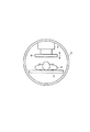
図2は高周波コイル4およびその内側を図1の左側から見た様子を示す図である。図1および図2に示すように、位置調整機構7は、高周波コイル4の内側に配置され、高周波コイル4の天井面に固定される。位置調整機構7は、高周波コイル4に直接固定されなくとも、種々の方法により高周波コイル4の内側に支持されていればよい。位置調整機構7は、図2中に矢印で示すように、局所用プローブ6を上下に移動させる。
FIG. 2 is a diagram showing a state in which the high-
受信部8は、選択器、前段増幅器、位相検波器およびアナログディジタル変換器を有している。選択器は、高周波コイル4および局所用プローブ6から出力される磁気共鳴信号を選択的に入力する。受信部8は、選択器から出力される磁気共鳴信号を増幅する。位相検波器は、前置増幅器から出力される磁気共鳴信号の位相を検波する。アナログディジタル変換器は、位相検波器から出力される信号をディジタル信号に変換する。
The receiving
寝台制御部9は、移動機構部および移動制御部を有する。移動機構部は、寝台Cを高周波コイル4の軸方向、すなわち図6における左右方向に往復移動させる。移動制御部は、後述する順方向移動および逆方向移動を行うように移動機構部を制御する。
The
計算機システム10は、インタフェース部10a、データ収集部10b、再構成部10c、記憶部10d、表示部10e、入力部10fおよび制御部10gを有している。
The
インタフェース部10aには、傾斜磁場電源3、送信部5、位置調整機構7、受信部8および寝台制御部9が接続される。インタフェース部10aは、これらの接続された各部と計算機システム10との間で授受される信号の入出力を行う。
A gradient magnetic
データ収集部10bは、受信部8から出力されるディジタル信号をインタフェース部10aを介して収集する。データ収集部10bは、収集したディジタル信号、すなわち磁気共鳴信号データを、記憶部10dに格納する。
The
再構成部10cは、記憶部10dに記憶された磁気共鳴信号データに対して、後処理、すなわちフーリエ変換等の再構成を実行し、被検体P内の所望核スピンのスペクトラムデータあるいは画像データを求める。
The
記憶部10dは、磁気共鳴信号データと、スペクトラムデータあるいは画像データとを、患者毎に記憶する。
The
表示部10eは、スペクトラムデータあるいは画像データ等の各種の情報を制御部10gの制御の下に表示する。表示部10eとしては、液晶表示器などの表示デバイスを利用可能である。
The
入力部10fは、オペレータからの各種指令や情報入力を受け付ける。入力部10fとしては、マウスやトラックボールなどのポインティングデバイス、モード切替スイッチ等の選択デバイス、あるいはキーボード等の入力デバイスを適宜に利用可能である。
The
制御部10gは、CPUやメモリ等を有しており、上記の各部を総括的に制御する。また制御部10gは、高周波コイル4から出力された磁気共鳴信号に応じて再構成された画像データに基づいて、被検体Pの外形を検出する。また制御部10gは、被検体Pを移動させることによる被検体Pの表面と局所用プローブ6との間隔の変化を補償して、局所用プローブ6を被検体Pの表面に近接した状態に維持するように、位置調整機構7を制御する。
The
次に以上のように構成されたMRI装置の動作について説明する。
被検体Pの全身を撮像しようとする場合、高周波コイル4の中から引き出した寝台Cに被検体Pを載置した状態とする。この上でオペレータは、入力部10fを操作して、全身撮影の開始を指令する。
Next, the operation of the MRI apparatus configured as described above will be described.
When the whole body of the subject P is to be imaged, the subject P is placed on the bed C pulled out from the
この指令は、入力部10fから制御部10gに伝えられる。上記の指令を受けて制御部10gは、図3のフローチャートに示されるような処理を開始する。
ステップSa1において制御部10gは、受信部8に対して「全身」を指定する。この指定を受けて受信部8は、高周波コイル4から出力される磁気共鳴信号を入力するようになる。続いてステップSa2において制御部10gは、寝台Cの順方向移動を開始するよう寝台制御部9へ指示する。この指示を受けて寝台制御部9は、寝台Cを順方向(例えば図1中の左側に向かう方向)に移動させる。寝台制御部9は、寝台Cを一定速度で移動させても良いし、1ピッチ毎に断続的に移動させても良い。そしてステップSa3において制御部10gは、外形検出を開始する。
This command is transmitted from the
In step Sa1, the
この外形検出は、被検体の外形を検出する処理である。具体的には、受信部8から出力される磁気共鳴信号データ、すなわち高周波コイル4で受信された磁気共鳴信号から受信部8で生成された磁気共鳴信号データに基づいて、被検体の断面形状を求め、その外形を検出する。外形の検出は、寝台Cの所定の位置毎に行われる。この外形検出を行いながら、ステップSa4において制御部10gは、順方向移動が完了するのを待ち受ける。
This outer shape detection is processing for detecting the outer shape of the subject. Specifically, the cross-sectional shape of the subject is determined based on the magnetic resonance signal data output from the receiving
予め定められた移動範囲の終端まで寝台Cが移動したならば、寝台制御部9は順方向移動を停止し、順方向移動が完了したことを制御部10gへ通知する。この通知を受けて制御部10gは、ステップSa4からステップSa5へと進む。そしてステップSa5において制御部10gは、外形検出を終了する。
If the bed C moves to the end of the predetermined moving range, the
続いてステップSa6において制御部10gは、受信部8に対して「局所」を指定する。この指定を受けて受信部8は、局所用プローブ6から出力される磁気共鳴信号を入力するようになる。続いてステップSa7において制御部10gは、寝台Cの逆方向移動を開始するよう寝台制御部9へ指示する。この指示を受けて寝台制御部9は、寝台Cを逆方向(例えば図1中の右側に向かう方向)に移動させる。そしてステップSa8において制御部10gは、局所用プローブ6の位置制御を開始する。
Subsequently, in step Sa6, the
位置制御は、被検体Pと局所用プローブ6とを干渉することなく近接させた状態を維持するように、局所用プローブ6の位置を調整する処理である。すなわち、被検体Pの移動にともなって局所用プローブ6に対向する被検体Pの部位が変化することにより、被検体Pと局所用プローブ6との間隔が変化するので、この間隔の変化を補償するように局所用プローブ6の位置を調整する。具体的には制御部10gは、寝台Cの移動に同期して、前述の外形検出により検出した被検体Pの外形を参照しながら位置調整機構7を駆動する。
The position control is a process of adjusting the position of the
図4は位置制御の下での局所用プローブ6の位置の変化の一例を示す図である。この図4に示すように、局所用プローブ6に対向している部位の高さに応じて、位置調整機構7の基部から局所用プローブ6までの間隔が、それぞれ異なるL1,L2,L3とされている。
FIG. 4 is a diagram illustrating an example of a change in the position of the
このように、寝台Cの逆方向移動および局所用プローブ6の位置制御が開始されたのちに、ステップSa9において制御部10gは、本撮像処理を開始する。この本撮像処理は、被検体Pの全体に関するスペクトラムデータあるいは画像データを求める処理である。この本撮像処理は、具体的には、受信部8から出力される磁気共鳴信号データ、すなわち局所用プローブ6で受信された磁気共鳴信号から受信部8で生成された磁気共鳴信号データに基づいて行われる。当該磁気共鳴信号データに基づき、被検体Pについての局所的なスペクトラムデータあるいは画像データを求める処理を、寝台Cの移動に同期して周期的に行う。そして、これらの局所的なスペクトラムデータあるいは画像データを集積することで、被検体Pの全体に関するスペクトラムデータあるいは画像データを求める。
As described above, after the backward movement of the bed C and the position control of the
このような本撮像処理を行いながら、ステップSa10において制御部10gは、被検体Pの全体の撮像が完了するのを待ち受ける。そして、被検体Pの全体の撮像が完了したならば、制御部10gはステップSa10からステップSa11へ進む。ステップSa11において制御部10gは、本撮像処理を停止するとともに、局部用プローブ6の位置制御を停止する。そしてこれをもって、制御部10gは図3に示す処理を終了する。
While performing this main imaging process, in step Sa10, the
以上のように第1の実施形態によれば、まず、全身用プローブである高周波コイル4を使用して被検体Pの外形を検出する。そして、この検出した外形を参照して局所用プローブ6を被検体Pに近接させた状態を維持しながら、局所用プローブ6を使用して被検体Pの全身を撮像する。この結果、局所用プローブ6の特徴を十分に生かして高品質に撮像することが可能である。また、局所用プローブ6を被検体Pに装着しないので、被検体Pに余計な負担を掛けることがない。また、寝台Cを往復移動させる間に外形検出と本撮像との双方を行うようにしているので、効率的に短時間で撮像を終えることが可能である。
As described above, according to the first embodiment, first, the outer shape of the subject P is detected using the high-
この第1の実施形態は、次のような種々の変形実施が可能である。
高周波コイル4を受信専用とし、送信用の高周波コイルを別途設けたクロスコイル方式を採用する構成であってもよい。
図5に示すように、局所用プローブ6に代えて局所用プローブ6a,6bを設けるとともに、位置調整機構7に代えて位置調整機構7a,7bを備えるようにして、局所用プローブ6a,6bの位置を個別に調整するようにしても良い。
以上では全身撮影を例に説明しているが、全身でなくとも被検体Pの移動をともなう広範囲な撮影にも本発明を適用できる。あるいは、被検体の移動なしでは撮像できない被検体の離れた複数部位を撮像するような場合にも本発明を適用できる。
The first embodiment can be variously modified as follows.
A configuration may be adopted in which a
As shown in FIG. 5, the
Although the whole body imaging has been described above as an example, the present invention can also be applied to a wide range imaging including the movement of the subject P even if not the whole body. Alternatively, the present invention can also be applied to a case where a plurality of parts of a subject that cannot be imaged without moving the subject are imaged .
(第2の実施形態)
図6は、第2の実施形態に係るMRI装置の構成を示すブロック図である。また、図7および図8は、図6中の受信コイルの移動機構の構成を示す図である。なお、説明の便宜上、図示のようにX,Y,Zの各軸方向を定義する。
(Second Embodiment)
FIG. 6 is a block diagram showing the configuration of the MRI apparatus according to the second embodiment. 7 and 8 are diagrams showing the configuration of the moving mechanism of the receiving coil in FIG. For convenience of explanation, the X, Y, and Z axis directions are defined as shown.
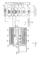
図6に示すように第2の実施形態のMRI装置は、架台21、寝台22、静磁場磁石23、傾斜磁場コイル24、高周波コイル25、受信コイル26a,26b,26c,26d、第1の移動機構27、第2の移動機構28、測距センサ29、センサ制御部30、傾斜磁場駆動部31、送信部32、移動機構制御部33、受信部34、データ収集部35、計算機36、コンソール37、ディスプレイ38およびシーケンスコントローラ39を具備する。
As shown in FIG. 6, the MRI apparatus of the second embodiment includes a
架台21は図6においてはYZ面で破断した断面を示している。架台21には、静磁場磁石23、傾斜磁場コイル24、高周波コイル25、受信コイル26a,26b,26c,26d、第1の移動機構27、第2の移動機構28および測距センサ29が設けられる。
The
寝台22は、被検体Pを架台21内に搬送する。
The
静磁場磁石23は、被検体Pに一様な静磁場を印加する。傾斜磁場コイル24は、被検体Pに対して傾斜磁場を印加する。高周波コイル25は、被検体Pに高周波磁場を印加する。受信コイル26a〜26dは、被検体Pから放射される磁気共鳴信号を受信する。
The static
第1の移動機構27は、受信コイル26aをY方向へ移動させる。第2の移動機構28は、受診コイル26aをX方向へ移動させる。測距センサ29は、被検体Pの体厚測定を行う。
The first moving
センサ制御部30は、被検体Pが架台21内に搬送されるのに同期して体厚測定を行うように測距センサ29を制御する。傾斜磁場駆動部31は、傾斜磁場コイル24を駆動する。送信部32は、高周波コイル25に高周波パルスを印加する。移動機構制御部33は、第1の移動機構27および第2の移動機構28の動作を制御する。受信部34は、受信コイル26a〜26dで受信された磁気共鳴信号を増幅および検波する。データ収集部35は、受信部34から出力される磁気共鳴信号をA/D変換して収集する。計算機36は、データ収集部35から出力された磁気共鳴信号に基づく画像再構成処理を行う。コンソール37は、計算機36に対して操作者により入力される情報を取り込む。ディスプレイ38は、計算機36の制御の下に各種の情報表示を行う。シーケンスコントローラ39は、傾斜磁場駆動部31、送信部32、移動機構制御部33、受信部34、データ収集部35および計算機36を制御する。
The
受信コイル26aが上側のコイル、受信コイル26b〜26dが下側のコイルとなっている。第2の実施形態では、複数の受信コイルが設けられる場合、受信コイル26aのように、少なくとも一つの受信コイルが上側にセットされて、残りが下側にセットされる。そして、上側のコイルと下側のコイルとがペアとなって信号を検出することで、広い撮像領域を得ることができる。下側に置くコイル数は、必要とされる撮像領域の広さに応じて定めればよい。撮像時、受信コイル26aは撮像領域の中央に配置される。受信コイル26aは、移動機構制御部33の制御の下に被検体Pの体厚に応じて上下動する。受信コイル26b〜26dは、後述する撮像領域指定法によりZ方向の撮像範囲が指定されると、それに応じて受信コイル26aの下に順次移動する。
The receiving
架台21の内部空間はボアと呼ばれる。架台21には、被検体Pを載置した寝台22の天板22aをボアに出し入れするための開口21aが設けられている。ボアの内壁上面部には、第2の移動機構28が設けられている。
The internal space of the
また、受信コイル26aの受信面(被検体Pに対向する面)の裏側に接続された後述する保持手段が、第1の移動機構27の一端に接続される。第1の移動機構27の他端が、第2の移動機構28に取り付けられている。
In addition, a holding means, which will be described later, connected to the back side of the receiving surface (the surface facing the subject P) of the receiving
図7に示すように、第1の移動機構27は、蛇腹機構27aを含む。第1の移動機構27は、コンプレッサも含む。コンプレッサが、架台21内に配置された流入管27bを介して蛇腹機構27aに空気を送り込んだり、あるいは蛇腹機構27aから空気を吸引したりすることにより、蛇腹機構27aを伸縮させる。蛇腹機構27aは、その伸縮方向をY方向に向けて配置される。なお、第1の移動機構27のY方向の移動変位と蛇腹機構27a内の圧力値との相関関係を示すデータをデータ収集部35に格納しておく。そして当該データをシーケンスコントローラ39が参照して、必要な変位に応じて蛇腹機構27a内の気圧を判定する。
As shown in FIG. 7, the first moving
第2の移動機構28はレール28aを備える。レール28aには、Z方向に溝28bが形成されている。矩形に形成された保持部材40が溝28bに係合することにより、受信コイル26aがレール28aにガイドされてZ方向に移動可能である。これは、ボア内での撮像位置を変更するための仕組みである。なお保持部材40は、第1の移動機構27によって受信コイル26aをY方向に移動させるときに溝28bとの係合が解除される構造を有している。
The
第2の移動機構28は、受信コイル26aを上記のようにZ方向に移動させるための動力源も備えている。この動力源としては、第1の移動機構27側にモータを設けるようにしてもよいし、第1の移動機構27から離れて配置したモータにより牽引紐を介して受信コイル26aを動かす機構を設けてもよい。
The
測距センサ29は、開口21aの上部に配置されている。測距センサ29は例えば、測距用のレーザまたは超音波を用いて天板22aや被検体Pの体表に反射させることによって測距するセンサを適用することが望ましい。
The
次に、以上のように構成された第2の実施形態のMRI装置の動作について説明する。撮像のためにはまず、寝台22に載置された被検体Pを架台21内に送り込む。これは、寝台22が天板22aを所定の速度でZ方向に移動することによる。このときに作業者は、被検体Pの撮像領域が測距センサ29の真下に位置したときに、作業者がコンソール37に設けられた測距開始ボタンを押下して開始信号をシーケンスコントローラ39に送信する。つぎに被検体Pの撮像領域が測距センサ29の真下を通過し終えたときに、作業者がコンソール37に設けられた測距終了ボタンを押下して終了信号をシーケンスコントローラ39に送信する。このため、測距開始ボタンおよび測距終了ボタンは、架台21の横に取り付けておくと都合がよい。
Next, the operation of the MRI apparatus of the second embodiment configured as described above will be described. For imaging, first, the subject P placed on the
開始信号がシーケンスコントローラ39に送信されたことを契機として、シーケンスコントローラ39は、センサ制御部30に対して体厚測定を開始するよう指示する。この後、終了信号がシーケンスコントローラ39に送信されたことを契機として、シーケンスコントローラ39は、センサ制御部30に対して体厚測定を終了するよう指示する。センサ制御部30は、上記のように開始が指示された後、上記のように終了が指示されるまでの間に、測距センサ29に被検体Pの体厚を計測させる。測距センサ29は、測定によって得られた情報を、センサ制御部30を介してシーケンスコントローラ39に送信する。
When the start signal is transmitted to the
そしてボア内に搬送された被検体Pに対して、静磁場磁石23により一様な静磁場を印加する。このとき、印加された静磁場の向きはZ方向とする。
A uniform static magnetic field is applied to the subject P conveyed in the bore by the static
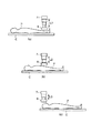
次に、移動機構制御部33は、第2の移動機構28によって、受信コイル26aを図8(a)に示す位置から、図8(b)に示すように静磁場磁石23の中央へ移動させる。この後、撮像領域の開始点に相当する被検体Pの部位が載置されている受信コイルが受信コイル26aの下方に位置するように寝台22を移動させる。ここでは、撮像領域の開始点が受信コイル26bの頭側端であり、終了点が受信コイル26dの足側端であるとして説明する。すなわちまず、受信コイル26aの下に受信コイル26bが位置するように寝台22を移動させる。
Next, the moving
この後に移動機構制御部33は、保持部材40と溝28bとの係合を解除する。移動機構制御部33はさらに、シーケンスコントローラ39から送信されたY方向の移動変位に関する情報に基づいて蛇腹機構27a内に空気を出し入れして、図8(c)に示すように受信コイル26aのY方向位置を調整し、受信コイル26aの受信面を被検体Pの体表に近接させる。
Thereafter, the movement
この後に傾斜磁場コイル24は、シーケンスコントローラ39の制御の下に傾斜磁場駆動部31によって駆動され、磁場強度がX,Y,Z方向に関して直線的にそれぞれ変化する傾斜磁場Gx,Gy,Gzを被検体Pに対して印加する。また、高周波コイル4は、シーケンスコントローラ39の制御の下に送信部32から高周波パルスが印加されることにより、被検体Pに高周波磁場を印加する。そして、受信コイル26aおよび受信コイル26bを利用して磁気共鳴信号を受信する。
Thereafter, the gradient
この後にシーケンスコントローラ39は、移動機構制御部33に対して、第1の移動機構27の移動変位に関する情報を送信して受信コイル26aの移動を指示する。
After that, the
引き続き寝台22の移動により、受信コイル26cを受信コイル26aの下方に位置させる。この状態で、上記と同様にして受信コイル26aおよび受信コイル26cを利用して磁気共鳴信号を受信する。さらに、受信コイル26dを受信コイル26aの下方に位置させる。この状態で、上記と同様にして受信コイル26aおよび受信コイル26dを利用して磁気共鳴信号を受信する。これにより、受信コイル26b〜26dの位置にわたる広い領域の磁気共鳴信号を取得できることになる。そして受信コイル26b〜26dのそれぞれの位置における被検体Pの体厚に応じて受信コイル26aが上下動するために、被検体Pに受信コイル26aが近接し、いずれの位置においても良好に磁気共鳴信号を得ることができる。
Subsequently, the receiving
受信コイル26a〜26dでそれぞれ受信された磁気共鳴信号は、受信部34で増幅および検波された後、A/D変換され、シーケンスコントローラ39の制御の下にデータ収集部35へと送られる。そして、データ収集部35では、シーケンスコントローラ39の制御の下に磁気共鳴信号を収集し、記憶する。データ収集部35は、シーケンスコントローラ39の制御の下に、記憶している磁気共鳴信号を計算機36に送る。計算機36は、シーケンスコントローラ39の制御の下に、データ収集部35から送られた磁気共鳴信号に基づく画像再構成を行う。計算機36により再構成された画像は、ディスプレイ38により表示される。
The magnetic resonance signals respectively received by the reception coils 26 a to 26 d are amplified and detected by the
この第2の実施形態は、次のような種々の変形実施が可能である。
以上に説明した具体例では、撮像したい領域の端部が受信コイル26b〜26dのコイル端と合っていたが、合わない場合もあり得る。このような場合には例えば、受信コイル26aに対して、受信コイル26bおよび受信コイル26cの両方の受信コイルに跨る撮像をすることになる場合には、受信コイル26a,26b,26cを利用して磁気共鳴信号を受信すればよい。受信コイル26b〜26dが予め寝台22に固定されているのであれば、撮像開始点および撮像終了点が指定された時点で、受信コイル26b〜26dのどの組合せで何回に分けて画像データを収集すべきか適宜計画すればよい。
The second embodiment can be variously modified as follows.
In the specific example described above, the end of the region to be imaged is aligned with the coil ends of the receiving coils 26b to 26d. In such a case, for example, when the
第2の移動機構28は省略することもできる。この場合には、受信コイル26aは、Z方向に対して固定される。そこで、開始信号が測距センサ29に送信されたことを契機に、寝台22上における被検体Pの撮像部位を特定する。そして、当該撮像部位が受信コイル26aの真下に来るように寝台22のZ方向の変位を制御すればよい。
The
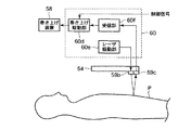
この第2の実施形態を変形して、図9に示すような構成としてもよい。すなわち、受信コイル26aを架台21内で移動させる機構を、L字型の支持具41を用いるものに変更する。支持具41の一端に受信コイル26aが取り付けられる。支持具41の他端を、架台21の外側に取り付けられる。そして架台21の側に設けた動力源により支持具41を移動させて、受信コイル26aを移動させる。
The second embodiment may be modified to have a configuration as shown in FIG. That is, the mechanism for moving the receiving
受信コイル26aを取り外し可能とし、プローブのような態様で検者が使用できるようにしてもよい。また、受信コイル26a,26b,26c,26dをそれぞれ、1つのユニットに複数のコイルを有するアレイコイルとしてもよい。
The receiving
寝台22に天板22aを上下動させる第3の移動機構を備えてもよい。被検体Pが小さいかまたは体厚が少ない場合に、受信コイル26aを被検体Pに対して大きく移動させる必要が生じる。これは、磁場磁石の好適な撮像領域である磁石中心から撮像領域を下げすぎることになり、感度が低下することになる。しかし、上述のような第3の移動機構を利用すれば、受信コイル26aの移動量を小さく抑えることができ、上記のような不具合を解消することができる。
You may provide the
受信コイル26b〜26dを利用せずに、受信コイル26aのみにより磁気共鳴信号の受信を行うことも可能である。
It is also possible to receive a magnetic resonance signal only by the receiving
測距センサ29は、受信コイル26aに取り付けるようにしても良い。この場合、まず被検体Pの撮影部位を受信コイル26aに対向させるように、天板22aを移動させる。この後、受信コイル26aから被検体Pまでの距離を測距センサ29で測定する。そしてこの測定結果に基づいて、受信コイル26aを上下動させれば良い。なおこの場合、測距センサ29の取り付け位置は、受信コイル26aの受信感度を低下させないように十分に考慮して定めるべきである。また測距センサ29は、アルミなどの電波シールド材によりシールドしておくことが望ましい。また測距センサ29により測距するタイミングは、撮像のためのパルスシーケンスが実行されていない期間、もしくは信号受信の期間外とすることが望ましい。
The
(第3の実施形態)
図10は第3の実施形態に係るMRI装置の構成を示す図である。なお、説明の便宜上、図示のようにX,Y,Xの各軸方向を定義する。
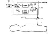
図10に示すように第3の実施形態のMRI装置は、架台51、寝台52、受信コイル53,54、ワイヤ55、滑車56,57、巻き上げ装置58、センサ59および制御部60を具備する。
(Third embodiment)
FIG. 10 is a diagram showing a configuration of an MRI apparatus according to the third embodiment. For convenience of explanation, the X, Y, and X axis directions are defined as shown.
As shown in FIG. 10, the MRI apparatus of the third embodiment includes a
架台51は図10においてはYZ面で破断した断面を示している。架台51には、静磁場磁石、傾斜磁場コイルおよび高周波コイルなどが設けられるが、これらの図示は省略している。第3の実施形態に係るMRI装置は、この他にも撮像を行うための周知の各種の要素を具備しているが、図10では特徴的な要素のみを図示し、他の要素は図示を省略している。
In FIG. 10, the
寝台52は、上天板52aおよび下天板52bからなる二重式の天板を備える。寝台52は、上天板52aをZ方向に移動させることにより、上天板52aに載置される被検体Pを架台51の内部空間に搬送する。上天板52aと下天板52bとの間には空隙を有し、この空隙内にRFコイル53が配置されている。全身スキャン時には、上天板52aが移動し、下天板52bは移動しない。すなわち、上天板52aに載置された被検体PがRFコイル53,54の間を搬送される。
The
RFコイル53は、マルチタイプの受信用コイルである。RFコイル53は、被検体Pから放射される磁気共鳴信号を受信する。
The
RFコイル54は、マルチタイプの受信用コイルである。RFコイル54は、架台51の内部空間に配置される。RFコイル54には、ワイヤ55の一端が接続される。ワイヤ55の他端は、滑車56,57によって架台51の外部に導かれ、巻き上げ装置58に接続されている。そしてRFコイル54は、ワイヤ55により吊り下げられた状態となっている。なお、滑車56,57は、支持部材により架台51に取り付けられている。
The
巻き上げ装置58は、ワイヤ55を巻き取ったり、あるいは繰り出したりすることにより、RFコイル54をY方向へ移動させる。
The winding
センサ59は、RFコイル54に固定されており、RFコイル54とともに移動する。センサ59は、RFコイル54と被検体Pの近接状態を検知する。
The
制御部60は、センサ59の出力を参照しながら、RFコイル54を被検体Pに近接させるように巻き上げ装置58を制御する。
The
図11は図10中の制御部60の詳細構成を示す図である。
制御部60は、超音波駆動部60a、マルチプレクサ60b、受信部60cおよび巻き上げ駆動部60dを具備する。この構成は、センサ59として超音波振動子59aを用いる場合のものである。
FIG. 11 is a diagram showing a detailed configuration of the
The
超音波駆動部60aは、超音波振動子59aに超音波を送信させるための送信信号を出力する。マルチプレクサ60bは、超音波駆動部60aが出力する送信信号を超音波振動子59aに出力する。マルチプレクサ60bは、超音波振動子59aが出力する信号を受信部60cへ出力する。受信部60cは、マルチプレクサ60bを介して入力される超音波振動子59aの出力信号に基づいて、RFコイル54と被検体Pとの距離が既定距離以下であるか否かを判定し、上記既定距離以下となった時に検出信号を巻き上げ駆動部60dへ出力する。巻き上げ駆動部60dは、上記の検出信号と、計算機システムから送られる制御信号とに基づいて巻き上げ装置58を駆動する。
The
次に以上のように構成されたMRI装置の動作について説明する。なお、再構成画像を得るための動作は第1の実施形態や第2の実施形態と同様で良いので、その説明は省略する。そしてここでは、RFコイル54の位置制御について説明する。
Next, the operation of the MRI apparatus configured as described above will be described. Note that the operation for obtaining a reconstructed image may be the same as that in the first embodiment or the second embodiment, and thus description thereof is omitted. Here, the position control of the
RFコイル53,54の受信範囲に相当する部位の撮像を行う毎に、上天板52aにより被検体Pを移動させることを繰り返す。
Every time imaging of a portion corresponding to the reception range of the RF coils 53 and 54 is performed, the movement of the subject P by the upper
さて、上天板52aを移動させる前には、巻き上げ駆動部60dに制御信号によって引き上げ指示が与えられる。これに応じて巻き上げ駆動部60dは、RFコイル54を十分に上昇させるべく、ワイヤ55を巻き取るように巻き上げ装置58を駆動する。このようにしてRFコイル54を被検体Pから引き離した後に、上天板52aが移動される。
Now, before the upper
上天板52aの移動が終了したならば、巻き上げ駆動部60dに制御信号によって近接指示が与えられる。これに応じて巻き上げ駆動部60dは、ワイヤ55を送り出すように巻き上げ装置58を駆動する。
When the movement of the upper
さて、巻き上げ装置58がワイヤを送り出すと、RFコイル54は降下し、被検体Pに近接して行く。このとき、超音波駆動部60aは、送信信号を間欠的に出力し、超音波振動子59aから超音波を送信させる。そして被検体Pにより反射されて超音波振動子59aにより受信された信号を受信部60cで受信する。受信部60cは、超音波振動子59aから超音波が送信されてから、その反射信号が受信されるまでの遅延時間が、既定距離に相当する既定時間以下になったか否かを判定する。なお既定時間は、予め計算により定めておいても良いし、例えばファントム等で測定して、キャリブレーションする様にしても良い。受信部60cは、上記の遅延時間が規定時間以下になったならば検出信号を出力する。巻き上げ駆動部60dは、受信部60cから検出信号が出力されると、巻き上げ装置58を停止させる。
Now, when the winding
すなわち制御部60は、RFコイル54が既定距離まで被検体Pに近接したならば、RFコイル54の移動を停止させる。そしてこの後に、RFコイル53,54により磁気共鳴信号を受信する。
That is, the
以上のように第3の実施形態によれば、被検体Pを移動させて撮像部位を変更しながら、それぞれの撮像部位に対する距離が既定距離となるようにRFコイル54が移動される。そしてRFコイル53,54により磁気共鳴信号を受信することで撮像が行われる。
As described above, according to the third embodiment, the
この結果、RFコイル54の特徴を十分に生かして高品質に撮像することが可能である。また、RFコイル54を被検体Pに装着しないので、被検体Pに余計な負担を掛けることがない。
As a result, it is possible to take high-quality images by making full use of the characteristics of the
なお、超音波振動子59aの取り付け位置は、RFコイル54の性能に影響しない様、各エレメント内に来ない様に配置することが望ましい。また、超音波振動子59aは、アルミ等の電波シールド材によりシールドしておくことが望ましい。超音波の送・受信に用いる周波数は、空気中での減衰が少なくなる様、比較的低い周波数を用いる。超音波の送・受信のタイミングは、MRIのパルスシーケンスが実行されていない期間とするか、もしくはパルスシーケンス実行中であっても信号受信の期間を外す様にする。
In addition, it is desirable to arrange the
この第3の実施形態は、次のような種々の変形実施が可能である。
図12は図10中の制御部60の別の構成を示す図である。なお、図11と同一部分には同一符号を付し、その詳細な説明は省略する。
図12に示す制御部60は、巻き上げ駆動部60d、レーザ駆動部60eおよび受信部60fを具備する。この構成は、センサ59をレーザ発振器59bおよび受光器59cにより構成する場合のものである。
The third embodiment can be variously modified as follows.
FIG. 12 is a diagram showing another configuration of the
The
レーザ駆動部60eは、レーザ発振器59bにレーザを発振させるための送信信号を出力する。受信部60fは、受信部60cは、受光器59cの出力信号に基づいて、RFコイル54と被検体Pとの距離が既定距離以下であるか否かを判定し、上記既定距離以下となった時に検出信号を巻き上げ駆動部60dへ出力する。
The
この図12に示す構成においては、被検体Pにレーザ光を照射した際に被検体Pから反射する光の強度に基づいて、RFコイル54が被検体Pに近接したことを検出する。
In the configuration shown in FIG. 12, it is detected that the
なお、被検体Pには、レーザ光の反射効率を高めるシートを貼付するか、塗料等を塗布しておくようにしても良い。レーザ光に代えて、赤外光などの他の光を利用しても良い。また、レーザ光は連続でなくても良く、MRIのデータ収集の妨げにならない時期に、断続的に送受する。 The subject P may be affixed with a sheet that enhances the reflection efficiency of laser light, or may be coated with a paint or the like. Instead of laser light, other light such as infrared light may be used. Further, the laser beam does not have to be continuous, and is transmitted and received intermittently at a time that does not hinder MRI data collection.
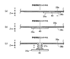
図13(a)は図10中の制御部60の別の構成を示す図である。なお、図11と同一部分には同一符号を付し、その詳細な説明は省略する。
図13(a)に示す制御部60は、巻き上げ駆動部60dおよび受信部60gを具備する。この構成は、センサ59を圧力センサ59dおよび圧力探査針59eにより構成する場合のものである。圧力探査針59eは、被検体Pに接触して圧力を圧力センサ59dに伝える。
FIG. 13A is a diagram showing another configuration of the
The
受信部60gは、圧力センサ59dの出力信号に基づいて、RFコイル54と被検体Pとの距離が既定距離以下であるか否かを判定し、上記既定距離以下となった時に検出信号を巻き上げ駆動部60dへ出力する。
The receiving unit 60g determines whether or not the distance between the
この図13(a)に示す構成においては、被検体Pに圧力探査針59eが接触した際に圧力センサ59dに伝わる圧力に基づいて、RFコイル54が被検体Pに近接したことを検出する。そして受信部60gは、圧力センサ59dにより一定値以上の圧力が感知されたときに検出信号を出力する。
In the configuration shown in FIG. 13A, the proximity of the
圧力センサ59dは、図13(b)に示すように、RFコイル54に取り付けた支持部材59fの先端に取り付け、圧力センサ59dが被検体Pに接触するようにしても良い。なお、圧力探査針59eは、面状としたり、複数針を用いる様にしても良い。また、圧力センサ59dを、複数箇所に設置する様にしても良い。圧力センサ59dは、面状(シート状)としたり、RFコイル54のエレメント部を避けるグリッド状等にしても良い。
As shown in FIG. 13B, the
図14は図10中の制御部60の別の構成を示す図である。なお、図11と同一部分には同一符号を付し、その詳細な説明は省略する。
図14に示す制御部60は、巻き上げ駆動部60dおよび判定部60hを具備する。この構成は、センサ59をマイクロスイッチ59gおよび探査針59hにより構成する場合のものである。探査針59hは、被検体Pに接触した際に変位してマイクロスイッチ59gをONする。
FIG. 14 is a diagram showing another configuration of the
The
判定部60hは、マイクロスイッチ59gの出力信号に基づいて、RFコイル54と被検体Pとの距離が既定距離以下であるか否かを判定し、上記既定距離以下となった時に検出信号を巻き上げ駆動部60dへ出力する。
The
この図14に示す構成においては、被検体Pに探査針59hが接触したことによってマイクロスイッチ59gがONしたことに基づいて、RFコイル54が被検体Pに近接したことを検出する。
In the configuration shown in FIG. 14, it is detected that the
なお、本発明は上記実施形態そのままに限定されるものではなく、実施段階ではその要旨を逸脱しない範囲で構成要素を変形して具体化できる。また、上記実施形態に開示されている複数の構成要素の適宜な組み合わせにより、種々の発明を形成できる。例えば、実施形態に示される全構成要素から幾つかの構成要素を削除してもよい。さらに、異なる実施形態にわたる構成要素を適宜組み合わせてもよい。 Note that the present invention is not limited to the above-described embodiment as it is, and can be embodied by modifying the constituent elements without departing from the scope of the invention in the implementation stage. In addition, various inventions can be formed by appropriately combining a plurality of components disclosed in the embodiment. For example, some components may be deleted from all the components shown in the embodiment. Furthermore, constituent elements over different embodiments may be appropriately combined.
1…静磁場磁石、2…傾斜磁場コイル、3…傾斜磁場電源、4,25…高周波コイル、5,32…送信部、6,6a,6b…局所用プローブ、7,7a,7b…位置調整機構、8…受信部、9…寝台制御部、10…計算機システム、21…架台、21a…開口、C,22,34…寝台、22a…天板、23…静磁場磁石、24…傾斜磁場コイル、26a,26b,26c,26d…受信コイル、27…第1の移動機構、28…第2の移動機構、29…測距センサ、30…センサ制御部、31…傾斜磁場駆動部、33…移動機構制御部、35…データ収集部、36…計算機、37…コンソール、38…ディスプレイ、39…シーケンスコントローラ、40…保持部材、41…支持具、51…架台、52…寝台、52b…下天板、52a…上天板、53,54…コイル、55…ワイヤ、56,57…滑車、58…巻き上げ装置、59…センサ、59a…超音波振動子、59b…レーザ発振器、59c…受光器、59d…圧力センサ、59e…圧力探査針、59f…支持部材、59g…マイクロスイッチ、59h…探査針、60…制御部、60a…超音波駆動部、60b…マルチプレクサ、60c,60f,60g…受信部、60d…巻き上げ駆動部、60e…レーザ駆動部、60h…判定部。
DESCRIPTION OF SYMBOLS 1 ... Static magnetic field magnet, 2 ... Gradient magnetic field coil, 3 ... Gradient magnetic field power supply, 4,25 ... High frequency coil, 5, 32 ... Transmitter, 6, 6a, 6b ... Local probe, 7, 7a, 7b ... Position adjustment Mechanism: 8: Receiving unit, 9: Bed control unit, 10: Computer system, 21: Base, 21a ... Opening, C, 22, 34 ... Bed, 22a ... Top plate, 23 ... Static magnetic field magnet, 24 ... Gradient magnetic field coil , 26a, 26b, 26c, 26d ... receiving coil, 27 ... first moving mechanism, 28 ... second moving mechanism, 29 ... distance measuring sensor, 30 ... sensor control unit, 31 ... gradient magnetic field driving unit, 33 ... moving Mechanism control unit, 35 ... data collection unit, 36 ... computer, 37 ... console, 38 ... display, 39 ... sequence controller, 40 ... holding member, 41 ... support, 51 ... stand, 52 ... bed, 52b ...
Claims (14)
前記静磁場内に配置された被検体に傾斜磁場を印加する傾斜磁場発生手段と、
前記傾斜磁場が印加された前記被検体から磁気共鳴信号を受信する高周波コイルと、
前記被検体を移動させる被検体移動手段と、
前記被検体移動手段により前記被検体が第1の方向に移動される際に受信された前記磁気共鳴信号に基づいて前記被検体の外形を検出する制御部と、
前記被検体移動手段により前記被検体が前記第1の方向とは逆の第2の方向に移動される際に、前記検出された外形に基づいて、前記高周波コイルを前記被検体に対して遠近方向に移動させるコイル移動手段と、
前記受信された磁気共鳴信号に基づいて磁気共鳴画像を生成する画像生成手段と、
を具備することを特徴とする磁気共鳴イメージング装置。 A static magnetic field generating means for generating a static magnetic field in the gantry,
A gradient magnetic field generating means for applying a gradient magnetic field to a subject arranged in the static magnetic field;
A high frequency coil for receiving a magnetic resonance signal from the subject to which the gradient magnetic field is applied;
Subject moving means for moving the subject;
A control unit for detecting an outer shape of the subject based on the magnetic resonance signal received when the subject is moved in the first direction by the subject moving means ;
When the subject is moved in the second direction opposite to the first direction by the subject moving means , the high-frequency coil is moved away from the subject based on the detected outer shape. Coil moving means for moving in the direction;
Image generating means for generating a magnetic resonance image based on the received magnetic resonance signal;
A magnetic resonance imaging apparatus comprising:
前記制御部は、前記ホールボディコイルで受信された前記磁気共鳴信号に基づいて、前記被検体の外形を検出することを特徴とする請求項1に記載の磁気共鳴イメージング装置。 A hall coil for receiving the magnetic resonance signal from the subject;
The magnetic resonance imaging apparatus according to claim 1 , wherein the control unit detects an outer shape of the subject based on the magnetic resonance signal received by the whole body coil.
前記制御部は、前記プリスキャン画像に基づいて前記被検体の外形を検出することを特徴とする請求項2に記載の磁気共鳴イメージング装置。 The image generation means generates a pre-scan image of the subject based on a magnetic resonance signal received by the whole body coil,
The magnetic resonance imaging apparatus according to claim 2 , wherein the control unit detects an outer shape of the subject based on the prescan image.
前記高周波コイルは前記検出された撮影条件下で前記磁気共鳴信号を受信することを特徴とする請求項1に記載の磁気共鳴イメージング装置。 Condition detection for detecting an imaging condition when the subject is moved in the second direction by the subject moving means when the subject is moved in the first direction by the subject moving means Further comprising means,
The magnetic resonance imaging apparatus according to claim 1 , wherein the high-frequency coil receives the magnetic resonance signal under the detected imaging condition.
前記静磁場内に配置された被検体に傾斜磁場を印加する傾斜磁場発生手段と、
前記傾斜磁場が印加された前記被検体から磁気共鳴信号を受信する高周波コイルと、
前記被検体を移動させる被検体移動手段と、
前記被検体移動手段により前記被検体が第1の方向に移動される際に受信された前記磁気共鳴信号に基づいて前記被検体の外形を検出する制御部と、
前記被検体移動手段により前記被検体が前記第1の方向と同じ方向に移動される際に、前記検出された外形に基づいて、前記高周波コイルを移動させるコイル移動手段と、
前記受信された磁気共鳴信号に基づいて磁気共鳴画像を生成する画像生成手段と、
を具備することを特徴とする磁気共鳴イメージング装置。 A static magnetic field generating means for generating a static magnetic field in the gantry,
A gradient magnetic field generating means for applying a gradient magnetic field to a subject arranged in the static magnetic field;
A high frequency coil for receiving a magnetic resonance signal from the subject to which the gradient magnetic field is applied;
Subject moving means for moving the subject;
Wherein a control unit for detecting a contour of the subject on the basis of the received magnetic resonance signal when the subject by the subject moving unit is moved in a first direction,
Coil moving means for moving the high-frequency coil based on the detected outer shape when the subject is moved in the same direction as the first direction by the subject moving means;
Image generating means for generating a magnetic resonance image based on the received magnetic resonance signal;
Magnetic resonance imaging apparatus characterized by comprising a.
前記静磁場内に配置された被検体に傾斜磁場を印加する傾斜磁場発生手段と、
前記傾斜磁場が印加された被検体から磁気共鳴信号を受信する高周波コイルと、
前記被検体から前記磁気共鳴信号を受信するホールボディコイルと、
前記ホールボディコイルで受信された前記磁気共鳴信号に基づいて前記被検体の外形を検出する制御部と、
前記検出された外形に基づいて、前記高周波コイルを前記被検体に対して遠近方向に移動させるコイル移動手段と、
前記コイル移動手段により移動される前記高周波コイルにより受信された前記磁気共鳴信号に基づいて磁気共鳴画像を生成する画像生成手段と、
を具備することを特徴とする磁気共鳴イメージング装置。 A static magnetic field generating means for generating a static magnetic field in the gantry,
A gradient magnetic field generating means for applying a gradient magnetic field to a subject arranged in the static magnetic field;
A high frequency coil for receiving a magnetic resonance signal from a subject to which the gradient magnetic field is applied;
A hall body coil for receiving the magnetic resonance signal from the subject;
A control unit for detecting an outer shape of the subject based on the magnetic resonance signal received by the whole body coil;
Coil moving means for moving the high-frequency coil in a perspective direction with respect to the subject based on the detected outer shape;
Image generating means for generating a magnetic resonance image based on the magnetic resonance signal received by the high-frequency coil moved by the coil moving means;
A magnetic resonance imaging apparatus comprising:
前記コイル移動手段は、前記被検体の移動に応じて、前記高周波コイルを移動させることを特徴とする請求項11に記載の磁気共鳴イメージング装置。 A subject moving means for moving the subject;
The magnetic resonance imaging apparatus according to claim 11 , wherein the coil moving unit moves the high-frequency coil according to the movement of the subject.
前記コイル移動手段は、前記被検体が前記第1の方向と同じ方向に移動される際に前記高周波コイルを移動させることを特徴とする請求項12に記載の磁気共鳴イメージング装置。 The control unit detects an outer shape of the subject based on the magnetic resonance signal received when the subject is moved in the first direction by the subject moving means;
The magnetic resonance imaging apparatus according to claim 12 , wherein the coil moving unit moves the high-frequency coil when the subject is moved in the same direction as the first direction.
Priority Applications (1)
| Application Number | Priority Date | Filing Date | Title |
|---|---|---|---|
| JP2004282435A JP4751045B2 (en) | 2003-12-04 | 2004-09-28 | Magnetic resonance imaging system |
Applications Claiming Priority (5)
| Application Number | Priority Date | Filing Date | Title |
|---|---|---|---|
| JP2003405779 | 2003-12-04 | ||
| JP2003405779 | 2003-12-04 | ||
| JP2004042863 | 2004-02-19 | ||
| JP2004042863 | 2004-02-19 | ||
| JP2004282435A JP4751045B2 (en) | 2003-12-04 | 2004-09-28 | Magnetic resonance imaging system |
Related Child Applications (1)
| Application Number | Title | Priority Date | Filing Date |
|---|---|---|---|
| JP2011083157A Division JP2011152438A (en) | 2003-12-04 | 2011-04-04 | Magnetic resonance imaging apparatus |
Publications (3)
| Publication Number | Publication Date |
|---|---|
| JP2005261924A JP2005261924A (en) | 2005-09-29 |
| JP2005261924A5 JP2005261924A5 (en) | 2007-11-08 |
| JP4751045B2 true JP4751045B2 (en) | 2011-08-17 |
Family
ID=35087049
Family Applications (1)
| Application Number | Title | Priority Date | Filing Date |
|---|---|---|---|
| JP2004282435A Expired - Fee Related JP4751045B2 (en) | 2003-12-04 | 2004-09-28 | Magnetic resonance imaging system |
Country Status (1)
| Country | Link |
|---|---|
| JP (1) | JP4751045B2 (en) |
Cited By (1)
| Publication number | Priority date | Publication date | Assignee | Title |
|---|---|---|---|---|
| KR101774394B1 (en) | 2015-12-11 | 2017-09-04 | 삼성전자주식회사 | Rf coil and magnetic resonance imaging device including the same |
Families Citing this family (11)
| Publication number | Priority date | Publication date | Assignee | Title |
|---|---|---|---|---|
| JP4576534B2 (en) * | 2006-03-28 | 2010-11-10 | 国立大学法人 筑波大学 | Magnetic resonance imaging apparatus and imaging method |
| JP5148173B2 (en) * | 2006-07-12 | 2013-02-20 | 株式会社東芝 | Magnetic resonance imaging system |
| JP5361163B2 (en) * | 2007-10-02 | 2013-12-04 | 株式会社東芝 | Magnetic resonance imaging system |
| KR101343037B1 (en) | 2011-11-10 | 2013-12-18 | 삼성전자 주식회사 | Wireless radio frequency coil for magnetic resonance imaging, power control method for the coil and magnetic resonance imaging machine using the coil |
| JP5362091B2 (en) * | 2012-10-22 | 2013-12-11 | 株式会社東芝 | Magnetic resonance imaging system |
| DE102014206011A1 (en) * | 2013-07-02 | 2015-01-08 | Siemens Aktiengesellschaft | A method for acquiring magnetic resonance data of a metal object-containing target area and a magnetic resonance device |
| JP6694867B2 (en) * | 2014-04-04 | 2020-05-20 | ピエルフランチェスコ パボーニ | Access gate or gantry with antenna assembly for treatment or diagnostic imaging |
| KR101806290B1 (en) * | 2016-01-18 | 2017-12-07 | 삼성전자주식회사 | Magnetic resonance imaging apparatus and method for detecting error of magnetic resonance imaging apparatus |
| JP7326011B2 (en) * | 2019-04-24 | 2023-08-15 | キヤノンメディカルシステムズ株式会社 | Magnetic resonance imaging system |
| CN210742484U (en) * | 2019-05-16 | 2020-06-12 | 佳能医疗系统株式会社 | MRI apparatus and RF coil unit for MRI apparatus |
| CN115754856B (en) * | 2022-12-12 | 2023-06-16 | 齐齐哈尔一脉阳光医学影像诊断中心有限公司 | Coil positioning device convenient to move in magnetic resonance |
Family Cites Families (8)
| Publication number | Priority date | Publication date | Assignee | Title |
|---|---|---|---|---|
| JPS62299247A (en) * | 1986-06-20 | 1987-12-26 | 株式会社日立製作所 | Surface coil unit for mri apparatus |
| US5085219A (en) * | 1987-10-30 | 1992-02-04 | The Regents Of The University Of California | Adjustable holders for magnetic reasonance imaging rf surface coil |
| JPH05123310A (en) * | 1991-10-31 | 1993-05-21 | Shimadzu Corp | Mri device bed |
| JPH07143974A (en) * | 1993-11-22 | 1995-06-06 | Shimadzu Corp | Magnetic resonance laminagraph |
| JPH10192273A (en) * | 1997-01-17 | 1998-07-28 | Canon Inc | Device and method for radiography |
| JP4024947B2 (en) * | 1998-10-01 | 2007-12-19 | 株式会社東芝 | RF coil of magnetic resonance imaging apparatus |
| JP2001095777A (en) * | 1999-10-01 | 2001-04-10 | Toshiba Corp | Nuclear magnetic resonance imaging apparatus |
| JP2001340332A (en) * | 2000-06-05 | 2001-12-11 | Hitachi Medical Corp | Radiodiagnosing device |
-
2004
- 2004-09-28 JP JP2004282435A patent/JP4751045B2/en not_active Expired - Fee Related
Cited By (2)
| Publication number | Priority date | Publication date | Assignee | Title |
|---|---|---|---|---|
| KR101774394B1 (en) | 2015-12-11 | 2017-09-04 | 삼성전자주식회사 | Rf coil and magnetic resonance imaging device including the same |
| US10184999B2 (en) | 2015-12-11 | 2019-01-22 | Samsung Electronics Co., Ltd. | RF coil and magnetic resonance imaging device including the RF coil |
Also Published As
| Publication number | Publication date |
|---|---|
| JP2005261924A (en) | 2005-09-29 |
Similar Documents
| Publication | Publication Date | Title |
|---|---|---|
| JP2011152438A (en) | Magnetic resonance imaging apparatus | |
| JP4751045B2 (en) | Magnetic resonance imaging system | |
| JP4854448B2 (en) | MRI apparatus and RF coil unit for MRI apparatus | |
| US6400157B1 (en) | MRI methods and systems | |
| JP2002530172A (en) | MR imaging system with defined MR geometry control | |
| JP6584767B2 (en) | Magnetic resonance imaging system | |
| RU2536113C2 (en) | Magnetic resonance elastography | |
| JP2018533410A (en) | Magnetic resonance examination system having user interface | |
| JPH10179551A (en) | Method to detect position of at least one local antenna | |
| JP6162131B2 (en) | Magnetic resonance imaging apparatus and magnetic resonance imaging method | |
| JPS6311895B2 (en) | ||
| JP2008043436A (en) | Magnetic resonance diagnostic equipment | |
| JPH0337931B2 (en) | ||
| JP5180514B2 (en) | Magnetic resonance imaging system | |
| JP5285857B2 (en) | MRI equipment | |
| US7474096B2 (en) | Magnetic resonance imaging apparatus | |
| JP5166063B2 (en) | Magnetic resonance diagnostic apparatus and medical image display apparatus | |
| JP6845147B2 (en) | Magnetic resonance testing system with movable patient carrier | |
| JP4201089B2 (en) | Magnetic resonance imaging apparatus and multi-station CE-MRA method | |
| JP2008212418A (en) | Magnetic resonance diagnostic apparatus and medical image display device | |
| JP3300895B2 (en) | Magnetic resonance imaging apparatus and table control method thereof | |
| JP5421600B2 (en) | Nuclear magnetic resonance imaging apparatus and method of operating nuclear magnetic resonance imaging apparatus | |
| JP4822834B2 (en) | Magnetic resonance imaging system | |
| JP3501168B2 (en) | Inspection device using spin resonance | |
| JP4125134B2 (en) | Magnetic resonance acousticography |
Legal Events
| Date | Code | Title | Description |
|---|---|---|---|
| A521 | Request for written amendment filed |
Free format text: JAPANESE INTERMEDIATE CODE: A523 Effective date: 20070921 |
|
| A621 | Written request for application examination |
Free format text: JAPANESE INTERMEDIATE CODE: A621 Effective date: 20070921 |
|
| A131 | Notification of reasons for refusal |
Free format text: JAPANESE INTERMEDIATE CODE: A131 Effective date: 20101005 |
|
| A521 | Request for written amendment filed |
Free format text: JAPANESE INTERMEDIATE CODE: A523 Effective date: 20101206 |
|
| A02 | Decision of refusal |
Free format text: JAPANESE INTERMEDIATE CODE: A02 Effective date: 20110104 |
|
| A521 | Request for written amendment filed |
Free format text: JAPANESE INTERMEDIATE CODE: A523 Effective date: 20110404 |
|
| A911 | Transfer to examiner for re-examination before appeal (zenchi) |
Free format text: JAPANESE INTERMEDIATE CODE: A911 Effective date: 20110407 |
|
| TRDD | Decision of grant or rejection written | ||
| A01 | Written decision to grant a patent or to grant a registration (utility model) |
Free format text: JAPANESE INTERMEDIATE CODE: A01 Effective date: 20110426 |
|
| A61 | First payment of annual fees (during grant procedure) |
Free format text: JAPANESE INTERMEDIATE CODE: A61 Effective date: 20110520 |
|
| R150 | Certificate of patent or registration of utility model |
Ref document number: 4751045 Country of ref document: JP Free format text: JAPANESE INTERMEDIATE CODE: R150 Free format text: JAPANESE INTERMEDIATE CODE: R150 |
|
| FPAY | Renewal fee payment (event date is renewal date of database) |
Free format text: PAYMENT UNTIL: 20140527 Year of fee payment: 3 |
|
| S111 | Request for change of ownership or part of ownership |
Free format text: JAPANESE INTERMEDIATE CODE: R313117 Free format text: JAPANESE INTERMEDIATE CODE: R313115 |
|
| R350 | Written notification of registration of transfer |
Free format text: JAPANESE INTERMEDIATE CODE: R350 |
|
| S533 | Written request for registration of change of name |
Free format text: JAPANESE INTERMEDIATE CODE: R313533 |
|
| R350 | Written notification of registration of transfer |
Free format text: JAPANESE INTERMEDIATE CODE: R350 |
|
| LAPS | Cancellation because of no payment of annual fees |