JP4746129B2 - Sliding writing instrument with dry prevention device - Google Patents
Sliding writing instrument with dry prevention device Download PDFInfo
- Publication number
- JP4746129B2 JP4746129B2 JP2009507598A JP2009507598A JP4746129B2 JP 4746129 B2 JP4746129 B2 JP 4746129B2 JP 2009507598 A JP2009507598 A JP 2009507598A JP 2009507598 A JP2009507598 A JP 2009507598A JP 4746129 B2 JP4746129 B2 JP 4746129B2
- Authority
- JP
- Japan
- Prior art keywords
- shutter
- shaft
- writing instrument
- pen tip
- ring
- Prior art date
- Legal status (The legal status is an assumption and is not a legal conclusion. Google has not performed a legal analysis and makes no representation as to the accuracy of the status listed.)
- Active
Links
- 230000002265 prevention Effects 0.000 title description 23
- 238000001035 drying Methods 0.000 claims description 14
- 238000003780 insertion Methods 0.000 claims description 6
- 230000037431 insertion Effects 0.000 claims description 6
- 239000000463 material Substances 0.000 claims description 6
- 238000000034 method Methods 0.000 claims description 5
- 230000009471 action Effects 0.000 claims description 2
- 229920005549 butyl rubber Polymers 0.000 claims description 2
- 238000000465 moulding Methods 0.000 claims description 2
- 229920001187 thermosetting polymer Polymers 0.000 claims description 2
- 229920002545 silicone oil Polymers 0.000 claims 1
- 229920001971 elastomer Polymers 0.000 description 10
- 230000008901 benefit Effects 0.000 description 4
- 230000007246 mechanism Effects 0.000 description 4
- 239000007788 liquid Substances 0.000 description 3
- 239000003921 oil Substances 0.000 description 3
- 238000012937 correction Methods 0.000 description 2
- 239000013013 elastic material Substances 0.000 description 2
- 239000010687 lubricating oil Substances 0.000 description 2
- 239000003550 marker Substances 0.000 description 2
- 230000000149 penetrating effect Effects 0.000 description 2
- 239000004033 plastic Substances 0.000 description 2
- 241001272720 Medialuna californiensis Species 0.000 description 1
- XUIMIQQOPSSXEZ-UHFFFAOYSA-N Silicon Chemical compound [Si] XUIMIQQOPSSXEZ-UHFFFAOYSA-N 0.000 description 1
- 230000004308 accommodation Effects 0.000 description 1
- 238000007792 addition Methods 0.000 description 1
- 238000005452 bending Methods 0.000 description 1
- 238000007796 conventional method Methods 0.000 description 1
- 238000007599 discharging Methods 0.000 description 1
- 238000001704 evaporation Methods 0.000 description 1
- 230000008020 evaporation Effects 0.000 description 1
- 210000003811 finger Anatomy 0.000 description 1
- 238000001746 injection moulding Methods 0.000 description 1
- 238000004519 manufacturing process Methods 0.000 description 1
- 238000012986 modification Methods 0.000 description 1
- 230000004048 modification Effects 0.000 description 1
- 229920001296 polysiloxane Polymers 0.000 description 1
- 238000004904 shortening Methods 0.000 description 1
- 239000010703 silicon Substances 0.000 description 1
- 229910052710 silicon Inorganic materials 0.000 description 1
- 238000003860 storage Methods 0.000 description 1
- 238000006467 substitution reaction Methods 0.000 description 1
- 210000003813 thumb Anatomy 0.000 description 1
- XLYOFNOQVPJJNP-UHFFFAOYSA-N water Substances O XLYOFNOQVPJJNP-UHFFFAOYSA-N 0.000 description 1
Images


Classifications
-
- B—PERFORMING OPERATIONS; TRANSPORTING
- B43—WRITING OR DRAWING IMPLEMENTS; BUREAU ACCESSORIES
- B43K—IMPLEMENTS FOR WRITING OR DRAWING
- B43K5/00—Pens with ink reservoirs in holders, e.g. fountain-pens
- B43K5/16—Pens with ink reservoirs in holders, e.g. fountain-pens with retractable nibs
- B43K5/17—Pens with ink reservoirs in holders, e.g. fountain-pens with retractable nibs with closing means
-
- B—PERFORMING OPERATIONS; TRANSPORTING
- B43—WRITING OR DRAWING IMPLEMENTS; BUREAU ACCESSORIES
- B43K—IMPLEMENTS FOR WRITING OR DRAWING
- B43K23/00—Holders or connectors for writing implements; Means for protecting the writing-points
- B43K23/08—Protecting means, e.g. caps
-
- B—PERFORMING OPERATIONS; TRANSPORTING
- B43—WRITING OR DRAWING IMPLEMENTS; BUREAU ACCESSORIES
- B43K—IMPLEMENTS FOR WRITING OR DRAWING
- B43K24/00—Mechanisms for selecting, projecting, retracting or locking writing units
- B43K24/02—Mechanisms for selecting, projecting, retracting or locking writing units for locking a single writing unit in only fully projected or retracted positions
- B43K24/08—Mechanisms for selecting, projecting, retracting or locking writing units for locking a single writing unit in only fully projected or retracted positions operated by push-buttons
-
- B—PERFORMING OPERATIONS; TRANSPORTING
- B43—WRITING OR DRAWING IMPLEMENTS; BUREAU ACCESSORIES
- B43K—IMPLEMENTS FOR WRITING OR DRAWING
- B43K8/00—Pens with writing-points other than nibs or balls
- B43K8/02—Pens with writing-points other than nibs or balls with writing-points comprising fibres, felt, or similar porous or capillary material
- B43K8/028—Movable closure or gate
-
- B—PERFORMING OPERATIONS; TRANSPORTING
- B43—WRITING OR DRAWING IMPLEMENTS; BUREAU ACCESSORIES
- B43L—ARTICLES FOR WRITING OR DRAWING UPON; WRITING OR DRAWING AIDS; ACCESSORIES FOR WRITING OR DRAWING
- B43L19/00—Erasers, rubbers, or erasing devices; Holders therefor
- B43L19/0018—Erasers, rubbers, or erasing devices; Holders therefor with fluids
-
- B—PERFORMING OPERATIONS; TRANSPORTING
- B43—WRITING OR DRAWING IMPLEMENTS; BUREAU ACCESSORIES
- B43L—ARTICLES FOR WRITING OR DRAWING UPON; WRITING OR DRAWING AIDS; ACCESSORIES FOR WRITING OR DRAWING
- B43L19/00—Erasers, rubbers, or erasing devices; Holders therefor
- B43L19/0056—Holders for erasers
- B43L19/0068—Hand-held holders
Landscapes
- Engineering & Computer Science (AREA)
- Mechanical Engineering (AREA)
- Mechanical Pencils And Projecting And Retracting Systems Therefor, And Multi-System Writing Instruments (AREA)
- Pens And Brushes (AREA)
Description
本発明は筆記具に関し、特に、カートリッジから供給されるインクが出るペン先を筆記具の使用時にだけ突出させ、不使用時には気密な状態でペン先を筆記具の内部に収納する乾き防止装置を備えたノック式筆記具に関する。 The present invention relates to a writing instrument, and in particular, a knock provided with a dry prevention device that protrudes a pen tip from which ink supplied from a cartridge is ejected only when the writing instrument is used, and stores the pen tip in an airtight state when not in use. It relates to a formula writing instrument.
一般に、筆記具は、固定式筆記具と、回転式筆記具と、ノック式筆記具と、スライド式筆記具とに大別される。固定式筆記具は、カートリッジ(芯)が固定されており、キャップがペン先を覆うために使用される。回転式筆記具は、軸の一部を回転させたときに、螺旋状パイプに沿って芯の一部が外部に突出する。ノック式筆記具は、軸の一部が押されたとき、スプリングの弾性力に抗って芯が突出する。さらに、スライド式筆記具は、芯が軸から突出及び軸に収納されるようにスライドさせる。 In general, writing tools are roughly classified into fixed writing tools, rotary writing tools, knock writing tools, and sliding writing tools. In the fixed writing instrument, a cartridge (core) is fixed, and a cap is used to cover the pen tip. In the rotary writing instrument, when a part of the shaft is rotated, a part of the core projects outside along the spiral pipe. In the knock type writing instrument, when a part of the shaft is pressed, the core protrudes against the elastic force of the spring. Further, the sliding writing instrument is slid so that the core protrudes from the shaft and is stored in the shaft.
スライド式筆記具は、別のふたを開閉する不便さなしに使用することができる利点があるが、ペン先が突出するペン先孔が筆記具の一端に空けられている。このため、このようなスライド式の構造は、油性インクなどのように不揮発性、または揮発性が弱い筆記具にだけ限定して適用可能である問題点がある。 The slide-type writing instrument has an advantage that it can be used without the inconvenience of opening and closing another lid, but a pen-tip hole from which the pen-tip protrudes is opened at one end of the writing instrument. For this reason, there is a problem that such a slide structure can be applied only to a writing instrument that is non-volatile or weakly volatile, such as oil-based ink.
一方、揮発性の強いマーカーペン、修正ペン、ボールペン、蛍光ペンなどは、キャップを取り付けなければならず、キャップを開閉する不便さがある。揮発性の強い筆記具にキャップが使用される理由は、ペン先が空気中に放置される場合、ペン先のインクが乾き、これによって筆記具の寿命が短縮されるからである。 On the other hand, highly volatile marker pens, correction pens, ballpoint pens, fluorescent pens, etc. must be fitted with caps, which is inconvenient for opening and closing the caps. The reason why a cap is used for a highly volatile writing instrument is that when the pen nib is left in the air, the ink in the nib dries, thereby shortening the life of the writing instrument.
このような問題点を解決するために、液状や半液状のインク、または揮発性や不揮発性インクを使用する筆記具において、ペン先を保護することによって、インクの乾きを防止する筆記具を開発するための努力がなされている。 In order to solve such problems, in order to develop a writing instrument that prevents ink drying by protecting the pen tip in a writing instrument that uses liquid or semi-liquid ink, or volatile or non-volatile ink. Efforts have been made.
ペン先の乾きを防止し、ペン先を保護するための技術が提案されている。このような筆記具は、スライド式の構造を備え、筆記具の押しボタンを一度押せば、ゴムの引張力によってペン先部位を覆っているカバーが開き、もう一度押しボタンを押せば、カバーが閉じることによって、インクの乾きを防止する。 Techniques for preventing the nib from drying and protecting the nib have been proposed. Such a writing instrument has a sliding structure, and if the push button of the writing instrument is pressed once, the cover covering the pen tip part is opened by the tensile force of the rubber, and if the push button is pressed again, the cover is closed. Prevent ink drying out.
しかし、このような筆記具は、ゴムの張力を利用するので、カバーの開閉が迅速に行われず、耐久性が低く、さらに、孔を一時的に閉めているカバーの能力が非常に劣る欠点がある。 However, since such a writing instrument uses the tension of rubber, opening and closing of the cover is not performed quickly, the durability is low, and the ability of the cover that temporarily closes the hole is very inferior. .
また、他の従来技術として、大韓民国特許出願2000年第65693号の「分離しない弾性体キャップを備えた筆記具」が提案されている。この文献によると、この筆記具は弾性体のキャップを備える。このキャップは、キャップの所定の位置にペン先が貫通する切開溝を備える。切開溝の反対方向のキャップの所定の部分は、筆記具のガイド溝に密接している。このため、キャップが後方に移動したとき、ペン先が露出することによって、筆記可能な状態になる。逆に、キャップが前方に移動したとき、キャップはインクの乾きを防止する。この筆記具の中間部分は通常の筆記具の胴体の形状と同一の形状となっている。 As another conventional technique, a “writing instrument having an elastic cap that does not separate” in Korean Patent Application No. 656693 has been proposed. According to this document, the writing instrument is provided with an elastic cap. The cap includes an incision groove through which the pen tip penetrates at a predetermined position of the cap. A predetermined portion of the cap opposite the incision groove is in close contact with the guide groove of the writing instrument. For this reason, when the cap moves rearward, the pen tip is exposed, so that writing is possible. Conversely, when the cap moves forward, the cap prevents ink from drying. The intermediate part of this writing instrument has the same shape as the body of a normal writing instrument.
しかし、大韓民国特許出願2000年第65693号に記載された筆記具は、ペン先が切開溝を通じて突出することによって、切開溝の周囲がペン先のインクによって汚れる問題がある。さらに、弾性変形が予想されるゴムリングのような補助具で切開溝を閉じるので、ペン先が切開溝に直接接触して、ペン先が破損したり故障するおそれがあり、筆記具の耐久性が相対的に低下する問題がある。また、ゴムリングが切開溝の外に露出しているので、外部の物体との接触によってゴムリングが破損するおそれがある。さらに、筆記具の頻繁な使用の後、切開溝が変形することによって、ペン先の気密性が低下するおそれがある。 However, the writing instrument described in Korean Patent Application No. 656563 has a problem that the pen tip protrudes through the incision groove and the periphery of the incision groove is stained by the ink in the pen tip. In addition, since the incision groove is closed with an auxiliary tool such as a rubber ring that is expected to be elastically deformed, the pen tip may directly contact the incision groove, and the pen tip may be damaged or broken. There is a relatively low problem. Further, since the rubber ring is exposed outside the incision groove, the rubber ring may be damaged by contact with an external object. Furthermore, after the frequent use of the writing instrument, the incision groove is deformed, so that the air tightness of the nib may be lowered.
本発明は前述した問題点を解決するためになされたもので、その目的は、直接的に駆動することによって、迅速に開閉する乾き防止装置を備え、簡単に使用できることによって、カートリッジの端部であるペン先が接触することなく軸から出入し、ペン先の気密を維持することができるスライド式筆記具を提供することである。さらに、本発明のスライド式筆記具は、キャップを使用することなく、ペン先のインクの乾きを防止することを目的とする。 The present invention has been made to solve the above-described problems, and its object is to provide a dry prevention device that opens and closes quickly by direct driving, and can be used easily, so that it can be used at the end of the cartridge. It is an object of the present invention to provide a slide-type writing instrument that allows a pen nib to enter and exit from the shaft without contact and maintain the air tightness of the nib. Furthermore, the slide type writing instrument of this invention aims at preventing the ink of a nib from drying without using a cap.
また、本発明の他の目的は、ペン先のインクの揮発を最小限とするように、気密機能を持つ前後のOリングを特殊なゴム材で製作した乾き防止装置を備えたスライド式筆記具を提供することである。 Another object of the present invention is to provide a sliding writing instrument having a dry prevention device in which front and rear O-rings having an airtight function are made of a special rubber material so as to minimize volatilization of ink at the nib. Is to provide.
前記のような本発明の目的を達成するために、本発明は、インク乾きを防止する手段を備えるスライド式筆記具において、第1端のペン先孔13と、内壁から突出したシャッター軸支持部12とを有する中空の軸10と;前記ペン先孔13の中心と対応する位置に前記軸10の内部に収納され、前記軸10の第2端に形成される挿入孔14に挿入されるノック部29と、そのペン先延長軸の一端に一対の押込部22とを備えるカートリッジ20と;前記カートリッジ20の一端を囲む後側Oリング30と;前記後側Oリング30に保持され、ペン先24を外部から遮断した状態で収容し、球面のシャッター部43を備える中空の球形のボールシャッター40と;前記シャッター部43と当接し、前記ペン先孔13と密着する前側Oリング50と;第1端が前記カートリッジ20の下端段部と当接し、第2端が前記後側Oリング30の段部と当接し、作動の際、前記カートリッジ20のストローク距離内で前記後側Oリング30又は前記カートリッジ20のいずれか一方を軸方向に押し出すスプリング7と;を備え、前記押込部22の作用によって前記ボールシャッター40が回転して、前記シャッター部43が前記前側Oリング50を開口し、前記ペン先24が前記ペン先孔13から突出することを特徴とする。
In order to achieve the object of the present invention as described above, the present invention provides a sliding writing instrument having means for preventing ink drying, and includes a
前述したように、本発明の乾き防止装置を備えたスライド式筆記具は、別に取り付けられるキャップを開閉する不便さなしに使用することができ、ペン先の出入によって軸のペン先突出用の穴を開くまたは閉じることによって、インクの乾きを防止することができる利点がある。 As described above, the slide-type writing instrument provided with the dry prevention device of the present invention can be used without inconvenience of opening and closing a cap that is separately attached. By opening or closing, there is an advantage that drying of the ink can be prevented.
また、本発明の乾き防止装置を備えたスライド式筆記具は、制御モジュールが一体に形成されているので、組み立てが簡単で部品のコストを節減することができる。このため、この筆記具は、消費者に魅力的であることから、市場に受け入れられやすい。 Moreover, since the slide-type writing instrument provided with the dry prevention device of the present invention is formed integrally with the control module, it is easy to assemble and can reduce the cost of parts. For this reason, this writing instrument is easily accepted by the market because it is attractive to consumers.
さらに、本発明の乾き防止装置を備えたスライド式筆記具は、ペン先を収容する軸の内部空間を、球型ドアとホルダーによって密閉することができる。このため、インクの寿命を延ばし、製品性能を最大に引き出すことができる利点がある。 Furthermore, the slide-type writing instrument provided with the dry prevention device of the present invention can seal the internal space of the shaft that houses the pen nib with the spherical door and the holder. For this reason, there is an advantage that the life of the ink can be extended and the product performance can be maximized.
そして、本発明の乾き防止装置を備えたスライド式筆記具は、使用者が本体に相当する軸を片手で握り、指でスイッチを操作してペン先の出入を制御することができるので、非常に便利に使用できる利点がある。 And the slide type writing instrument provided with the dry prevention device of the present invention can control the entrance and exit of the pen tip by the user holding the shaft corresponding to the main body with one hand and operating the switch with the finger. There is an advantage that it can be used conveniently.
ここで、本発明の好適な実施例を例示の目的で開示するが、この技術分野の当業者であれば本発明の技術思想の範疇を逸脱しない範囲内で多様な変形、追加及び置換が可能であることが理解可能であろう。 Here, preferred embodiments of the present invention will be disclosed for the purpose of illustration, but various modifications, additions and substitutions may be made by those skilled in the art without departing from the scope of the technical idea of the present invention. It can be understood that.
以下、図面に基づいて、本発明の好適な実施例による乾き防止装置を備えたスライド式筆記具について詳細に説明する。 Hereinafter, a slide type writing instrument provided with a dry prevention device according to a preferred embodiment of the present invention will be described in detail with reference to the drawings.
図1は、本発明の一実施例による乾き防止装置を備えたスライド式筆記具の外形を説明するための分解斜視図であり、図2は、本発明の乾き防止装置を備えたスライド式筆記具のカートリッジを示す斜視図である。 FIG. 1 is an exploded perspective view for explaining the outer shape of a slide-type writing instrument provided with an anti-drying device according to an embodiment of the present invention, and FIG. 2 is an illustration of the slide-type writing instrument provided with the anti-drying device of the present invention. It is a perspective view which shows a cartridge.
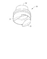
また、図3は、ボールシャッターの全体斜視図であり、図4は、ボールシャッターの正面図である。 FIG. 3 is an overall perspective view of the ball shutter, and FIG. 4 is a front view of the ball shutter.
また、図5は、図3のボールシャッターの突起を示す部分拡大図であり、図6は後側Oリングの全体斜視図である。 5 is a partially enlarged view showing the protrusion of the ball shutter in FIG. 3, and FIG. 6 is an overall perspective view of the rear O-ring.
また、図7は、筆記具の軸の正断面図であり、図8は、筆記具の軸の側断面図である。 FIG. 7 is a front sectional view of the writing instrument shaft, and FIG. 8 is a side sectional view of the writing instrument shaft.
図9は、前側Oリングの全体斜視図であり、図10は、本発明の乾き防止装置を備えたスライド式筆記具の全体が組み立てられた状態を示す正断面図であり、図11は、図10の側断面図である。 FIG. 9 is an overall perspective view of the front O-ring, and FIG. 10 is a front sectional view showing a state in which the entire slide-type writing instrument provided with the anti-drying device of the present invention is assembled. FIG. FIG.
また、図12〜図20は、本発明の乾き防止装置を備えたスライド式筆記具の作動状態を示す断面図である。 Moreover, FIGS. 12-20 is sectional drawing which shows the operating state of the slide-type writing instrument provided with the dry prevention apparatus of this invention.
本発明の筆記具は単一の本体または2分割可能な本体のいずれかによって構成された軸10を含む。特に、以下に詳細に説明する直接駆動方式で、迅速に開閉する乾き防止装置を軸10の内部に備える。
The writing instrument of the present invention includes a
ここで、本発明において、直接駆動方式とは、軸10のペン先孔13が乾き防止装置のボールシャッターによって密閉されているが、使用者がノック部29を押したときに、その力がボールシャッターに直接的に伝達されて、ボールシャッターが動作する方式をいう。
Here, in the present invention, the direct drive system means that the
また、軸10は、その円錐状の一端にペン先孔13が形成されており、他端にノック部29が結合されている。
Further, the
すなわち、使用者は本発明の筆記具の軸10を片手で握った後、親指で筆記具上端の押込部にあたるノック部29を押す。すると、ノック部29とカートリッジに連動するボールシャッターは、開放方向に回転角+90°回転しながら貫通路をペン先24の軸方向に一致させるようにするとともに、軸10のペン先孔13が開放する。
That is, after the user grasps the
その後、ペン先24はボールシャッターの貫通路を通じて、ペン先孔13の外部に突出することで、ユーザが筆記具を使用可能となる。
Thereafter, the nib 24 protrudes outside the
これとは反対に、使用者がノック部29を押すと、軸10の内部に設けられたスプリングによって、突出したペン先24が元の位置、つまり軸10の内部に収納される。このとき、ボールシャッターは閉じる方向に回転角90゜回転することによって、貫通路がペン先24の軸方向に垂直になるとともに、軸10のペン先孔13を閉じる。
On the contrary, when the user pushes the
図1を参照すれば、本発明による乾き防止装置を有するスライド式筆記具は主に五つの部品、すなわち、軸10、カートリッジ20、後側Oリング30、ボールシャッター40、前側Oリング50を含む。本発明の筆記具は、10個以上の部品を使用した従来の筆記具より少数の部品しか必要としないので、組み立てが容易である。
Referring to FIG. 1, a sliding writing instrument having a dry prevention device according to the present invention mainly includes five parts: a
本発明において、軸10は、ゴム、シリコン、軟質プラスチック素材の中の1種の材質を用いた射出成形またはモールド成形によって製作することができるので、一体のケースまたは二つの部分に分割されるケースが構成される。
In the present invention, the
また、軸10は、プラスチックの一般的な特性、つまり弾性、可撓性、伸縮性を有する。
The
ここで、軸10の一端には、カートリッジ20のペン先24が収納できる大きさのペン先孔13が形成され、軸10の他側にはカートリッジ20の本体が収納できる大きさのカートリッジ挿入孔14が形成されている。
Here, at one end of the
また、軸10の他端側の外周には、様々な形式に設計された動作制御部11が、軸10と一体型に形成されるか、または軸10と機構的に結合されている。望ましくは、動作制御部11は、係止部と係合することによって、ペン先24の突出状態または収納状態を維持する。
In addition, on the outer periphery of the other end side of the
また、円錐状に形成された軸10の一端には、ペン先孔13が形成されており、軸10の他端には、ノック部29を含む以下に説明する構成を収容することができる内径を有する挿入孔14が形成されている。筆記具の外部から見ると、ノック部29は挿入孔14に挿入されている。
Further, a
図1を参照すれば、ノック部29は、使用者がノック部29を押した力をカートリッジ20に伝達するように機能する。このようなノック部29は小径部と大径部を有するチューブ状である。ノック部の小径部側の端部は開口しており、ノック部の他端である大径部側の端部は閉塞している。
Referring to FIG. 1, the
また、本発明において、カートリッジ20は、大容量タンク部を有する。インクタンクは、その容量に対応する所定時間の間にペン先24を通じて、連続的かつ均一にインクを放出することができる
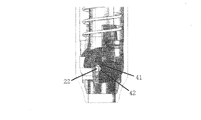
ここで、カートリッジ20の一端にはペン先24が設けられる。このようなペン先24は、ペン先延長軸23の一端に形成された孔に固定されていることによって、インクがペン先に供給される。
In the present invention, the
ペン先延長軸23は、中空で円形のチューブ状を有し、ペン先にインクを供給し、タンク部の直径より小さな直径である。
The pen
また、ペン先延長軸23の端部には、ペン先24が固定される。タンク部の内容物(すなわち、インク)は、タンク部からペン先24へ、筆記具の種類に対応する通常のインク供給方式(例えば、毛細管現象、圧力差、吸引など)によって供給される。
Also, a pen tip 24 is fixed to the end of the pen
ペン先24は、油性または水性インク用チップ、修正液排出用チップ、蛍光ペン用チップ、マーカーペン用チップまたは他の種類のチップが、筆記具の種類に応じて使用され、チップの種類に適したインク供給方式を使用することができる。 The nib 24 is a tip for oil-based or water-based ink, a tip for discharging a correction liquid, a tip for a fluorescent pen, a tip for a marker pen, or another type of tip depending on the type of writing instrument, and is suitable for the type of tip. An ink supply system can be used.
カートリッジ20は、動作制御部11に連動して動作する。係止部には、カートリッジを有する通常の筆記具で使用される通常の繰り出しメカニズムを使用することができる。
The
また、カートリッジ20は、動作制御部11に連動して動作する。大韓民国特許出願2003年第55414号、同第56940号に開示された繰り出しメカニズムであって、安全なノック式と同一または類似の繰り出しメカニズムを係止部に有する。この出願は、安全なノック式筆記具に関係し、本発明の出願人によって韓国特許庁に出願された。
Further, the
カートリッジ20が軸10のカートリッジ挿入孔14を通じて挿入された後、使用者が動作制御部11を操作したとき、前述した繰り出しメカニズムによって、ペン先24を軸10のペン先孔13から突出またはペン先孔13に収納するように、所定のストローク範囲内で往復移動することができ、所定のストロークの両端で一時的に停止することができる。
After the
図2に示すように、カートリッジのペン先を収容するペン先延長軸23の一端には、互いに対称に設けられるように、押込部22が形成されている。
As shown in FIG. 2, a push-in
各押込部22は、ペン先延長軸23の端部から上向きに突出するように形成されている。
Each pushing
スプリング7の一端は、カートリッジ20の段差部と当接している。
One end of the
スプリング7は、作動の際、カートリッジ20のストローク距離の範囲内で後側Oリング30またはカートリッジ20のいずれかを軸方向に押し出すように動作をする。
In operation, the
例えば、カートリッジ20とノック部29とが前に所定のストローク距離だけ動くとき、スプリング7は圧縮される。これにより、スプリング7は圧縮状態から伸張状態に復元しようとする弾性反発力を発生する。
For example, the
本発明において、カートリッジ20のストローク距離はノック部29のストローク距離と同一である。
In the present invention, the stroke distance of the
後側Oリング30及び前側Oリング50はゴム系の弾性材料を用い油圧プレスで成形されている。このため、後側Oリング及び前側Oリングは、撓みが繰り返されても、疲労に耐えることができる。さらに、後述する後側Oリング30、ボールシャッター40及び前側Oリング50が互いに表面が密着することによって、極めて効果的にインクの乾きを防止することができる。
The rear O-
ゴムタイプの弾性材質は熱硬化性のブチルゴムである。各部品は、その材質に適した方法で製作されることが好ましい。 The rubber type elastic material is thermosetting butyl rubber. Each part is preferably manufactured by a method suitable for the material.
また、後側Oリング30とボールシャッター40との間、又は、ボールシャッター40と前側Oリング50の間で、これらの部品が密着及び分離する際に発生するゴムの摩擦を最小にするために、これらの部品に潤滑油が塗布される。潤滑油は、粘度10万以上のシリコンオイルを使用する。
In addition, in order to minimize the friction of rubber generated when these components are in close contact and separated between the rear O-
図6に示すように、後側Oリング30は、密着部32とボールシャッター支持部31とを有する。
As shown in FIG. 6, the rear O-
密着部32はペン先延長軸23の直径に対応する直径を有する中空円筒であり、このため、密着部はカートリッジ20のペン先延長軸23の外周を密閉して取り囲むようになっている。
The
また、密着部32の一端からは、密着部32より大きな直径を有し、後述するボールシャッター40を収容するボールシャッター支持部31が延設されている。
Further, a ball
ボールシャッター支持部31は、半月形の突出したウィング部を有する。このウィング部は、ボールシャッター支持部31の端面の両側から突出するように形成されている。このため、ボールシャッター支持部は、ボールシャッターが突起の周囲で所定の場所から離脱しないでボールシャッターが回転するように、ボールシャッター40を支持する。
The ball
図3から図5に示すように、ボールシャッター40は、シャッター軸41、係止段42、シャッター部43、側面44、及び収容部45を含む。
As shown in FIGS. 3 to 5, the
シャッター部43は、ペン先孔13を開閉するドアとして機能する。ボールシャッター40は中空の球体である。、ボールシャッターの両側を通り、軸方向に定められた貫通路が形成されており、筆記具の作動時にカートリッジが出入する通路となる。
The
ボールシャッター40の形は、ボールシャッターの下部の球型のシャッター部43と、シャッター部43の両端から垂直になるように結合され、互いに平行な状態の一対の側面44とによって定められる。
The shape of the
シャッター部43は、後述される前側Oリング50と密接して、後側Oリング30と共にペン先を密閉し、ペン先のインクが揮発しないようする。
The
側面44は、略270゜の弧を有する扇形の平板で、側面の中心に係止段42が形成されている。
The
係止段42は凹状に形成され、カートリッジ20の押込部22からの力を直接的に受ける。
The locking
また、シャッター軸41は係止段42から両側面44の外方に垂直に突出した突起である。
The
図3に示すように、各シャッター軸41は、後述する軸10のシャッター軸支持部12に据えられるので、シャッター軸はシャッター軸支持部12の形状にしたがって動くようになる。
As shown in FIG. 3, each
各シャッター軸41は、丸みを帯びた形状の棒であり、カムのような形状となっている。そのため、各シャッター軸41が回転したとき、点線のシャッター軸41で示すように、シャッター軸の中心が上昇する。これは、ボールシャッター40が上に移動することを意味する。
Each
すなわち、各シャッター軸41の断面は、長軸aと短縮bを有する半月型である。シャッター軸が回転したとき、シャッター軸の中心は、aからbを減算した長さだけ上昇する。
That is, the cross section of each
したがって、ボールシャッターは、約0.3mm上昇しながら、前側Oリング50との接触状態から離れる。
Therefore, the ball shutter moves away from the contact state with the front O-
図7及び図8を参照すれば、シャッター軸支持部12は、軸10の内壁に形成されている。
7 and 8, the shutter
図7に示すように、シャッター軸支持部12は、ボールシャッター40が収容される位置で、シャッター軸41を支えるように、突出して設けられている。
As shown in FIG. 7, the shutter
シャッター軸支持部12の下部は平面である。シャッター軸支持部の上部は幅が広く、シャッター軸支持部の下部は幅が狭くなるように、シャッター軸支持部の両側は下部から上方に傾いている。
The lower part of the shutter
したがって、シャッター軸41はシャッター軸支持部12の下部及び傾斜部と接触しながら回転し、傾斜部に沿って上方に動き、ボールシャッター40を押し上げる。
Accordingly, the
図9に示すように、前側Oリング50は、密着部52と、ヘッド部51とを有する。
As shown in FIG. 9, the front O-
密着部52は、ボールシャッター40のシャッター部43と密着する部分である。さらに、密着部52は、軸10の内壁と密着するように、軸10に挿入される。
The
ヘッド部51は、軸10のペン先孔13の内壁及び端部と密着するように、軸10に挿入される。
The
図10及び図11の正断面図及び側断面図に示すように、前側Oリングの外表面が軸の内壁と密着して固定されるように、前側Oリング50は軸10に保持されている。特に、密着部52はボールシャッター40のシャッター43と密着している。
As shown in the front sectional view and the side sectional view of FIGS. 10 and 11, the front O-
ボールシャッター40のシャッター軸41は軸10のシャッター軸支持部12に据えられているので、シャッター軸はシャッター軸支持部12の範囲内で回転することができる。
Since the
後側Oリング30のボールシャッター支持部31はボールシャッター40を保持しており、特にボールシャッターの側面44を囲んでいる。このため、ボールシャッター40が不用意に外れにくいようになっている。
The ball
また、後側Oリング30の密着部32は、カートリッジ20のペン先延長軸23を囲んでいる。
Further, the
すなわち、ペン先24は、密着部32とシャッター43によって外気と接触することなく、ボールシャッター40の収容部45に収容されている。
That is, the pen tip 24 is accommodated in the
また、スプリング7の両端は、カートリッジ20の連結部の段部と後側Oリング30の段部の間に介在しているので、スプリングは、軸10に固定された後側Oリング30とカートリッジ20とをわずかな復元力で押している。
Further, both ends of the
図12から図20は、ストロークの開始位置からボールシャッター40がペン先孔13を閉鎖させるようにノック部が動作する状態を示す。すなわち、ボールシャッター40の貫通路はカートリッジ20の軸方向に垂直な方向に向かっている。
12 to 20 show a state in which the knock portion operates so that the
また、後述する前進方向と後退方向は、それぞれ、ペン先孔13の方向とノック部29の方向を意味する。
Further, a forward direction and a backward direction, which will be described later, mean the direction of the
特に、図12の閉じた状態は、図10及び図11の部品の組立が完了した状態である。 In particular, the closed state in FIG. 12 is a state in which the assembly of the components in FIGS. 10 and 11 is completed.
また、図12に示すように、ペン先24はボールシャッター40で囲まれた状態である。スプリング7は、カートリッジ20の連結部の段部と後側Oリング30の段部とに当接し、ペン先延長軸23を囲んでおり、スプリング7のわずかな復元力によって後側Oリング30とカートリッジ20が互いに押し力が加えられている。
Further, as shown in FIG. 12, the pen tip 24 is surrounded by a
また、押込部22は係止段42から離れている。
Further, the pushing
この状態で、図13に示すように、ノック部に力が加わったとき、カートリッジ20が前進する。このとき、押込部22がボールシャッター40の係止段42を押すことによって、ボールシャッターはシャッター軸41を中心に回転する。
In this state, as shown in FIG. 13, when a force is applied to the knock portion, the
この場合、シャッター軸41はシャッター軸支持部12上で回転する。
In this case, the
また、ボールシャッター40が回転することによって、前側Oリング50の密着部52との密着状態が解除される。
Further, when the
図14に示すように、ノック部がさらに続けて押されるとき、押込部22は係止段42を継続して押す。これによって、ボールシャッター40はさらに回転し、密着部52がシャッター43からさらに回転して、開く。
As shown in FIG. 14, when the knock portion is further pushed, the
また、図15に示すように、押込部22がさらに続けて前進することによって、ペン先24が密着部52とシャッター43の間の開口を通じて突出する。
In addition, as shown in FIG. 15, the push-in
また、シャッター軸41の回転によって、ボールシャッター40の全体が上昇する。
Further, the rotation of the
このため、図16に示すように、ペン先延長軸23と共にカートリッジ20のペン先も、ペン先孔13の外に突出する。ノック部が軸10にかかって、それ以上前進できなくなるまで、カートリッジ20は、ボールシャッター40の収容部45を通じて、前進し、ペン先孔13の外に突出する。このように軸10の外に突出して固定されたペン先24が使用される。
For this reason, as shown in FIG. 16, the pen tip of the
また、ペン先24を軸10の内部に収容し、ペン先を軸の内部に密閉するため、使用者はノック部を押して軸10からペン先を離脱させる。
Further, since the nib 24 is accommodated inside the
これにより、図17に示すように、カートリッジ20は後退する。このとき、押込部22がボールシャッター40の係止段42にかかって、係止段42を押し上げる。
Thereby, as shown in FIG. 17, the
係止段42が押し上げられることによって、ボールシャッター40はシャッター軸41を中心に回転する。
When the locking
このように、押込部22の係止段42が押し上げられ続けることによって、ボールシャッター40も回転する。これによって、図18に示すように、ペン先はボールシャッター40の収容部45に収容され、シャッター43はペン先孔13をゆっくりと塞ぐ。
In this way, the
また、ボールシャッター40は、ペン先孔側に移動しながら、カム状のシャッター軸41によって回転する。
The ball shutter 40 is rotated by a cam-
図20または図12に示すように、カートリッジ20が後退し続けるとき、押込部22が継続して係止段42を上向きに押し上げ、ボールシャッター40は前側Oリング50と密接して、ペン先孔13を閉じる。ペン先24は、ボールシャッター40の収容部45内に収容される。そして、ペン先は、後側Oリング30と前側Oリング50の間で密閉されることによって、インクの蒸発を最小化することになる。
As shown in FIG. 20 or FIG. 12, when the
Claims (9)
第1端のペン先孔と、内壁から突出したシャッター軸支持部とを有する中空の軸と;
前記ペン先孔の中心と対応する位置に前記軸の内部に収納され、前記軸の第2端に形成される挿入孔に挿入されるノック部と、そのペン先延長軸の一端に一対の押込部とを備えるカートリッジと;
前記カートリッジの一端を囲む後側Oリングと;
前記後側Oリングに保持され、ペン先を外部から遮断した状態で収容し、球面のシャッター部を備える中空の球形のボールシャッターと;
前記シャッター部と当接し、前記ペン先孔と密着する前側Oリングと;
第1端が前記カートリッジの下端段部と当接し、第2端が前記後側Oリングの段部と当接し、作動の際、前記カートリッジのストローク距離内で前記後側Oリング又は前記カートリッジのいずれか一方を軸方向に押し出すスプリングと;を備え、
前記押込部の作用によって前記ボールシャッターが回転して、前記シャッター部が前記前側Oリングを開口し、前記ペン先が前記ペン先孔から突出することを特徴とするスライド式筆記具。In a sliding writing instrument provided with means for preventing ink drying,
A hollow shaft having a pen tip hole at the first end and a shutter shaft support projecting from the inner wall;
A knock portion that is housed inside the shaft at a position corresponding to the center of the pen tip hole and is inserted into an insertion hole formed at the second end of the shaft, and a pair of pushes at one end of the pen tip extension shaft A cartridge comprising a portion;
A rear O-ring surrounding one end of the cartridge;
A hollow spherical ball shutter held by the rear O-ring and accommodated in a state where the pen tip is blocked from the outside, and having a spherical shutter portion;
A front O-ring that comes into contact with the shutter portion and comes into close contact with the pen tip hole;
The first end abuts the lower end step of the cartridge, the second end abuts the rear O-ring step, and during operation, within the stroke distance of the cartridge, the rear O-ring or the cartridge A spring for extruding one of them in the axial direction;
The slide-type writing instrument, wherein the ball shutter is rotated by the action of the pushing portion, the shutter portion opens the front O-ring, and the pen tip projects from the pen tip hole.
前記カートリッジのペン先延長軸の外周を気密に取り囲むように、前記ペン先延長軸に相当する直径を有する円筒状の密着部と;
前記密着部の直径より大きい直径を有し、前記ボールシャッターを保持するボールシャッター支持部と;を備えることを特徴とする請求項1に記載のスライド式筆記具。The rear O-ring is
A cylindrical contact portion having a diameter corresponding to the pen tip extension shaft so as to airtightly surround the outer periphery of the pen tip extension shaft of the cartridge;
The slide-type writing instrument according to claim 1, further comprising: a ball shutter support portion having a diameter larger than a diameter of the contact portion and holding the ball shutter.
前記ボールシャッターの下部に設けられる球面の前記シャッター部と;
前記シャッター部の両端から垂直に伸び、互いに平行に配置され、前記ボールシャッター支持部と面接触する一対の扇形の板状の側面と;
前記側面の中心に設けられ、凹状に形成され、前記カートリッジの押込部からの力を直接的に受ける係止段と;
両側面の前記係止段から外方に垂直に突出した突起であって、前記軸の前記シャッター軸支持部に支持されるシャッター軸と;を備えることを特徴とする請求項4に記載のスライド式筆記具。The ball shutter is
A spherical shutter portion provided at a lower portion of the ball shutter;
A pair of fan-shaped plate-like side surfaces extending vertically from both ends of the shutter portion and arranged in parallel to each other and in surface contact with the ball shutter support portion;
A locking step provided at the center of the side surface, formed in a concave shape and directly receiving a force from the pushing portion of the cartridge;
A projection which projects perpendicularly outwardly from the latching stage of both sides, and a shutter shaft which is supported by the shutter shaft support portion of the shaft; slide according to claim 4, characterized in that it comprises a Formula writing instrument.
前記ボールシャッターのシャッター部と密着し、前記軸の内壁と密接して、前記軸に挿入される密着部と;
前記ペン先孔の内壁及び端部と密着するように、軸に挿入されるヘッド部とを備えることを特徴とする請求項1に記載のスライド式筆記具。The front O-ring is
Close contact with the shutter portion of the ball shutter, close to the inner wall of the shaft, and a contact portion which is inserted into the shaft;
The slide-type writing instrument according to claim 1, further comprising a head portion inserted into the shaft so as to be in close contact with an inner wall and an end portion of the pen tip hole.
Applications Claiming Priority (3)
| Application Number | Priority Date | Filing Date | Title |
|---|---|---|---|
| KR10-2006-0038608 | 2006-04-28 | ||
| KR1020060038608A KR100772596B1 (en) | 2006-04-28 | 2006-04-28 | Slide type writing tools having device for preventing dryness |
| PCT/KR2007/002056 WO2007126253A1 (en) | 2006-04-28 | 2007-04-26 | Slide type writing tools having device for preventing dryness |
Publications (2)
| Publication Number | Publication Date |
|---|---|
| JP2009535233A JP2009535233A (en) | 2009-10-01 |
| JP4746129B2 true JP4746129B2 (en) | 2011-08-10 |
Family
ID=38655730
Family Applications (1)
| Application Number | Title | Priority Date | Filing Date |
|---|---|---|---|
| JP2009507598A Active JP4746129B2 (en) | 2006-04-28 | 2007-04-26 | Sliding writing instrument with dry prevention device |
Country Status (10)
| Country | Link |
|---|---|
| US (1) | US8177447B2 (en) |
| EP (1) | EP2013032B1 (en) |
| JP (1) | JP4746129B2 (en) |
| KR (1) | KR100772596B1 (en) |
| CN (1) | CN101432146B (en) |
| AU (1) | AU2007244071B2 (en) |
| BR (1) | BRPI0710799B1 (en) |
| MY (1) | MY152856A (en) |
| RU (1) | RU2401210C2 (en) |
| WO (1) | WO2007126253A1 (en) |
Cited By (1)
| Publication number | Priority date | Publication date | Assignee | Title |
|---|---|---|---|---|
| JP2016097682A (en) * | 2014-11-18 | 2016-05-30 | ジュ チョン,クァン | Push lock system for slide type writing tool |
Families Citing this family (27)
| Publication number | Priority date | Publication date | Assignee | Title |
|---|---|---|---|---|
| JP4973013B2 (en) * | 2006-05-31 | 2012-07-11 | ぺんてる株式会社 | Intrusive writing instrument |
| US7488130B2 (en) | 2007-02-01 | 2009-02-10 | Sanford, L.P. | Seal assembly for retractable instrument |
| JP5365013B2 (en) * | 2008-01-31 | 2013-12-11 | ぺんてる株式会社 | Retractable applicator |
| US8221012B2 (en) | 2008-11-07 | 2012-07-17 | Sanford, L.P. | Retractable instruments comprising a one-piece valve door actuating assembly |
| US8393814B2 (en) | 2009-01-30 | 2013-03-12 | Sanford, L.P. | Retractable instrument having a two stage protraction/retraction sequence |
| JP4973688B2 (en) * | 2009-05-20 | 2012-07-11 | ぺんてる株式会社 | Intrusive writing instrument |
| JP4973693B2 (en) * | 2009-06-09 | 2012-07-11 | ぺんてる株式会社 | Intrusive writing instrument |
| JP5496046B2 (en) * | 2010-10-06 | 2014-05-21 | ゼブラ株式会社 | Writing instrument |
| KR101289100B1 (en) * | 2011-07-11 | 2013-07-23 | 고명희 | Sign pen with button |
| TW201414620A (en) * | 2012-10-12 | 2014-04-16 | Xin Zhuan Invest Co Ltd | Pen having pen cap opened and closed by sliding |
| KR101455958B1 (en) * | 2013-09-09 | 2014-10-31 | 천광주 | Slide type writing tools having device for preventingdryness |
| CN106457877B (en) * | 2014-07-02 | 2018-08-28 | 株式会社樱花彩色笔 | Applicator |
| KR101774425B1 (en) | 2015-10-15 | 2017-09-12 | 주식회사 모리스 | Writing instrument having automatic sealing structure |
| JP6366757B1 (en) * | 2017-02-06 | 2018-08-01 | モリス コーポレーションMorris Corporation | Writing instrument with automatic sealing structure |
| US10214046B2 (en) * | 2017-02-10 | 2019-02-26 | Morris Corporation | Writing instrument having automatic sealing structure |
| JP6387129B2 (en) * | 2017-02-10 | 2018-09-05 | モリス コーポレーションMorris Corporation | Writing instrument assembly structure |
| US10183524B2 (en) * | 2017-02-10 | 2019-01-22 | Morris Corporation | Writing instrument having automatic sealing structure |
| CN108528097B (en) * | 2017-03-02 | 2020-03-10 | 莫里斯公司 | Writing instrument with automatic sealing structure |
| CN108528096B (en) * | 2017-03-02 | 2020-03-10 | 莫里斯公司 | Writing instrument with automatic sealing structure |
| KR101804319B1 (en) * | 2017-07-11 | 2017-12-04 | 천광주 | Slide type writing tools of sealing member having device for preventing dryness |
| KR102027070B1 (en) * | 2018-12-06 | 2019-09-30 | 칭따오 베스트 포인트 스테이셔너리 컴퍼니 리미티드 | Writing instruments equipped with anti-blur device |
| KR102443543B1 (en) | 2021-10-14 | 2022-09-14 | 김엽 | Things haunting mechanism and its sealing structure |
| KR102315494B1 (en) | 2021-01-20 | 2021-10-20 | 김엽 | Pen-type object retractable mechanism |
| KR102402977B1 (en) | 2021-10-14 | 2022-05-26 | 김엽 | Double twist structure and object haunting mechanism including the same |
| WO2022158684A1 (en) | 2021-01-20 | 2022-07-28 | 김엽 | Double-twist structure, object retractable mechanism comprising same and sealing structure thereof |
| EP4032721A1 (en) * | 2021-01-26 | 2022-07-27 | Société BIC | Writing instruments and methods thereof |
| CN115008925B (en) * | 2022-06-02 | 2023-05-16 | 得力集团有限公司 | Push type writing tool |
Citations (3)
| Publication number | Priority date | Publication date | Assignee | Title |
|---|---|---|---|---|
| JPH02124193A (en) * | 1988-11-02 | 1990-05-11 | Sophia Co Ltd | Pinball game machine |
| JPH0615728Y2 (en) * | 1989-07-17 | 1994-04-27 | セーラー万年筆株式会社 | Capless writing instrument |
| JP2005246971A (en) * | 2004-02-26 | 2005-09-15 | Morris Corp | Retractable writing implement with anti-drying unit |
Family Cites Families (15)
| Publication number | Priority date | Publication date | Assignee | Title |
|---|---|---|---|---|
| US2362948A (en) * | 1943-11-24 | 1944-11-14 | Sheaffer W A Pen Co | Fountain pen |
| US3583820A (en) * | 1969-06-30 | 1971-06-08 | Penn Corp | Writing instruments |
| DE8520506U1 (en) * | 1985-07-16 | 1985-08-29 | Glasa, Stefan, 2000 Hamburg | Closing tip for pens and drawing pens |
| JPS6444794A (en) * | 1987-08-12 | 1989-02-17 | Kodensha Kk | Open-close mechanism of nose opening section of cylindrical member |
| JPH02135288A (en) * | 1988-11-17 | 1990-05-24 | Asahi Glass Co Ltd | Fluorinated hydrocarbon-based azeotropic mixture |
| JPH02124193U (en) * | 1989-03-27 | 1990-10-12 | ||
| KR200162082Y1 (en) * | 1997-05-29 | 1999-12-01 | 박성영 | Cap opening & shutting device of writing instrument |
| CN2362710Y (en) * | 1998-11-11 | 2000-02-09 | 黄上原 | Ink-pen capable of preventing ink from evaporating and volatilizing |
| JP2001063271A (en) * | 1999-08-30 | 2001-03-13 | Hiroshi Yoshida | Writing instrument of capless type |
| US6371129B1 (en) * | 2000-02-18 | 2002-04-16 | Revlon Consumer Products Corporation | Dispenser for fluid materials |
| CA2475861A1 (en) * | 2002-02-13 | 2003-08-21 | Innodesk, Inc. | Capless retractable sealed marking instrument with forward chamber |
| KR100556569B1 (en) * | 2004-05-03 | 2006-03-06 | 주식회사 모리스 | Slide type writing tools having device for preventing dryness |
| TW200630241A (en) * | 2005-02-24 | 2006-09-01 | Flonto Corp | Opening and closing device for capless retractable marker pen |
| CN1699078B (en) * | 2005-06-10 | 2010-04-28 | 上海迈仕制笔有限公司 | Opening and closing device of uncovered retractable pen and uncovered retractable pen |
| KR101293138B1 (en) * | 2007-02-08 | 2013-08-12 | 주식회사 모리스 | Slide type writing tools having device for preventing dryness |
-
2006
- 2006-04-28 KR KR1020060038608A patent/KR100772596B1/en active IP Right Grant
-
2007
- 2007-04-26 RU RU2008146987/12A patent/RU2401210C2/en not_active IP Right Cessation
- 2007-04-26 WO PCT/KR2007/002056 patent/WO2007126253A1/en active Application Filing
- 2007-04-26 EP EP07746215A patent/EP2013032B1/en active Active
- 2007-04-26 US US12/299,119 patent/US8177447B2/en active Active
- 2007-04-26 JP JP2009507598A patent/JP4746129B2/en active Active
- 2007-04-26 BR BRPI0710799A patent/BRPI0710799B1/en active IP Right Grant
- 2007-04-26 CN CN2007800153950A patent/CN101432146B/en active Active
- 2007-04-26 MY MYPI20084177 patent/MY152856A/en unknown
- 2007-04-26 AU AU2007244071A patent/AU2007244071B2/en active Active
Patent Citations (3)
| Publication number | Priority date | Publication date | Assignee | Title |
|---|---|---|---|---|
| JPH02124193A (en) * | 1988-11-02 | 1990-05-11 | Sophia Co Ltd | Pinball game machine |
| JPH0615728Y2 (en) * | 1989-07-17 | 1994-04-27 | セーラー万年筆株式会社 | Capless writing instrument |
| JP2005246971A (en) * | 2004-02-26 | 2005-09-15 | Morris Corp | Retractable writing implement with anti-drying unit |
Cited By (1)
| Publication number | Priority date | Publication date | Assignee | Title |
|---|---|---|---|---|
| JP2016097682A (en) * | 2014-11-18 | 2016-05-30 | ジュ チョン,クァン | Push lock system for slide type writing tool |
Also Published As
| Publication number | Publication date |
|---|---|
| CN101432146A (en) | 2009-05-13 |
| KR20070106117A (en) | 2007-11-01 |
| WO2007126253A1 (en) | 2007-11-08 |
| EP2013032A1 (en) | 2009-01-14 |
| RU2008146987A (en) | 2010-06-10 |
| BRPI0710799B1 (en) | 2018-09-25 |
| JP2009535233A (en) | 2009-10-01 |
| MY152856A (en) | 2014-11-28 |
| AU2007244071B2 (en) | 2011-03-17 |
| EP2013032B1 (en) | 2012-07-18 |
| US20090136284A1 (en) | 2009-05-28 |
| BRPI0710799A2 (en) | 2011-08-09 |
| US8177447B2 (en) | 2012-05-15 |
| KR100772596B1 (en) | 2007-11-02 |
| RU2401210C2 (en) | 2010-10-10 |
| EP2013032A4 (en) | 2011-04-13 |
| CN101432146B (en) | 2010-12-29 |
| AU2007244071A1 (en) | 2007-11-08 |
Similar Documents
| Publication | Publication Date | Title |
|---|---|---|
| JP4746129B2 (en) | Sliding writing instrument with dry prevention device | |
| EP1866169B1 (en) | Retractable writing utensil having an airtight valve | |
| JP4746130B2 (en) | Sliding writing instrument with dry prevention device | |
| JP4609899B2 (en) | Writing instrument with dry prevention device | |
| KR100503569B1 (en) | Writing instrument | |
| JP5229708B2 (en) | Container with sealed structure | |
| KR102399598B1 (en) | Knock type pen | |
| JP3797426B2 (en) | Applicator | |
| US10434815B2 (en) | Slide-type writing instrument having drying-prevention device | |
| KR100549117B1 (en) | Slide type writing tools having device for preventing dryness | |
| KR20050105758A (en) | Slide type writing tools having device for preventing dryness | |
| KR100669364B1 (en) | Capless retractable marking pen | |
| JP4165748B2 (en) | Knock-type ballpoint pen | |
| JP2018008527A (en) | Thermochromic writing instrument | |
| JP3629685B2 (en) | Cap-type air tight writing instrument | |
| AU2006230044B2 (en) | Retractable writing utensil having an airtight valve | |
| JP2003251983A (en) | Writing utensil | |
| KR200357378Y1 (en) | Capless Marking Pen | |
| KR20170027560A (en) | Writing instrument having automatic sealing structure | |
| JP6327786B2 (en) | Thermochromic writing instrument | |
| KR20090070063A (en) | Improvement unity erase mark pen | |
| JP2002178681A (en) | Device for opening/closing airtight part of cap-less marker | |
| JP2004082431A (en) | Writing utensil |
Legal Events
| Date | Code | Title | Description |
|---|---|---|---|
| A131 | Notification of reasons for refusal |
Free format text: JAPANESE INTERMEDIATE CODE: A131 Effective date: 20101124 |
|
| A521 | Request for written amendment filed |
Free format text: JAPANESE INTERMEDIATE CODE: A523 Effective date: 20110217 |
|
| TRDD | Decision of grant or rejection written | ||
| A01 | Written decision to grant a patent or to grant a registration (utility model) |
Free format text: JAPANESE INTERMEDIATE CODE: A01 Effective date: 20110419 |
|
| A01 | Written decision to grant a patent or to grant a registration (utility model) |
Free format text: JAPANESE INTERMEDIATE CODE: A01 |
|
| A61 | First payment of annual fees (during grant procedure) |
Free format text: JAPANESE INTERMEDIATE CODE: A61 Effective date: 20110512 |
|
| FPAY | Renewal fee payment (event date is renewal date of database) |
Free format text: PAYMENT UNTIL: 20140520 Year of fee payment: 3 |
|
| R150 | Certificate of patent or registration of utility model |
Ref document number: 4746129 Country of ref document: JP Free format text: JAPANESE INTERMEDIATE CODE: R150 Free format text: JAPANESE INTERMEDIATE CODE: R150 |
|
| R250 | Receipt of annual fees |
Free format text: JAPANESE INTERMEDIATE CODE: R250 |
|
| R250 | Receipt of annual fees |
Free format text: JAPANESE INTERMEDIATE CODE: R250 |
|
| R250 | Receipt of annual fees |
Free format text: JAPANESE INTERMEDIATE CODE: R250 |
|
| R250 | Receipt of annual fees |
Free format text: JAPANESE INTERMEDIATE CODE: R250 |
|
| R250 | Receipt of annual fees |
Free format text: JAPANESE INTERMEDIATE CODE: R250 |
|
| R250 | Receipt of annual fees |
Free format text: JAPANESE INTERMEDIATE CODE: R250 |
|
| R250 | Receipt of annual fees |
Free format text: JAPANESE INTERMEDIATE CODE: R250 |
|
| R250 | Receipt of annual fees |
Free format text: JAPANESE INTERMEDIATE CODE: R250 |
|
| R250 | Receipt of annual fees |
Free format text: JAPANESE INTERMEDIATE CODE: R250 |
|
| R250 | Receipt of annual fees |
Free format text: JAPANESE INTERMEDIATE CODE: R250 |