JP4745977B2 - Method for converting a three-color input signal into a larger number of color signals - Google Patents
Method for converting a three-color input signal into a larger number of color signals Download PDFInfo
- Publication number
- JP4745977B2 JP4745977B2 JP2006538536A JP2006538536A JP4745977B2 JP 4745977 B2 JP4745977 B2 JP 4745977B2 JP 2006538536 A JP2006538536 A JP 2006538536A JP 2006538536 A JP2006538536 A JP 2006538536A JP 4745977 B2 JP4745977 B2 JP 4745977B2
- Authority
- JP
- Japan
- Prior art keywords
- color
- signal
- value
- common signal
- blue
- Prior art date
- Legal status (The legal status is an assumption and is not a legal conclusion. Google has not performed a legal analysis and makes no representation as to the accuracy of the status listed.)
- Expired - Lifetime
Links
- 238000000034 method Methods 0.000 title claims description 59
- 239000003086 colorant Substances 0.000 description 49
- 230000006870 function Effects 0.000 description 23
- OAICVXFJPJFONN-UHFFFAOYSA-N Phosphorus Chemical compound [P] OAICVXFJPJFONN-UHFFFAOYSA-N 0.000 description 20
- 239000011159 matrix material Substances 0.000 description 19
- 238000004364 calculation method Methods 0.000 description 13
- 238000012545 processing Methods 0.000 description 10
- 238000006243 chemical reaction Methods 0.000 description 9
- 238000010586 diagram Methods 0.000 description 9
- 238000010606 normalization Methods 0.000 description 7
- 238000012952 Resampling Methods 0.000 description 6
- 239000000654 additive Substances 0.000 description 5
- 230000000996 additive effect Effects 0.000 description 5
- 230000007423 decrease Effects 0.000 description 5
- 210000003127 knee Anatomy 0.000 description 5
- 230000009466 transformation Effects 0.000 description 5
- 239000013598 vector Substances 0.000 description 5
- 238000013459 approach Methods 0.000 description 4
- 238000012886 linear function Methods 0.000 description 4
- 239000004973 liquid crystal related substance Substances 0.000 description 4
- 230000008569 process Effects 0.000 description 4
- 230000008901 benefit Effects 0.000 description 3
- 230000008859 change Effects 0.000 description 3
- 239000000463 material Substances 0.000 description 3
- 230000009131 signaling function Effects 0.000 description 3
- 238000012937 correction Methods 0.000 description 2
- 230000003247 decreasing effect Effects 0.000 description 2
- 238000003384 imaging method Methods 0.000 description 2
- 230000004044 response Effects 0.000 description 2
- 238000005070 sampling Methods 0.000 description 2
- 238000000844 transformation Methods 0.000 description 2
- 230000007704 transition Effects 0.000 description 2
- 238000012935 Averaging Methods 0.000 description 1
- 230000002238 attenuated effect Effects 0.000 description 1
- 230000009286 beneficial effect Effects 0.000 description 1
- 238000007796 conventional method Methods 0.000 description 1
- 230000001419 dependent effect Effects 0.000 description 1
- 238000005516 engineering process Methods 0.000 description 1
- 230000003203 everyday effect Effects 0.000 description 1
- 239000005262 ferroelectric liquid crystals (FLCs) Substances 0.000 description 1
- 238000005286 illumination Methods 0.000 description 1
- 230000006872 improvement Effects 0.000 description 1
- 238000013507 mapping Methods 0.000 description 1
- 230000007935 neutral effect Effects 0.000 description 1
- 239000011368 organic material Substances 0.000 description 1
- 238000009877 rendering Methods 0.000 description 1
- 230000002441 reversible effect Effects 0.000 description 1
- 239000007787 solid Substances 0.000 description 1
- 238000001228 spectrum Methods 0.000 description 1
- 230000002123 temporal effect Effects 0.000 description 1
- 239000010409 thin film Substances 0.000 description 1
- 230000000007 visual effect Effects 0.000 description 1
Images


Classifications
-
- H—ELECTRICITY
- H04—ELECTRIC COMMUNICATION TECHNIQUE
- H04N—PICTORIAL COMMUNICATION, e.g. TELEVISION
- H04N1/00—Scanning, transmission or reproduction of documents or the like, e.g. facsimile transmission; Details thereof
- H04N1/46—Colour picture communication systems
- H04N1/56—Processing of colour picture signals
- H04N1/60—Colour correction or control
- H04N1/6016—Conversion to subtractive colour signals
- H04N1/6022—Generating a fourth subtractive colour signal, e.g. under colour removal, black masking
-
- G—PHYSICS
- G09—EDUCATION; CRYPTOGRAPHY; DISPLAY; ADVERTISING; SEALS
- G09G—ARRANGEMENTS OR CIRCUITS FOR CONTROL OF INDICATING DEVICES USING STATIC MEANS TO PRESENT VARIABLE INFORMATION
- G09G5/00—Control arrangements or circuits for visual indicators common to cathode-ray tube indicators and other visual indicators
- G09G5/02—Control arrangements or circuits for visual indicators common to cathode-ray tube indicators and other visual indicators characterised by the way in which colour is displayed
-
- G—PHYSICS
- G09—EDUCATION; CRYPTOGRAPHY; DISPLAY; ADVERTISING; SEALS
- G09G—ARRANGEMENTS OR CIRCUITS FOR CONTROL OF INDICATING DEVICES USING STATIC MEANS TO PRESENT VARIABLE INFORMATION
- G09G3/00—Control arrangements or circuits, of interest only in connection with visual indicators other than cathode-ray tubes
- G09G3/20—Control arrangements or circuits, of interest only in connection with visual indicators other than cathode-ray tubes for presentation of an assembly of a number of characters, e.g. a page, by composing the assembly by combination of individual elements arranged in a matrix no fixed position being assigned to or needed to be assigned to the individual characters or partial characters
- G09G3/22—Control arrangements or circuits, of interest only in connection with visual indicators other than cathode-ray tubes for presentation of an assembly of a number of characters, e.g. a page, by composing the assembly by combination of individual elements arranged in a matrix no fixed position being assigned to or needed to be assigned to the individual characters or partial characters using controlled light sources
- G09G3/30—Control arrangements or circuits, of interest only in connection with visual indicators other than cathode-ray tubes for presentation of an assembly of a number of characters, e.g. a page, by composing the assembly by combination of individual elements arranged in a matrix no fixed position being assigned to or needed to be assigned to the individual characters or partial characters using controlled light sources using electroluminescent panels
- G09G3/32—Control arrangements or circuits, of interest only in connection with visual indicators other than cathode-ray tubes for presentation of an assembly of a number of characters, e.g. a page, by composing the assembly by combination of individual elements arranged in a matrix no fixed position being assigned to or needed to be assigned to the individual characters or partial characters using controlled light sources using electroluminescent panels semiconductive, e.g. using light-emitting diodes [LED]
- G09G3/3208—Control arrangements or circuits, of interest only in connection with visual indicators other than cathode-ray tubes for presentation of an assembly of a number of characters, e.g. a page, by composing the assembly by combination of individual elements arranged in a matrix no fixed position being assigned to or needed to be assigned to the individual characters or partial characters using controlled light sources using electroluminescent panels semiconductive, e.g. using light-emitting diodes [LED] organic, e.g. using organic light-emitting diodes [OLED]
-
- H—ELECTRICITY
- H04—ELECTRIC COMMUNICATION TECHNIQUE
- H04N—PICTORIAL COMMUNICATION, e.g. TELEVISION
- H04N1/00—Scanning, transmission or reproduction of documents or the like, e.g. facsimile transmission; Details thereof
- H04N1/46—Colour picture communication systems
- H04N1/56—Processing of colour picture signals
- H04N1/60—Colour correction or control
-
- G—PHYSICS
- G09—EDUCATION; CRYPTOGRAPHY; DISPLAY; ADVERTISING; SEALS
- G09G—ARRANGEMENTS OR CIRCUITS FOR CONTROL OF INDICATING DEVICES USING STATIC MEANS TO PRESENT VARIABLE INFORMATION
- G09G2300/00—Aspects of the constitution of display devices
- G09G2300/04—Structural and physical details of display devices
- G09G2300/0439—Pixel structures
- G09G2300/0452—Details of colour pixel setup, e.g. pixel composed of a red, a blue and two green components
-
- G—PHYSICS
- G09—EDUCATION; CRYPTOGRAPHY; DISPLAY; ADVERTISING; SEALS
- G09G—ARRANGEMENTS OR CIRCUITS FOR CONTROL OF INDICATING DEVICES USING STATIC MEANS TO PRESENT VARIABLE INFORMATION
- G09G2320/00—Control of display operating conditions
- G09G2320/02—Improving the quality of display appearance
-
- G—PHYSICS
- G09—EDUCATION; CRYPTOGRAPHY; DISPLAY; ADVERTISING; SEALS
- G09G—ARRANGEMENTS OR CIRCUITS FOR CONTROL OF INDICATING DEVICES USING STATIC MEANS TO PRESENT VARIABLE INFORMATION
- G09G3/00—Control arrangements or circuits, of interest only in connection with visual indicators other than cathode-ray tubes
- G09G3/20—Control arrangements or circuits, of interest only in connection with visual indicators other than cathode-ray tubes for presentation of an assembly of a number of characters, e.g. a page, by composing the assembly by combination of individual elements arranged in a matrix no fixed position being assigned to or needed to be assigned to the individual characters or partial characters
Landscapes
- Engineering & Computer Science (AREA)
- Physics & Mathematics (AREA)
- Computer Hardware Design (AREA)
- General Physics & Mathematics (AREA)
- Theoretical Computer Science (AREA)
- Multimedia (AREA)
- Signal Processing (AREA)
- Control Of Indicators Other Than Cathode Ray Tubes (AREA)
- Color Image Communication Systems (AREA)
- Control Of El Displays (AREA)
- Image Processing (AREA)
- Facsimile Image Signal Circuits (AREA)
Description
本発明は、4色以上の原色を有するカラーOLED表示装置上での表示のために3色カラー画像信号をカラー処理することに関する。 The present invention relates to color processing of a three-color image signal for display on a color OLED display device having four or more primary colors.
加色型ディジタルカラー画像表示装置はよく知られており、また陰極線管、液晶変調器、および有機発光ダイオード(OLED)のような固体発光体といった種々の技術に基づいている。一般のOLEDカラー表示装置では1ピクセルは、赤色と緑色と青色に色づけされたOLEDを含む。これらの発光原色は、色域を画定し、またこれら3つのOLEDの各々からの照明を加色的に組み合わせることによって、すなわち人間の視覚システムの統合能力によって、幅広い種々のカラーが達成できる。OLEDは、電磁スペクトルの所望部分のエネルギーを放射するようにドーピングされた有機材料を直接使用してカラーを生成するために使用でき、あるいは代替として広帯域発光(外見的には白色)OLEDが赤色、緑色、青色を達成するためにカラーフィルタで減衰させられる可能性がある。 Additive digital color image display devices are well known and are based on various technologies such as cathode ray tubes, liquid crystal modulators, and solid state light emitters such as organic light emitting diodes (OLEDs). In a typical OLED color display device, one pixel includes OLEDs colored red, green, and blue. These luminescent primaries define a color gamut and a wide variety of colors can be achieved by additively combining the illumination from each of these three OLEDs, ie, by the integrated capabilities of the human visual system. OLEDs can be used to produce color directly using organic materials doped to emit the energy of the desired portion of the electromagnetic spectrum, or alternatively, broadband emission (appearing white) OLEDs are red, It may be attenuated with a color filter to achieve green and blue.
電力効率および/または経時輝度安定性を改善するために赤色、緑色および青色OLEDと共に白色またはほぼ白色のOLEDを使用することは可能である。電力効率および/または経時輝度安定性を改善するための他の可能性は、一つ以上の追加の非白色OLEDの使用を含む。しかしながら、カラー表示装置上での表示を予定されている画像その他のデータは典型的には、3つのチャネルにおいて、すなわち標準(例えばRGB)または特定(例えば測定されたCRT蛍光体)のセットの原色に対応する3つの信号を有する3つのチャネルにおいて、記憶および/または伝送される。このデータが典型的には発光素子の特定の空間配置を想定するようにサンプリングされることを認識することも重要である。OLED表示装置ではこれらの発光素子は典型的には、一平面上に並べて配置される。したがって、もし受信画像データが3色カラー表示装置上での表示のためにサンプリングされるのであれば、これらのデータはまた、3チャネル表示装置に使用される3つのOLEDよりむしろ1ピクセル当たり4個のOLEDを有する表示装置での表示のために再サンプリングされなくてはならないであろう。 It is possible to use white or nearly white OLEDs with red, green and blue OLEDs to improve power efficiency and / or luminance stability over time. Other possibilities for improving power efficiency and / or luminance stability over time include the use of one or more additional non-white OLEDs. However, images and other data that are scheduled to be displayed on a color display device are typically primary colors in three channels, ie standard (eg RGB) or specific (eg measured CRT phosphor) set. Are stored and / or transmitted in three channels with three signals corresponding to. It is also important to recognize that this data is typically sampled to assume a specific spatial arrangement of light emitting elements. In an OLED display device, these light emitting elements are typically arranged side by side on one plane. Thus, if the received image data is sampled for display on a three-color display, these data are also four per pixel rather than the three OLEDs used in a three-channel display. Would have to be resampled for display on a display device having a number of OLEDs.
CMYK印刷の分野では、下色除去(UCR)または灰色成分交換として知られる、RGBからCMYKへの、より明確にはCMYからCMYKへの変換が行われる。これらの最も基本的な点でこれらの変換は、CMY値のある小部分を差し引いて、この量をK値に加算する。これらの方法は、典型的には不連続階調システムを含むので、画像構造限界によって複雑にされるが、減色型CMYK画像の白色はそれが印刷される基底物によって決定されるので、これらの方法はカラー処理に関しては比較的単純なままにとどまる。連続階調加色型カラーシステムにアナログ的アルゴリズムを適用する試みは、追加原色が表示システムの白色点とはカラーが異なる場合には、色誤差を引き起こすであろう。更にこれらのシステムで使用されるカラーは典型的には、上下にオーバーレイでき、したがって4色を表示する際にデータを空間的に再サンプリングする必要はない。 In the field of CMYK printing, there is a conversion from RGB to CMYK, more specifically CMY to CMYK, known as undercolor removal (UCR) or gray component exchange. At their most basic point, these transformations subtract a small portion of the CMY value and add this amount to the K value. These methods typically involve a discontinuous tone system and are therefore complicated by image structure limitations, but since the white color of a subtractive CMYK image is determined by the basis on which it is printed, these methods The method remains relatively simple with respect to color processing. Attempts to apply analog algorithms to a continuous tone additive color system will cause color errors if the additional primary color is different in color from the white point of the display system. In addition, the colors used in these systems typically can be overlaid on top and bottom, so there is no need to spatially resample the data when displaying four colors.
順次フィールド型カラー投影システムの分野では、赤色、緑色、青色の原色と組み合わせて白色の原色を使用することが知られている。白色は、投影されるカラーの全部ではなくても一部の彩度を本来的に減少させる赤色、緑色、青色の原色によって与えられる明るさを強めるために投影される。2002年9月17日に発行されたUS6,453,067にMorganらによって提案された方法は、赤色、緑色、青色の強度の最小値に依存する白色原色の強度を計算し、その後スケーリング(増減)を介して修正された赤色、緑色、青色の強度を計算することへのアプローチを教えている。このスケーリングは見かけ上、白色によって与えられる明るさの追加の結果生じる色誤差を修正しようとすることであるが、スケーリングによる単純な修正は、白色の追加に際に、失われるすべての彩度をすべての色に関して復元することは決してないであろう。この方法における減算ステップの欠落は、少なくとも一部のカラーにおける色誤差を確実にする。更にMorganの開示は、白色原色が問題を十分に解決することなく、表示装置の所望の白色点とは色が異なる場合に発生する問題を説明している。この方法は、表示装置の白色点の周りの狭い範囲に白色原色の選択を効果的に限定する、平均有効白色点を単純に受け入れている。赤色、緑色、青色、白色の要素は互いに空間的にオーバーラップするように投影されるので、この4色装置上での表示のためにデータを空間的に再サンプリングする必要はない。 In the field of sequential field color projection systems, it is known to use a white primary color in combination with red, green and blue primary colors. White is projected to enhance the brightness provided by the primary colors of red, green, and blue that inherently reduce some, if not all, of the projected colors. The method proposed by Morgan et al. In US Pat. No. 6,453,067 issued September 17, 2002 calculates the intensity of the white primary color, which depends on the minimum of the red, green, and blue intensity, and then scales (increases or decreases). ) Teaches an approach to calculating corrected red, green and blue intensities via. This scaling apparently seeks to correct the color error that results from adding the brightness given by white, but a simple correction by scaling reduces all the saturation that is lost when adding white. It will never be restored for all colors. The lack of a subtraction step in this method ensures a color error in at least some colors. Further, Morgan's disclosure describes the problem that occurs when the white primary color does not fully solve the problem and the color is different from the desired white point of the display device. This method simply accepts an average effective white point that effectively limits the selection of the white primaries to a narrow range around the white point of the display device. Since the red, green, blue and white elements are projected so as to spatially overlap each other, there is no need to resample the data spatially for display on this four-color device.
赤色、緑色、青色、白色のピクセルを有するカラー液晶表示装置を駆動するために、TFT−LCD with RGBW Color System(RGBWカラーシステムを有するTFT−LCD(薄膜トランジスタ液晶表示装置))、SID 03 Digest、pp.1212−1215に同様なアプローチがLeeらによって説明されている。Leeらは、赤色、緑色、青色、白色信号の最小値として白色信号を計算し、それから最高の輝度向上のゴールによって、全部ではなく一部の色誤差を修正するために赤色、緑色、青色信号をスケール合わせ(増減)する。Leeらの方法は、Morganの方法と同じ色誤差を蒙り、赤色、緑色、青色、白色要素のアレイに対する受信3色カラーデータの空間的再サンプリングの参照は行われない。 TFT-LCD with RGBW Color System (TFT-LCD (Thin Film Transistor Liquid Crystal Display) with RGBW color system), SID 03 Digest, pp, to drive a color liquid crystal display with red, green, blue and white pixels . A similar approach is described by Lee et al. Lee et al. Calculate the white signal as the minimum of the red, green, blue and white signals, and then the red, green and blue signals to correct some but not all of the color error with the goal of maximum brightness enhancement. Adjust the scale (increase / decrease). The Lee et al. Method suffers the same color error as the Morgan method and no reference is made to the spatial resampling of the received tri-color data for an array of red, green, blue and white elements.
強誘電体液晶表示装置の分野では、もう一つの方法が、1999年7月27に発行されたUS5,929,843にTaniokaによって提示されている。Taniokaの方法は、R、G、B信号の最小値をW信号に割り当てて、R、G、B信号の各々から同じ信号を差し引く、よく知られたCMYKアプローチに類似したアルゴリズムに従っている。空間的人為構成物を避けるためにこの方法は、低い輝度レベルで、より滑らかなカラーという結果をもたらす最小信号に印加される可変スケール係数を教えている。CMYKアルゴリズムとのその類似性の故に、この方法は、上述と同じ問題、すなわち表示装置白色点の色とは異なる色を有する白色ピクセルが色誤差を引き起こすであろうという問題に悩まされる。Morganら(上記に参照されたUS6,453,067)と同様に典型的には、カラー要素は互いに空間的にオーバーラップするように投影され、したがって、データの空間的再サンプリングの必要はない。 In the field of ferroelectric liquid crystal display devices, another method is presented by Tanioka in US Pat. No. 5,929,843 issued July 27, 1999. Tanio's method follows an algorithm similar to the well-known CMYK approach that assigns the minimum value of the R, G, B signals to the W signal and subtracts the same signal from each of the R, G, B signals. In order to avoid spatial artifacts, this method teaches a variable scale factor applied to the smallest signal that results in a smoother color at lower luminance levels. Due to its similarity to the CMYK algorithm, this method suffers from the same problem as described above, that is, white pixels having a color different from the color of the display device white point will cause a color error. Similar to Morgan et al. (US Pat. No. 6,453,067 referenced above), the color elements are typically projected so as to spatially overlap each other, thus eliminating the need for spatial resampling of the data.
従来技術では各可視空間位置にフルカラーデータを与える積層型OLED表示装置が論じられてきたが、OLED表示装置は一般に、単一平面に配置される多数色のOLEDから構成される。表示装置が異なる空間位置を有するカラー発光素子を備えるとき、空間配置のためにデータをサンプリングすることが知られている。例えば1994年8月23日にBenzschawelらに発行されたUS5,341,153は、異なるカラーの発光素子が異なる空間位置を有する低解像度液晶表示装置上に高解像度カラー画像を表示するための方法を論じている。この方法を使用すると、各発光素子のための信号を生成するためにサンプリングされる原画像の空間位置と領域は、サブピクセルのレンダリング(描画)を与えるフォーマットにデータをサンプリングするときに考慮される。この特許は、4色の異なるカラー発光素子を有する表示装置のためのデータのサンプリングを与えることに言及しているが、これは4色の異なるカラー発光素子を有する表示装置上での表示のために適当である画像信号に従来の3色カラー画像信号を変換するための方法を与えない。更にBenzschawelらは、入力データが表示装置よりも解像度の高い画像ファイルから生じて、すべてのピクセル位置ですべてのカラー発光素子のための情報を含むことを想定している。 While the prior art has discussed stacked OLED displays that provide full color data at each visible space location, OLED displays are generally composed of multiple color OLEDs arranged in a single plane. It is known to sample data for spatial arrangement when the display device comprises color light emitting elements having different spatial positions. For example, US Pat. No. 5,341,153 issued to Benzchawel et al. On August 23, 1994 describes a method for displaying a high resolution color image on a low resolution liquid crystal display device in which different color light emitting elements have different spatial positions. Arguing. Using this method, the spatial position and region of the original image sampled to generate a signal for each light emitting element is taken into account when sampling the data into a format that provides sub-pixel rendering. . This patent mentions providing data sampling for a display device having four different color light emitting elements, which is for display on a display device having four different color light emitting elements. No conventional method for converting a three-color image signal to an image signal that is suitable for the above. Benschchawel et al. Further assume that the input data comes from an image file with a higher resolution than the display device and contains information for all color light emitting elements at every pixel location.
従来技術はまた、発光素子の一つの意図された空間配置から発光素子の第2の空間配置に画像データを再サンプリングするための方法を含む。2003年2月20に発行されたBrown Elliottらによる米国特許出願第2003/0034992A1号は、3色を有する発光素子の一つの空間配置を有する表示装置上での表示を意図されたデータを3色カラー発光素子の異なる空間配置を有する表示装置に再サンプリングする方法を論じている。明確には、この特許出願は、発光素子の従来配置を有する表示装置上での表示を意図された3色カラーデータを、発光素子の代替配置を有する表示装置上での表示を意図された3色カラーデータに再サンプリングすることを論じている。一つの意図された空間配置から空間的にオーバーラップする発光素子を有する論理表示装置にデータを再サンプリングすることは可能であるが、画像の3色カラー画像信号から4色カラーOLED表示装置への変換を実行し、それからOLED表示装置の空間配置にこのデータを再サンプリングすることは、計算量的に集中的である。 The prior art also includes a method for resampling image data from one intended spatial arrangement of light emitting elements to a second spatial arrangement of light emitting elements. US Patent Application No. 2003 / 0034992A1 issued by Brown Elliott et al., Issued February 20, 2003, discloses three colors of data intended for display on a display device having one spatial arrangement of light emitting elements having three colors. A method of resampling to display devices having different spatial arrangements of color light emitting elements is discussed. Specifically, this patent application is intended to display three color data intended for display on a display device having a conventional arrangement of light emitting elements, and to display on a display device having an alternative arrangement of light emitting elements. It discusses resampling to color color data. Although it is possible to resample data from a single intended spatial arrangement to a logical display device having spatially overlapping light emitting elements, the three-color image signal of the image to a four-color OLED display device. Performing the conversion and then resampling this data into the spatial layout of the OLED display is computationally intensive.
したがって、画像その他のデータを担持する3色カラー入力信号を空間的にオーバーラップしない4色以上の出力信号に変換するための改善された方法が必要である。 Therefore, there is a need for an improved method for converting a three color input signal carrying images and other data into an output signal of four or more colors that do not spatially overlap.
この必要性は、4色カラー出力信号に対応する光を放射する発光体を有する表示装置を駆動するために、3色の色域画定原色に対応する3色カラー入力信号(R,G,B)を該色域画定原色と一つの追加原色Wとに対応する4色のカラー出力信号(R’,G’,B’,W)に変換するための方法であって、現在ピクセルと隣接ピクセルとに関して3色カラー入力信号(R,G,B)の関数F1として共通信号値Sを計算するステップと、現在ピクセルと隣接ピクセルとに関する共通信号に基づいて最終共通信号値S’を決定するステップと、前記最終共通信号値S’の関数F2の値を計算して、この値を3色カラー入力信号(R,G,B)の各々に加算することによって前記3色カラー信号(R’,G’,B’)を計算するステップと、前記最終共通信号値S’の関数F3として前記出力信号Wを計算するステップと、を含む方法を提供することによって満たされる。 This need is met by driving a three-color input signal (R, G, B) corresponding to three color gamut defining primaries to drive a display device having a light emitter that emits light corresponding to the four color output signal. ) To four color output signals (R ′, G ′, B ′, W) corresponding to the color gamut defining primary color and one additional primary color W, the current pixel and the adjacent pixel Calculating a common signal value S as a function F1 of the three-color input signal (R, G, B) with respect to and determining a final common signal value S ′ based on the common signal for the current pixel and neighboring pixels And calculating the value of the function F2 of the final common signal value S ′ and adding this value to each of the three color input signals (R, G, B). Calculating G ′, B ′), Calculating the output signal W as a function F3 of the final common signal value S ', they are met by providing a method comprising the.
本発明は、OLED表示システムにおけるエッジ情報を保存する仕方で、3つの空間的にオーバーラップしない発光素子を有する表示装置上での表示のためにサンプリングされた可能性のある3色カラー入力画像信号を4色以上のカラー画像信号に変換するための効率的な方法を提供するという利点を有する。 The present invention is a method for preserving edge information in an OLED display system and a three-color color input image signal that may be sampled for display on a display device having three spatially non-overlapping light emitting elements. Has the advantage of providing an efficient method for converting the image into a color image signal of four or more colors.
本発明は、画像その他のデータを担持する3色カラー入力信号を4色以上の原色を有する加色型表示装置上での表示のための4色以上のカラー出力信号に変換するための方法に向けられている。本発明は、例えば3つの空間的にオーバーラップしない発光素子を有する表示装置上での表示のためにサンプリングされた3色のRGB入力カラー信号を、各々が4色のうちの1色の光を放射する発光素子から構成されたピクセルを有する4色カラーOLED表示装置を駆動するための4色カラー信号に変換するために有用である。 The present invention provides a method for converting a three-color input signal carrying images and other data into a color output signal of four or more colors for display on an additive display device having four or more primary colors. Is directed. In the present invention, for example, three RGB input color signals sampled for display on a display device having three spatially non-overlapping light emitting elements are used, each of which has one of four colors of light. It is useful for converting to a four color signal for driving a four color OLED display having pixels composed of emitting light emitting elements.
図1は、4色カラーOLED表示装置の原色の仮説的表現を表示する1931CIE色度図を示す。赤原色2と緑原色4と青原色6は、色域画定三角形8によって仕切られた色域を画定する。追加原色10は、この例では図の中心付近にあるので、実質的に白色であるが、必ずしも表示装置の白色点にあるわけではない。色域8の外側に代替の追加原色12が示されており、その使用法については後述する。
FIG. 1 shows a 1931 CIE chromaticity diagram that displays a hypothetical representation of the primary colors of a four color OLED display. The red primary color 2, the green primary color 4, and the blue primary color 6 define a color gamut partitioned by a color
所定の表示装置は、一般的に当分野で周知の方法を介してハードウエアまたはソフトウエアによって調整可能ではあるが、この例の目的のために固定されている白色点を持っている。この白色点は、最も高いアドレス可能範囲にまで移動させられる三原色の組合せ、この例では赤色、緑色、青色の原色の組合せの結果得られる色である。白色点は、下記の方程式: A given display device has a white point that is fixed for the purposes of this example, although it is generally adjustable by hardware or software via methods well known in the art. This white point is the color resulting from the combination of the three primary colors that are moved to the highest addressable range, in this example the combination of the red, green and blue primaries. The white point is the following equation:

によってCIE XYZ三刺激値に変換され得る、一般にxyY値と呼ばれるその色度座標とその輝度とによって規定される。 Is defined by its chromaticity coordinates, commonly referred to as xyY values, and its brightness, which can be converted into CIE XYZ tristimulus values.
3個すべての三刺激値が輝度Yによってスケール合わせ(増減)されることに留意すると、XYZ三刺激値がもっとも厳密な意味でcd/m2のような輝度の単位を有することは明らかである。しかしながら、白色点輝度はしばしば、これを効果的にパーセント輝度にする100という値を有する無次元量に正規化される。ここで用語「輝度(luminance)」は常に、パーセント輝度を指すために使用され、XYZ三刺激値は同じ意味で使用されるであろう。こうして、(0.3127,0.3290)というxy色度値を有するD65という共通表示装置白色点は、(95.0,100.0,108.9)というXYZ三刺激値を有する。 Noting that all three tristimulus values are scaled (increased or decreased) by luminance Y, it is clear that XYZ tristimulus values have a unit of luminance such as cd / m2 in the strictest sense. However, the white point luminance is often normalized to a dimensionless quantity having a value of 100 that effectively makes it a percent luminance. Here the term “luminance” will always be used to refer to percent luminance, and XYZ tristimulus values will be used interchangeably. Thus, the common display device white point D65 having an xy chromaticity value of (0.3127, 0.3290) has an XYZ tristimulus value of (95.0, 100.0, 108.9).
この例では赤色、緑色、青色の原色である3つの表示装置原色の表示装置白色点と色度座標は共に、蛍光体マトリックスを指定し、その計算法は当分野では周知である。また歴史的には発光蛍光体を使用するCRT表示装置に関連しているが日常用語「蛍光体マトリックス」が物理的蛍光体材料による、またはよらない表示の数学的記述に更に一般的に使用され得ることもよく知られている。蛍光体マトリックスは、強度をXYZ三刺激値に変換し、表示装置であってこの逆にXYZ三刺激値を強度に変換する加色型カラーシステムを効果的にモデル化する。 In this example, the display device white point and chromaticity coordinates of the three display device primary colors, which are the primary colors of red, green, and blue, both specify a phosphor matrix, and the calculation method is well known in the art. Also, historically related to CRT displays that use luminescent phosphors, the everyday term “phosphor matrix” is more commonly used in mathematical descriptions of displays with or without physical phosphor materials. It is also well known to obtain. The phosphor matrix effectively models an additive color system that converts intensities into XYZ tristimulus values and is a display device, and vice versa, converts XYZ tristimulus values into intensities.
ある原色の強度はここでは、この原色の輝度に比例する値として規定され、三原色の各々の単位強度の組合せが、この表示装置白色点のXYZ三刺激値に等しいXYZ三刺激値を有するカラー刺激を生成するようにスケール合わせ(増減)される。この規定はまた、蛍光体マトリックスの項のスケーリング(増減)を拘束する。D65白色点を有する、それぞれ(0.637,0.3592)、(0.2690,0.6508)、(0.1441,0.1885)という赤、緑、青の原色色度座標を持ったOLED表示例は、蛍光体マトリックスM3: The intensity of a primary color is defined here as a value proportional to the brightness of the primary color, and the combination of unit intensity of each of the three primary colors has an XYZ tristimulus value equal to the XYZ tristimulus value of the display device white point. Is scaled (increased or decreased) to produce This definition also constrains the scaling of the phosphor matrix terms. D65 white point with red, green and blue primary chromaticity coordinates of (0.637, 0.3592), (0.2690, 0.6508) and (0.1441, 0.1885) respectively. An example of OLED display is phosphor matrix M3:
を有する。蛍光体マトリックスM3に列ベクトルとしての強度を掛けると、下記の方程式: Have Multiplying the phosphor matrix M3 by the intensity as a column vector, the following equation:
のように、XYZ三刺激値になる。ここでI1は赤原色の強度、I2は緑原色の強度、I3は青原色の強度である。 As shown, the XYZ tristimulus values are obtained. Here, I1 is the intensity of the red primary color, I2 is the intensity of the green primary color, and I3 is the intensity of the blue primary color.
蛍光体マトリックスは典型的には線形マトリックス変換であるが、蛍光体マトリックス変換の概念が強度からXYZ三刺激値に導く、またはその逆である任意の変換または任意の一連の変換に一般化できることは、留意されるべきである。 The phosphor matrix is typically a linear matrix transformation, but the concept of phosphor matrix transformation can be generalized to any transformation or any series of transformations that lead from intensity to XYZ tristimulus values, or vice versa Should be noted.
蛍光体マトリックスはまた、4色以上の原色を処理するように一般化することもできる。この例は、白色に近いがD65白色点にないxy色度座標(0.3405,0.3530)を有する追加原色を含む。100であるように任意に選択された輝度において、追加原色は、(96.5,100.0,86.8)というXYZ三刺激値を有する。これら3つの値は、便宜上、XYZ三刺激値が赤色、緑色、青色の原色によって画定される色域内で可能な最大値にスケール合わせされているが、第4の列を生成するために修正なしで蛍光体マトリックスM3に追加できる。蛍光体マトリックスM4は下記のとおりである: The phosphor matrix can also be generalized to process more than four primary colors. This example includes additional primary colors with xy chromaticity coordinates (0.3405, 0.3530) that are close to white but not at the D65 white point. At a luminance arbitrarily chosen to be 100, the additional primary colors have an XYZ tristimulus value of (96.5, 100.0, 86.8). For convenience, these three values are scaled to the maximum possible XYZ tristimulus value within the color gamut defined by the red, green, and blue primaries, but unmodified to produce the fourth column. Can be added to the phosphor matrix M3. The phosphor matrix M4 is as follows:
前に提示された方程式に類似する方程式は、原色の組合せが表示装置:
内に有するXYZ三刺激値への、赤色と緑色と青色と追加の原色に対応する強度の4値ベクトルの変換を可能にするであろう。 It will allow the conversion of quaternary vectors of intensities corresponding to red, green, blue and additional primaries to the XYZ tristimulus values they contain.
一般に蛍光体マトリックスの値は、その反転に存在し、これはXYZ三刺激値でのカラーの指定を考慮しており、表示装置上にこのカラーを生成するために必要とされる強度という結果をもたらす。無論、色域は、その再生が可能であるカラーの範囲を限定し、また色域外XYZ三刺激値指定は、範囲[0,1]外の強度という結果をもたらす。この状況を避けるために既知の色域マッピング手法が適用できるが、これらの使用は本発明にほとんど無関係であり、論じられないであろう。本発明は、3×3蛍光体マトリックスM3の場合には単純であるが、3×4蛍光体マトリックスの場合には一意に定義されない。本発明は、3×4蛍光体マトリックスの反転を必要とせずに、4色すべての原色チャネルに関して強度値を割り当てるための方法を提供する。 In general, the value of the phosphor matrix lies in its inversion, which takes into account the specification of the color in the XYZ tristimulus values, and results in the intensity required to produce this color on the display device. Bring. Of course, the color gamut limits the range of colors that can be reproduced, and out-of-gamut XYZ tristimulus values result in intensities outside the range [0,1]. Although known gamut mapping techniques can be applied to avoid this situation, their use is largely irrelevant to the present invention and will not be discussed. The present invention is simple in the case of the 3 × 3 phosphor matrix M3, but is not uniquely defined in the case of the 3 × 4 phosphor matrix. The present invention provides a method for assigning intensity values for all four primary channels without the need for inversion of the 3 × 4 phosphor matrix.
本発明の方法は、この例では赤色、緑色、青色の原色の強度である3色の色域画定原色に関するカラー信号から始める。これらは、蛍光体マトリックスM3の上記の反転によって、またはRGB、YCCカラー信号を、あるいは線形的または非線形的に符号化された他の3チャネルカラー信号を色域画定原色と表示装置白色点とに対応する強度に変換する既知の方法によって、XYZ三刺激値から達成せられる。 The method of the invention starts with a color signal for the three gamut defining primaries, which in this example is the intensity of the primary colors of red, green and blue. These are the above inversion of the phosphor matrix M3, or RGB, YCC color signals, or other three-channel color signals encoded linearly or non-linearly to the gamut defining primary color and the display white point. It is achieved from the XYZ tristimulus values by known methods of converting to the corresponding intensity.
図2は、3色カラー画像信号の4色への変換に使用される一般的なステップの流れ図を示す。3色カラー入力信号(R,G,B)は、表示装置への入力22である。もし白色材料の色座標が表示装置白色点の色座標に整合しなければ、追加原色Wに関して3色カラー入力信号(R,G,B)を正規化する任意選択のステップ24が実行される。もし正規化する任意選択のステップが実行されなければ、値(R,G,B)は下記の計算で(Rn,Gn,Bn)の代わりに使用されるであろう。このOLEDの例に続いて赤色、緑色、青色の強度は、各々の単位強度の組合せが追加原色WのXYZ三刺激値に等しいXYZ三刺激値を有する色刺激を生成するように、正規化される。これは、色域画定原色:
FIG. 2 shows a flowchart of the general steps used to convert a three-color image signal to four colors. The three color input signals (R, G, B) are
を使用して追加原色の色を再生するために必要とされる強度の反転による列ベクトルとして示される赤色、緑色、青色の強度をスケーリング(増減)することによって達成される。 Is used to scale the red, green and blue intensities shown as column vectors with the inversion of the intensity required to reproduce the additional primary colors.
正規化された信号(Rn,Gn,Bn)26は、関数FI(Rn,Gn,Bn)である共通信号Sを計算28するために使用される。この例では関数F1は、3個の信号から負でない最小の信号を選択する特殊最小値関数である。共通信号Sは、関数F2(S)の値を計算30するために使用される。この例では関数F2は、算術反転: The normalized signal (Rn, Gn, Bn) 26 is used to calculate 28 a common signal S that is a function FI (Rn, Gn, Bn). In this example, the function F1 is a special minimum value function that selects the smallest non-negative signal from the three signals. The common signal S is used to calculate 30 the value of the function F2 (S). In this example, the function F2 is arithmetic inversion:
を与える。 give.
関数F2の出力は、正規化されたカラー信号(Rn,Gn,Bn)に加算32されて、元の原色チャネルに対応する正規化された出力信号(Rn’,Gn’,Bn’)34という結果を与える。もし白色材料の色座標が表示装置白色点の色座標に整合しなければ、色域画定原色を使用して追加原色のカラーを再生するために必要とされる強度によるスケーリング(増減)によって、これらの信号を表示装置白色点に正規化する任意選択のステップ36が実行され、その結果、入力カラーチャネルに対応する出力信号(R’,G’,B’):
The output of the function F2 is added to the normalized color signal (Rn, Gn, Bn) 32 and is referred to as a normalized output signal (Rn ′, Gn ′, Bn ′) 34 corresponding to the original primary color channel. Give the result. If the color coordinates of the white material do not match the color coordinates of the display device white point, these will be scaled by the intensity required to reproduce the additional primary colors using the gamut-defining primaries. An
を与える。 give.
共通信号Sは、関数F3(S)の値を計算40するために使用される。単純な4色カラーOLED例では、関数F3は、単に恒等関数である。関数F3の出力は、追加原色Wに関するカラー信号である出力信号W42に割当てられる。この例における4色カラー出力信号は、強度であって、4値ベクトル(R’,G’,B’,W)または一般に(I’,12’,13’,14’)に結合される。3×4蛍光体マトリックスM4掛けるこのベクトルは、表示装置: The common signal S is used to calculate 40 the value of the function F3 (S). In the simple four color OLED example, the function F3 is simply an identity function. The output of the function F3 is assigned to an output signal W42 that is a color signal related to the additional primary color W. The four color output signal in this example is intensity and is coupled to a quaternary vector (R ', G', B ', W) or generally (I', 12 ', 13', 14 '). This vector multiplied by 3 × 4 phosphor matrix M4 is displayed on the display:
によって生成されるXYZ三刺激値を示す。 XYZ tristimulus values generated by.
この例のように関数F1が負でない最小値信号を選択すると、関数F2、F3の選択はカラー再生が色域内カラーに関して、どれほど正確であるかを決定する。もしF2が負の傾斜を有し、F3が正の傾斜を有しF2、F3両者が共に線形関数であれば、結果は赤色、緑色、青色の原色からの強度の減算と、追加原色への強度の加算とになる。更に線形関数F2、F3が、大きさが等しくて符号が反対である傾斜を有するとき、赤色、緑色、青色の原色から減算される強度は追加原色に割り当てられた強度によって完全に明らかにされ、正確なカラー再生を維持し、3色カラーシステムと同じ輝度を与える。 When the minimum value signal for which the function F1 is not negative is selected as in this example, the selection of the functions F2 and F3 determines how accurate the color reproduction is for the in-gamut colors. If F2 has a negative slope and F3 has a positive slope and both F2 and F3 are both linear functions, the result is the subtraction of the intensity from the red, green and blue primaries and the addition to the additional primaries. Add strength. Furthermore, when the linear functions F2, F3 have slopes that are equal in magnitude and opposite in sign, the intensity subtracted from the red, green and blue primaries is fully revealed by the intensity assigned to the additional primaries, Maintains accurate color reproduction and gives the same brightness as a three-color system.
その代わり、もしF3の傾斜がF2の傾斜より大きければ、システム輝度は強化されてカラー精度は低下し、彩度を低下させるであろう。その代わり、もしF3の傾斜がF2の傾斜より小さければ、システム輝度は減少してカラー精度は低下し、彩度を増加させるであろう。もし関数F2、F3が非線形関数であれば、F2が減少していてF2とF3とが独立軸に関して対称であるという条件で、カラー精度はなお維持され得る。 Instead, if the slope of F3 is greater than the slope of F2, the system brightness will be enhanced and the color accuracy will be reduced and the saturation will be reduced. Instead, if the slope of F3 is less than the slope of F2, the system brightness will decrease and color accuracy will decrease and saturation will increase. If the functions F2 and F3 are non-linear functions, color accuracy can still be maintained provided that F2 is reduced and F2 and F3 are symmetric about independent axes.
これらの状況のいずれにおいても関数F2、F3は、カラー入力信号によって表されるカラーにしたがって変化するように設計できる。例えばこれらは、輝度が増加するにつれて、あるいは彩度が減少するにつれて、より急勾配になり得るか、あるいはこれらは、カラー入力信号(R,G,B)の色相に関して変化し得る。色域画定原色に関して追加原色の利用の異なるレベルをカラー精度に与える関数F2、F3の多くの組合せが存在する。更に、輝度に有利になるようなカラー精度の取引を可能にする関数F2、F3の組合せが存在する。表示装置の設計時または使用時のこれらの関数の選択は、その意図された使用法と仕様書とに依存するであろう。例えば携帯型OLED表示装置は、色域画定原色の一つ以上の原色より高い電力効率を有する追加原色の最大限利用により電力効率、したがってバッテリー寿命の観点から大いに有益になる。ディジタルカメラとその他の撮像装置を有するこのような表示装置の使用は、色精度も同様に必要とし、また本発明の方法は両方とも提供する。 In any of these situations, the functions F2, F3 can be designed to change according to the color represented by the color input signal. For example, they can become steeper as the brightness increases or the saturation decreases, or they can change with respect to the hue of the color input signal (R, G, B). There are many combinations of functions F2, F3 that give color accuracy different levels of use of additional primaries with respect to gamut defining primaries. In addition, there are combinations of functions F2 and F3 that allow trade in color accuracy to be advantageous for brightness. The choice of these functions when designing or using a display device will depend on its intended usage and specifications. For example, portable OLED displays are greatly beneficial in terms of power efficiency, and therefore battery life, due to the maximal utilization of additional primaries that have higher power efficiency than one or more of the gamut defining primaries. The use of such a display device with a digital camera and other imaging device requires color accuracy as well, and the method of the present invention provides both.
この正規化ステップは、追加原色の色に関係なく表示装置の色域内での色の正確な再生を考慮している。追加原色の色が表示装置白色点と正確に同じであるという独特の場合に、これらの正規化ステップは、恒等関数になる。他の如何なる場合でも正規化ステップを無視することによって導入される色誤差の量は、追加原色と表示装置白色点との間の色の差に大きく依存する。 This normalization step takes into account the accurate reproduction of colors within the color gamut of the display device regardless of the colors of the additional primary colors. These normalization steps become identity functions in the unique case that the color of the additional primary color is exactly the same as the display device white point. The amount of color error introduced by ignoring the normalization step in any other case is highly dependent on the color difference between the additional primary color and the display device white point.
正規化は、色域画定原色によって画定された色域の外側に追加原色を有する表示装置での表示のためのカラー信号の変換の際に特に有用である。図1に戻ると、追加原色12は、全域8の外側に示されている。これは全域外にあるから、赤色、緑色、青色の原色を使用するその色の再生は、範囲[0,1]を超える強度を必要とするであろう。物理的には実現不可能であるがこれらの値は、計算には使用できる。追加原色色度座標(0.4050,0.1600)によれば、緑原色の必要とされる強度は負であるが、前に示した同じ関係は強度を正規化するために使用できる:
Normalization is particularly useful in converting color signals for display on a display device having additional primary colors outside the color gamut defined by the color gamut defining primaries. Returning to FIG. 1, the additional
赤色、緑色、青色の原色の色域の外側の色、特に赤−青色域境界と追加原色との間の色は、緑原色に関して負の強度を、赤色と青色の原色に関して正の強度を要求するであろう。この正規化の後に、赤色と青色の値は負になり、緑色の値は正になる。関数F1は、負でない最小値として緑色を選択し、この緑色は追加原色からの強度によって一部または全部が置き換えられる。これらの負の値は、追加原色強度が正規化を解消する(すなわち再正規化する)こと: Colors outside the gamut of primary colors of red, green and blue, especially colors between the red-blue gamut boundary and additional primaries, require negative intensity for the green primaries and positive intensity for the red and blue primaries Will do. After this normalization, the red and blue values become negative and the green value becomes positive. Function F1 selects green as the non-negative minimum, and this green is partially or fully replaced by the intensity from the additional primary colors. These negative values mean that the additional primary color strength will denormalize (ie renormalize):
によって計算された後に除去される。 Removed after being calculated by.
正規化ステップは、カラー精度を保存し、明らかに白色、近似的白色または他の如何なる色も加色型カラー表示装置において、追加原色として使用されることを可能にする。OLED表示装置では、表示装置白色点における、ではなくその付近での白色発光体の使用は、第2の青色、第2の緑色、第2の赤色の使用、あるいは黄色または紫色といった色域拡張発光体の使用であるように、極めて適切である。 The normalization step preserves color accuracy and clearly allows white, approximate white or any other color to be used as an additional primary color in additive color displays. In an OLED display, the use of a white illuminant near but not at the white point of the display is the use of a second blue, second green, second red, or a gamut extended emission such as yellow or purple. Very appropriate, as is the use of the body.
計算時に強度の近似値である信号を使用することによって、コストと処理時間の節約が実現できる。ビット深さの使用を最大にするために、またはその意図された表示装置の特性カーブ(例えばガンマ)を明確にするために、画像信号がしばしば非線形的に符号化されることはよく知られている。強度は装置の白色点で1に正規化されるとして前述したが、強度をコード値255、ピーク電圧、ピーク電流、または各原色の輝度出力に線形的に関連する他の任意の量にスケール合わせすることが可能であり、色誤差という結果を招かないであろうことは、本方法において明らかであり所定の線形関数である。 Cost and processing time savings can be realized by using a signal that is an approximation of the intensity during the calculation. It is well known that image signals are often encoded non-linearly to maximize the use of bit depth or to clarify the characteristic curve (eg gamma) of its intended display device. Yes. Intensity is described above as normalized to 1 at the white point of the device, but the intensity is scaled to code value 255, peak voltage, peak current, or any other quantity linearly related to the luminance output of each primary color. It is apparent in the method and is a predetermined linear function that can be done and will not result in color errors.
ガンマ修正コード値といった非線形的に関連した量を使用して強度を近似することは、色誤差という結果を招くであろう。しかしながら、線形性からの偏移と、関係のどの部分が使用されるかと、に依存して、これらの誤差は、時間またはコストの節約を考慮する際、許容可能なほど小さくなる可能性がある。例えば図3は、コード値に対するその非線形強度応答を示すOLEDに関する特性カーブを示す。このカーブは、外見上、下方より遥かに線形性である上方にニー(ひざ状部分)52を持っている。強度を近似するためにコード値を使用することは恐らく不適当な選択であるが、コード値から図示のニー52を使用する定数(図3に示す例では約175)を減算することは遥かに良好な近似値を与える。図2に示す方法に与えられる信号(R,G,B)は、次のように計算される:
Approximating the intensity using a non-linearly related quantity such as a gamma correction code value will result in a color error. However, depending on the deviation from linearity and which part of the relationship is used, these errors can be acceptable when considering time or cost savings. . For example, FIG. 3 shows a characteristic curve for an OLED showing its nonlinear intensity response to code value. This curve has a knee (knee portion) 52 on the upper side that is much more linear than the lower side. Using a code value to approximate the strength is probably an inappropriate choice, but subtracting a constant (approximately 175 in the example shown in FIG. 3) using the illustrated
偏移は、下記のステップ: The shift is the following steps:
を使用することによって図2に示す方法が完了した後に除去される。 Is removed after the method shown in FIG. 2 is complete.
この近似は、探索操作を単純な加算に置き換えるので処理時間またはハードウエアコストを節約できる。 This approximation saves processing time or hardware costs by replacing the search operation with a simple addition.
3色カラー入力信号を5色以上のカラー出力信号に変換するために図2に示す方法を利用することは、図2に示す方法の連続的な適用を必要とする。この方法の連続適用の各々は、これらの追加原色の一つに関する信号を計算し、計算の順序はこの原色のために指定された優先順位の逆によって決定される。例えばそれぞれ色度(0.637,0.3592)、(0.2690,0.6508)、(0.1441,0.1885)を有する既に論じられた赤色、緑色、青色の原色と、一方は色度(0.3405,0.3530)を有する僅かに黄色で他方は色度(0.2980,0.3105)を有する僅かに青色の二つの追加原色と、を有するOLED表示装置を考えてみる。これらの追加原色は、それぞれ黄色と淡い青色と呼ばれるであろう。 Utilizing the method shown in FIG. 2 to convert a three-color input signal to a color output signal of five or more colors requires continuous application of the method shown in FIG. Each successive application of this method calculates a signal for one of these additional primaries, and the order of calculation is determined by the reverse of the priority order specified for this primary. For example, the previously discussed red, green and blue primaries with chromaticities (0.637, 0.3592), (0.2690, 0.6508) and (0.1441, 0.1885), respectively, Consider an OLED display having two additional primary colors, slightly yellow with chromaticity (0.3405, 0.3530) and slightly blue with the other being chromaticity (0.2980, 0.3105). View. These additional primary colors will be called yellow and light blue, respectively.
追加原色を優先順位付けすることは、発光体の時間的輝度安定性、電力効率、またはその他の特性を考慮できる。この場合、黄原色は淡い青原色より電力効率が高いので、計算の順序は淡い青色から始め、それから黄色に進む。いったん赤色、緑色、青色、淡い青色に関する強度が計算された場合、一つは、この方法が残りの3つの信号を4つの信号に変換することを可能にするために、取って置かれなくてはならない。取って置くべき値(X)の選択は、任意であり得るが、関数F1によって計算された最小値の元であった信号になるような選択が最善である。もしこの信号が緑色の強度であれば、この方法は赤色、青色、淡い青色の強度に基づいて黄色の強度を計算する。表示のためには赤色、緑色、青色、淡い青色、黄色の5色すべての強度が一緒に終了する。表示装置内でこれらの組合せをモデル化するために3×5蛍光体マトリックスが作成できる。この手法は、3色の入力カラー信号から始めて任意数の追加原色に関する信号を計算するように、容易に拡張できる。 Prioritizing additional primary colors can take into account the temporal luminance stability, power efficiency, or other characteristics of the light emitter. In this case, the yellow primary color is more power efficient than the light blue primary color, so the calculation sequence starts with the light blue color and then proceeds to yellow. Once the intensities for red, green, blue, and light blue have been calculated, one must be set aside to allow this method to convert the remaining three signals to four signals. Must not. The choice of the value (X) to be saved can be arbitrary, but is best chosen to be the signal that was the source of the minimum value calculated by the function F1. If this signal has a green intensity, the method calculates a yellow intensity based on the red, blue, and light blue intensities. For display, all five intensities of red, green, blue, light blue, and yellow end together. A 3 × 5 phosphor matrix can be created to model these combinations within the display. This approach can be easily extended to calculate a signal for any number of additional primaries starting with an input color signal of three colors.
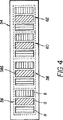
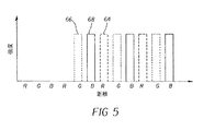
この方法は、入力データが空間的にオーバーラップする発光素子を有する表示装置のためにサンプリングされるときに3色のカラー入力信号を4色以上のカラー信号に変換する精度の高い方法を与えるが、入力信号がオーバーラップしない発光素子を有する表示装置上での表示のためにサンプリングされたときには、エッジに沿った色と輝度の分布が混乱する可能性がある。例えば3色カラー入力信号は、図4に示すようなピクセルパターン上にエッジを表示するように意図されることがある。この図は、各々が赤色R、緑色G、青色Bの発光素子の繰り返しパターンからなる4ピクセル(56、58、60、62)を含む表示装置54の一部を示す。これら4ピクセルは例えば、第2の緑色発光素子58Gに中心があるステップエッジを表示使用される可能性があり、その結果、図5に示すような各色に関する強度分布が得られる。
This method provides a highly accurate method for converting three color input signals into four or more color signals when input data is sampled for a display device having spatially overlapping light emitting elements. When the input signal is sampled for display on a display device having non-overlapping light emitting elements, the color and brightness distribution along the edge can be confused. For example, a three color input signal may be intended to display an edge on a pixel pattern as shown in FIG. This figure shows a portion of a display device 54 that includes four pixels (56, 58, 60, 62) each consisting of a repeating pattern of red R, green G, and blue B light emitting elements. For example, these four pixels may be used to display a step edge centered on the second green
図5は、図4の第2の緑色発光素子58G上に中心があるステップエッジに関する赤色64、緑色66、青色68の強度を示す。4色カラー変換アルゴリズムが適用されると、画像は図6に示すような4要素表示装置上に表示される。この図は、各々が赤色R、緑色G、青色B、白色Wの発光素子からなる4個のピクセル(72、74、76、78)を有する表示装置70を示す。図2に示すようなアルゴリズムが、図5に示すようなステップエッジを有し、図6に示す4色カラー表示装置70上に表示される3色カラー信号に適用されると、結果として得られる信号は図7に示すように現れるであろう。
FIG. 5 shows the intensities of red 64, green 66, and blue 68 for the step edge centered on the second green
図7に示すようにステップエッジの結果的に得られる画像は、第2のピクセル74内の緑色80、青色82信号と第3ピクセル76、第4ピクセル78内の白色84信号から構成されるであろう。ステップエッジが中立的な色になるように意図されているという事実にもかかわらず第2ピクセル74の色はシアンになることに注目すること。適当な解像度で、この結果的に得られる画像は、エッジの左側に沿ってシアン色の縞(フリンジ)とエッジの他端に赤色の縞(図示せず)とを持って現われるであろう。もし動画が表示されていれば、同様な現象が目に見える縞(フリンジ)またはジッター(ギザギザ)のエッジという結果をもたらす可能性がある。これらの問題を防止してエッジに沿った輝度分布を改善するために図2に示す方法は、前に計算28された共通信号Sの遷移を滑らかにするように修正され得る。
As shown in FIG. 7, the resulting image of the step edge is composed of the green 80 and blue 82 signals in the
本発明の方法を示す流れ図は、図8に示されている。この図に示すように共通信号は、複数のピクセルに関して計算される:86(図2に示すステップ22〜26)。それから重み付け平均への算入のために、隣接ピクセルが選択される:88。それから重み付け値が選択される:90。それからこの共通信号の重み付け平均は、現在ピクセルと一つ以上の隣接ピクセルとに関して計算される:92。好適には、この重み付け平均は、ピクセル56、58、60内の発光素子R、G、Bが互いに変位する方向に現在ピクセルの左に少なくとも一つのピクセルと、右に一つのピクセルとを含む隣接ピクセルから成るであろう。しかしながら、用語「隣接ピクセル」は、現在ピクセルのどちらかの側に2個以上のピクセルを含むこともあり得るが、また直角方向または斜め方向といった他の軸に沿って方向付けされたピクセルを含むこともある。例えば現在ピクセルのどちらかの側に共通信号Sまたは1ピクセルを使用すると、現在ピクセルcに関する最終共通信号S’を計算するために、方程式:
A flow diagram illustrating the method of the present invention is shown in FIG. As shown in this figure, the common signal is calculated for a plurality of pixels: 86 (steps 22-26 shown in FIG. 2). Then adjacent pixels are selected for inclusion in the weighted average: 88. A weighting value is then selected: 90. A weighted average of this common signal is then calculated for the current pixel and one or more neighboring pixels: 92. Preferably, this weighted average includes at least one pixel to the left of the current pixel and one pixel to the right in the direction in which the light emitting elements R, G, B in the
を使用することもあり得る。ここでS’はピクセルc−1、c、c+1からの共通信号Sの重み付け平均値であり、重み(w,w2,w3)は典型的にはIまで合計した定数であり、それぞれ0.25、0.5、0.25といった値を含むかもしれない。 May also be used. Here, S ′ is a weighted average value of the common signal S from the pixels c−1, c, and c + 1, and the weights (w, w2, w3) are typically constants totaled up to I, each of 0.25. , 0.5, 0.25, etc.
この例で論じられたような重みは定数であり得るが、重みはまた信号変化の方向に基づいて選択できる。例えば共通信号は、現在ピクセルのどちらかの側の一つ以上のピクセル間で比較され得る。それからこれら二つの信号のうちの小さい方が選択され、この小さい方の共通信号値に、大きい方の重み付け値が与えられる。 The weights as discussed in this example can be constant, but the weights can also be selected based on the direction of signal change. For example, the common signal can be compared between one or more pixels on either side of the current pixel. Then, the smaller one of these two signals is selected, and the smaller common signal value is given the larger weighting value.
それから任意選択的に、現在ピクセルcに関する元の共通信号Sと修正された共通信号S’とが比較され:94、そして前に計算された:26共通信号Sの代わりに使用されるために、これら二つの値のうちの最小値が選択される:96。いったん最終共通信号が計算されると、図2の残りのステップ(28〜42)は、この共通信号を使用して完了させられる:98。このアルゴリズムが0.25、0.5、0.25という一定の重みを想定している図5の3色カラー入力信号に適用されると、この結果として図9に示す信号が得られる。この図に示すように結果として得られる信号は、ピクセル76に関して赤色信号100、ピクセル74、76に関して緑色信号102、ピクセル74、76に関して青色信号104、ピクセル76、78に関して白色信号106を含む。ある赤色エネルギーがピクセル76に存在するので、ステップエッジの前部エッジに沿ったシアンの縞(フリンジ)は、視認性が減少する。したがってこの方法は、縞(フリンジ)の視認性を減少させる。更に動くエッジを示すとき発光素子間の移行は滑らかになり、エッジに沿ったジッターの出現は減少するであろう。
Then, optionally, the original common signal S and the modified common signal S ′ for the current pixel c are compared: 94, and previously calculated: 26 to be used instead of the common signal S The minimum of these two values is selected: 96. Once the final common signal is calculated, the remaining steps (28-42) of FIG. 2 are completed using this common signal: 98. When this algorithm is applied to the three-color input signal of FIG. 5 assuming constant weights of 0.25, 0.5, and 0.25, this results in the signal shown in FIG. As shown in this figure, the resulting signal includes a
代替の方法も案出可能である。例えば図8のステップ88〜96は、図10に示すステップで置き換えることができる。図10に示すように共通信号の最小値は、関連する隣接ピクセルに関して決定される:108。この最小値と現在ピクセルに関する共通信号とを使用して重み付け平均が計算される:110。最後に現在ピクセルに関する元の共通信号とステップ110で計算された値のうちの最小値が決定される112。前述の方法のようにこの方法は、エッジに沿った縞またはジッターの人為構成物の視認性を減少させる。図11は、ステップ110で等しい重みが適用されたときに結果として得られる信号を示す。もう一度、この信号は、ピクセル76に関して赤色信号114、ピクセル74、76に関して緑色信号116、ピクセル74、76に関して青色信号118、ピクセル76、78に関して白色信号120を含む。前と同様に、ピクセル76内の赤色信号114の存在は、ステップエッジに沿ったシアン縞の視認性を減少させる。
Alternative methods can be devised. For example, steps 88 to 96 in FIG. 8 can be replaced with the steps shown in FIG. As shown in FIG. 10, the minimum value of the common signal is determined for the associated neighboring pixel: 108. Using this minimum and the common signal for the current pixel, a weighted average is calculated: 110. Finally, the minimum of the original common signal for the current pixel and the value calculated in
この方法の単純化は、隣接ピクセルと現在ピクセルとに亘って前に計算28された最小共通信号を単純に計算して、この最小値を現在ピクセルに関する共通信号として適用することである。これは、関連する隣接ピクセルに関して決定108された最小信号に関して1.0である重みを重み付け平均ステップ110において適用することに相当する。
A simplification of this method is to simply calculate the minimum common signal previously calculated 28 over the neighboring pixel and the current pixel and apply this minimum value as the common signal for the current pixel. This corresponds to applying a weight in the
この方法はカラー縞および他の関連する撮像の人為構成物を減少させるという利点を有するが、この方法の主要な利点は品質の改善ではなく、このアルゴリズムが可能にする単純化された画像処理チェーン(連鎖)である。3色カラー入力信号の4色カラー信号への変換を含む典型的な画像処理チェーンは、図12に示されている。この図に示すように、高解像度3色カラー信号は、表示システムへの入力130であり得る。この信号は理想的には、3nが表示装置上の発光素子の数であるデータのn個のピクセルを表すであろう。それからこの信号は、3n個の信号値の各々に関して4色カラー信号に変換され:132、その結果として4n個の値になる。最後にこの信号は、各発光素子に関して1個のカラー値が存在するように、4n個の値から4/3n個の値にダウンサンプリングされる:134。
Although this method has the advantage of reducing color fringes and other related imaging artifacts, the main advantage of this method is not quality improvement, but a simplified image processing chain that this algorithm allows (Chain). A typical image processing chain involving the conversion of a three color input signal to a four color signal is shown in FIG. As shown in this figure, a high resolution three color signal may be an
処理ステップの数とこれらのステップを実行するために必要な処理パワーとを削減するために、ステップ132、134は理想的には、逆にされるであろう。しかしながら、図2に示す色変換処理が適用されると、カラー縞その他の関連人為構成物が結果として生じる可能性がある。しかしながら、共通信号が平滑化または最小化されると、ステップ132、134は、これらの人為構成物の存在なしに逆にできる。この場合、色変換処理132は、単にn個の信号値に関して実行されなくてはならないだけである。更にダウンサンプリングステップ134は、n個の信号値を4/3n個の値に減少させる。このように、必要な処理ステップを完了させるために、より低いパワーとより低いコストのプロセッサが適用できる。
In order to reduce the number of processing steps and the processing power required to perform these steps,
2 赤原色色度
4 緑原色色度
6 青原色色度
8 色域三角形
10 追加色域内原色色度
12 追加色域外原色色度
22 色域画定原色に関する入力信号
24 追加原色正規化信号計算ステップ
26 追加原色に正規化された信号
28 共通信号の関数F1計算ステップ
30 共通信号の関数F2計算ステップ
32 追加ステップ
34 追加原色に正規化された出力信号
36 白色点正規化信号計算ステップ
40 共通信号の関数F3計算ステップ
42 追加原色に関する出力信号
52 カーブのニー(ひざ状部)
54 表示装置
56 ピクセル
58 ピクセル
60 ピクセル
62 ピクセル
64 赤色強度
66 緑色強度
68 青色強度
70 表示装置
72 ピクセル
74 ピクセル
76 ピクセル
78 ピクセル
80 緑色信号
82 青色信号
84 白色信号
86 共通信号計算ステップ
88 ピクセル選択ステップ
90 重み付け値選択ステップ
94 比較ステップ
96 値選択ステップ
98 終了
100 赤色信号
102 緑色信号
104 青色信号
106 白色信号
108 共通信号決定ステップ
110 重み付け平均値計算ステップ
112 最小値決定ステップ
114 赤色信号
116 緑色信号
118 青色信号
120 白色信号
130 カラー信号入力ステップ
132 変換ステップ
134 ダウンサンプリングステップ
2 Red primary chromaticity 4 Green primary chromaticity 6 Blue
54
Claims (1)
a)現在ピクセルcと隣接ピクセルc−1、c+1とに関して関数F1を用いて3色カラー入力信号値(R,G,B)から負でない最小の信号値である共通信号値S(S(c−1),S(c),S(c+1))を計算するステップと、
b)前記現在ピクセルと隣接ピクセルとに関する共通信号値S(S(c−1),S(c),S(c+1))に基づいて最終共通信号値S’を決定するステップと、
c)前記最終共通信号値S’についての関数F2の値を計算して、これを前記3色カラー入力信号値(R,G,B)の各々に加算することによって前記3色カラー信号値(R’,G’,B’)を計算するステップと、
d)前記最終共通信号値S’についての関数F3として前記出力信号値Wを計算するステップと、を含み、
前記最終共通信号値S’を決定するステップは、
b1)前記隣接ピクセルc−1、c+1に関する3個の信号値(R,G,B)から負でない最小の信号値を選択して共通信号値S(c−1)、S(c+1)を決定するステップと、
b2)前記共通信号値S(c−1)、S(c+1)と前記現在ピクセルに関する共通信号値S(c)との重み付け平均値S’cを計算するステップと、
b3)前記重み付け平均値S’cと前記現在ピクセルに関する共通信号値S(c)との最小値として最終共通信号値S’を決定するステップと、
を含む方法。In order to drive a display device having a light emitter that emits light corresponding to a four-color output signal, a three-color input signal (R, G, B) corresponding to three gamut-defining primaries is applied to the color. A method for converting into four color output signals (R ′, G ′, B ′, W) corresponding to a region defining primary color and one additional primary color W,
a) The common signal value S (S (c ) which is the smallest non-negative signal value from the three color input signal values (R, G, B) using the function F1 with respect to the current pixel c and the adjacent pixels c-1, c + 1. -1), S (c), S (c + 1)) ;
b) determining a final common signal value S ′ based on the common signal values S (S (c−1), S (c), S (c + 1)) for the current pixel and adjacent pixels;
c) calculating the value of the function F2 for the final common signal value S ′ and adding it to each of the three color input signal values (R, G, B), thereby obtaining the three color signal value ( Calculating R ′, G ′, B ′);
d) calculating the output signal value W as a function F3 for the final common signal value S ′ ;
Determining the final common signal value S ′ comprises:
b1) The common signal values S (c-1) and S (c + 1) are determined by selecting the smallest non-negative signal value from the three signal values (R, G, B) for the adjacent pixels c-1, c + 1. And steps to
b2) calculating a weighted average value S′c of the common signal values S (c−1), S (c + 1) and the common signal value S (c) for the current pixel;
b3) determining a final common signal value S ′ as a minimum value of the weighted average value S′c and the common signal value S (c) for the current pixel;
Including methods.
Applications Claiming Priority (3)
| Application Number | Priority Date | Filing Date | Title |
|---|---|---|---|
| US10/703,748 US6885380B1 (en) | 2003-11-07 | 2003-11-07 | Method for transforming three colors input signals to four or more output signals for a color display |
| US10/703,748 | 2003-11-07 | ||
| PCT/US2004/037118 WO2005048232A1 (en) | 2003-11-07 | 2004-11-05 | Method for transforming three colour input signals to more colour signals |
Publications (3)
| Publication Number | Publication Date |
|---|---|
| JP2007514184A JP2007514184A (en) | 2007-05-31 |
| JP2007514184A5 JP2007514184A5 (en) | 2007-11-08 |
| JP4745977B2 true JP4745977B2 (en) | 2011-08-10 |
Family
ID=34435580
Family Applications (1)
| Application Number | Title | Priority Date | Filing Date |
|---|---|---|---|
| JP2006538536A Expired - Lifetime JP4745977B2 (en) | 2003-11-07 | 2004-11-05 | Method for converting a three-color input signal into a larger number of color signals |
Country Status (5)
| Country | Link |
|---|---|
| US (1) | US6885380B1 (en) |
| JP (1) | JP4745977B2 (en) |
| KR (1) | KR101049051B1 (en) |
| CN (1) | CN100505001C (en) |
| WO (1) | WO2005048232A1 (en) |
Families Citing this family (115)
| Publication number | Priority date | Publication date | Assignee | Title |
|---|---|---|---|---|
| US8022969B2 (en) * | 2001-05-09 | 2011-09-20 | Samsung Electronics Co., Ltd. | Rotatable display with sub-pixel rendering |
| US7307646B2 (en) * | 2001-05-09 | 2007-12-11 | Clairvoyante, Inc | Color display pixel arrangements and addressing means |
| US7221381B2 (en) * | 2001-05-09 | 2007-05-22 | Clairvoyante, Inc | Methods and systems for sub-pixel rendering with gamma adjustment |
| US7123277B2 (en) * | 2001-05-09 | 2006-10-17 | Clairvoyante, Inc. | Conversion of a sub-pixel format data to another sub-pixel data format |
| US7184066B2 (en) | 2001-05-09 | 2007-02-27 | Clairvoyante, Inc | Methods and systems for sub-pixel rendering with adaptive filtering |
| US20030117423A1 (en) * | 2001-12-14 | 2003-06-26 | Brown Elliott Candice Hellen | Color flat panel display sub-pixel arrangements and layouts with reduced blue luminance well visibility |
| WO2003053068A2 (en) | 2001-12-14 | 2003-06-26 | Clairvoyante Laboratories, Inc. | Improvements to color flat panel display sub-pixel arrangements and layouts with reduced visibility of a blue luminance well |
| US7755652B2 (en) * | 2002-01-07 | 2010-07-13 | Samsung Electronics Co., Ltd. | Color flat panel display sub-pixel rendering and driver configuration for sub-pixel arrangements with split sub-pixels |
| US7417648B2 (en) | 2002-01-07 | 2008-08-26 | Samsung Electronics Co. Ltd., | Color flat panel display sub-pixel arrangements and layouts for sub-pixel rendering with split blue sub-pixels |
| US7492379B2 (en) * | 2002-01-07 | 2009-02-17 | Samsung Electronics Co., Ltd. | Color flat panel display sub-pixel arrangements and layouts for sub-pixel rendering with increased modulation transfer function response |
| US7365722B2 (en) * | 2002-09-11 | 2008-04-29 | Samsung Electronics Co., Ltd. | Four color liquid crystal display and driving device and method thereof |
| US7046256B2 (en) * | 2003-01-22 | 2006-05-16 | Clairvoyante, Inc | System and methods of subpixel rendering implemented on display panels |
| US20040196302A1 (en) * | 2003-03-04 | 2004-10-07 | Im Moon Hwan | Systems and methods for temporal subpixel rendering of image data |
| US7352374B2 (en) * | 2003-04-07 | 2008-04-01 | Clairvoyante, Inc | Image data set with embedded pre-subpixel rendered image |
| US20040233308A1 (en) * | 2003-05-20 | 2004-11-25 | Elliott Candice Hellen Brown | Image capture device and camera |
| US7230584B2 (en) * | 2003-05-20 | 2007-06-12 | Clairvoyante, Inc | Projector systems with reduced flicker |
| US7268748B2 (en) * | 2003-05-20 | 2007-09-11 | Clairvoyante, Inc | Subpixel rendering for cathode ray tube devices |
| US7187353B2 (en) * | 2003-06-06 | 2007-03-06 | Clairvoyante, Inc | Dot inversion on novel display panel layouts with extra drivers |
| US20040246280A1 (en) * | 2003-06-06 | 2004-12-09 | Credelle Thomas Lloyd | Image degradation correction in novel liquid crystal displays |
| US7397455B2 (en) * | 2003-06-06 | 2008-07-08 | Samsung Electronics Co., Ltd. | Liquid crystal display backplane layouts and addressing for non-standard subpixel arrangements |
| US7209105B2 (en) * | 2003-06-06 | 2007-04-24 | Clairvoyante, Inc | System and method for compensating for visual effects upon panels having fixed pattern noise with reduced quantization error |
| US8035599B2 (en) | 2003-06-06 | 2011-10-11 | Samsung Electronics Co., Ltd. | Display panel having crossover connections effecting dot inversion |
| US7598961B2 (en) * | 2003-10-21 | 2009-10-06 | Samsung Electronics Co., Ltd. | method and apparatus for converting from a source color space to a target color space |
| US7728846B2 (en) * | 2003-10-21 | 2010-06-01 | Samsung Electronics Co., Ltd. | Method and apparatus for converting from source color space to RGBW target color space |
| US7525526B2 (en) * | 2003-10-28 | 2009-04-28 | Samsung Electronics Co., Ltd. | System and method for performing image reconstruction and subpixel rendering to effect scaling for multi-mode display |
| US7084923B2 (en) * | 2003-10-28 | 2006-08-01 | Clairvoyante, Inc | Display system having improved multiple modes for displaying image data from multiple input source formats |
| KR101058456B1 (en) * | 2003-12-29 | 2011-08-24 | 엘지디스플레이 주식회사 | Display and its driving method |
| KR20050072505A (en) * | 2004-01-06 | 2005-07-12 | 삼성전자주식회사 | Apparatus and method of converting image signal for four color display device |
| US7248268B2 (en) * | 2004-04-09 | 2007-07-24 | Clairvoyante, Inc | Subpixel rendering filters for high brightness subpixel layouts |
| US7301543B2 (en) * | 2004-04-09 | 2007-11-27 | Clairvoyante, Inc. | Systems and methods for selecting a white point for image displays |
| US7619637B2 (en) * | 2004-04-09 | 2009-11-17 | Samsung Electronics Co., Ltd. | Systems and methods for improved gamut mapping from one image data set to another |
| KR101090247B1 (en) * | 2004-04-19 | 2011-12-06 | 삼성전자주식회사 | Driving apparatus and method of four-color display device |
| US7590299B2 (en) * | 2004-06-10 | 2009-09-15 | Samsung Electronics Co., Ltd. | Increasing gamma accuracy in quantized systems |
| TW200623001A (en) * | 2004-12-31 | 2006-07-01 | Wintek Corp | Image-processing device and method for enhancing the luminance and the image quality of display panels |
| CN101156455B (en) * | 2005-04-04 | 2011-07-06 | 皇家飞利浦电子股份有限公司 | Method of converting signals for multi-primary displays |
| KR101229886B1 (en) * | 2005-04-04 | 2013-02-07 | 삼성디스플레이 주식회사 | Systems and methods for implementing low cost gamut mapping algorithms |
| CN1882103B (en) * | 2005-04-04 | 2010-06-23 | 三星电子株式会社 | Systems and methods for implementing improved gamut mapping algorithms |
| CN101164096B (en) * | 2005-04-21 | 2011-07-06 | 皇家飞利浦电子股份有限公司 | Method for converting three-primary-color input signal into N-primary-color driving signal |
| WO2006111897A1 (en) * | 2005-04-21 | 2006-10-26 | Koninklijke Philips Electronics N.V. | Converting a three primary color input signal into four drive signals |
| CN101164099B (en) * | 2005-04-21 | 2012-06-20 | 皇家飞利浦电子股份有限公司 | Redistribution of n-primary color input signals into n-primary color output signals |
| EP1758092A1 (en) * | 2005-08-22 | 2007-02-28 | Koninklijke Philips Electronics N.V. | Converting a three-primary input color signal into an N-primary color drive signal |
| EP1752963A1 (en) * | 2005-08-09 | 2007-02-14 | Koninklijke Philips Electronics N.V. | Sub-pixel mapping |
| EP1752962A1 (en) * | 2005-08-09 | 2007-02-14 | Koninklijke Philips Electronics N.V. | Redistribution of N-primary color input signals into N-primary color output signals |
| JP5070204B2 (en) | 2005-05-20 | 2012-11-07 | サムスン エレクトロニクス カンパニー リミテッド | Multiple primary color sub-pixel rendering with metamer filtering |
| TW200643848A (en) * | 2005-06-01 | 2006-12-16 | Wintek Corp | Method and apparatus for four-color data conversion |
| US7636076B2 (en) * | 2005-09-22 | 2009-12-22 | Au Optronics Corporation | Four-color transflective color liquid crystal display |
| JP5063607B2 (en) * | 2005-11-09 | 2012-10-31 | 奇美電子股▲ふん▼有限公司 | Method and apparatus for processing pixel signals for driving a display, and display using the signals |
| JP5191632B2 (en) * | 2005-11-29 | 2013-05-08 | 京セラ株式会社 | Image display device and image display method |
| US7742205B2 (en) * | 2005-12-16 | 2010-06-22 | Vp Assets Limited Registered In British Virgin Islands | Perceptual color matching method between two different polychromatic displays |
| US7586497B2 (en) | 2005-12-20 | 2009-09-08 | Eastman Kodak Company | OLED display with improved power performance |
| US7710022B2 (en) * | 2006-01-27 | 2010-05-04 | Global Oled Technology Llc | EL device having improved power distribution |
| US7791621B2 (en) * | 2006-04-18 | 2010-09-07 | Toppoly Optoelectronics Corp. | Systems and methods for providing driving voltages to RGBW display panels |
| US7965305B2 (en) * | 2006-05-08 | 2011-06-21 | Global Oled Technology Llc | Color display system with improved apparent resolution |
| US7969428B2 (en) * | 2006-05-08 | 2011-06-28 | Global Oled Technology Llc | Color display system with improved apparent resolution |
| US20070257866A1 (en) * | 2006-05-08 | 2007-11-08 | Eastman Kodak Company | Method and apparatus for defect correction in a display |
| US20070257945A1 (en) * | 2006-05-08 | 2007-11-08 | Eastman Kodak Company | Color EL display system with improved resolution |
| US20070257943A1 (en) * | 2006-05-08 | 2007-11-08 | Eastman Kodak Company | Method for rendering color EL display and display device with improved resolution |
| US7592996B2 (en) * | 2006-06-02 | 2009-09-22 | Samsung Electronics Co., Ltd. | Multiprimary color display with dynamic gamut mapping |
| KR20080009497A (en) * | 2006-07-24 | 2008-01-29 | 삼성전자주식회사 | Multicolor display device and its driving method |
| US8018476B2 (en) | 2006-08-28 | 2011-09-13 | Samsung Electronics Co., Ltd. | Subpixel layouts for high brightness displays and systems |
| US7876341B2 (en) * | 2006-08-28 | 2011-01-25 | Samsung Electronics Co., Ltd. | Subpixel layouts for high brightness displays and systems |
| WO2008039764A2 (en) * | 2006-09-30 | 2008-04-03 | Clairvoyante, Inc. | Systems and methods for reducing desaturation of images rendered on high brightness displays |
| US8525444B2 (en) * | 2006-12-20 | 2013-09-03 | Koninklijke Philips N.V. | Lighting device with multiple primary colors |
| KR101329125B1 (en) * | 2007-08-13 | 2013-11-14 | 삼성전자주식회사 | RV-to-RGBW color separation method and system |
| FR2921785A1 (en) * | 2007-10-01 | 2009-04-03 | Thomson Licensing Sas | SYSTEM FOR DISPLAYING IMAGES WITH FOUR PRIMARY COLORS FROM VIDEO DATA BASED ON THREE PRIMARY COLORS. |
| KR101273468B1 (en) | 2007-10-01 | 2013-06-14 | 삼성전자주식회사 | System and method for convert rgb to rgbw color using white value extraction |
| JP4683343B2 (en) * | 2007-12-27 | 2011-05-18 | 株式会社 日立ディスプレイズ | Color signal generator |
| CN101489143B (en) * | 2008-01-14 | 2010-12-08 | 胜华科技股份有限公司 | Image processing method, image data conversion method and device |
| JP5326485B2 (en) * | 2008-10-17 | 2013-10-30 | カシオ計算機株式会社 | Display device and display method thereof |
| JP5619429B2 (en) * | 2010-01-28 | 2014-11-05 | 株式会社ジャパンディスプレイ | Driving method of image display device and driving method of image display device assembly |
| JP4861523B2 (en) * | 2010-03-15 | 2012-01-25 | シャープ株式会社 | Display device and television receiver |
| US8619103B2 (en) | 2011-01-31 | 2013-12-31 | Global Oled Technology Llc | Electroluminescent device multilevel-drive chromaticity-shift compensation |
| US8456390B2 (en) | 2011-01-31 | 2013-06-04 | Global Oled Technology Llc | Electroluminescent device aging compensation with multilevel drive |
| CN102243828A (en) * | 2011-06-17 | 2011-11-16 | 深圳晶为华悦科技有限公司 | Color display screen and display method thereof |
| US9165526B2 (en) * | 2012-02-28 | 2015-10-20 | Shenzhen Yunyinggu Technology Co., Ltd. | Subpixel arrangements of displays and method for rendering the same |
| US9401012B2 (en) * | 2012-10-18 | 2016-07-26 | Athentech Technologies Inc. | Method for correcting purple distortion in digital images and a computing device employing same |
| DE102013108552B4 (en) * | 2013-08-08 | 2016-07-21 | Insta Elektro Gmbh | Control method for a mixed light source and control device for a mixed light source |
| JP6514482B2 (en) | 2013-10-22 | 2019-05-15 | 株式会社ジャパンディスプレイ | Display device and color conversion method |
| JP6389728B2 (en) | 2013-10-22 | 2018-09-12 | 株式会社ジャパンディスプレイ | Display device and color conversion method |
| JP6389729B2 (en) | 2013-10-22 | 2018-09-12 | 株式会社ジャパンディスプレイ | Display device and color conversion method |
| JP6533656B2 (en) | 2013-10-22 | 2019-06-19 | 株式会社ジャパンディスプレイ | Image processing apparatus, image display apparatus, electronic apparatus, and image processing method |
| JP6395434B2 (en) * | 2014-05-15 | 2018-09-26 | 株式会社ジャパンディスプレイ | Display device, display device driving method, and electronic apparatus |
| JP5784797B2 (en) * | 2014-06-17 | 2015-09-24 | 株式会社ジャパンディスプレイ | Driving method of image display device and driving method of image display device assembly |
| JP2016014727A (en) | 2014-07-01 | 2016-01-28 | 株式会社ジャパンディスプレイ | Display device, electronic device, and image display method |
| JP2016024276A (en) | 2014-07-17 | 2016-02-08 | 株式会社ジャパンディスプレイ | Display device |
| US9280940B2 (en) * | 2014-07-17 | 2016-03-08 | Shenzhen China Star Optoelectronics Technology Co., Ltd. | Liquid crystal display device, four-color converter, and conversion method for converting RGB data to RGBW data |
| JP6504798B2 (en) | 2014-11-26 | 2019-04-24 | 株式会社ジャパンディスプレイ | Display device and color conversion method |
| JP6514495B2 (en) * | 2014-12-03 | 2019-05-15 | 株式会社ジャパンディスプレイ | Image display device |
| CN104732909A (en) * | 2015-04-09 | 2015-06-24 | 京东方科技集团股份有限公司 | Image conversion method, signal source device and display driving device |
| BR112018075903A2 (en) | 2016-06-22 | 2019-03-19 | Dolby Laboratories Licensing Corp | Wide color gamut two-dimensional (2d) image rendering on three-dimensional (3d) displays |
| US10490130B2 (en) | 2017-02-10 | 2019-11-26 | Semiconductor Energy Laboratory Co., Ltd. | Display system comprising controller which process data |
| CN108172198A (en) | 2018-01-02 | 2018-06-15 | 京东方科技集团股份有限公司 | Image processing apparatus, storage medium, display equipment and image processing method |
| CN108877693A (en) * | 2018-07-23 | 2018-11-23 | 东南大学 | A kind of four sequential liquid crystal display control methods |
| US11475819B2 (en) | 2018-10-25 | 2022-10-18 | Baylor University | System and method for a multi-primary wide gamut color system |
| US11043157B2 (en) | 2018-10-25 | 2021-06-22 | Baylor University | System and method for a six-primary wide gamut color system |
| US10607527B1 (en) | 2018-10-25 | 2020-03-31 | Baylor University | System and method for a six-primary wide gamut color system |
| US11373575B2 (en) | 2018-10-25 | 2022-06-28 | Baylor University | System and method for a multi-primary wide gamut color system |
| US11341890B2 (en) | 2018-10-25 | 2022-05-24 | Baylor University | System and method for a multi-primary wide gamut color system |
| US11069280B2 (en) | 2018-10-25 | 2021-07-20 | Baylor University | System and method for a multi-primary wide gamut color system |
| US11289000B2 (en) | 2018-10-25 | 2022-03-29 | Baylor University | System and method for a multi-primary wide gamut color system |
| US11289003B2 (en) | 2018-10-25 | 2022-03-29 | Baylor University | System and method for a multi-primary wide gamut color system |
| US11069279B2 (en) | 2018-10-25 | 2021-07-20 | Baylor University | System and method for a multi-primary wide gamut color system |
| US11488510B2 (en) | 2018-10-25 | 2022-11-01 | Baylor University | System and method for a multi-primary wide gamut color system |
| US10997896B2 (en) | 2018-10-25 | 2021-05-04 | Baylor University | System and method for a six-primary wide gamut color system |
| US11532261B1 (en) | 2018-10-25 | 2022-12-20 | Baylor University | System and method for a multi-primary wide gamut color system |
| US11062638B2 (en) | 2018-10-25 | 2021-07-13 | Baylor University | System and method for a multi-primary wide gamut color system |
| US11037481B1 (en) | 2018-10-25 | 2021-06-15 | Baylor University | System and method for a multi-primary wide gamut color system |
| US11403987B2 (en) | 2018-10-25 | 2022-08-02 | Baylor University | System and method for a multi-primary wide gamut color system |
| US11189210B2 (en) | 2018-10-25 | 2021-11-30 | Baylor University | System and method for a multi-primary wide gamut color system |
| US11410593B2 (en) | 2018-10-25 | 2022-08-09 | Baylor University | System and method for a multi-primary wide gamut color system |
| US10950161B2 (en) | 2018-10-25 | 2021-03-16 | Baylor University | System and method for a six-primary wide gamut color system |
| US11030934B2 (en) | 2018-10-25 | 2021-06-08 | Baylor University | System and method for a multi-primary wide gamut color system |
| US10950162B2 (en) | 2018-10-25 | 2021-03-16 | Baylor University | System and method for a six-primary wide gamut color system |
| US11587491B1 (en) | 2018-10-25 | 2023-02-21 | Baylor University | System and method for a multi-primary wide gamut color system |
| US11315467B1 (en) | 2018-10-25 | 2022-04-26 | Baylor University | System and method for a multi-primary wide gamut color system |
Citations (1)
| Publication number | Priority date | Publication date | Assignee | Title |
|---|---|---|---|---|
| US20020122160A1 (en) * | 2000-12-30 | 2002-09-05 | Kunzman Adam J. | Reduced color separation white enhancement for sequential color displays |
Family Cites Families (8)
| Publication number | Priority date | Publication date | Assignee | Title |
|---|---|---|---|---|
| US5341153A (en) * | 1988-06-13 | 1994-08-23 | International Business Machines Corporation | Method of and apparatus for displaying a multicolor image |
| JPH05241551A (en) * | 1991-11-07 | 1993-09-21 | Canon Inc | Image processor |
| US6453067B1 (en) * | 1997-10-20 | 2002-09-17 | Texas Instruments Incorporated | Brightness gain using white segment with hue and gain correction |
| US6594387B1 (en) * | 1999-04-30 | 2003-07-15 | Texas Instruments Incorporated | Enhanced color correction |
| US7123277B2 (en) * | 2001-05-09 | 2006-10-17 | Clairvoyante, Inc. | Conversion of a sub-pixel format data to another sub-pixel data format |
| US7436996B2 (en) * | 2001-06-07 | 2008-10-14 | Genoa Color Technologies Ltd | Device, system and method of data conversion for wide gamut displays |
| EP1388818B1 (en) * | 2002-08-10 | 2011-06-22 | Samsung Electronics Co., Ltd. | Method and apparatus for rendering image signal |
| US7184067B2 (en) * | 2003-03-13 | 2007-02-27 | Eastman Kodak Company | Color OLED display system |
-
2003
- 2003-11-07 US US10/703,748 patent/US6885380B1/en not_active Expired - Lifetime
-
2004
- 2004-11-05 KR KR1020067010750A patent/KR101049051B1/en active IP Right Grant
- 2004-11-05 JP JP2006538536A patent/JP4745977B2/en not_active Expired - Lifetime
- 2004-11-05 CN CNB2004800324414A patent/CN100505001C/en not_active Expired - Lifetime
- 2004-11-05 WO PCT/US2004/037118 patent/WO2005048232A1/en active Application Filing
Patent Citations (1)
| Publication number | Priority date | Publication date | Assignee | Title |
|---|---|---|---|---|
| US20020122160A1 (en) * | 2000-12-30 | 2002-09-05 | Kunzman Adam J. | Reduced color separation white enhancement for sequential color displays |
Also Published As
| Publication number | Publication date |
|---|---|
| CN1875396A (en) | 2006-12-06 |
| JP2007514184A (en) | 2007-05-31 |
| KR20060122882A (en) | 2006-11-30 |
| US6885380B1 (en) | 2005-04-26 |
| KR101049051B1 (en) | 2011-07-15 |
| US20050099426A1 (en) | 2005-05-12 |
| CN100505001C (en) | 2009-06-24 |
| WO2005048232A1 (en) | 2005-05-26 |
Similar Documents
| Publication | Publication Date | Title |
|---|---|---|
| JP4745977B2 (en) | Method for converting a three-color input signal into a larger number of color signals | |
| EP1636788B1 (en) | Transforming three color input signals to more color signals | |
| EP2135461B1 (en) | Input-signal transformation for rgbw displays | |
| JP4241902B2 (en) | Color image display device and color conversion device | |
| US8094933B2 (en) | Method for converting an input color signal | |
| JP4705917B2 (en) | Method and apparatus for converting from a source color space to a target color space | |
| US8194019B2 (en) | Color signal converter, display unit, color signal conversion program, computer-readable storage medium storing color signal conversion program, and color signal conversion method | |
| US8184112B2 (en) | Increasing dynamic range of display output | |
| KR101348369B1 (en) | Color conversion method and apparatus for display device | |
| US20080198180A1 (en) | Method and Apparatus of Converting Signals for Driving Display and a Display Using the Same | |
| CN103761955B (en) | Perceptual color matching method between two different multicolor displays | |
| JP4950846B2 (en) | Color image display device and color conversion device | |
| KR20090079949A (en) | Gamut mapping | |
| US6774953B2 (en) | Method and apparatus for color warping | |
| US7719715B2 (en) | Tone characteristics-conversion determining apparatus, tone characteristics-conversion determining method, tone characteristics-conversion determining program, image processing apparatus, and image display apparatus | |
| Miller et al. | RGB‐to‐RGBW conversion with current limiting for OLED displays | |
| JP3568367B2 (en) | Display device |
Legal Events
| Date | Code | Title | Description |
|---|---|---|---|
| A521 | Request for written amendment filed |
Free format text: JAPANESE INTERMEDIATE CODE: A523 Effective date: 20070921 |
|
| A621 | Written request for application examination |
Free format text: JAPANESE INTERMEDIATE CODE: A621 Effective date: 20070921 |
|
| A711 | Notification of change in applicant |
Free format text: JAPANESE INTERMEDIATE CODE: A711 Effective date: 20100803 |
|
| A131 | Notification of reasons for refusal |
Free format text: JAPANESE INTERMEDIATE CODE: A131 Effective date: 20101109 |
|
| A521 | Request for written amendment filed |
Free format text: JAPANESE INTERMEDIATE CODE: A523 Effective date: 20110209 |
|
| TRDD | Decision of grant or rejection written | ||
| A01 | Written decision to grant a patent or to grant a registration (utility model) |
Free format text: JAPANESE INTERMEDIATE CODE: A01 Effective date: 20110412 |
|
| A61 | First payment of annual fees (during grant procedure) |
Free format text: JAPANESE INTERMEDIATE CODE: A61 Effective date: 20110512 |
|
| FPAY | Renewal fee payment (event date is renewal date of database) |
Free format text: PAYMENT UNTIL: 20140520 Year of fee payment: 3 |
|
| R150 | Certificate of patent or registration of utility model |
Ref document number: 4745977 Country of ref document: JP Free format text: JAPANESE INTERMEDIATE CODE: R150 Free format text: JAPANESE INTERMEDIATE CODE: R150 |
|
| R250 | Receipt of annual fees |
Free format text: JAPANESE INTERMEDIATE CODE: R250 |
|
| R250 | Receipt of annual fees |
Free format text: JAPANESE INTERMEDIATE CODE: R250 |
|
| R250 | Receipt of annual fees |
Free format text: JAPANESE INTERMEDIATE CODE: R250 |
|
| R250 | Receipt of annual fees |
Free format text: JAPANESE INTERMEDIATE CODE: R250 |
|
| R250 | Receipt of annual fees |
Free format text: JAPANESE INTERMEDIATE CODE: R250 |
|
| R250 | Receipt of annual fees |
Free format text: JAPANESE INTERMEDIATE CODE: R250 |
|
| R250 | Receipt of annual fees |
Free format text: JAPANESE INTERMEDIATE CODE: R250 |
|
| R250 | Receipt of annual fees |
Free format text: JAPANESE INTERMEDIATE CODE: R250 |
|
| R250 | Receipt of annual fees |
Free format text: JAPANESE INTERMEDIATE CODE: R250 |
|
| R250 | Receipt of annual fees |
Free format text: JAPANESE INTERMEDIATE CODE: R250 |
|
| R250 | Receipt of annual fees |
Free format text: JAPANESE INTERMEDIATE CODE: R250 |
|
| EXPY | Cancellation because of completion of term |