JP4745587B2 - Toothed belt pulley with flange - Google Patents
Toothed belt pulley with flange Download PDFInfo
- Publication number
- JP4745587B2 JP4745587B2 JP2001578846A JP2001578846A JP4745587B2 JP 4745587 B2 JP4745587 B2 JP 4745587B2 JP 2001578846 A JP2001578846 A JP 2001578846A JP 2001578846 A JP2001578846 A JP 2001578846A JP 4745587 B2 JP4745587 B2 JP 4745587B2
- Authority
- JP
- Japan
- Prior art keywords
- pulley
- toothed belt
- belt pulley
- flange portion
- belt
- Prior art date
- Legal status (The legal status is an assumption and is not a legal conclusion. Google has not performed a legal analysis and makes no representation as to the accuracy of the status listed.)
- Expired - Fee Related
Links
Images


Classifications
-
- F—MECHANICAL ENGINEERING; LIGHTING; HEATING; WEAPONS; BLASTING
- F16—ENGINEERING ELEMENTS AND UNITS; GENERAL MEASURES FOR PRODUCING AND MAINTAINING EFFECTIVE FUNCTIONING OF MACHINES OR INSTALLATIONS; THERMAL INSULATION IN GENERAL
- F16H—GEARING
- F16H55/00—Elements with teeth or friction surfaces for conveying motion; Worms, pulleys or sheaves for gearing mechanisms
- F16H55/02—Toothed members; Worms
- F16H55/17—Toothed wheels
- F16H55/171—Toothed belt pulleys
-
- F—MECHANICAL ENGINEERING; LIGHTING; HEATING; WEAPONS; BLASTING
- F16—ENGINEERING ELEMENTS AND UNITS; GENERAL MEASURES FOR PRODUCING AND MAINTAINING EFFECTIVE FUNCTIONING OF MACHINES OR INSTALLATIONS; THERMAL INSULATION IN GENERAL
- F16H—GEARING
- F16H7/00—Gearings for conveying rotary motion by endless flexible members
- F16H7/02—Gearings for conveying rotary motion by endless flexible members with belts; with V-belts
- F16H7/023—Gearings for conveying rotary motion by endless flexible members with belts; with V-belts with belts having a toothed contact surface or regularly spaced bosses or hollows for slipless or nearly slipless meshing with complementary profiled contact surface of a pulley
-
- Y—GENERAL TAGGING OF NEW TECHNOLOGICAL DEVELOPMENTS; GENERAL TAGGING OF CROSS-SECTIONAL TECHNOLOGIES SPANNING OVER SEVERAL SECTIONS OF THE IPC; TECHNICAL SUBJECTS COVERED BY FORMER USPC CROSS-REFERENCE ART COLLECTIONS [XRACs] AND DIGESTS
- Y10—TECHNICAL SUBJECTS COVERED BY FORMER USPC
- Y10T—TECHNICAL SUBJECTS COVERED BY FORMER US CLASSIFICATION
- Y10T29/00—Metal working
- Y10T29/49—Method of mechanical manufacture
- Y10T29/49453—Pulley making
Abstract
Description
【0001】
本発明は、少なくとも1つのフランジを有するとともに1つ以上の歯付ベルトと係合する歯状円周面を有する歯付ベルトプーリに関する。加えて、本発明は、複数のこのような歯付ベルトプーリを有する歯付ベルトプーリシステムに関する。
【0002】
歯付ベルトプーリシステムは、全ての組み合わされた回転軸を駆動するのに1つのモータで十分であるように、歯付ベルトによって複数の離隔した回転軸を組合わせるための装置に使用される。3つ以上の回転軸の駆動は、対応する数の歯付ベルトプーリへ前述のベルトを案内することにより、1つの歯付ベルトによって保証することができる。しかし、回転軸対に別体の歯付ベルトを設けることもできる(縦列配置(cascade arrangement)。
【0003】
作動中に、特にベルトが歯付ベルトプーリから横に滑り落ちるのを阻止するためのフランジが、歯付ベルトプーリの一面或いは両面に配置されたフランジの付いたホイールによって通常、形成される。
【0004】
しかし、フランジの付いたホイールの存在によって、歯付ベルトの取付および交換の際に問題が起こる。装着されたベルトは、高負荷および高速で運転したときでも、プーリとの信頼できる係合を保証するために少なくとも僅かな予荷重を必要とするので、既に組み立てられた歯付ベルトプーリに、ベルトをフランジ付きのホイールを越えて簡単に配置することは容易ではない。この問題は、プーリにベルトを配置した後にのみフランジの付いたホイールを配置するか、或いは、プーリを作動位置に旋回してベルトを取り付けた後にのみそれをロックするか、或いは、過度に長いベルトを使用して、取付後に別体の張力ローラによってそれに予荷重をかけることによってのみ回避できる。しかしながら、これらの解決策は、相当な構造上の試みを必要とする。
【0005】
特に、多数の回転軸が、複数の歯付ベルトを介して縦列に組み合わされている紙幣処理機のような比較的複雑な装置では、装置の構造的な試みや、ベルトを交換する際の保守の苦労は非常に大きいものとなる。
【0006】
従って、本発明の課題は、ベルトを簡単に装着することを可能にするとともに、運転中にベルトが滑って外れることを確実に阻止する歯付ベルトプーリおよび歯付ベルトプーリシステムを提案することである。
【0007】
この課題は、独立請求項の歯付ベルトプーリおよび歯付ベルトプーリシステムを使用して本発明により解決される。
【0008】
本発明の好ましい実施の形態は、従属請求項に記載されている。
【0009】
課題を解決するために、運転中にベルトが滑って外れるのを防止するためのフランジを、プーリの円周の限定した部分に亘ってのみフランジ部として形成することが提案されている。組み合わされる2つの回転軸のプーリが互いに関連して回転すると、プーリの円周を越えて突出した特定のフランジ部が互いに向き合い、ベルトは、フランジ部と衝接することなく、フランジ部を越えて2つのプーリに取り付けることが可能となる。
【0010】
これは、ベルトが取り付けられるときに、フランジ部が、完全にベルトの内部領域内にある、即ち負荷ストランド(load strand)と戻りストランド(return strand)の間にあるように、プーリの円周方向におけるフランジ部の長さが選択されることが前提である。プーリの周りのベルトの所定の巻角aで、フランジ部はプーリの円周方向に、ベルトが取り付けられるときに衝接することなく360°−aの逃げ角に亘って延びることができる。しかし、フランジ部の局部的な半径方向の高さは、ベルトの接線方向(tangential course)に適応することが留意されねばならない。同様に大きいプーリが、例えば、ローラトラック(roller track)の駆動部と関連して組み合わされる場合は、フランジ部は、プーリの円周の180°より僅かに小さい範囲に亘って延出すべきである。しかし、組み合わされるべき2つのプーリの直径が異なっている(増加或いは減少(multoplication or reduction))ならば、大きい方のプーリのフランジ部は、小さい方のプーリ(例えば220°)のフランジ部より、少ない円周角(例えば140°)に亘って延出する。
【0011】
本発明は、このように、全てのプーリを予め組み立てることができ、そして、保守の際に、ベルト或いはベルト類が取り付けられるか、或いは交換されるとき、その方法を維持することができるという本質的な利点を提供する。
【0012】
1つのモータによって駆動される、縦列配置された多数の回転軸を有する比較的複雑な装置の場合、2つの軸が同時に別体の歯付きベルトによってこのように組み合わされ、ベルトの取付は、関連する回転軸を回転させて2つのプーリのフランジ部を互いに反対位置とし、そして、フランジ部を通過してベルトをプーリに押圧することにより簡単になされる。この方法で、ベルトを完全に縦列に首尾よく取り付けることができる。
【0013】
ベルトが縦列の場合、少なくとも2つのベルトが、各場合につき、縦列の中間の軸で作動する。このような場合、円周方向に互いに120°位置のずれた3つのフランジ部、即ち、2つのベルトの間の1つのフランジ部およびベルトの各側に1つのフランジ部が形成されたら有利である。関連する軸が120°回転すると、上記の方法でプーリに押されたベルトは、さらに押されて中間のフランジ部を越えて後部位置、即ち後部プーリに入ることが可能となる。
【0014】
3つ以上のベルトも1つの軸に走らせることができ、それに応じて、円周に均等に配分された、さらに多いフランジ部が設けられねばならない。ベルトがn個の場合、円周方向に互いに360°/n或いは360°/(n+1)だけ位置ずれしたn個のフランジの付いたホイール(一側に限定したフランジ付きのホイール)、或いは、n+1個のフランジの付いたホイール(両側に限定したフランジ付きのホイール)が形成されるのが好ましい。
【0015】
本発明は、1つのベルトが、3つ以上のプーリによって案内される歯付きベルトプーリシステムに同様に採用できる。
【0016】
本発明の好ましい実施形態によれば、フランジ部はプーリに向けて斜面が形成されている。これによって、運転中、ベルトがフランジ部に乗り上げ、滑り、或いは破損したりせずに、確実にプーリに押し戻される。
【0017】
発明性のあるフランジの付いた歯付ベルトプーリは、一体の部品、例えば、射出成型された部品として有利に実施できる。その代わりに、フランジ部は、プーリに、例えば、その表面にねじ止めにより、或いは、プーリに隣接した軸に滑り込ませて取り付けられる別体の部品として作ることができる。
【0018】
本発明は、添付図面を参照して実施例により以下に説明するが、それにより本発明のさらなる利点および特徴が示される。
【0019】
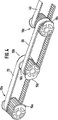
図4は、各場合に共通のベルト20或いは30を駆動している2つのプーリ15a、15b或いは15b、15cによって、ベルト20、30、40に亘るカスケード配列に組み合わされた3つのプーリ10a、10b、10cを有する歯付ベルトプーリシステムを示す。
【0020】
プーリ10aから10cに相当するプーリ10は、図1に斜視図で示され、図2に側面図で示されている。プーリ10は、歯状円周面11、および中心軸孔12の他に、プーリ10に一体に形成されたフランジ部15、16、17を有する。プーリ10は、射出成型により一体の部品としてこの形状に作ることができる。
【0021】
フランジ部15から17は、歯状円周面11を越えて半径方向に立ち上がり、プーリ上で回転するベルトが横方向にずれるのを阻止する。図示されたプーリ10は、ベルト間のスペーサとして機能する中間フランジ部16をともなって、2つのベルトを回転させることを意図している。外側のフランジ部15、17は、作動中に歯状円周面11からベルトが滑り落ちないようにする機能を有する。図1に示すように一つの一体部品の代わりに、同じプーリの複合体を、フランジ部によって互いに分離し、また、各個に横方向にさらなるフランジ部を備えた2つの別体のプーリによって実現することもできる。
【0022】
図2に拡大して示すプーリ10の細部は、歯状円周面11の2つの歯の間の領域を詳細に示す。プーリ10とベルトの作動中に生じる騒音を低減する歯溝4の基部3が設けられている。騒音の低減は、圧縮空気が溝4から逃げることができるようになっていることにより実現される。圧縮空気は、ベルトの歯とプーリ10が噛み合うときに作動中生じる。
【0023】
図1に示す、2つのベルトと、それにより3つのフランジ部15から17を有するプーリ10の場合、フランジ部は、図2に示すように円周の周りに120°離隔している。この理由は、質量を均一に分散して、バランスの異常を好ましく回避すべきだからである。従って、n個のフランジ部を有するプーリにとって、プーリの円周の周りに360°/nのフランジ部の角度間隔は、全く普通のこととなる。角度の間隔は、以下に述べるように、1つの背後に他が位置する、ベルトの一側取付からもたらされる。
【0024】
図3は、カスケード組合せされたプーリシステムの側面図を示す。即ち、2つのベルト20、30或いは30、40が、各回転軸上で回転し、そして、それ故、プーリ10bおよび10cと関連する各回転軸につき、3つのフランジ部15bから17b或いは15cから17cがある。ルート半径は、両プーリ10b、10cについて同じなので、ベルト30の負荷ストランドおよび戻りストランドは互いに平行に延びる。フランジ部15bおよび15cは、ベルト30の負荷ストランドおよび戻りストランド間で案内されることが可能なように、プーリ10の歯元円から出発して延びる。即ち、フランジ部15bおよび15cは、プーリ10b或いは10cのルート円の180°より僅かに少ない範囲に亘って延びている。図3に示された実施例では、ベルト30がフランジ部15bおよび15cのいずれによっても横方向に案内されない領域は、僅かに約2°から3°である。
【0025】
プーリ10bおよび10cの取付ベルト30は、フランジ部15b、15cの特別な形状により非常に簡単である。ベルト30がプーリ10b、10cに横方向に押される前に、プーリ10b、10cは、フランジ部がベルト30の負荷ストランドおよび戻りストランド間に位置するように、それらの外側フランジ部15b、15cが互いに向き合う、図3に示す位置に回転される。次に、フランジ部15b、15cを越えてベルト30を押すことが容易に可能となる。運転中、即ち、プーリ10b、10cが回転しているとき、ベルトは、無視できる程の約2°から3°の小さい範囲以外は、実質的に連続してフランジ部15b、15cによって横方向に案内される。ベルト30が、この短い期間の間、フランジ部15b、15cに乗り上げることを防止するために、フランジ部15b、15cの内側側面は、歯状円周面11(図示せず)の方に傾斜している。これにより、ベルト30が、滑ったとしたら、確実にプーリに押し戻される。
【0026】
このプーリシステムは、通常は、一側からアクセス可能なので、ベルトは、最も後方のベルトから始めて、プーリに1つずつ掛けられる。これについては、図4を参照して以下に説明する。
【0027】
第1に、ベルト20および40は、プーリ10a、10b、10cに掛けられる。ベルト40の場合、図4に示すプーリ10cの位置でなされる。ベルト20もまた、第1に、プーリ10a、10bが図4に示す位置、即ち、外側フランジ部15a、15bが互いに内向きになったプーリ10a、10bにかけられる。次に、プーリ10bは、中間のフランジ部16bが内側を向くように時計回りに120°回転される。同時にプーリ10aは、プーリが組合わされていることにより同様に時計回りに回転し、図4の斜視図では見えない関連する中間のフランジ部16aが同様に内側を向き、フランジ部16bと反対側になる。この状態では、ベルト20は、中間フランジ部16a、16bを越えて、図4に示す後部位置に押されることが可能になる。最後に、ベルト30は、組み合わされていないプーリ10b、10cを、(図4に示す位置を越えて各々180°回転して、図3に示すように)それらの外側フランジ部15b、15cが互いに向き合うように回転することによって取り付けられる。ベルト30は、次に簡単に掛けることができ、これにより縦列配置のプーリシステムが完成する。
【0028】
2つのベルト用の図示のプーリの他に、2つのベルトより1つ以上多く設計されたフランジ部を有するプーリも可能である。プーリに3つ以上のベルトが使用される場合、取り付けるのに、円周方向にフランジ部の寸法を縮小することは役立つかもしれない。
【0029】
取付という点では、最後部のフランジは、ベルトが通常この位置を越えて押されることはないので、完全なフランジ付きのホイールとして設計することができる。
【0030】
発明性のある歯付ベルトプーリシステムは、歯付ベルトが3つ以上のプーリによって案内されるギヤシステムに用いることもできる。円周方向におけるフランジ部の寸法は、次に拡大することができる。
【図面の簡単な説明】
【図1】 一体化されたフランジ部を有する創意工夫に富んだ歯付ベルトプーリの斜視図
【図2】 図1による歯付ベルトプーリの側面図
【図3】 本発明の、縦列配置になった歯付ベルトプーリシステムの側面図
【図4】 本発明の、縦列配置になった歯付ベルトプーリシステムの斜視図[0001]
The present invention relates to a toothed belt pulley having at least one flange and having a toothed circumferential surface engaged with one or more toothed belts. In addition, the present invention relates to a toothed belt pulley system having a plurality of such toothed belt pulleys.
[0002]
The toothed belt pulley system is used in an apparatus for combining a plurality of spaced apart rotating shafts with a toothed belt so that a single motor is sufficient to drive all the combined rotating shafts. The driving of more than two rotating shafts can be ensured by one toothed belt by guiding the belt to a corresponding number of toothed belt pulleys. However, a separate toothed belt can also be provided on the pair of rotating shafts (cascade arrangement).
[0003]
During operation, a flange, in particular for preventing the belt from slipping sideways from the toothed belt pulley, is usually formed by a flanged wheel arranged on one or both sides of the toothed belt pulley.
[0004]
However, the presence of flanged wheels creates problems when installing and replacing toothed belts. The installed belt requires at least a slight preload to ensure reliable engagement with the pulley, even when operating at high loads and high speeds, so that the already assembled toothed belt pulley has a belt It is not easy to place the over the flanged wheel. This problem can be caused by placing a flanged wheel only after placing the belt on the pulley, or by locking the belt only after the pulley has been pivoted to the operating position and the belt is installed, or an excessively long belt. And can only be avoided by preloading it with a separate tension roller after installation. However, these solutions require considerable structural effort.
[0005]
In particular, in a relatively complicated apparatus such as a banknote processing machine in which a large number of rotating shafts are combined in a series through a plurality of toothed belts, structural attempts of the apparatus and maintenance when replacing the belt are performed. The struggle is very big.
[0006]
Accordingly, an object of the present invention is to propose a toothed belt pulley and a toothed belt pulley system that make it possible to easily attach the belt and reliably prevent the belt from slipping off during operation. is there.
[0007]
This problem is solved by the present invention using the toothed belt pulley and the toothed belt pulley system of the independent claims.
[0008]
Preferred embodiments of the invention are described in the dependent claims.
[0009]
In order to solve the problem, it has been proposed that a flange for preventing the belt from slipping off during operation is formed as a flange portion only over a limited part of the circumference of the pulley. When the two rotary shaft of the pulley to be combined to rotate relative to each other, particular the flange portion projecting beyond the circumference of the pulley face each other, the belt, without the flange portion and the abutment, beyond the flange portion 2 It can be attached to one pulley.
[0010]
This is when the belt is attached, the flange portion is located entirely within the interior region of the belt, i.e. to lie between the load strand (load strand) and the return strand (return strand), circumferential pulley It is a premise that the length of the flange portion at is selected. At a predetermined winding angle a of the belt around the pulley, the flange portion can extend in the circumferential direction of the pulley over a clearance angle of 360 ° -a without impinging when the belt is attached. However, local radial height of the flange portion, it should be noted that to adapt to the tangential direction of the belt (tangential course). Similarly large pulley, for example, when combined in conjunction with the drive unit of the roller track (Roller track), the flange should put extend over a slightly smaller range than 180 ° of the circumference of the pulley . However, if have different diameters of the two pulleys to be combined (increased or decreased (multoplication or reduction)), the flange portion of the larger pulley, the flange portion of the smaller pulley (eg 220 °), It extends over a small circumferential angle (eg 140 °).
[0011]
The present invention thus essences that all pulleys can be pre-assembled and that the method can be maintained when the belt or belts are attached or replaced during maintenance. Offer a special advantage.
[0012]
For a relatively complex device driven by one motor and having a large number of rotating shafts arranged in tandem, the two shafts are thus combined simultaneously by separate toothed belts, The rotating shaft is rotated so that the flange portions of the two pulleys are in opposite positions, and the belt is pressed against the pulley through the flange portion . In this way, the belt can be attached successfully in complete tandem.
[0013]
If the belts are in tandem, at least two belts operate in each case on the middle axis of the tandem. In this case, the three flange portions which are shifted in 120 ° position from one another in the circumferential direction, i.e., it is advantageous When one flange portion on each side of one flange portion and the belt between the two belts is formed . When the associated shaft is 120 ° rotated, the belt pressed to the pulley by the above method further pushed rear position beyond the intermediate flange section, i.e. it is possible to enter the rear pulley.
[0014]
Three or more belts can also be run on one axis, accordingly, are evenly distributed circumferentially, must still larger flange portion is provided. When there are n belts, a wheel with n flanges (a wheel with a flange limited to one side) shifted by 360 ° / n or 360 ° / (n + 1) from each other in the circumferential direction, or n + 1 A wheel with a single flange (a wheel with a flange limited to both sides) is preferably formed.
[0015]
The present invention can be similarly applied to a toothed belt pulley system in which one belt is guided by three or more pulleys.
[0016]
According to a preferred embodiment of the present invention, the flange portion is inclined toward the pulley. Thus, during operation, the belt rides on the flange portion and is reliably pushed back to the pulley without slipping or breaking.
[0017]
Inventive flanged toothed belt pulleys can advantageously be implemented as an integral part, for example an injection molded part. Alternatively, the flange portion can be made as a separate part that is attached to the pulley, for example by screwing on its surface, or by sliding it into a shaft adjacent to the pulley.
[0018]
The invention will now be described by way of example with reference to the accompanying drawings, which show further advantages and features of the invention.
[0019]
FIG. 4 shows three
[0020]
A
[0021]
The
[0022]
The detail of the
[0023]
In the case of a
[0024]
FIG. 3 shows a side view of a cascaded pulley system. That is, two
[0025]
The
[0026]
Since this pulley system is usually accessible from one side, the belts are hung one by one on the pulley, starting with the rearmost belt. This will be described below with reference to FIG.
[0027]
First, the
[0028]
The other two of the illustrated pulley for a belt, a pulley is also possible to have one or more number designed flange portion of two belts. If more than two belt pulleys are used, to attach and may help to reduce the size of the flange in the circumferential direction.
[0029]
In terms of mounting, the last flange can be designed as a fully flanged wheel, since the belt is usually not pushed beyond this position.
[0030]
The inventive toothed belt pulley system can also be used in a gear system in which the toothed belt is guided by more than two pulleys. The dimension of the flange portion in the circumferential direction can then be expanded.
[Brief description of the drawings]
FIG. 1 is a perspective view of a creatively toothed belt pulley having an integrated flange portion . FIG. 2 is a side view of the toothed belt pulley according to FIG. 1. FIG. FIG. 4 is a perspective view of the toothed belt pulley system in a tandem arrangement according to the present invention.
Claims (13)
Applications Claiming Priority (3)
| Application Number | Priority Date | Filing Date | Title |
|---|---|---|---|
| DE10019595A DE10019595C2 (en) | 2000-04-20 | 2000-04-20 | Toothed belt wheel with board |
| DE10019595.4 | 2000-04-20 | ||
| PCT/EP2001/004351 WO2001081794A1 (en) | 2000-04-20 | 2001-04-17 | Toothed belt wheel with a collar |
Publications (3)
| Publication Number | Publication Date |
|---|---|
| JP2003532032A JP2003532032A (en) | 2003-10-28 |
| JP2003532032A5 JP2003532032A5 (en) | 2008-01-17 |
| JP4745587B2 true JP4745587B2 (en) | 2011-08-10 |
Family
ID=7639451
Family Applications (1)
| Application Number | Title | Priority Date | Filing Date |
|---|---|---|---|
| JP2001578846A Expired - Fee Related JP4745587B2 (en) | 2000-04-20 | 2001-04-17 | Toothed belt pulley with flange |
Country Status (7)
| Country | Link |
|---|---|
| US (1) | US6932732B2 (en) |
| EP (1) | EP1277002B1 (en) |
| JP (1) | JP4745587B2 (en) |
| AT (1) | ATE251725T1 (en) |
| AU (1) | AU5226401A (en) |
| DE (2) | DE10019595C2 (en) |
| WO (1) | WO2001081794A1 (en) |
Cited By (1)
| Publication number | Priority date | Publication date | Assignee | Title |
|---|---|---|---|---|
| KR20210068771A (en) * | 2019-12-02 | 2021-06-10 | (주)대성하이텍 | Pulley parallel driving system |
Families Citing this family (9)
| Publication number | Priority date | Publication date | Assignee | Title |
|---|---|---|---|---|
| KR100728916B1 (en) * | 2005-11-15 | 2007-06-14 | 권영두 | Timing-belt and combination structure of the same |
| JP2007176120A (en) | 2005-12-28 | 2007-07-12 | Brother Ind Ltd | Carriage driving device and image forming apparatus |
| DE102007010950A1 (en) * | 2007-03-07 | 2008-09-11 | Schaeffler Kg | One-piece drive wheel of a traction mechanism drive |
| US7676951B2 (en) * | 2007-06-26 | 2010-03-16 | General Electric Company | Method and apparatus for linear measurement of a stator core |
| DE202008016466U1 (en) * | 2008-12-15 | 2010-04-22 | Grass Gmbh | Device for the driven movement of an actuator, opening device and furniture |
| US20110118067A1 (en) * | 2009-11-13 | 2011-05-19 | Henry Bronson | Drive with Belt |
| WO2014048123A1 (en) * | 2012-09-29 | 2014-04-03 | Wang Jinfang | V-pulley |
| CN111043264A (en) * | 2019-12-26 | 2020-04-21 | 酒泉市四方装备制造有限公司 | Gear transmission system convenient to adjust and good in service ability |
| CN113175580B (en) * | 2021-06-09 | 2022-06-10 | 成都正升能源技术开发有限公司 | Heating device connected outside oil pipeline |
Citations (4)
| Publication number | Priority date | Publication date | Assignee | Title |
|---|---|---|---|---|
| JPS5820759A (en) * | 1981-07-03 | 1983-02-07 | スミス・アンド・ネフユ−・リサ−チ・リミテツド | Hydraulic cement composition |
| JPS6014340A (en) * | 1983-07-01 | 1985-01-24 | Nippon Telegr & Teleph Corp <Ntt> | Stack control circuit |
| JPS6073961A (en) * | 1983-09-26 | 1985-04-26 | 戸田建設株式会社 | Automatic clamp solidifying concrete |
| JPS6240361A (en) * | 1985-08-13 | 1987-02-21 | Furukawa Electric Co Ltd:The | Production of corrosion resistant copper-base member |
Family Cites Families (14)
| Publication number | Priority date | Publication date | Assignee | Title |
|---|---|---|---|---|
| DE1973434U (en) | 1967-07-13 | 1967-11-30 | Olympia Werke Ag | GEAR WHEEL FOR TIMING BELT DRIVES IN TYPING, BOOKING OR SIMILAR MACHINES. |
| US3650158A (en) * | 1970-05-28 | 1972-03-21 | Us Industries Inc | Feed return wheel for animal feeders |
| US3918515A (en) | 1970-12-28 | 1975-11-11 | Ricoh Kk | Method of making a double flanged timing belt pulley |
| JPS541851B1 (en) * | 1970-12-28 | 1979-01-30 | ||
| US4425007A (en) * | 1981-02-12 | 1984-01-10 | Bucyrus-Erie Company | Tread belt link and cooperating drive tumbler |
| DE3124320A1 (en) * | 1981-06-20 | 1983-01-05 | Dr.Ing.H.C. F. Porsche Ag, 7000 Stuttgart | Toothed belt drive |
| FR2520466A1 (en) | 1982-01-22 | 1983-07-29 | Paumellerie Electrique | Plastics toothed pinion for belt drive - has retaining wings on opposing ends of adjacent grooves to guide belt |
| IT1149696B (en) * | 1982-02-26 | 1986-12-03 | Pirelli | TRANSMISSION WITH TIMING CONGHIA AND TIMING PULLEYS |
| US4805388A (en) * | 1982-05-26 | 1989-02-21 | The Goodyear Tire & Rubber Company | Crop gathering head and belt, sprocket and sheave therefor |
| SE444092B (en) * | 1985-04-29 | 1986-03-17 | Prismavision Ab | DRIVING DEVICE ON SIGNS WITH LOVELY SCREENS |
| US4722722A (en) * | 1986-06-27 | 1988-02-02 | Jepmar Research | Rotatable drive member formed from injection molded plastics material with preform insert |
| JPS6412164A (en) * | 1987-06-30 | 1989-01-17 | Mitsuboshi Belting Ltd | Multi-shaft transmission mechanism with cogged belt |
| US5846470A (en) * | 1994-06-08 | 1998-12-08 | Sumitomo Bakelite Company Limited | Process for production of phenolic resin pulley |
| JPH09177947A (en) * | 1995-12-26 | 1997-07-11 | Shin Kobe Electric Mach Co Ltd | Thermosetting resin-made rotating body and manufacture thereof |
-
2000
- 2000-04-20 DE DE10019595A patent/DE10019595C2/en not_active Expired - Fee Related
-
2001
- 2001-04-17 EP EP01925554A patent/EP1277002B1/en not_active Expired - Lifetime
- 2001-04-17 AT AT01925554T patent/ATE251725T1/en not_active IP Right Cessation
- 2001-04-17 US US10/258,115 patent/US6932732B2/en not_active Expired - Lifetime
- 2001-04-17 AU AU52264/01A patent/AU5226401A/en not_active Abandoned
- 2001-04-17 WO PCT/EP2001/004351 patent/WO2001081794A1/en active IP Right Grant
- 2001-04-17 DE DE50100767T patent/DE50100767D1/en not_active Expired - Lifetime
- 2001-04-17 JP JP2001578846A patent/JP4745587B2/en not_active Expired - Fee Related
Patent Citations (4)
| Publication number | Priority date | Publication date | Assignee | Title |
|---|---|---|---|---|
| JPS5820759A (en) * | 1981-07-03 | 1983-02-07 | スミス・アンド・ネフユ−・リサ−チ・リミテツド | Hydraulic cement composition |
| JPS6014340A (en) * | 1983-07-01 | 1985-01-24 | Nippon Telegr & Teleph Corp <Ntt> | Stack control circuit |
| JPS6073961A (en) * | 1983-09-26 | 1985-04-26 | 戸田建設株式会社 | Automatic clamp solidifying concrete |
| JPS6240361A (en) * | 1985-08-13 | 1987-02-21 | Furukawa Electric Co Ltd:The | Production of corrosion resistant copper-base member |
Cited By (2)
| Publication number | Priority date | Publication date | Assignee | Title |
|---|---|---|---|---|
| KR20210068771A (en) * | 2019-12-02 | 2021-06-10 | (주)대성하이텍 | Pulley parallel driving system |
| KR102298420B1 (en) * | 2019-12-02 | 2021-09-07 | (주)대성하이텍 | Pulley parallel driving system |
Also Published As
| Publication number | Publication date |
|---|---|
| EP1277002B1 (en) | 2003-10-08 |
| ATE251725T1 (en) | 2003-10-15 |
| US6932732B2 (en) | 2005-08-23 |
| JP2003532032A (en) | 2003-10-28 |
| EP1277002A1 (en) | 2003-01-22 |
| DE10019595A1 (en) | 2001-10-31 |
| DE10019595C2 (en) | 2003-02-06 |
| US20030148840A1 (en) | 2003-08-07 |
| AU5226401A (en) | 2001-11-07 |
| DE50100767D1 (en) | 2003-11-13 |
| WO2001081794A1 (en) | 2001-11-01 |
Similar Documents
| Publication | Publication Date | Title |
|---|---|---|
| JP4745587B2 (en) | Toothed belt pulley with flange | |
| JP2023073294A5 (en) | ||
| JPH10184829A (en) | Overrunning clutch pulley device | |
| TWI604137B (en) | Bicycle free wheel hub | |
| CN107636351B (en) | Belt drive mechanism | |
| US5415592A (en) | Auxiliary belt drive mechanism | |
| KR20180127232A (en) | Motor with transmission for bicycle | |
| US6364798B1 (en) | Sprocket for roller chain drives | |
| US3260125A (en) | Gear drive assembly | |
| JP3406518B2 (en) | Roller conveyor | |
| JP2000046133A (en) | Speed change gear | |
| US4936812A (en) | Torque reactive tension mechanism and method | |
| EP1420190A3 (en) | Switchable belt drive | |
| JPS6182061A (en) | V belt transmission device | |
| JPS583143B2 (en) | Kaiten Sadouriyokuden Tatsusouchi | |
| US5316525A (en) | Fulcrum gear assembly | |
| JPH10153241A (en) | Planetary gear-type speed reduction gear | |
| DE10343469A1 (en) | Wrap contact drive especially camshaft chain drive in engine has number of teeth on driving wheel on crankshaft, on intermediate wheels, and on camshaft wheel designed so that drives rotate with differing order and transmission ratio | |
| CN212607674U (en) | Roller transmission connecting structure and conveying line | |
| JPH0754136B2 (en) | Belt type power transmission device | |
| KR19990046818A (en) | reducer | |
| CN211038911U (en) | Variable pitch driving system and wind generating set | |
| WO2010066572A1 (en) | Overrunning clutch for disengageable pulley device | |
| US4299133A (en) | Gearing | |
| KR101895449B1 (en) | Crank assembly for increasing a rotational force |
Legal Events
| Date | Code | Title | Description |
|---|---|---|---|
| A521 | Request for written amendment filed |
Free format text: JAPANESE INTERMEDIATE CODE: A523 Effective date: 20071116 |
|
| A621 | Written request for application examination |
Free format text: JAPANESE INTERMEDIATE CODE: A621 Effective date: 20071116 |
|
| A131 | Notification of reasons for refusal |
Free format text: JAPANESE INTERMEDIATE CODE: A131 Effective date: 20100914 |
|
| A601 | Written request for extension of time |
Free format text: JAPANESE INTERMEDIATE CODE: A601 Effective date: 20101214 |
|
| A602 | Written permission of extension of time |
Free format text: JAPANESE INTERMEDIATE CODE: A602 Effective date: 20101221 |
|
| A521 | Request for written amendment filed |
Free format text: JAPANESE INTERMEDIATE CODE: A523 Effective date: 20110111 |
|
| A01 | Written decision to grant a patent or to grant a registration (utility model) |
Free format text: JAPANESE INTERMEDIATE CODE: A01 Effective date: 20110412 |
|
| A61 | First payment of annual fees (during grant procedure) |
Free format text: JAPANESE INTERMEDIATE CODE: A61 Effective date: 20110512 |
|
| FPAY | Renewal fee payment (event date is renewal date of database) |
Free format text: PAYMENT UNTIL: 20140520 Year of fee payment: 3 |
|
| R150 | Certificate of patent or registration of utility model |
Free format text: JAPANESE INTERMEDIATE CODE: R150 |
|
| R250 | Receipt of annual fees |
Free format text: JAPANESE INTERMEDIATE CODE: R250 |
|
| LAPS | Cancellation because of no payment of annual fees |