JP4745314B2 - Ion pump system and operation method thereof - Google Patents
Ion pump system and operation method thereof Download PDFInfo
- Publication number
- JP4745314B2 JP4745314B2 JP2007287257A JP2007287257A JP4745314B2 JP 4745314 B2 JP4745314 B2 JP 4745314B2 JP 2007287257 A JP2007287257 A JP 2007287257A JP 2007287257 A JP2007287257 A JP 2007287257A JP 4745314 B2 JP4745314 B2 JP 4745314B2
- Authority
- JP
- Japan
- Prior art keywords
- ion pump
- cathode
- anode
- side outlet
- pump system
- Prior art date
- Legal status (The legal status is an assumption and is not a legal conclusion. Google has not performed a legal analysis and makes no representation as to the accuracy of the status listed.)
- Expired - Fee Related
Links
Images


Classifications
-
- Y—GENERAL TAGGING OF NEW TECHNOLOGICAL DEVELOPMENTS; GENERAL TAGGING OF CROSS-SECTIONAL TECHNOLOGIES SPANNING OVER SEVERAL SECTIONS OF THE IPC; TECHNICAL SUBJECTS COVERED BY FORMER USPC CROSS-REFERENCE ART COLLECTIONS [XRACs] AND DIGESTS
- Y02—TECHNOLOGIES OR APPLICATIONS FOR MITIGATION OR ADAPTATION AGAINST CLIMATE CHANGE
- Y02E—REDUCTION OF GREENHOUSE GAS [GHG] EMISSIONS, RELATED TO ENERGY GENERATION, TRANSMISSION OR DISTRIBUTION
- Y02E60/00—Enabling technologies; Technologies with a potential or indirect contribution to GHG emissions mitigation
- Y02E60/30—Hydrogen technology
- Y02E60/50—Fuel cells
Description
本発明は、少なくとも改質装置と、前記改質装置からアノード側に供給される改質ガス中の水素をカソード側に移送させるイオンポンプと、を備えるイオンポンプシステム及びその運転方法に関する。 The present invention relates to an ion pump system including at least a reformer and an ion pump that transfers hydrogen in a reformed gas supplied from the reformer to the anode side to the cathode side, and an operation method thereof.
燃料電池は、燃料ガス(主に水素を含有するガス)及び酸化剤ガス(主に酸素を含有するガス)をアノード側電極及びカソード側電極に供給して電気化学的に反応させることにより、直流の電気エネルギを得るシステムである。 A fuel cell supplies a fuel gas (mainly hydrogen-containing gas) and an oxidant gas (mainly oxygen-containing gas) to the anode-side electrode and the cathode-side electrode and causes them to react electrochemically. It is a system that obtains electrical energy.
例えば、固体高分子型燃料電池は、高分子イオン交換膜からなる電解質膜の両側に、それぞれアノード側電極及びカソード側電極を設けた電解質膜・電極構造体(MEA)を、セパレータによって挟持した発電セルを備えている。この種の発電セルは、通常、電解質膜・電極構造体とセパレータとを所定数だけ積層することにより、燃料電池スタックとして、例えば、自動車等の車両に搭載して使用されている。 For example, in a polymer electrolyte fuel cell, an electrolyte membrane / electrode structure (MEA) provided with an anode electrode and a cathode electrode on both sides of an electrolyte membrane made of a polymer ion exchange membrane is sandwiched by separators. Has a cell. This type of power generation cell is normally used as a fuel cell stack mounted on a vehicle such as an automobile, for example, by laminating a predetermined number of electrolyte membrane / electrode structures and separators.
この場合、上記の燃料電池に供給される燃料ガスとしては、通常、改質装置によって炭化水素系の原燃料から生成される水素ガスが使用されている。改質装置では、一般的に、メタンやLNG等の炭化水素系の原燃料から改質原料ガスを得た後、この改質原料ガスに水蒸気改質や部分酸化改質、又はオートサーマル改質等を施すことにより、改質ガス(燃料ガス)が生成されている。 In this case, as a fuel gas supplied to the fuel cell, a hydrogen gas generated from a hydrocarbon-based raw fuel by a reformer is usually used. In a reformer, generally, a reforming raw material gas is obtained from a hydrocarbon-based raw fuel such as methane or LNG, and then steam reforming, partial oxidation reforming, or autothermal reforming is performed on the reforming raw material gas. As a result, reformed gas (fuel gas) is generated.
改質装置により生成される燃料ガスは、さらに高純度の水素ガス(水素リッチガス)に転換させる必要があるとともに、貯蔵用に圧縮する場合がある。このため、例えば、特許文献1に開示されている燃料電池−イオンポンプ結合体が採用されている。 The fuel gas generated by the reformer needs to be converted to a higher purity hydrogen gas (hydrogen rich gas) and may be compressed for storage. For this reason, for example, a fuel cell-ion pump combination disclosed in Patent Document 1 is employed.
この燃料電池−イオンポンプ結合体は、燃料を受け入れるためのアノード側入口と、燃料を排出するためのアノード側出口と、酸化剤を受け入れるためのカソード側入口と、酸化剤と、精製酸素と精製水素との少なくとも1つとを排出するためのカソード側出口と、第1のコネクタと、第2のコネクタとを備える電気化学セル及び、前記第1及び第2のコネクタに電荷を与え、前記電気化学セルが発電する燃料電池として作用し、前記第1及び第2のコネクタに電位を与え、前記電気化学セルが、水素を精製する水素ポンプと酸素を精製する酸素ポンプとの少なくとも1つとして作用するための制御装置、を備えている。 The fuel cell-ion pump assembly includes an anode inlet for receiving fuel, an anode outlet for discharging fuel, a cathode inlet for receiving an oxidant, an oxidant, purified oxygen, and purified An electrochemical cell comprising a cathode side outlet for discharging at least one of hydrogen, a first connector, and a second connector; and applying an electric charge to the first and second connectors, The cell acts as a fuel cell for generating electricity, applies a potential to the first and second connectors, and the electrochemical cell acts as at least one of a hydrogen pump for purifying hydrogen and an oxygen pump for purifying oxygen. A control device.
ところで、上記の燃料電池−イオンポンプ結合体は、水素製造(水素ポンプ)モードと発電(燃料電池)モードとを有しており、前記水素製造モードでは、アノード側入口に供給された改質ガスから得られる水素は、カソード側出口に昇圧されて送出されている。その際、特に、水素製造モードでの運転中にシステムが緊急停止されると、各種配管に配置されている遮断弁が閉塞されることにより、水素ガスの漏洩を防止している。 The fuel cell-ion pump assembly has a hydrogen production (hydrogen pump) mode and a power generation (fuel cell) mode. In the hydrogen production mode, the reformed gas supplied to the anode side inlet is provided. The hydrogen obtained from the above is boosted to the cathode side outlet and sent out. At that time, in particular, when the system is urgently stopped during the operation in the hydrogen production mode, the shutoff valves arranged in various pipes are closed to prevent hydrogen gas from leaking.
本発明はこの種のシステム緊急停止時における対策に関するものであり、特に水素製造モード時の緊急停止に際し、システムに異常が発生することを可及的に阻止することが可能なイオンポンプシステム及びその運転方法を提供することを目的とする。 The present invention relates to a countermeasure for this kind of system emergency stop, and in particular, an ion pump system capable of preventing the occurrence of an abnormality in the system as much as possible during an emergency stop in the hydrogen production mode, and its The purpose is to provide a driving method.
本発明は、炭化水素を主体とする原燃料を改質して改質ガスを生成する改質装置と、電解質の両側に一対の電極が配設される電解質・電極構造体を有し、前記一対の電極間に電位を印加した状態で、アノード側に前記改質ガスを供給することにより、前記改質ガス中の水素が前記電解質を透過してカソード側に移送されるイオンポンプと、前記イオンポンプの少なくともカソード側出口、アノード側出口及びアノード側入口に連通するそれぞれノーマルクローズ型のカソード側出口流路遮断機構、アノード側出口流路遮断機構及びアノード側入口流路遮断機構と、前記イオンポンプの前記カソード側出口と前記カソード側出口流路遮断機構との間から分岐するカソード側出口分岐流路と、前記カソード側出口分岐流路に配置されるリリーフバルブと、前記カソード側出口分岐流路に、前記リリーフバルブの上流に配置されるノーマルオープン型の電磁弁とを備えている。 The present invention includes a reformer for reforming raw fuel mainly composed of hydrocarbons to generate a reformed gas, and an electrolyte / electrode structure in which a pair of electrodes are disposed on both sides of the electrolyte, An ion pump in which hydrogen in the reformed gas passes through the electrolyte and is transferred to the cathode side by supplying the reformed gas to the anode side with a potential applied between a pair of electrodes; A normally closed cathode side outlet channel blocking mechanism, an anode side outlet channel blocking mechanism and an anode side inlet channel blocking mechanism respectively communicating with at least the cathode side outlet, the anode side outlet and the anode side inlet of the ion pump; A cathode-side outlet branch channel that branches from between the cathode-side outlet of the pump and the cathode-side outlet channel shut-off mechanism, and a relief bar disposed in the cathode-side outlet branch channel And blanking, in the cathode-side outlet branch channel, and a normally-open solenoid valve disposed upstream of the relief valve.
また、イオンポンプは、一対の電極間に電荷を印加した状態で、アノード側に改質ガスを供給するとともに、カソード側に酸化剤ガスを供給することにより発電する発電モードを有することが好ましい。 In addition, the ion pump preferably has a power generation mode in which electric power is generated by supplying a reformed gas to the anode side and an oxidant gas to the cathode side while an electric charge is applied between the pair of electrodes.
さらに、イオンポンプシステムは、イオンポンプのカソード側入口に連通するカソード側入口流路遮断機構と、前記カソード側入口流路遮断機構の上流に配置される酸化剤ガス供給源とを備えることが好ましい。 Further, the ion pump system preferably includes a cathode-side inlet channel blocking mechanism communicating with the cathode-side inlet of the ion pump, and an oxidant gas supply source disposed upstream of the cathode-side inlet channel blocking mechanism. .
さらにまた、酸化剤ガス供給源からイオンポンプに供給される酸化剤ガスの供給圧力は、リリーフバルブが開放される圧力より小さい圧力に設定されることが好ましい。 Furthermore, the supply pressure of the oxidant gas supplied from the oxidant gas supply source to the ion pump is preferably set to a pressure lower than the pressure at which the relief valve is opened.
また、イオンポンプシステムは、イオンポンプから水素が得られる際、電磁弁に通電して前記電磁弁を閉状態に維持する一方、前記イオンポンプで発電される際、前記電磁弁への通電を遮断して該電磁弁を開状態に維持する制御部を備えることが好ましい。 Further, the ion pump system energizes the solenoid valve to keep the solenoid valve closed when hydrogen is obtained from the ion pump, while shuts off the energization to the solenoid valve when power is generated by the ion pump. It is preferable to provide a controller that keeps the electromagnetic valve open.
さらに、イオンポンプのアノード側出口は、アノード側出口流路遮断機構を介装して改質装置を構成する燃焼器に接続されることが好ましい。 Furthermore, it is preferable that the anode side outlet of the ion pump is connected to a combustor constituting the reforming apparatus via an anode side outlet flow path blocking mechanism.
さらにまた、本発明は、炭化水素を主体とする原燃料を改質して改質ガスを生成する改質装置と、電解質の両側に一対の電極が配設される電解質・電極構造体を有し、前記一対の電極間に電位を印加した状態で、アノード側に前記改質ガスを供給することにより、前記改質ガス中の水素が前記電解質を透過してカソード側に移送される水素製造モード、及び前記一対の電極間に電荷を印加した状態で、前記アノード側に前記改質ガスを供給するとともに、前記カソード側に酸化剤ガスを供給することにより発電する発電モードを有するイオンポンプと、前記イオンポンプのカソード側出口、アノード側出口、カソード側入口及びアノード側入口に連通するそれぞれノーマルクローズ型のカソード側出口流路遮断機構、アノード側出口流路遮断機構、カソード側入口流路遮断機構及びアノード側入口流路遮断機構と、前記イオンポンプの前記カソード側出口と前記カソード側出口流路遮断機構との間から分岐するカソード側出口分岐流路と、前記カソード側出口分岐流路に配置されるリリーフバルブと、前記カソード側出口分岐流路に、前記リリーフバルブの上流に配置されるノーマルオープン型の電磁弁とを備えるイオンポンプシステムの運転方法に関するものである。 Furthermore, the present invention includes a reformer that reforms a raw fuel mainly composed of hydrocarbons to generate a reformed gas, and an electrolyte / electrode structure in which a pair of electrodes are disposed on both sides of the electrolyte. Then, by supplying the reformed gas to the anode side with a potential applied between the pair of electrodes, hydrogen in the reformed gas passes through the electrolyte and is transferred to the cathode side. An ion pump having a mode and a power generation mode for generating electricity by supplying the reformed gas to the anode side and supplying an oxidant gas to the cathode side while an electric charge is applied between the pair of electrodes. The cathode side outlet of the ion pump, the anode side outlet, the cathode side inlet, and the anode side inlet respectively communicating with the normally closed cathode side outlet channel blocking mechanism and the anode side outlet channel blocking A cathode-side outlet channel blocking mechanism and an anode-side inlet channel blocking mechanism; a cathode-side outlet branch channel that branches from between the cathode-side outlet and the cathode-side outlet channel blocking mechanism of the ion pump; The present invention relates to a method for operating an ion pump system comprising a relief valve arranged in the cathode side outlet branch flow path, and a normally open type electromagnetic valve arranged in the cathode side outlet branch flow path upstream of the relief valve. It is.
そして、イオンポンプが、水素製造モードで運転される際、電磁弁に通電して前記電磁弁を閉状態に維持する一方、前記イオンポンプが、発電モードで運転される際、前記電磁弁への通電を遮断して該電磁弁を開状態に維持している。 When the ion pump is operated in the hydrogen production mode, the solenoid valve is energized to maintain the solenoid valve in a closed state, while when the ion pump is operated in the power generation mode, The energization is cut off to keep the solenoid valve open.
本発明では、イオンポンプに電位が印加されてカソード側に水素が移送される、所謂、水素製造モード時に、イオンポンプシステムが緊急停止すると、ノーマルクローズ型のカソード側出口流路遮断機構、アノード側出口流路遮断機構及びアノード側入口流路遮断機構が閉塞される一方、ノーマルオープン型の電磁弁が開放される。 In the present invention, when the ion pump system is brought to an emergency stop in a so-called hydrogen production mode in which a potential is applied to the ion pump and hydrogen is transferred to the cathode side, While the outlet channel blocking mechanism and the anode side inlet channel blocking mechanism are closed, the normally open type electromagnetic valve is opened.
その際、カソード側には、アノード側に比べて高圧な水素が保持されている。この比較的高圧な水素は、開放された電磁弁の下流に配置されているリリーフバルブを通って排出されるため、カソード側が所定の圧力まで減圧される。 At that time, hydrogen having a higher pressure than that on the anode side is held on the cathode side. Since this relatively high-pressure hydrogen is discharged through a relief valve disposed downstream of the opened electromagnetic valve, the cathode side is depressurized to a predetermined pressure.
このため、カソード側の水素が、電解質を拡散してアノード側に移動し、このアノード側で前記水素である可燃ガスが昇圧されることを阻止することができる。従って、可燃ガスが、アノード側出口流路遮断機構やアノード側入口流路遮断機構を透過して上流側の設備に影響を与えることを確実に防止することが可能になる。 For this reason, it is possible to prevent the hydrogen on the cathode side from diffusing the electrolyte and moving to the anode side, and the pressure of the combustible gas, which is the hydrogen, on the anode side can be prevented. Therefore, it is possible to reliably prevent the combustible gas from passing through the anode side outlet flow path blocking mechanism or the anode side inlet flow path blocking mechanism and affecting the upstream equipment.
例えば、アノード側出口流路遮断機構の下流側に配設される燃焼器に、可燃ガスが導入されると、前記燃焼器の温度が異常に上昇するおそれがあるからである。これにより、特に水素製造モードでの緊急停止時に、システムに異常が発生することを可及的に阻止することができる。 For example, if combustible gas is introduced into the combustor disposed on the downstream side of the anode side outlet flow path blocking mechanism, the temperature of the combustor may be abnormally increased. As a result, it is possible to prevent as much as possible the occurrence of an abnormality in the system, particularly during an emergency stop in the hydrogen production mode.
また、本発明では、イオンポンプが、発電モードで運転される際、電磁弁への通電を遮断しているため、この電磁弁による電力の消費を良好に抑制することが可能になる。このため、イオンポンプシステム全体の省電力化が容易に図られる。 Further, in the present invention, when the ion pump is operated in the power generation mode, the energization to the solenoid valve is cut off, so that it is possible to favorably suppress the power consumption by the solenoid valve. For this reason, the power saving of the whole ion pump system is achieved easily.
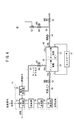
図1は、本発明の第1の実施形態に係るイオンポンプシステム10の概略構成図である。このイオンポンプシステム10は、例えば、家庭用エネルギステーションとして利用される。
FIG. 1 is a schematic configuration diagram of an
イオンポンプシステム10は、炭化水素を主体とする原燃料(例えば、都市ガス)と水蒸気との混合燃料を改質して改質ガスを生成する改質装置12と、後述する発電モード及び水素製造モードを有するFC−イオンポンプ14と、前記FC−イオンポンプ14に接続されるとともに、前記イオンポンプシステム10全体の制御を行うコントローラ(制御部)16とを備える。コントローラ16は、発電モード時にFC−イオンポンプ14に電荷を印加する一方、水素製造モード時に前記FC−イオンポンプ14に電位を印加する機能を有する。
The
改質装置12は、都市ガス中に含まれるメタン(CH4)、エタン(C2H6)、プロパン(C3H6)及びブタン(C4H10)等の炭化水素に水蒸気を混合して混合燃料を得るための熱交換器18と、前記熱交換器18に水蒸気発生用の熱を付与するための触媒燃焼器20と、前記混合燃料を水蒸気改質して改質ガスを得るための改質器22と、シフト反応により前記改質ガス中の一酸化炭素及び水蒸気を二酸化炭素及び水素に変換させるCO変成器(シフト反応器)24と、少量の空気を改質ガスに付加し、選択的に吸収した一酸化炭素と空気中の酸素とを反応させて二酸化炭素に変換させるCO除去器(選択酸化反応器)26とを備える。
The
FC−イオンポンプ14は、固体高分子電解質膜28をアノード側電極30とカソード側電極32とで挟持した電解質膜・電極構造体を備え、前記電解質膜・電極構造体は、図示しないがセパレータと交互に積層されてスタックを構成する。固体高分子電解質膜28としては、例えば、炭化水素系の電解質膜又はパーフルオロカーボン等のフッ素系の電解質膜が使用される。
The FC-
FC−イオンポンプ14は、改質ガスをアノード側電極30に供給するためのアノード側入口34aと、前記アノード側電極30から使用済みの改質ガスを排出するためのアノード側出口34bと、カソード側電極32に酸化剤ガスとして空気を供給するためのカソード側入口36aと、前記カソード側電極32から使用済みの空気を排出するとともに、水素製造モードにより改質ガスから取り出された精製水素ガスを排出するためのカソード側出口36bとを設ける。
The FC-
アノード側入口34aと改質装置12を構成するCO除去器26とは、アノード側入口流路38により接続され、アノード側出口34bと前記改質装置12を構成する触媒燃焼器20とは、アノード側出口流路40により接続される。
The
アノード側入口流路38には、ノーマルクローズ型の電磁弁(遮断機構)42が設けられる。アノード側出口流路40の途上には、ノーマルクローズ型の電磁弁(遮断機構)46が設けられる。
The anode-
カソード側入口36aには、カソード側入口流路48が接続される。このカソード側入口流路48には、ノーマルクローズ型の電磁弁(遮断機構)50と、この電磁弁50の上流に位置してブロア(コンプレッサ)52とが配設される。カソード側出口36bには、カソード側出口流路54が接続される。カソード側出口流路54の下流側には、ノーマルクローズ型の電磁弁(遮断機構)56が設けられる。この電磁弁56の下流には、図示しないが、精製された水素ガスを貯留するための水素貯留ステーションや、この水素ガスを燃料電池車に供給するための水素供給ステーション等が設けられる。
A cathode
カソード側出口流路54には、カソード側出口36bと電磁弁56との間からカソード側出口分岐流路58が分岐する。カソード側出口分岐流路58には、ノーマルオープン型の電磁弁60と、この電磁弁60の下流に位置してリリーフバルブ62とが設けられる。酸化剤ガス供給源であるブロア52からFC−イオンポンプ14に供給される空気の供給圧力は、リリーフバルブ62が開放される圧力より小さい圧力に設定される。
In the cathode
FC−イオンポンプ14では、例えば、アノード側が約10kPa・Gの改質ガス雰囲気であるため、電磁弁42、46としては、小型且つ安価な低圧用の遮断弁が用いられる。一方、カソード側は、例えば、約800kPa・Gに昇圧されており、電磁弁50、56としては、比較的高圧用の遮断弁が用いられる。
In the FC-
このように構成されるイオンポンプシステム10の動作について、以下に説明する。
The operation of the
先ず、改質装置12では、例えば、都市ガス等の原燃料(改質原料)と改質水とが熱交換器18に供給されるとともに、この熱交換器18では、触媒燃焼器20による燃焼熱が付与される。このため、改質水が蒸発して水蒸気が得られ、原燃料と前記水蒸気との混合燃料が改質器22に供給される。
First, in the
改質器22では、水蒸気改質が行われて改質ガスが得られ、この改質ガスは、CO変成器24に供給されることにより、シフト反応が行われる。さらに、改質ガスは、CO除去器26に送られて選択酸化反応が行われた後、アノード側入口流路38に導入される。
In the
ここで、FC−イオンポンプ14が発電モードである際には、コントローラ16を介して、電磁弁60への通電を遮断してこの電磁弁60を開放状態に維持するとともに、アノード側電極30とカソード側電極32とに電荷が印加される。この状態で、改質ガスが、アノード側入口流路38を介してアノード側電極30に供給されるとともに、空気(酸化剤ガス)が、ブロア52の作用下に、カソード側入口流路48を介してカソード側電極32に供給される。従って、FC−イオンポンプ14では、アノード側電極30に供給される改質ガス中の水素と、カソード側電極32に供給される空気中の酸素とを介し、電気化学反応により発電が行われる。
Here, when the FC-
アノード側電極30で使用された改質ガス(未燃の水素ガスを含む)は、アノード側出口34bからアノード側出口流路40を通って触媒燃焼器20に送られ、この触媒燃焼器20に供給される燃焼空気によって燃焼される。一方、カソード側電極32で使用された空気は、カソード側出口36bからカソード側出口流路54を通って外部に排出される。
The reformed gas (including unburned hydrogen gas) used in the anode-
次いで、FC−イオンポンプ14が水素製造モードで運転される際には、図2に示すように、コントローラ16を介して、電磁弁50への通電を遮断してこの電磁弁50を閉状態に維持するとともに、アノード側電極30とカソード側電極32とに電位が印加される。
Next, when the FC-
そして、上記のように、改質装置12からアノード側入口流路38に改質ガスが供給され、この改質ガスは、アノード側入口34aからアノード側電極30に供給される。一方、ブロア52からカソード側電極32に空気の供給が行われていない。
As described above, the reformed gas is supplied from the
ここで、アノード側電極30にプラス極の電位が印加されるとともに、カソード側電極32にマイナス極の電位が印加されている。このため、アノード側電極30では、H2→2H++2e-の反応が起こり、水素イオン(H+)は、固体高分子電解質膜28を透過してカソード側電極32に移動する。このカソード側電極32で、2H++2e-→H2の反応が惹起するとともに、昇圧されている。
Here, a positive electrode potential is applied to the
従って、アノード側電極30からカソード側電極32には、プロトン(水素イオン)が移動し、前記カソード側電極32に高純度の水素ガスが精製される。この水素ガスは、カソード側出口流路54に導入され、図示しない水素貯留ステーション又は水素供給ステーションに送られる。
Accordingly, protons (hydrogen ions) move from the
この場合、本実施形態に係る運転方法では、FC−イオンポンプ14が水素製造モードで運転される際には(図2参照)、ノーマルオープン型の電磁弁60に通電することによりこの電磁弁60が閉状態に維持される一方、前記FC−イオンポンプ14が発電モードで運転される際には(図1参照)、前記電磁弁60への通電が遮断されている。
In this case, in the operation method according to the present embodiment, when the FC-
このため、発電モードにおいて、電磁弁60は、開状態に維持されているが、ブロア52からFC−イオンポンプ14に供給される空気の供給圧力が、リリーフバルブ62が開放される圧力より小さい圧力に設定されている。従って、カソード側出口36bから排出される排ガス(使用済み空気)は、カソード側出口分岐流路58から外部に排出されることがない。
For this reason, in the power generation mode, the
このように、FC−イオンポンプ14が、発電モードで運転される際に、電磁弁60への通電が不要となり、イオンポンプシステム10全体の省電力化を図ることができるという効果が得られる。しかも、リリーフバルブ62を設け、このリリーフバルブ62が開放される圧力と、ブロア52からの空気の供給圧力との関係を設定するだけでよく、コストの高騰を良好に抑制することが可能になる。
As described above, when the FC-
ところで、上記の水素製造モードによる運転時に、イオンポンプシステム10が緊急停止することがある。例えば、コントローラ16が、改質器22の温度及び触媒燃焼器20の温度が異常に上昇したことを検出した際や、図示しないガス漏れセンサにより改質ガスの漏れを検出した際に、イオンポンプシステム10が緊急停止されて電力供給が遮断される。このため、電磁弁42、46、50及び56が閉塞される一方、電磁弁60が開放される。
By the way, the
この場合、FC−イオンポンプ14が水素製造モードで運転されていると、アノード側の改質ガス雰囲気が約10kPa・Gと低圧であるのに対し、カソード側は精製された水素ガスを昇圧するために、約800kPa・Gと高圧になっている。従って、イオンポンプシステム10が緊急停止されることにより、FC−イオンポンプ14のアノード側とカソード側とでは、大きな圧力差が存在し、カソード側の水素が固体高分子電解質膜28を透過してアノード側に移動するおそれがある。
In this case, when the FC-
カソード側からアノード側に水素が拡散されると、アノード側が昇圧されて低圧用遮断弁である電磁弁42、46から漏れた水素ガスが、改質装置12のCO除去器26や触媒燃焼器20に導入される。その際、特に、触媒燃焼器20に過剰な可燃ガスが供給されることにより、前記触媒燃焼器20の温度が異常に上昇するおそれがある。
When hydrogen is diffused from the cathode side to the anode side, the hydrogen gas leaked from the
そこで、第1の実施形態では、カソード側出口流路54から分岐してカソード側出口分岐流路58が設けられるとともに、前記カソード側出口分岐流路58には、ノーマルオープン型の電磁弁60とリリーフバルブ62とが流れ方向に沿って配置されている。このため、イオンポンプシステム10が緊急停止した際には、電磁弁60が開放されるため、昇圧されているカソード側の水素ガスは、カソード側出口分岐流路58を介して排出される(図3参照)。
Therefore, in the first embodiment, a cathode-side
従って、カソード側の比較的高圧な水素ガスは、電磁弁60の下流に配置されているリリーフバルブ62を通って排出され、このリリーフバルブ62の設定圧力に至るまで減圧される。このリリーフバルブ62の設定圧力は、例えば、アノード側の圧力とカソード側の圧力とが略均衡する圧力に設定されることが好ましい。
Accordingly, the relatively high-pressure hydrogen gas on the cathode side is discharged through the
これにより、カソード側の比較的高圧な水素ガスが、固体高分子電解質膜28を拡散してアノード側に移動し、このアノード側で前記水素ガスである可燃ガスが昇圧されることを阻止することができる。このため、可燃ガスが低圧用の電磁弁42、46を透過して上流側の設備である改質装置12に影響を与えることを阻止することが可能になる。
Thereby, the relatively high-pressure hydrogen gas on the cathode side diffuses through the solid
特に、電磁弁46の下流側に配置されている触媒燃焼器20には、必要以上の可燃ガスが導入されることがない。従って、前記触媒燃焼器20の温度が異常に上昇することを阻止し、イオンポンプシステム10に異常が発生することを可及的に防止することができるという効果が得られる。
In particular, the combustible gas more than necessary is not introduced into the
しかも、アノード側の遮断弁である電磁弁42、46は、低圧用の遮断弁を用いることが可能になる。これにより、遮断機構自体が大型化することがなく、しかも、設備費の高騰を抑制することができる。なお、イオンポンプシステム10が通常停止する際には、カソード側出口流路54で圧抜き処理が行われて、アノード側とカソード側とを略同圧に調整した後、前記イオンポンプシステム10全体の電力供給が停止されている。
Moreover, the
図4は、本発明の第2の実施形態に係るイオンポンプシステム70の概略構成図である。なお、第1の実施形態に係るイオンポンプシステム10と同一の構成要素には同一の参照符号を付して、その詳細な説明は省略する。また、以下に説明する第3及び第4の実施形態においても同様に、その詳細な説明は省略する。
FIG. 4 is a schematic configuration diagram of an
イオンポンプシステム70では、アノード側入口流路38にノーマルクローズ型の三方電磁弁72が配置される。三方電磁弁72には、バイパス流路74の一端が接続され、このバイパス流路74の他端は、アノード側出口流路40の途上に電磁弁46の下流に位置して接続される。三方電磁弁72は、非通電時にバイパス流路74側を開にする。
In the
このように構成される第2の実施形態では、特に、改質装置12の運転開始時のように、触媒燃焼温度や改質器22の温度が低く、前記改質装置12から良好な改質ガスが供給される前に、三方電磁弁72を介してこの改質ガスをバイパス流路74から触媒燃焼器20に供給することができる。
In the second embodiment configured as described above, the catalytic combustion temperature and the temperature of the
このため、FC−イオンポンプ14のアノード側電極30に不要なガス成分(特に、CO)が供給されることがなく、前記FC−イオンポンプ14の劣化を防止することができる。
For this reason, unnecessary gas components (particularly, CO) are not supplied to the anode-
なお、改質装置12の運転中の温度安定が確認された後には、三方電磁弁72を切り換えて改質ガスをアノード側電極30に供給し、上記の第1の実施形態と同様の処理が行われる。
After the temperature stability during the operation of the
図5は、本発明の第3の実施形態に係るイオンポンプシステム80の概略構成図である。
FIG. 5 is a schematic configuration diagram of an
このイオンポンプシステム80では、アノード側入口流路38に、電磁弁に代えて逆止弁82が配置される。逆止弁82は、改質装置12から得られる改質ガスをアノード側電極30に向かって供給するものである。この逆止弁82を用いることにより、イオンポンプシステム80全体を一層経済的に構成することができるという効果がある。
In this
図6は、本発明の第4の実施形態に係るイオンポンプシステム90の概略構成図である。
FIG. 6 is a schematic configuration diagram of an
このイオンポンプシステム90は、水素製造モードのみを有するイオンポンプ92を備えている。イオンポンプ92は、前述したFC−イオンポンプ14における水素製造モード時の同様の運転処理が行われる。
The
従って、第4の実施形態では、イオンポンプ92による水素製造運転時に、イオンポンプシステム90が緊急停止して電力供給が遮断された際、カソード側の高圧な水素ガスは、電磁弁60及びリリーフバルブ62を介して確実に放出される。このため、前記カソード側からアノード側に水素が拡散することを良好に阻止することが可能になる。
Therefore, in the fourth embodiment, when the
これにより、第4の実施形態では、上記の第1〜第3の実施形態と同様の効果が得られる。 Thereby, in 4th Embodiment, the effect similar to said 1st-3rd embodiment is acquired.
10、70、80、90…イオンポンプシステム
12…改質装置 14…FC−イオンポンプ
16…コントローラ 18…熱交換器
20…触媒燃焼器 22…改質器
24…CO変成器 26…CO除去器
28…固体高分子電解質膜 30…アノード側電極
32…カソード側電極 34a…アノード側入口
34b…アノード側出口 36a…カソード側入口
36b…カソード側出口 38…アノード側入口流路
40…アノード側出口流路 42、46、50、56、60…電磁弁
48…カソード側入口流路 54…カソード側出口流路
58…カソード側出口分岐流路 62…リリーフバルブ
72…三方電磁弁 74…バイパス流路
82…逆止弁 92…イオンポンプ
DESCRIPTION OF
Claims (7)
電解質の両側に一対の電極が配設される電解質・電極構造体を有し、前記一対の電極間に電位を印加した状態で、アノード側に前記改質ガスを供給することにより、前記改質ガス中の水素が前記電解質を透過してカソード側に移送されるイオンポンプと、
前記イオンポンプの少なくともカソード側出口、アノード側出口及びアノード側入口に連通するそれぞれノーマルクローズ型のカソード側出口流路遮断機構、アノード側出口流路遮断機構及びアノード側入口流路遮断機構と、
前記イオンポンプの前記カソード側出口と前記カソード側出口流路遮断機構との間から分岐するカソード側出口分岐流路と、
前記カソード側出口分岐流路に配置されるリリーフバルブと、
前記カソード側出口分岐流路に、前記リリーフバルブの上流に配置されるノーマルオープン型の電磁弁と、
を備えることを特徴とするイオンポンプシステム。 A reformer that reforms raw fuel mainly composed of hydrocarbons to generate reformed gas;
The reforming is performed by supplying the reformed gas to the anode side with an electrolyte / electrode structure in which a pair of electrodes are disposed on both sides of the electrolyte, and a potential is applied between the pair of electrodes. An ion pump in which hydrogen in the gas passes through the electrolyte and is transferred to the cathode side;
A normally closed cathode-side outlet channel blocking mechanism, an anode-side outlet channel blocking mechanism, and an anode-side inlet channel blocking mechanism respectively communicating with at least the cathode-side outlet, the anode-side outlet, and the anode-side inlet of the ion pump;
A cathode-side outlet branch channel that branches from between the cathode-side outlet of the ion pump and the cathode-side outlet channel blocking mechanism;
A relief valve disposed in the cathode side outlet branch flow path;
A normally open solenoid valve disposed upstream of the relief valve in the cathode-side outlet branch flow path;
An ion pump system comprising:
前記カソード側入口流路遮断機構の上流に配置される酸化剤ガス供給源と、
を備えることを特徴とするイオンポンプシステム。 The ion pump system according to claim 2, wherein a cathode side inlet flow path blocking mechanism communicating with a cathode side inlet of the ion pump;
An oxidant gas supply source disposed upstream of the cathode-side inlet channel blocking mechanism;
An ion pump system comprising:
電解質の両側に一対の電極が配設される電解質・電極構造体を有し、前記一対の電極間に電位を印加した状態で、アノード側に前記改質ガスを供給することにより、前記改質ガス中の水素が前記電解質を透過してカソード側に移送される水素製造モード、及び前記一対の電極間に電荷を印加した状態で、前記アノード側に前記改質ガスを供給するとともに、前記カソード側に酸化剤ガスを供給することにより発電する発電モードを有するイオンポンプと、
前記イオンポンプのカソード側出口、アノード側出口、カソード側入口及びアノード側入口に連通するそれぞれノーマルクローズ型のカソード側出口流路遮断機構、アノード側出口流路遮断機構、カソード側入口流路遮断機構及びアノード側入口流路遮断機構と、
前記イオンポンプの前記カソード側出口と前記カソード側出口流路遮断機構との間から分岐するカソード側出口分岐流路と、
前記カソード側出口分岐流路に配置されるリリーフバルブと、
前記カソード側出口分岐流路に、前記リリーフバルブの上流に配置されるノーマルオープン型の電磁弁と、
を備えるイオンポンプシステムの運転方法であって、
前記イオンポンプが、前記水素製造モードで運転される際、前記電磁弁に通電して該電磁弁を閉状態に維持する一方、
前記イオンポンプが、前記発電モードで運転される際、前記電磁弁への通電を遮断して該電磁弁を開状態に維持することを特徴とするイオンポンプシステムの運転方法。 A reformer for reforming raw fuel mainly composed of hydrocarbons to generate reformed gas;
The reforming is performed by supplying the reformed gas to the anode side with an electrolyte / electrode structure in which a pair of electrodes are disposed on both sides of the electrolyte, and a potential is applied between the pair of electrodes. In the hydrogen production mode in which hydrogen in the gas passes through the electrolyte and is transferred to the cathode side, and the charge is applied between the pair of electrodes, the reformed gas is supplied to the anode side, and the cathode An ion pump having a power generation mode for generating power by supplying an oxidant gas to the side;
Normally closed type cathode side outlet channel blocking mechanism, anode side outlet channel blocking mechanism, cathode side inlet channel blocking mechanism communicating with the cathode side outlet, anode side outlet, cathode side inlet and anode side inlet of the ion pump, respectively. And an anode side inlet channel blocking mechanism;
A cathode-side outlet branch channel that branches from between the cathode-side outlet of the ion pump and the cathode-side outlet channel blocking mechanism;
A relief valve disposed in the cathode side outlet branch flow path;
A normally open solenoid valve disposed upstream of the relief valve in the cathode-side outlet branch flow path;
An ion pump system operating method comprising:
When the ion pump is operated in the hydrogen production mode, the solenoid valve is energized to keep the solenoid valve closed,
An operation method of an ion pump system, wherein when the ion pump is operated in the power generation mode, the energization to the electromagnetic valve is cut off and the electromagnetic valve is maintained in an open state.
Priority Applications (1)
| Application Number | Priority Date | Filing Date | Title |
|---|---|---|---|
| JP2007287257A JP4745314B2 (en) | 2007-11-05 | 2007-11-05 | Ion pump system and operation method thereof |
Applications Claiming Priority (1)
| Application Number | Priority Date | Filing Date | Title |
|---|---|---|---|
| JP2007287257A JP4745314B2 (en) | 2007-11-05 | 2007-11-05 | Ion pump system and operation method thereof |
Publications (2)
| Publication Number | Publication Date |
|---|---|
| JP2009114012A JP2009114012A (en) | 2009-05-28 |
| JP4745314B2 true JP4745314B2 (en) | 2011-08-10 |
Family
ID=40781584
Family Applications (1)
| Application Number | Title | Priority Date | Filing Date |
|---|---|---|---|
| JP2007287257A Expired - Fee Related JP4745314B2 (en) | 2007-11-05 | 2007-11-05 | Ion pump system and operation method thereof |
Country Status (1)
| Country | Link |
|---|---|
| JP (1) | JP4745314B2 (en) |
Families Citing this family (7)
| Publication number | Priority date | Publication date | Assignee | Title |
|---|---|---|---|---|
| TWI384679B (en) * | 2009-12-14 | 2013-02-01 | Ind Tech Res Inst | Power supply device |
| CN102117926B (en) * | 2009-12-30 | 2014-11-26 | 财团法人工业技术研究院 | Power supply device |
| JP6299027B2 (en) * | 2013-12-16 | 2018-03-28 | 国立大学法人山梨大学 | Hydrogen refining pressurization system and operation method thereof |
| JP6979626B2 (en) * | 2017-08-04 | 2021-12-15 | パナソニックIpマネジメント株式会社 | Hydrogen supply system |
| JP7065276B2 (en) * | 2018-12-26 | 2022-05-12 | パナソニックIpマネジメント株式会社 | Hydrogen generation system and its operation method |
| WO2022118490A1 (en) * | 2020-12-03 | 2022-06-09 | パナソニックIpマネジメント株式会社 | Hydrogen system and method for operating hydrogen system |
| JP7008202B1 (en) * | 2020-12-03 | 2022-01-25 | パナソニックIpマネジメント株式会社 | Hydrogen system and how to operate the hydrogen system |
Family Cites Families (6)
| Publication number | Priority date | Publication date | Assignee | Title |
|---|---|---|---|---|
| JPS6096501A (en) * | 1983-07-29 | 1985-05-30 | Nippon Kucho Eng Kk | Multi-purpose metal hydride utilization system |
| JPH08180895A (en) * | 1994-12-26 | 1996-07-12 | Aisin Aw Co Ltd | Fuel cell generating device |
| JP2003208912A (en) * | 2002-01-11 | 2003-07-25 | Aisin Seiki Co Ltd | Fuel cell power generation system |
| US6835479B2 (en) * | 2002-06-26 | 2004-12-28 | Utc Fuel Cells, Llc | System and method for shutting down a fuel cell power plant |
| US7252900B2 (en) * | 2003-09-09 | 2007-08-07 | Plug Power Inc. | Combination fuel cell and ion pump, and methods and infrastructure systems employing same |
| JP4648650B2 (en) * | 2004-01-26 | 2011-03-09 | 株式会社豊田中央研究所 | Fuel cell system |
-
2007
- 2007-11-05 JP JP2007287257A patent/JP4745314B2/en not_active Expired - Fee Related
Also Published As
| Publication number | Publication date |
|---|---|
| JP2009114012A (en) | 2009-05-28 |
Similar Documents
| Publication | Publication Date | Title |
|---|---|---|
| JP4745314B2 (en) | Ion pump system and operation method thereof | |
| JP5011673B2 (en) | Fuel cell power generation system | |
| US6395414B1 (en) | Staged venting of fuel cell system during rapid shutdown | |
| KR20210029213A (en) | Fuel cell system and control method thereof | |
| WO2019160036A1 (en) | Fuel cell system, hybrid power generation system, and control method for fuel cell system | |
| US20070065692A1 (en) | Purge system for fuel cell | |
| US8158287B2 (en) | Fuel cell | |
| JP5081574B2 (en) | Operation method when load of fuel cell system increases | |
| JP4463846B2 (en) | Hydrogen production power generation system | |
| JP2013258004A (en) | High-temperature fuel cell system | |
| KR101245766B1 (en) | System and method for operating fuel cell of emergency state | |
| US8053118B2 (en) | Hydrogen and power generation system and method for shutting down the same | |
| JP2009059668A (en) | Fuel cell system, and operation method thereof | |
| US20070154745A1 (en) | Purging a fuel cell system | |
| JP2011100610A (en) | Hydrogen processing system | |
| JP4727642B2 (en) | Operation method of hydrogen production power generation system | |
| JP2009104885A (en) | Operation method on load decrease of fuel cell system | |
| JP5002220B2 (en) | Fuel cell system | |
| JP5064785B2 (en) | Fuel cell system | |
| WO2005020359A1 (en) | Fuel cell system and method for stopping operation of fuel cell system | |
| JP2009283278A (en) | Fuel cell system | |
| JP2009117170A (en) | Hydrogen and power generating system, and load following power generation method therein | |
| JP4741568B2 (en) | Hydrogen production method for hydrogen production power generation system | |
| JP2008146851A (en) | Shutdown method of fuel cell power generating device and fuel cell power generating device | |
| JP2007035359A (en) | Fuel cell system |
Legal Events
| Date | Code | Title | Description |
|---|---|---|---|
| A977 | Report on retrieval |
Free format text: JAPANESE INTERMEDIATE CODE: A971007 Effective date: 20110407 |
|
| A01 | Written decision to grant a patent or to grant a registration (utility model) |
Free format text: JAPANESE INTERMEDIATE CODE: A01 Effective date: 20110412 |
|
| A61 | First payment of annual fees (during grant procedure) |
Free format text: JAPANESE INTERMEDIATE CODE: A61 Effective date: 20110511 |
|
| FPAY | Renewal fee payment (event date is renewal date of database) |
Free format text: PAYMENT UNTIL: 20140520 Year of fee payment: 3 |
|
| R150 | Certificate of patent or registration of utility model |
Free format text: JAPANESE INTERMEDIATE CODE: R150 |
|
| LAPS | Cancellation because of no payment of annual fees |