JP4744827B2 - Pressure sensor device, ventricular catheter, and method for manufacturing an intraventricular pressure sensor device - Google Patents
Pressure sensor device, ventricular catheter, and method for manufacturing an intraventricular pressure sensor device Download PDFInfo
- Publication number
- JP4744827B2 JP4744827B2 JP2004241288A JP2004241288A JP4744827B2 JP 4744827 B2 JP4744827 B2 JP 4744827B2 JP 2004241288 A JP2004241288 A JP 2004241288A JP 2004241288 A JP2004241288 A JP 2004241288A JP 4744827 B2 JP4744827 B2 JP 4744827B2
- Authority
- JP
- Japan
- Prior art keywords
- lumen
- catheter
- pressure sensor
- pressure
- fluid
- Prior art date
- Legal status (The legal status is an assumption and is not a legal conclusion. Google has not performed a legal analysis and makes no representation as to the accuracy of the status listed.)
- Expired - Fee Related
Links
Images


Classifications
-
- A—HUMAN NECESSITIES
- A61—MEDICAL OR VETERINARY SCIENCE; HYGIENE
- A61B—DIAGNOSIS; SURGERY; IDENTIFICATION
- A61B5/00—Measuring for diagnostic purposes; Identification of persons
- A61B5/03—Detecting, measuring or recording fluid pressure within the body other than blood pressure, e.g. cerebral pressure; Measuring pressure in body tissues or organs
- A61B5/031—Intracranial pressure
-
- A—HUMAN NECESSITIES
- A61—MEDICAL OR VETERINARY SCIENCE; HYGIENE
- A61M—DEVICES FOR INTRODUCING MEDIA INTO, OR ONTO, THE BODY; DEVICES FOR TRANSDUCING BODY MEDIA OR FOR TAKING MEDIA FROM THE BODY; DEVICES FOR PRODUCING OR ENDING SLEEP OR STUPOR
- A61M25/00—Catheters; Hollow probes
- A61M2025/0001—Catheters; Hollow probes for pressure measurement
- A61M2025/0003—Catheters; Hollow probes for pressure measurement having an additional lumen transmitting fluid pressure to the outside for measurement
-
- A—HUMAN NECESSITIES
- A61—MEDICAL OR VETERINARY SCIENCE; HYGIENE
- A61M—DEVICES FOR INTRODUCING MEDIA INTO, OR ONTO, THE BODY; DEVICES FOR TRANSDUCING BODY MEDIA OR FOR TAKING MEDIA FROM THE BODY; DEVICES FOR PRODUCING OR ENDING SLEEP OR STUPOR
- A61M27/00—Drainage appliance for wounds or the like, i.e. wound drains, implanted drains
- A61M27/002—Implant devices for drainage of body fluids from one part of the body to another
- A61M27/006—Cerebrospinal drainage; Accessories therefor, e.g. valves
Landscapes
- Health & Medical Sciences (AREA)
- Life Sciences & Earth Sciences (AREA)
- Medical Informatics (AREA)
- Molecular Biology (AREA)
- Hematology (AREA)
- Biophysics (AREA)
- Pathology (AREA)
- Engineering & Computer Science (AREA)
- Biomedical Technology (AREA)
- Heart & Thoracic Surgery (AREA)
- Neurosurgery (AREA)
- Physics & Mathematics (AREA)
- Surgery (AREA)
- Animal Behavior & Ethology (AREA)
- General Health & Medical Sciences (AREA)
- Public Health (AREA)
- Veterinary Medicine (AREA)
- Measuring And Recording Apparatus For Diagnosis (AREA)
- External Artificial Organs (AREA)
- Measuring Pulse, Heart Rate, Blood Pressure Or Blood Flow (AREA)
- Media Introduction/Drainage Providing Device (AREA)
Description
本発明は、圧力センサを備えたカテーテル装置に関する。 The present invention relates to a catheter device provided with a pressure sensor.
水頭症は、脳の脳室または脳室腔内での脳脊髄液(CSF)の異常な蓄積よって引き起こされる神経症状である。CSFは、主に脈絡叢で生成される無色透明の液体であり、脳及び脊髄を覆っている。CSFは、脳の脳室系を絶えず循環し、最終的には血流内に吸収される。CSFは、脳及び脊髄の保護に役立っている。CSFが脳及び脊髄を浮揚させ、中枢神経の損傷を防ぐ保護クッションすなわち「ショックアブソーバー」としての役割を果たしている。 Hydrocephalus is a neurological symptom caused by abnormal accumulation of cerebrospinal fluid (CSF) in the cerebral ventricles or chambers. CSF is a colorless and transparent liquid produced mainly in the choroid plexus and covers the brain and spinal cord. CSF constantly circulates through the ventricular system of the brain and is eventually absorbed into the bloodstream. CSF helps protect the brain and spinal cord. The CSF acts as a protective cushion or “shock absorber” that floats the brain and spinal cord and prevents damage to the central nervous system.
子供にも大人にも起こる水頭症は、何らかの理由により脳におけるCSFの正常な排出が阻害された時に起こる。このような阻害は、例えば、遺伝的素因、脳室内出血、頭蓋内出血、髄膜などの感染症、または頭部外傷などを含む様々な因子によって引き起こされる。CSFの流れが遮断されると、脈絡叢で生成されるCSFの量とCSFが血流内に吸収される速度とのバランスが崩れ、脳内の圧力が上昇して脳室が膨張する。 Hydrocephalus, which occurs in both children and adults, occurs when the normal excretion of CSF in the brain is inhibited for some reason. Such inhibition is caused by a variety of factors including, for example, genetic predisposition, intraventricular hemorrhage, intracranial hemorrhage, infections such as meninges, or head trauma. When the flow of CSF is interrupted, the balance between the amount of CSF generated in the choroid plexus and the rate at which CSF is absorbed into the bloodstream is lost, the pressure in the brain rises, and the ventricle expands.
水頭症は、CSFの流れを脳室から体内の他の領域に迂回させ、そこでCSFが循環系の一部として吸収されるようにするシャントシステムを外科的に挿入して治療される場合が多い。シャントシステムには様々なモデルがあるが、通常は同様の機能的な構成要素が用いられている。このような構成要素には、骨孔を介して患者の頭蓋内に挿入され脳室に移植される脳室カテーテル、CSFを最終的な排出部位に移送する排出カテーテル、並びにシャント弁などのオプションの流量調節機構が含まれる。このようなシャント弁は、CSFを脳室から排出部位への一方向の流れを調節して脳室の圧力を正常に保つ。脳室カテーテルは通常、シャントシステム内にCSFが流入できるように、その長さに沿って配置された複数の孔すなわち開口を有する。脳室カテーテルの内腔内に設けられた取り外し可能な硬質のスタイレットを用いて、カテーテルを所望の標的部位に導いて、カテーテルの挿入を容易にする。これに加えて或いは別法では、先の尖っていない脳カニューレ及び引き剥がせるシースを用いてカテーテルの配置を容易にする。 Hydrocephalus is often treated by surgically inserting a shunt system that diverts the flow of CSF from the ventricle to other areas of the body where it is absorbed as part of the circulatory system. . There are various models of shunt systems, but usually the same functional components are used. Such components include optional ventricular catheters that are inserted into the patient's skull through the bone hole and implanted into the ventricle, drainage catheters that transport the CSF to the final drainage site, and optional shunt valves. A flow control mechanism is included. Such a shunt valve keeps the ventricular pressure normal by regulating the unidirectional flow of CSF from the ventricle to the discharge site. Ventricular catheters typically have a plurality of holes or openings arranged along their length so that CSF can flow into the shunt system. A removable rigid stylet provided within the lumen of the ventricular catheter is used to guide the catheter to the desired target site to facilitate catheter insertion. In addition or alternatively, a non-pointed brain cannula and a peelable sheath may be used to facilitate catheter placement.
脳室カテーテルの使用に関連した一般的な問題は、患者の脳室内の圧力測定が困難なことである。現在、脳室内の圧力測定には2つの技術を用いることができる。一方の技術では、脳室内にテレメトリにより通信できる小型圧力センサを配置する。しかしながら、このような圧力センサは、高度に小型化する必要があるため、環境の悪化による影響を受け易い。他方の技術では、脳脊髄液に連通した圧力センサを脳室の遠位側に直列に配置する。カテーテルにおける圧力低下はごく僅かであるため、センサが脳室内の圧力に近い圧力を測定できる。この技術は、比較的大きなセンサを使用できるという利点があるが、カテーテルが閉塞するとセンサによる圧力検出が妨げられ、脳室内の圧力を正確に測定することができない。 A common problem associated with the use of ventricular catheters is the difficulty in measuring pressure in the patient's ventricle. Currently, two techniques can be used to measure pressure in the ventricle. In one technique, a small pressure sensor that can communicate by telemetry is placed in the ventricle. However, since such a pressure sensor needs to be highly miniaturized, it is easily affected by environmental deterioration. In the other technique, a pressure sensor communicating with the cerebrospinal fluid is placed in series on the distal side of the ventricle. Since the pressure drop in the catheter is negligible, the sensor can measure a pressure close to the pressure in the ventricle. This technique has the advantage that a relatively large sensor can be used, but if the catheter is occluded, pressure detection by the sensor is hindered, and the pressure in the ventricle cannot be measured accurately.
従って、患者の脳室圧力を正確に測定できる圧力センサを備えたカテーテルが要望されている。 Accordingly, there is a need for a catheter with a pressure sensor that can accurately measure a patient's ventricular pressure.
本発明は、内部を流れる流体を受容するように適合された第1の内腔と別の流体が封入され、流体不浸透性の密閉された別の第2の内腔とを有する細長いカテーテルを備えた圧力センサ装置を提供する。第2の内腔は、外部圧力源にさらされるように適合された感圧要素とその感圧要素の変位に応答して外部圧力源の圧力を測定できる圧力センサとの間に延在する。第1の内腔は、少なくとも1つの流体入口ポートを含むことができる。流体入口ポートは、内部に流体を受容するために基端側の圧力センサの先端側に位置するカテーテルの壁部を貫いて形成されている。 The present invention provides an elongate catheter having a first lumen adapted to receive fluid flowing therein and another sealed fluid-impermeable second lumen. A pressure sensor device is provided. The second lumen extends between a pressure sensitive element adapted to be exposed to an external pressure source and a pressure sensor capable of measuring the pressure of the external pressure source in response to displacement of the pressure sensitive element. The first lumen can include at least one fluid inlet port. The fluid inlet port is formed through the wall of the catheter located on the distal side of the proximal pressure sensor for receiving fluid therein.
一実施形態では、感圧要素は、第2の内腔の先端部に配設され、圧力センサは第2の内腔の基端部に取り付けられている。感圧要素は、第2の内腔内の流体に接触した第1の表面と、外部圧力源にさらされるように適合された反対側の第2の表面とを含む。例示的な実施形態では、感圧要素は、好ましくはカテーテルの側壁に形成された開口にわたって配設される可撓性の膜である。この可撓性の膜は、約0.05μL/mmHg〜2μL/mmHgの範囲のコンプライアンスを有することができる。 In one embodiment, the pressure sensitive element is disposed at the distal end of the second lumen and the pressure sensor is attached to the proximal end of the second lumen. The pressure sensitive element includes a first surface in contact with the fluid in the second lumen and an opposing second surface adapted to be exposed to an external pressure source. In an exemplary embodiment, the pressure sensitive element is a flexible membrane that is preferably disposed over an opening formed in the side wall of the catheter. The flexible membrane can have a compliance in the range of about 0.05 μL / mmHg to 2 μL / mmHg.
本発明の更に別の実施形態では、内部を流れる流体を受容するように適合された第1の内腔と、カテーテルの先端部に配設された可撓性の膜に接続された圧力センサを有する流体が封入された第2の内腔とを有する細長い部材を備えた脳室カテーテルを提供する。この可撓性の膜が、カテーテルが患者の脳室内に移植された時に脳室内の圧力の変化に応答するように適合されているため、脳室内の圧力を直接測定することができる。圧力センサは、流体が封入された第2の内腔の基端部に取り付けることができる。例示的な実施形態では、可撓性の膜は、実質組織の圧力の変化に応答できるようにカテーテルの中間部分に配設することができる。 In yet another embodiment of the invention, a pressure sensor connected to a first lumen adapted to receive fluid flowing therein and a flexible membrane disposed at the distal end of the catheter. A ventricular catheter is provided having an elongate member having a second lumen enclosing a fluid having the fluid. Because this flexible membrane is adapted to respond to changes in pressure in the ventricle when the catheter is implanted in the patient's ventricle, the pressure in the ventricle can be measured directly. The pressure sensor can be attached to the proximal end of the second lumen enclosing the fluid. In an exemplary embodiment, a flexible membrane can be disposed in the middle portion of the catheter so that it can respond to changes in parenchymal pressure.
本発明はまた、脳室カテーテルを用いて脳室内の圧力を測定する方法を提供する。このカテーテルは、内部を流れる流体を受容するように適合された第1の内腔と、流体が封入され流体不浸透性の第2の内腔とを有する。第2の内腔は、患者の脳室の圧力の変化に応答するように適合された先端側の感圧部材と圧力の変化を測定するように適合された基端側の圧力センサとの間に延在する。この方法は、感圧部材が脳室内に配設され、圧力センサが脳室の外部に配設されるように患者の脳室内に脳室カテーテルを移植するステップと、患者の脳室内の少なくとも1つの圧力の値を得るステップとを含む。 The present invention also provides a method for measuring the pressure in the ventricle using a ventricular catheter. The catheter has a first lumen adapted to receive fluid flowing therethrough and a second lumen that is encapsulated and impermeable to fluid. The second lumen is between a distal pressure sensitive member adapted to respond to pressure changes in the patient's ventricle and a proximal pressure sensor adapted to measure pressure changes. Extend to. The method includes the steps of implanting a ventricular catheter in the patient's ventricle such that the pressure sensitive member is disposed in the ventricle and the pressure sensor is disposed outside the ventricle, and at least one in the patient's ventricle. Obtaining two pressure values.
本発明の他の態様では、脳室内圧力センサ装置を製造するための方法を提供する。この方法は、内部を流れる流体を受容するように適合された第1の内腔、及び基端側圧力センサとカテーテルの側壁に形成された開口に連通した先端部との間に延在する第2の内腔を有するカテーテルを形成するステップを含む。次に、第2の内腔を流体で満たし、溶剤系溶液をカテーテルの側壁に形成された開口にわたってスプレーし、カテーテルの第2の内腔内に流体を密閉する可撓性の膜を形成する。この溶剤系溶液は、カテーテルに接着できなければならない。第2の内腔が流体で満たされ、カテーテルに溶液をスプレーする前に、第2の内腔内の全ての空隙が取り除かれるのが好ましい。 In another aspect of the invention, a method for manufacturing an intraventricular pressure sensor device is provided. The method includes a first lumen adapted to receive a fluid flowing therein, and a first portion extending between a proximal pressure sensor and a distal end in communication with an opening formed in the side wall of the catheter. Forming a catheter having two lumens. Next, the second lumen is filled with fluid and a solvent-based solution is sprayed over the opening formed in the side wall of the catheter to form a flexible membrane that seals the fluid within the second lumen of the catheter. . This solvent-based solution must be able to adhere to the catheter. Preferably, the second lumen is filled with fluid and all voids in the second lumen are removed before the solution is sprayed onto the catheter.
患者の脳室圧力を正確に測定できる圧力センサを備えたカテーテルが提供される。 A catheter with a pressure sensor that can accurately measure a patient's ventricular pressure is provided.
本発明は、添付の図面を参照しながら以下の詳細な説明を読むとより良く理解できるであろう。 The invention will be better understood upon reading the following detailed description with reference to the accompanying drawings.
本発明は、カテーテルを備えた脳室内圧力センサ装置を提供する。このカテーテルは、内部を流れる流体を受容する第1の内腔と、流体が封入された流体不浸透性の別の第2の内腔とを有する。第2の内腔は、外部圧力源にさらされるように適合された感圧要素と、感圧要素の変位に応答して外部圧力源の圧力を測定することができる圧力センサとの間に延在する。第2の内腔内に満たされている流体は、非圧縮性流体である。これにより、感圧要素材よって検出された圧力が圧力センサに直接伝達されるため、対象の圧力に直接は連通していない検出素子で圧力を測定することが可能となる。脳室内圧力センサ装置は、特に患者の脳室圧力を直接測定できるという利点がある。 The present invention provides an intraventricular pressure sensor device including a catheter. The catheter has a first lumen for receiving fluid flowing therein and another fluid-impermeable second lumen in which the fluid is enclosed. The second lumen extends between a pressure sensitive element adapted to be exposed to an external pressure source and a pressure sensor capable of measuring the pressure of the external pressure source in response to displacement of the pressure sensitive element. Exists. The fluid filled in the second lumen is an incompressible fluid. As a result, the pressure detected by the pressure-sensitive element material is directly transmitted to the pressure sensor, so that the pressure can be measured by a detection element that is not in direct communication with the target pressure. The intraventricular pressure sensor device is particularly advantageous in that it can directly measure the patient's ventricular pressure.
本装置は、患者の脳室の圧力を測定するために用いられる脳室カテーテルとして記載したが、当業者であれば、本装置を様々な腔内の圧力を測定する種々の医療処置に用いることができることを理解できよう。限定するものではないが、例えば、本装置を改変して実質組織内の圧力を測定することができる。 Although this device has been described as a ventricular catheter used to measure the pressure in a patient's ventricle, those skilled in the art can use this device for various medical procedures that measure the pressure in various cavities. You can understand that you can. For example, without limitation, the device can be modified to measure the pressure in the parenchyma.
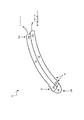
図1及び図2に、細長いカテーテル10を備えた脳室内圧力センサ装置の例示的な実施形態が例示されている。このカテーテル10は、基端部10a、先端部10b、及び内腔12などの少なくとも1つの内腔を有する。この内腔は、カテーテル内部に延在し、内部に流体を受容できるように適合されている。カテーテル10はまた、第1の内腔から分離された流体不浸透性の第2の内腔14も含む。第2の内腔14は、流体が封入された内腔であって、センサ22に連通した基端部14aと、可撓性部材16などの感圧要素を備えた先端部14bを含む。感圧要素は、外部圧力源によって変位するように適合されている。使用する場合、圧力センサ22は、感圧要素16の変位に応答して外部圧力センサの圧力を測定することができる。
An exemplary embodiment of an intraventricular pressure sensor device with an
細長いカテーテル10は、様々な構造を有することができるが、好ましくは、基端部10a、先端部10b、及びそれらの間に延在する少なくとも1つの内腔12,14を有する半可撓性または可撓性の細長い部材である。第1の内腔12は、内部を流れる流体を受容するように適合されており、カテーテルからの流体の流れを制御するための弁などの別の医療装置に接続できる開口した基端部12aを含むことができる。一方、カテーテル10の先端部10bは、開口していても閉じていてもよいが、閉じていて、装置10の挿入及び/またはイメージングを容易にする尖っていないエンドキャップ20を備えるのが好ましい。エンドキャップ20は、装置10の挿入を容易にし、かつ硬質のスタイレット(不図示)などの挿入装置の先端部がカテーテル10の先端部10bに刺さるのを防止するという利点がある。エンドキャップ20はまた、場合によっては、カテーテル10のイメージングを容易にするべく放射線不透過性材料から形成することもできる。カテーテル10はまた、そのカテーテル10に流入して第1の内腔12内に流体が流入できるように、その側壁に形成された、第1の内腔12に連通した1または複数の流体入口ポート18を含む。
The
カテーテル10の寸法は、使用目的によって様々にすることができる。しかしながら、カテーテル10は、カテーテル10の少なくとも先端部分10bを患者の脳室内に移植することができ、その先端部分10bから延びた基端部分10aを、例えば、弁などの別の医療装置に接続できる十分な長さlを有するのが好ましい。カテーテル10の長さlは、詳細は後述するが、圧力センサ22が脳室内の圧力を正確に測定できるように選択すべきである。例示的な実施形態では、長さlは、約5cm〜20cmの範囲であり、より好ましくは約15cmである。
The dimensions of the
当業者であれば、カテーテル10は、実質的にあらゆる構造、形状、及び大きさを有することができ、様々な医療処置に用いるために適合可能であることを理解できよう。更に、カテーテル10は、様々な材料から形成することができる。しかしながら、例示的な実施形態では、カテーテル10は、可撓性の生体適合性材料から形成される。好適な材料として、例えば、当分野で周知のシリコーン、ポリエチレン、及びポリウレタンなどのポリマーを挙げることができる。カテーテル10はまた、場合によっては放射線不透過性材料から形成することもできる。
One skilled in the art will appreciate that the
上記したように、カテーテル10はまた、流体が流入しないように第1の内腔12から分離された第2の内腔14を含む。第2の内腔14は、カテーテル10の基端部分10aから基端部10aの先端側の位置まで延びている。第2の内腔14の基端部14aが圧力センサ22に接続されており、第2の内腔14の先端部分14bが可撓性の膜16などの感圧要素に連通している。可撓性の膜16は、カテーテル10の先端部10bに近接してカテーテル壁部に形成された少なくとも1つの切れ目すなわち開口24(図2)にわたって配設されている。感圧要素の詳細については後述する。
As described above, the
カテーテルの先端部10bに対する第2の内腔14の終端部の位置は、使用目的によって様々にすることができる。例えば、カテーテル10が脳室内の圧力を測定するように構成されている場合、第2の内腔14の終端部は、カテーテルの先端部10またはその近傍であるのが好ましい。別法では、カテーテル10が実質組織内の圧力を測定するように構成されている場合、第2の内腔14の終端部は、装置10が移植された時に感圧部材16が実質組織に接触するように、カテーテル10の中間点に位置するようにできる。従って、カテーテル10は脳室内の圧力の測定に用いるとして図示及び記載されているが、当業者であれば、実質組織内の圧力並びに患者の体内の他の様々な腔内の圧力を測定するように、本装置を容易に改変できることを理解できよう。
The position of the end portion of the
第2の内腔14及び開口24の寸法は様々にすることができるが、システムの性能が最適となるように選択されるべきである。具体的には、第2の内腔14の長さl2及び直径d2は、システムが圧力測定値を得るのにかかる時間を示すシステムの周波数応答に影響を与える。例えば、比較的長い内腔は、測定値を得るのに時間がかかる。従って、第2の内腔14の長さl2及び直径d2は、高い周波数応答となるように適合すべきであり、例示的な実施形態では、第2の内腔14の長さl2及び直径d2は、約20Hz以上、より好ましくは少なくとも約100Hzの周波数応答が得られるように選択されるべきである。これについては後述するが、一般に、第2の内腔14の直径d2は、好ましくは第1の内腔12の直径d1よりも小さく、より好ましくは、第2の内腔14の直径d2は約0.1mm〜0.3mmの範囲であり、第1の内腔12の直径d1は約1mm〜2mmの範囲である。第2の内腔14は密閉されるため、所定量の流体を保持できるように適合されている。この容量は、上記した理由により様々にすることができるが、例示的な実施形態では、約1μL〜10μLの範囲である。
The dimensions of the
第2の内腔14の直径d2及び長さl2を比較的小さくすることにより、第2の内腔14内に含まれている流体の容量に対するカテーテル10の可撓性の影響を緩和できる。熱や圧力変動によるカテーテル10の変形、伸長、または圧縮が、第2の内腔14内の流体の容積に不所望の影響を及ぼす。直径d2及び長さl2が比較的小さい第2の内腔14をコンプライアントな感圧部材16と共に用いることにより、装置の使用中にカテーテル10に起こり得る物理的な変化の影響を最小化することができる。
By making the diameter d 2 and length l 2 of the
第2の内腔14内に注入される流体は様々な流体を用いることができるが、好ましくは、カテーテル12の壁部内に拡散すなわち侵入できない非圧縮性の生体適合性流体である。この流体は、感圧部材16が受けた圧力を圧力センサ22に伝達するために用いられるため、粘度が低い流体であるのが好ましい。更に、この流体はまた、熱膨張係数が極めて低い熱安定流体であるのが好ましい。こうすることにより、第2の内腔14内の流体の容積に対する体内の熱変化の影響を最小限にすることができる。例示的な実施形態では、第2の内腔14内の流体は、約5cs〜20csの範囲の粘度を有し、より好ましくは、生体適合性のシリコーン流体である。好適な流体として、例えば、米国ミシガン州ミッドランドに所在のダウ・コーニング社(Dow Corning Corporation, of Midland, Michigan)から入手可能なポリジメチルシロキサンを挙げることができる。
A variety of fluids can be used as the fluid injected into the
上記したように、第2の内腔14内に延びた開口24には、様々な構造を有することができる感圧部材が取り付けられている。しかしながら、感圧部材は、例えば、カテーテル10が患者の脳室内に移植された時の脳室内圧力の変化などのカテーテル10の周囲環境の圧力変化に対応できるようにすべきである。図1及び図2に示されている実施形態では、感圧部材は、第2の内腔14の開口24にわたって配設された可撓性の膜16である。膜16は、第2の内腔14内の流体を密閉し、この流体を介して圧力信号を内腔14から圧力センサ22に伝達することができる。従って、正確な圧力測定値を得るために、膜16は、外部の圧力変化に応答できるようなコンプライアンスを有するべきである。例えば、患者の脳室内の圧力の上昇により膜16に力が加わったときに、その膜16が、第2の内腔14内の流体にその力を伝達できるようにすべきである。内腔14が密閉されているため、システムのバランスを保つために、力が内腔14の基端部14の圧力センサ22に伝達され、これにより、患者の脳室内の圧力を測定することができる。従って、膜16のコンプライアンスが、センサ22の正確な圧力測定に影響を及ぼす。小さくて比較的硬い膜が用いられる場合、膜を変位させて圧力センサに圧力を伝達するためには大きな力が必要である。言い換えれば、極端に硬い膜は、内部の流体を外部の圧力から遮断し、外部環境の変化が内部の流体で検出できない。従って、小さな力でも内部流体を移動させて圧力信号を圧力センサに伝達するコンプライアントな膜などの柔軟な膜を使用するのが望ましい。従って、膜のコンプライアンスは、実際の圧力と測定された圧力との差が、好ましくは水頭圧1cm未満であるような正確な測定値が得られるように調整されるべきである。膜16のコンプライアンスは、膜16の材料及び/または形状や大きさなどのパラメータを調節することで変更することができる。例示的な実施形態では、膜16は、センサのコンプライアンスよりも大きいコンプライアンスを有し、より好ましくは約0.05μL/mmHg〜2μL/の範囲のコンプライアンスを有する。
As described above, the pressure-sensitive member that can have various structures is attached to the
膜16の製造には、様々な材料を用いることができ、様々な技術を用いて膜16をカテーテル10に取り付けることができる。限定するものではないが、例えば、好適な材料として、ポリウレタン、シリコーン、溶剤系ポリマー溶液、及びカテーテルに接着できる他のあらゆるポリマーを含むことができる。例示的な実施形態では、膜16は、内腔14に流体が満たされ、全ての空隙すなわち気泡が取り除かれた後、カテーテル10にスプレーコーティングされる。
Various materials can be used to manufacture the
代替の実施形態では、図3に示されているように、膜は、カテーテル10’の先端部10b’の周りに配設されたスリーブ16’の形態とすることができる。カテーテル10’の先端部10b’の周りに形成されたスリーブ16’は、カテーテル10’の側壁に形成された1または複数の開口24’を介して第2の内腔14’と連通している。しかしながら、スリーブ16’は、第1の内腔内に延びた流体入口ポート18’から分離されるべきであるため、この実施形態の流体入口ポート18’が、カテーテル10’の先端部10b’からより基端側に配置されるのが好ましい。スリーブ16’の構造は、比較的大きな膜を用いて膜のコンプライアンスを高くできるという点で特に有利である。コンプライアンスの高い膜により、膜の前後における圧力の低下が減少するため、圧力検出装置の精度を改善することができる。
In an alternative embodiment, as shown in FIG. 3, the membrane may be in the form of a sleeve 16 'disposed around the
ここで図1及び図2を再び参照すると、第2の内腔14の基端部14aが圧力センサ22に接続されている。圧力センサ22は、第2の内腔14内に充填された流体を介して可撓性の膜16から伝達される圧力を測定することができる。圧力センサ22はまた、第2の内腔14の基端部14aの任意の部分に接続することができる。例えば、図2に示されている実施形態では、センサ22は、第2の内腔14の開口した基端部14aにわたって配設され、内腔14内の流体を封入している。センサ22は、膜16から流体を介して伝達される圧力に応答するために柔軟である。様々なセンサを利用することができるが、本発明には、例えば、圧電材料及び容量性センサなどを用いることができる。好適なセンサは、限定するものではないが、例えば、米国テキサス州ヒューストンに所在のミラー(Millar, of Huston, Texas)から入手することができる。
1 and 2 again, the
様々な圧力センサ22を用いることができるが、センサ22は、コンプライアンスが低く、システムの周波数応答が大きくなるように、比較的硬い材料から形成されるのが好ましい。例示的な実施形態では、センサ22は、約0.1μL/mmHg〜0.02μL/mmHgの範囲のコンプライアンスを有する。使用する場合、圧力センサ22は、材料の変化を圧力測定値に変換することができる当分野で周知の電子部品に接続されている。
Although
当業者であれば、カテーテル10の各構成要素の特性が互いに依存し、個々の構成要素の好適な構造を決定する際には、構成要素間の関係を考慮する必要があることを理解できよう。例示的な実施形態では、各構成要素は、センサ22が患者の脳室内の圧力の正確な値を得ることができるように構成すべきである。しかしながら、測定された圧力の値は、流体の圧縮性、チュービングコンプライアンス(tubing compliance)、及びセンサの柔軟性を含む様々な因子に依存するシステムのコンプライアンス及び抵抗によって実際の脳室内圧力とは僅かに異なることを理解できよう。従って、システムのコンプライアンス及び抵抗は、システム内の如何なるコンプライアンス及び/または抵抗も得た信号を歪めるため最小限にすべきである。これは、システムの周波数応答が、目的の生理学的信号の周波数成分を超える100Hz(すなわち、時定数は0.01秒未満である)よりも大きくなるようにシステムを適合することで実現できる。この因子に基づいて、システムの寸法を次のように選択することができる。
Those skilled in the art will understand that the characteristics of each component of the

この式におけるμは流体粘度であり、lはカテーテル10の長さであり、aは第2の内腔の内径に第1の内腔と第2の内腔とを分離する壁部の厚みの2倍を加算したものであり(すなわち、第2の内腔の外径)、Eはカテーテルの弾性係数であり、dは第2の内腔の内径である。これらの要求を満たすカテーテルの例示的な実施形態が例1に例示されている。
In this equation, μ is the fluid viscosity, l is the length of the
例1
第1の内腔とシリコーン流体が満たされた第2の内腔とを有するシリコーンカテーテルは以下の特性を有する。
μ=10−3
l=0.1m
a=1.10−3m
d=0.5.10−3m
E=34,475kPa(5000psi)
Example 1
A silicone catheter having a first lumen and a second lumen filled with silicone fluid has the following characteristics.
μ = 10 −3
l = 0.1m
a = 1.10 −3 m
d = 0.5.10 −3 m
E = 34,475 kPa (5000 psi)
従って、上記した寸法を有するカテーテル10は、システムの低いコンプライアンスの要求を満たすため、このような構造を、信号の忠実性を損なうことなく脳室内の圧力測定に使用することができる。
Therefore, since the
当業者であれば、正確な圧力の値を得るためのシステムの最適化において様々な因子を考慮すべきであることを理解できよう。 One skilled in the art will appreciate that various factors should be considered in optimizing the system to obtain an accurate pressure value.
当業者には、上記した実施形態に基づいた本発明の更なる特徴及び利点が明らかであろう。従って、本発明は、添付の特許請求の範囲は別として、上記した特定の説明及び添付の図面に限定されるものではない。ここに記載した全ての刊行物及び参照文献は、言及することをもってその内容の全てを本明細書の一部とする。 One skilled in the art will appreciate further features and advantages of the invention based on the above-described embodiments. Accordingly, the present invention is not limited to the above specific description and accompanying drawings, apart from the appended claims. All publications and references mentioned herein are hereby incorporated by reference in their entirety.
本発明の実施態様、参考態様は以下の通りである。
(実施態様A)
細長いカテーテルを備えた圧力センサ装置であって、
前記カテーテルが、
内部を流れる流体を受容するように適合された第1の内腔と、
流体が封入され、流体不透過性の密閉された別の第2の内腔とを含み、
前記第2の内腔が、外部圧力源にさらされるように適合された感圧要素とその感圧要素の変位に応答して前記外部圧力源の圧力を測定できる圧力センサとの間に延在することを特徴とする圧力センサ装置。
(1)前記細長いカテーテルが、基端部および先端部の間に延在する側壁を含み、前記第1の内腔が、前記細長いカテーテル内に延在し、前記カテーテルの先端部またはその近傍の前記側壁を貫いて形成された少なくとも1つの流体入口ポートを含むことを特徴とする実施態様Aに記載の装置。
(2)前記感圧要素が、前記第2の内腔の先端部に配設されており、前記圧力センサが前記第2の内腔の基端部に取り付けられていることを特徴とする実施態様Aに記載の装置。
(3)前記感圧要素が、前記第2の内腔内の流体に接触した第1の表面と、外部圧力源にさらされるように適合された反対側の第2の表面とを含むことを特徴とする実施態様Aに記載の装置。
(4)前記感圧要素が可撓性の膜を含むことを特徴とする実施態様(3)に記載の装置。
(5)前記可撓性の膜が、前記カテーテルの前記側壁に形成された開口にわたって配設されていることを特徴とする実施態様(4)に記載の装置。
Embodiments and reference embodiments of the present invention are as follows.
(Embodiment A)
A pressure sensor device comprising an elongated catheter,
The catheter is
A first lumen adapted to receive fluid flowing therein;
A second, sealed, fluid-impermeable, sealed second lumen,
The second lumen extends between a pressure sensitive element adapted to be exposed to an external pressure source and a pressure sensor capable of measuring the pressure of the external pressure source in response to displacement of the pressure sensitive element. A pressure sensor device.
(1) The elongate catheter includes a side wall extending between a proximal end and a distal end, and the first lumen extends into the elongate catheter and is at or near the distal end of the catheter. The apparatus of embodiment A , comprising at least one fluid inlet port formed through the side wall.
(2) implementation the pressure sensitive element, wherein is disposed at the distal end of the second lumen, wherein the pressure sensor is attached to the proximal end of the second lumen An apparatus according to aspect A.
(3) the pressure-sensitive element includes a first surface in contact with fluid in the second lumen and an opposite second surface adapted to be exposed to an external pressure source. The apparatus of embodiment A, which is characterized.
(4) The device according to embodiment (3), wherein the pressure sensitive element comprises a flexible membrane.
(5) The device according to embodiment (4), wherein the flexible membrane is disposed over an opening formed in the side wall of the catheter.
(6)前記可撓性の膜が、約0.05μL/mmHg〜2μL/mmHgの範囲のコンプライアンスを有することを特徴とする実施態様(4)に記載の装置。
(7)前記可撓性の膜が、ポリウレタン、シリコーン、及び溶剤系ポリマー溶液からなる群から選択される材料から形成されることを特徴とする実施態様(4)に記載の装置。
(8)前記第2の内腔が所定量の流体を含むことを特徴とする実施態様Aに記載の装置。
(9)前記第2の内腔が空隙を含まないことを特徴とする実施態様(8)に記載の装置。
(10)前記第2の内腔における前記流体の量が約1μL〜10μLの範囲であることを特徴とする実施態様(8)に記載の装置。
(6) The apparatus of embodiment (4), wherein the flexible membrane has a compliance in the range of about 0.05 μL / mmHg to 2 μL / mmHg.
(7) The device according to embodiment (4), wherein the flexible membrane is formed from a material selected from the group consisting of polyurethane, silicone, and solvent-based polymer solution.
(8) The apparatus of embodiment A , wherein the second lumen contains a predetermined amount of fluid.
(9) The device according to embodiment (8), wherein the second lumen does not include a void.
(10) The device according to embodiment (8), wherein the amount of fluid in the second lumen is in the range of about 1 μL to 10 μL.
(11)前記第2の内腔における前記流体が粘度の低いシリコーン流体であることを特徴とする実施態様Aに記載の装置。
(12)前記第2の内腔における前記流体が生体適合性の流体であることを特徴とする実施態様Aに記載の装置。
(13)前記第2の内腔の前記流体が、約5cs〜20csの範囲の平均動的流動性を有することを特徴とする実施態様Aに記載の装置。
(14)前記第2の内腔が、前記第1の内腔の直径よりも小さい直径を有することを特徴とする実施態様Aに記載の装置。
(15)前記第2の内腔が、約0.1mm〜0.3mmの範囲の直径と、約8cm〜20cmの範囲の長さを有することを特徴とする実施態様Aに記載の装置。
(11) The apparatus according to embodiment A , wherein the fluid in the second lumen is a low viscosity silicone fluid.
(12) The apparatus according to embodiment A , wherein the fluid in the second lumen is a biocompatible fluid.
(13) The apparatus of embodiment A , wherein the fluid in the second lumen has an average dynamic fluidity in the range of about 5 cs to 20 cs.
(14) The apparatus according to embodiment A , wherein the second lumen has a diameter smaller than the diameter of the first lumen.
15. The apparatus according to embodiment A , wherein the second lumen has a diameter in the range of about 0.1 mm to 0.3 mm and a length in the range of about 8 cm to 20 cm.
(16)前記カテーテルが、前記感圧要素のコンプライアンスよりも低いコンプライアンスを有することを特徴とする実施態様Aに記載の装置。
(17)前記カテーテルが、前記外部圧力源にさらされても変形しないように低いコンプライアンスを有することを特徴とする実施態様Aに記載の装置。
(18)前記圧力センサが、20Hzよりも大きい周波数応答を有することを特徴とする実施態様Aに記載の装置。
(19)前記圧力センサが、約0.1μL/mmHg〜0.02μL/mmHgの範囲のコンプライアンスを有することを特徴とする実施態様Aに記載の装置。
(20)前記感圧要素が、前記カテーテルの先端部の周りに形成された、前記第2の内腔と連通した可撓性スリーブを含むことを特徴とする実施態様Aに記載の装置。
16. The apparatus according to embodiment A , wherein the catheter has a compliance that is lower than a compliance of the pressure sensitive element.
(17) The apparatus of embodiment A , wherein the catheter has low compliance so that it does not deform when exposed to the external pressure source.
(18) The apparatus of embodiment A , wherein the pressure sensor has a frequency response greater than 20 Hz.
19. The apparatus of embodiment A wherein the pressure sensor has a compliance in the range of about 0.1 [mu] L / mmHg to 0.02 [mu] L / mmHg.
20. The apparatus of embodiment A , wherein the pressure sensitive element includes a flexible sleeve formed around the distal end of the catheter and in communication with the second lumen.
(実施態様B)
細長い部材を備えた脳室カテーテルであって、
前記細長い部材が、
内部を流れる流体を受容するように適合された第1の内腔と、
前記カテーテルの先端部に配設された可撓性の膜に接続された圧力センサを有する、流体が封入された第2の内腔とを含み、
前記可撓性の膜が、前記脳室内の圧力を直接測定できるように、前記カテーテルが患者の脳室内に移植された時に脳室内の圧力の変化に応答するように適合されていることを特徴とする脳室カテーテル。
(21)前記圧力センサが、流体が封入された前記第2の内腔の基端部に接続されていることを特徴とする実施態様Bに記載の脳室カテーテル。
(22)前記可撓性の膜が、前記カテーテルの側壁に形成された切れ目にわたって形成されていることを特徴とする実施態様(21)に記載の脳室カテーテル。
(23)前記可撓性の膜が、約0.05μL/mmHg〜2μL/mmHgの範囲のコンプライアンスを有することを特徴とする実施態様Bに記載の脳室カテーテル。
(24)前記第2の内腔が粘度の低い流体を含むことを特徴とする実施態様Bに記載の脳室カテーテル。
(25)前記圧力センサが、20Hzよりも大きい周波数応答を有することを特徴とする実施態様Bに記載の脳室カテーテル。
(Embodiment B)
A ventricular catheter with an elongated member,
The elongated member is
A first lumen adapted to receive fluid flowing therein;
A fluid-enclosed second lumen having a pressure sensor connected to a flexible membrane disposed at the distal end of the catheter;
The flexible membrane is adapted to respond to changes in intraventricular pressure when the catheter is implanted in a patient's ventricle so that the pressure in the ventricle can be directly measured. And ventricular catheter.
(21) The ventricular catheter according to embodiment B , wherein the pressure sensor is connected to a proximal end portion of the second lumen in which a fluid is sealed.
(22) The ventricular catheter according to embodiment (21), wherein the flexible membrane is formed across a cut formed in a side wall of the catheter.
(23) The ventricular catheter according to embodiment B , wherein the flexible membrane has a compliance in the range of about 0.05 μL / mmHg to 2 μL / mmHg.
(24) The ventricular catheter according to embodiment B , wherein the second lumen contains a fluid with low viscosity.
(25) The ventricular catheter according to embodiment B , wherein the pressure sensor has a frequency response greater than 20 Hz.
(26)前記感圧要素が、前記カテーテルの先端部の周りに形成された、前記第2の内腔と連通した可撓性スリーブを含むことを特徴とする実施態様Bに記載の脳室カテーテル。
(参考態様C)
脳室内の圧力を測定するための方法であって、
内部を流れる流体を受容するように適合された第1の内腔、並びに患者の脳室の圧力変動に応答するように適合された先端側の感圧部材と前記圧力変動を測定するように適合された基端側の圧力センサとの間に延在する流体が封入された流体不浸透性の第2の内腔を備えた脳室カテーテルを用意するステップと、
前記感圧部材が前記脳室内に配設され、前記圧力センサが前記脳室の外部に配置されるように、前記脳室カテーテルを患者の脳室内に移植するステップと、
前記患者の脳室内の少なくとも1つの圧力の値を得るステップとを含むことを特徴とする方法。
(27)前記感圧部材が、前記カテーテルの側壁に形成された切れ目にわたって形成された可撓性の膜を含むことを特徴とする参考態様Cに記載の方法
(28)前記可撓性の膜が、約0.05μL/mmHg〜2μL/mmHgの範囲のコンプライアンスを有することを特徴とする参考態様(27)に記載の方法。
(29)前記第2の内腔が低い粘性の流体を含むことを特徴とする参考態様Cに記載の方法。
(30)前記圧力センサが、約20Hzよりも大きい周波数応答を有することを特徴とする参考態様Cに記載の方法。
(26) The ventricular catheter according to embodiment B , wherein the pressure-sensitive element includes a flexible sleeve formed around the distal end of the catheter and in communication with the second lumen. .
(Reference mode C)
A method for measuring pressure in a ventricle,
A first lumen adapted to receive fluid flowing therein, and a distal pressure sensitive member adapted to respond to pressure fluctuations in the patient's ventricle and adapted to measure said pressure fluctuations Providing a ventricular catheter with a fluid-impermeable second lumen enclosing a fluid extending between the proximal pressure sensor and
Implanting the ventricular catheter into a patient's ventricle such that the pressure sensitive member is disposed in the ventricle and the pressure sensor is disposed outside the ventricle;
Obtaining at least one pressure value in the patient's ventricle.
(27) The method according to Reference Aspect C , wherein the pressure-sensitive member includes a flexible film formed over a cut formed in a side wall of the catheter. (28) The flexible film but the method described in reference aspect (27), characterized in that it has a compliance in the range of about 0.05μL / mmHg~2μL / mmHg.
(29) The method according to reference aspect C , wherein the second lumen includes a low-viscosity fluid.
(30) said pressure sensor, the method described in Reference Embodiment C characterized by having a large frequency response than about 20 Hz.
(実施態様D)
脳室内圧力センサ装置を製造するための方法であって、
内部を流れる流体を受容するように適合された第1の内腔と、基端側の圧力センサとカテーテルの側壁に形成された開口に連通した先端部との間に延在する第2の内腔とを有する前記カテーテルを形成するステップと、
前記カテーテルの前記第2の内腔を流体で満たすステップと、
前記カテーテルの前記側壁に形成された前記開口にわたって溶剤系シリコーン溶液をスプレーして、前記カテーテルの前記第2の内腔内の前記流体を封入する可撓性の膜を形成するステップとを含むことを特徴とする方法。
(31)更に、前記第2の内腔が流体で満たされた後、前記第2の内腔内の全ての空隙を取り除くステップを含むことを特徴とする実施態様Dに記載の方法。
(Embodiment D)
A method for manufacturing an intraventricular pressure sensor device comprising:
A second lumen extending between a first lumen adapted to receive fluid flowing therein and a proximal pressure sensor and a distal end communicating with an opening formed in the side wall of the catheter. Forming the catheter having a cavity;
Filling the second lumen of the catheter with fluid;
Spraying a solvent-based silicone solution over the opening formed in the side wall of the catheter to form a flexible membrane that encloses the fluid in the second lumen of the catheter. A method characterized by.
31. The method of embodiment D further comprising the step of removing all voids in the second lumen after the second lumen is filled with fluid.
10、10’ カテーテル
10a カテーテル基端部
10b カテーテル基端部
12、12’ 第1の内腔
12a 第1の内腔の基端部
12b 第1の内腔の基端部
14、14’ 第2の内腔
14a 第2の内腔の基端部
14b 第2の内腔の基端部
16 可撓性部材
16’ スリーブ
18、18’ 流体入口ポート
20、20’ エンドキャップ
22 圧力センサ
24、24’ 開口
10, 10 '
Claims (30)
前記カテーテルが、
内部を流れる流体を受容するように適合された第1の内腔と、
流体が封入され、流体不透過性の密閉された別の第2の内腔とを含み、
前記第2の内腔が、外部圧力源にさらされるように適合された感圧要素とその感圧要素の変位に応答して前記外部圧力源の圧力を測定できる圧力センサとの間に延在することを特徴とする圧力センサ装置。 A pressure sensor device comprising an elongated catheter,
The catheter is
A first lumen adapted to receive fluid flowing therein;
A second, sealed, fluid-impermeable, sealed second lumen,
The second lumen extends between a pressure sensitive element adapted to be exposed to an external pressure source and a pressure sensor capable of measuring the pressure of the external pressure source in response to displacement of the pressure sensitive element. A pressure sensor device.
前記細長い部材が、
内部を流れる流体を受容するように適合された第1の内腔と、
前記カテーテルの先端部に配設された可撓性の膜に接続された圧力センサを有する、流体が封入された第2の内腔とを含み、
前記可撓性の膜が、前記脳室内の圧力を直接測定できるように、前記カテーテルが患者の脳室内に移植された時に脳室内の圧力の変化に応答するように適合されていることを特徴とする脳室カテーテル。 A ventricular catheter with an elongated member,
The elongated member is
A first lumen adapted to receive fluid flowing therein;
A fluid-enclosed second lumen having a pressure sensor connected to a flexible membrane disposed at the distal end of the catheter;
The flexible membrane is adapted to respond to changes in intraventricular pressure when the catheter is implanted in a patient's ventricle so that the pressure in the ventricle can be directly measured. And ventricular catheter.
内部を流れる流体を受容するように適合された第1の内腔と、基端側の圧力センサとカテーテルの側壁に形成された開口に連通した先端部との間に延在する第2の内腔とを有する前記カテーテルを形成するステップと、
前記カテーテルの前記第2の内腔を流体で満たすステップと、
前記カテーテルの前記側壁に形成された前記開口にわたって溶剤系シリコーン溶液をスプレーして、前記カテーテルの前記第2の内腔内の前記流体を封入する可撓性の膜を形成するステップとを含むことを特徴とする方法。 A method for manufacturing an intraventricular pressure sensor device comprising:
A second lumen extending between a first lumen adapted to receive fluid flowing therein and a proximal pressure sensor and a distal end communicating with an opening formed in the side wall of the catheter. Forming the catheter having a cavity;
Filling the second lumen of the catheter with fluid;
Spraying a solvent-based silicone solution over the opening formed in the side wall of the catheter to form a flexible membrane that encloses the fluid in the second lumen of the catheter. A method characterized by.
Applications Claiming Priority (2)
| Application Number | Priority Date | Filing Date | Title |
|---|---|---|---|
| US646108 | 2003-08-22 | ||
| US10/646,108 US20050043670A1 (en) | 2003-08-22 | 2003-08-22 | Intra-ventricular pressure sensing catheter |
Publications (3)
| Publication Number | Publication Date |
|---|---|
| JP2005095603A JP2005095603A (en) | 2005-04-14 |
| JP2005095603A5 JP2005095603A5 (en) | 2010-10-14 |
| JP4744827B2 true JP4744827B2 (en) | 2011-08-10 |
Family
ID=34136606
Family Applications (1)
| Application Number | Title | Priority Date | Filing Date |
|---|---|---|---|
| JP2004241288A Expired - Fee Related JP4744827B2 (en) | 2003-08-22 | 2004-08-20 | Pressure sensor device, ventricular catheter, and method for manufacturing an intraventricular pressure sensor device |
Country Status (7)
| Country | Link |
|---|---|
| US (1) | US20050043670A1 (en) |
| EP (1) | EP1514512A1 (en) |
| JP (1) | JP4744827B2 (en) |
| AU (2) | AU2004205167A1 (en) |
| BR (1) | BRPI0403460A (en) |
| CA (1) | CA2477981A1 (en) |
| CO (1) | CO5570116A1 (en) |
Cited By (1)
| Publication number | Priority date | Publication date | Assignee | Title |
|---|---|---|---|---|
| WO2018106040A1 (en) * | 2016-12-07 | 2018-06-14 | 재단법인 아산사회복지재단 | Intracranial pressure measuring device |
Families Citing this family (47)
| Publication number | Priority date | Publication date | Assignee | Title |
|---|---|---|---|---|
| US7455666B2 (en) | 2001-07-13 | 2008-11-25 | Board Of Regents, The University Of Texas System | Methods and apparatuses for navigating the subarachnoid space |
| US20030216710A1 (en) * | 2002-03-26 | 2003-11-20 | Hurt Robert F. | Catheter |
| US9694166B2 (en) | 2002-03-26 | 2017-07-04 | Medtronics Ps Medical, Inc. | Method of draining cerebrospinal fluid |
| US20060287602A1 (en) * | 2005-06-21 | 2006-12-21 | Cardiomems, Inc. | Implantable wireless sensor for in vivo pressure measurement |
| US8870787B2 (en) * | 2003-09-16 | 2014-10-28 | Cardiomems, Inc. | Ventricular shunt system and method |
| WO2005027998A2 (en) | 2003-09-16 | 2005-03-31 | Cardiomems, Inc. | Implantable wireless sensor |
| US8026729B2 (en) | 2003-09-16 | 2011-09-27 | Cardiomems, Inc. | System and apparatus for in-vivo assessment of relative position of an implant |
| US7245117B1 (en) * | 2004-11-01 | 2007-07-17 | Cardiomems, Inc. | Communicating with implanted wireless sensor |
| US7252006B2 (en) * | 2004-06-07 | 2007-08-07 | California Institute Of Technology | Implantable mechanical pressure sensor and method of manufacturing the same |
| US7585280B2 (en) | 2004-12-29 | 2009-09-08 | Codman & Shurtleff, Inc. | System and method for measuring the pressure of a fluid system within a patient |
| US7510533B2 (en) | 2005-03-15 | 2009-03-31 | Codman & Shurtleff, Inc. | Pressure sensing valve |
| US10362947B2 (en) * | 2005-03-15 | 2019-07-30 | Integra LifeSciences Switzerland Sarl | Pressure sensing devices |
| US20060211945A1 (en) * | 2005-03-15 | 2006-09-21 | Codman & Shurtleff, Inc. | Pressure sensing methods |
| WO2007002185A2 (en) * | 2005-06-21 | 2007-01-04 | Cardiomems, Inc. | Method of manufacturing implantable wireless sensor for in vivo pressure measurement |
| US8454524B2 (en) | 2007-10-31 | 2013-06-04 | DePuy Synthes Products, LLC | Wireless flow sensor |
| US7842004B2 (en) * | 2007-10-31 | 2010-11-30 | Codman & Shurtleff, Inc. | Wireless pressure setting indicator |
| US9204812B2 (en) | 2007-10-31 | 2015-12-08 | DePuy Synthes Products, LLC | Wireless pressure sensing shunts |
| US8480612B2 (en) * | 2007-10-31 | 2013-07-09 | DePuy Synthes Products, LLC | Wireless shunts with storage |
| US8192368B2 (en) * | 2008-06-09 | 2012-06-05 | Gentera Holdings, Llc | Pressure sensing catheter |
| US20100106051A1 (en) * | 2008-10-24 | 2010-04-29 | Innerspace, Inc. | Single lumen catheter with separate tubes therein |
| US20110092955A1 (en) | 2009-10-07 | 2011-04-21 | Purdy Phillip D | Pressure-Sensing Medical Devices, Systems and Methods, and Methods of Forming Medical Devices |
| SE535022C2 (en) * | 2010-06-30 | 2012-03-20 | St Jude Medical Systems Ab | Sensor guide wire comprising a multi-hole sensor capsule |
| US20130123661A1 (en) * | 2010-07-26 | 2013-05-16 | Steerable Instruments Bvba | Endoscopic pressure detection assembly |
| EP2598195B1 (en) | 2010-07-26 | 2015-12-30 | Steerable Instruments B.V.B.A. | Capillary tube assembly |
| US10226185B2 (en) | 2012-05-03 | 2019-03-12 | St. Jude Medical Coordination Center Bvba | Tube and sensor guide wire comprising tube |
| US9072864B2 (en) * | 2012-11-28 | 2015-07-07 | Ad-Tech Medical Instrument Corporation | Catheter with depth electrode for dual-purpose use |
| US10322267B2 (en) | 2013-03-15 | 2019-06-18 | Carlos A. Hakim | Externally programmable valve assembly |
| EP2968730B1 (en) | 2013-03-15 | 2019-01-09 | Bitol Designs, LLC | Occlusion resistant catheter and method of use |
| AU2014276425B2 (en) * | 2013-06-04 | 2018-07-19 | Alcon Inc. | Cyclic aperture flow regulator system |
| WO2015059578A2 (en) | 2013-10-25 | 2015-04-30 | St. Jude Medical Systems Ab | Sensor guide wire device and system including a sensor guide wire device |
| US10130269B2 (en) | 2013-11-14 | 2018-11-20 | Medtronic Vascular, Inc | Dual lumen catheter for providing a vascular pressure measurement |
| US9877660B2 (en) | 2013-11-14 | 2018-01-30 | Medtronic Vascular Galway | Systems and methods for determining fractional flow reserve without adenosine or other pharmalogical agent |
| US20150173629A1 (en) * | 2013-12-19 | 2015-06-25 | Volcano Corporation | Device, system, and method for assessing intravascular pressure |
| US9913585B2 (en) | 2014-01-15 | 2018-03-13 | Medtronic Vascular, Inc. | Catheter for providing vascular pressure measurements |
| US11330989B2 (en) | 2014-06-16 | 2022-05-17 | Medtronic Vascular, Inc. | Microcatheter sensor design for mounting sensor to minimize induced strain |
| US10201284B2 (en) | 2014-06-16 | 2019-02-12 | Medtronic Vascular Inc. | Pressure measuring catheter having reduced error from bending stresses |
| US10973418B2 (en) | 2014-06-16 | 2021-04-13 | Medtronic Vascular, Inc. | Microcatheter sensor design for minimizing profile and impact of wire strain on sensor |
| US10194812B2 (en) | 2014-12-12 | 2019-02-05 | Medtronic Vascular, Inc. | System and method of integrating a fractional flow reserve device with a conventional hemodynamic monitoring system |
| WO2016138226A1 (en) | 2015-02-26 | 2016-09-01 | St. Jude Medical Coordination Center Bvba | Pressure sensor and guide wire with self wetting tube |
| EP3442638A4 (en) * | 2016-04-14 | 2019-12-11 | The Regents of The University of California | Catheter for portable lung assist device |
| US11272850B2 (en) | 2016-08-09 | 2022-03-15 | Medtronic Vascular, Inc. | Catheter and method for calculating fractional flow reserve |
| US11330994B2 (en) | 2017-03-08 | 2022-05-17 | Medtronic Vascular, Inc. | Reduced profile FFR catheter |
| US10646122B2 (en) | 2017-04-28 | 2020-05-12 | Medtronic Vascular, Inc. | FFR catheter with covered distal pressure sensor and method of manufacture |
| US11235124B2 (en) | 2017-08-09 | 2022-02-01 | Medtronic Vascular, Inc. | Collapsible catheter and method for calculating fractional flow reserve |
| US11219741B2 (en) | 2017-08-09 | 2022-01-11 | Medtronic Vascular, Inc. | Collapsible catheter and method for calculating fractional flow reserve |
| DE102018005911A1 (en) * | 2018-07-27 | 2020-01-30 | EMKA Medical GmbH | Pressure sensor device for medical in vivo use |
| US11185244B2 (en) | 2018-08-13 | 2021-11-30 | Medtronic Vascular, Inc. | FFR catheter with suspended pressure sensor |
Family Cites Families (32)
| Publication number | Priority date | Publication date | Assignee | Title |
|---|---|---|---|---|
| US3939823A (en) * | 1975-01-28 | 1976-02-24 | The United States Of America As Represented By The Department Of Health, Education And Welfare | Esophageal transducer |
| US4385636A (en) * | 1978-05-23 | 1983-05-31 | Cosman Eric R | Telemetric differential pressure sensor with the improvement of a conductive shorted loop tuning element and a resonant circuit |
| US4407301A (en) * | 1981-01-27 | 1983-10-04 | C. R. Bard, Inc. | Disc membrane catheter for performing cystometrograms and urethral profiles |
| US4946464A (en) * | 1981-07-22 | 1990-08-07 | Pevsner Paul H | Method of manufacturing miniature balloon catheter and product thereof |
| US5174290A (en) * | 1982-03-22 | 1992-12-29 | Mountpelier Investments, S.A. | Tonometric catheter combination |
| US4638656A (en) * | 1984-10-17 | 1987-01-27 | The Foxboro Company | Apparatus and method for calibrating span of pressure measuring instruments |
| US4711249A (en) * | 1986-07-23 | 1987-12-08 | Brooks Albert E | Circumferential membrane, fluid coupled catheter |
| JPH01175833A (en) * | 1987-12-29 | 1989-07-12 | Japan Medical Dynamic Marketing Inc | Cranium internal pressure measuring device |
| JPH01204646A (en) * | 1988-02-12 | 1989-08-17 | Terumo Corp | Device for correcting blood pressure wave form |
| US4846191A (en) * | 1988-05-27 | 1989-07-11 | Data Sciences, Inc. | Device for chronic measurement of internal body pressure |
| US4928693A (en) * | 1989-03-13 | 1990-05-29 | Schneider (Usa), Inc. | Pressure monitor catheter |
| US5116305A (en) * | 1990-02-01 | 1992-05-26 | Abiomed, Inc. | Curved intra aortic balloon with non-folding inflated balloon membrane |
| US5063936A (en) * | 1990-03-23 | 1991-11-12 | Nihon Kohden Corporation | Internal pressure measuring device using catheter with multiple lumens |
| JPH03162865A (en) * | 1990-10-20 | 1991-07-12 | Japan Medical Dynamic Marketing Inc | Device for combination in-cranium compliance measurement and ventricle shunt |
| JPH05300880A (en) * | 1992-04-28 | 1993-11-16 | Japan Medical Dynamic Marketing Inc | Measuring method of internal pressure of skull for calculating compliance in skull |
| FR2705781B1 (en) * | 1993-05-25 | 1995-08-25 | Schlumberger Services Petrol | Membrane pressure sensor comprising an anti-shock protection system, and gradiomanometer incorporating such a sensor. |
| US5626618A (en) * | 1993-09-24 | 1997-05-06 | The Ohio State University | Mechanical adjunct to cardiopulmonary resuscitation (CPR), and an electrical adjunct to defibrillation countershock, cardiac pacing, and cardiac monitoring |
| US5573007A (en) * | 1994-08-08 | 1996-11-12 | Innerspace, Inc. | Gas column pressure monitoring catheters |
| US5964714A (en) * | 1996-03-07 | 1999-10-12 | Scimed Life Systems, Inc. | Pressure sensing guide wire |
| US5951497A (en) * | 1996-09-03 | 1999-09-14 | Clinical Innovation Associates, Inc. | Pressure catheter device with enhanced positioning features |
| US5899937A (en) * | 1997-03-05 | 1999-05-04 | Cryolife, Inc. | Pulsatile flow system for developing heart valves |
| US6537232B1 (en) * | 1997-05-15 | 2003-03-25 | Regents Of The University Of Minnesota | Intracranial pressure monitoring device and method for use in MR-guided drug delivery |
| DE19728069C1 (en) * | 1997-07-01 | 1999-02-11 | Acritec Gmbh | Device for measuring intraocular pressure |
| US5935084A (en) * | 1997-09-30 | 1999-08-10 | Johnson & Johnson Professional, Inc. | Inflatable pressure indicator |
| US6033366A (en) * | 1997-10-14 | 2000-03-07 | Data Sciences International, Inc. | Pressure measurement device |
| US6296615B1 (en) * | 1999-03-05 | 2001-10-02 | Data Sciences International, Inc. | Catheter with physiological sensor |
| SE9704312D0 (en) * | 1997-11-24 | 1997-11-24 | Pacesetter Ab | Sensing of heart contraction |
| US6156064A (en) * | 1998-08-14 | 2000-12-05 | Schneider (Usa) Inc | Stent-graft-membrane and method of making the same |
| US6970742B2 (en) * | 2000-01-11 | 2005-11-29 | Savacor, Inc. | Method for detecting, diagnosing, and treating cardiovascular disease |
| DE10033138A1 (en) * | 2000-07-07 | 2002-01-31 | Glukomeditech Ag | Device for measuring and regulating pressure in the human body, in particular for adjusting and stabilizing the cerebrospinal fluid pressure for the therapy of hydrocephalus and for diagnostic purposes |
| GB2379389B (en) * | 2001-09-06 | 2005-03-30 | Mediplus Ltd | Multi-lumen manometry catheters |
| US7109976B2 (en) * | 2003-04-01 | 2006-09-19 | 3M Innovative Properties Company | Display screen seal |
-
2003
- 2003-08-22 US US10/646,108 patent/US20050043670A1/en not_active Abandoned
-
2004
- 2004-08-18 CA CA002477981A patent/CA2477981A1/en not_active Abandoned
- 2004-08-20 AU AU2004205167A patent/AU2004205167A1/en not_active Abandoned
- 2004-08-20 EP EP04255053A patent/EP1514512A1/en not_active Withdrawn
- 2004-08-20 JP JP2004241288A patent/JP4744827B2/en not_active Expired - Fee Related
- 2004-08-23 CO CO04082119A patent/CO5570116A1/en unknown
- 2004-08-23 BR BR0403460-0A patent/BRPI0403460A/en not_active Application Discontinuation
-
2011
- 2011-05-04 AU AU2011202056A patent/AU2011202056A1/en not_active Abandoned
Cited By (1)
| Publication number | Priority date | Publication date | Assignee | Title |
|---|---|---|---|---|
| WO2018106040A1 (en) * | 2016-12-07 | 2018-06-14 | 재단법인 아산사회복지재단 | Intracranial pressure measuring device |
Also Published As
| Publication number | Publication date |
|---|---|
| EP1514512A1 (en) | 2005-03-16 |
| CA2477981A1 (en) | 2005-02-22 |
| BRPI0403460A (en) | 2005-05-31 |
| AU2011202056A1 (en) | 2011-05-26 |
| AU2004205167A1 (en) | 2005-03-10 |
| CO5570116A1 (en) | 2005-10-31 |
| US20050043670A1 (en) | 2005-02-24 |
| JP2005095603A (en) | 2005-04-14 |
Similar Documents
| Publication | Publication Date | Title |
|---|---|---|
| JP4744827B2 (en) | Pressure sensor device, ventricular catheter, and method for manufacturing an intraventricular pressure sensor device | |
| US10758135B2 (en) | Method and apparatus for pressure measurement | |
| JP5595990B2 (en) | Pressure sensitive instrument | |
| EP0774919B1 (en) | Gas column pressure-monitoring catheters | |
| US10362947B2 (en) | Pressure sensing devices | |
| US7510533B2 (en) | Pressure sensing valve | |
| EP0904728B1 (en) | Implantable pressure indicator | |
| US20060211945A1 (en) | Pressure sensing methods | |
| JP2005058775A (en) | Trimmable sensing catheter | |
| US20080281210A1 (en) | Arterial pressure sensing device | |
| JP5301210B2 (en) | Supported sensor assembly | |
| Jung et al. | Miniaturized Passive Bio-mechanical Valve for Hydrocephalus Treatment | |
| AU2014204503A1 (en) | Intra-ventricular pressure sensing catheter | |
| AU2015255162B2 (en) | Pressure sensing devices | |
| AU2012200359B2 (en) | Pressure sensing devices |
Legal Events
| Date | Code | Title | Description |
|---|---|---|---|
| A621 | Written request for application examination |
Free format text: JAPANESE INTERMEDIATE CODE: A621 Effective date: 20070820 |
|
| RD04 | Notification of resignation of power of attorney |
Free format text: JAPANESE INTERMEDIATE CODE: A7424 Effective date: 20071128 |
|
| RD04 | Notification of resignation of power of attorney |
Free format text: JAPANESE INTERMEDIATE CODE: A7424 Effective date: 20080911 |
|
| A131 | Notification of reasons for refusal |
Free format text: JAPANESE INTERMEDIATE CODE: A131 Effective date: 20100608 |
|
| A521 | Request for written amendment filed |
Free format text: JAPANESE INTERMEDIATE CODE: A523 Effective date: 20100830 |
|
| A524 | Written submission of copy of amendment under article 19 pct |
Free format text: JAPANESE INTERMEDIATE CODE: A524 Effective date: 20100830 |
|
| A131 | Notification of reasons for refusal |
Free format text: JAPANESE INTERMEDIATE CODE: A131 Effective date: 20101102 |
|
| A521 | Request for written amendment filed |
Free format text: JAPANESE INTERMEDIATE CODE: A523 Effective date: 20101124 |
|
| A01 | Written decision to grant a patent or to grant a registration (utility model) |
Free format text: JAPANESE INTERMEDIATE CODE: A01 Effective date: 20110412 |
|
| A61 | First payment of annual fees (during grant procedure) |
Free format text: JAPANESE INTERMEDIATE CODE: A61 Effective date: 20110511 |
|
| FPAY | Renewal fee payment (event date is renewal date of database) |
Free format text: PAYMENT UNTIL: 20140520 Year of fee payment: 3 |
|
| R150 | Certificate of patent or registration of utility model |
Free format text: JAPANESE INTERMEDIATE CODE: R150 |
|
| R250 | Receipt of annual fees |
Free format text: JAPANESE INTERMEDIATE CODE: R250 |
|
| LAPS | Cancellation because of no payment of annual fees |