JP4739500B2 - Cutting device using impact - Google Patents
Cutting device using impact Download PDFInfo
- Publication number
- JP4739500B2 JP4739500B2 JP2000333881A JP2000333881A JP4739500B2 JP 4739500 B2 JP4739500 B2 JP 4739500B2 JP 2000333881 A JP2000333881 A JP 2000333881A JP 2000333881 A JP2000333881 A JP 2000333881A JP 4739500 B2 JP4739500 B2 JP 4739500B2
- Authority
- JP
- Japan
- Prior art keywords
- impact
- impact generating
- cutting
- generating
- blade
- Prior art date
- Legal status (The legal status is an assumption and is not a legal conclusion. Google has not performed a legal analysis and makes no representation as to the accuracy of the status listed.)
- Expired - Lifetime
Links
Images


Description
【0001】
【発明の属する技術分野】
本発明は、衝撃力を利用した包丁、ナイフ、又は、毛切りや糸切りのような切断器具に関するものである。
【0002】
【従来の技術】
従来、糸や毛糸、皮ひも、線材等を切るにはハサミやニッパが使われている。また、骨付き肉や小魚を刻むときは、包丁でなくハサミを使うことが多い。ハサミは先が尖っていることが多く危険であると同時に、切れずに刃が開き、刃の間に挟まることもある。また、強い力が必要である。漬物等をまな板で切るときに最後の一皮が残るときがある。毛を刈るものにバリカン式のものがあり、毛を抜くものに毛抜きがある。バリカン式は、微細部に向かない。毛抜きは毛を抜くため痛い。また、毛根を痛めたりする。鼻毛等の微細部の毛を切るときにはハサミを使う。ハサミは微細部の毛を切るときに危なく、皮膚を痛めることがある。一般に包丁、ハサミ、バリカン、毛抜きは、ステンレス、鉄等の材料で形成され、ステンレス材以外では表面にニッケル、クロム等のメッキで仕上げられたものが多い。これらは肌アレルギーを起こすことがある。
【0003】
【発明が解決しようとする課題】
本発明の衝撃を利用した切断器具は、弱い力で糸、紐、線材、調理材料等を切る切断器具と、鼻毛を含む繊細な部分の毛を切る道具で、粘膜、肌を痛めない安全な毛切りで、アレルギーにも考慮することを目的とする。
【0004】
【課題を解決するための手段】
前記目的を解決するための衝撃を利用した切断器具は、長手方向に沿って刃部を備え基端側に延設した基部をハンドルに接続した切断器具であって、ハンドルから延設させ絶えず切断器具側に弾性を付与させた弾性部材で形成した衝撃発生杆と、衝撃発生杆の先端に突設した衝撃発生用凸部と、衝撃発生用凸部が嵌入する2つの略半球状の衝撃発生用凹部とから成る衝撃発生部を備えたものであり、更に、一対の把持杆の先端が絶えず離間するように弾性を付与して基端辺を接続すると共に先端に沿って刃部を備えた切断器具であって、一対の把持杆から接触するように突設させた衝撃発生部と、衝撃発生部のづれた位置に突設させた衝撃発生用凸部とを備え、又、一対の把持杆から接触するように突設させた板状の衝撃発生部と、衝撃発生部のづれた位置に突設させた衝撃発生用凸部とを備え、又、一対の把持杆から接触するように突設させた板状の衝撃発生部と、片方の衝撃発生部に突設させた衝撃発生用凸部と、衝撃発生用凸部とづれた位置の他方の衝撃発生部に凹設させた衝撃発生用凹部とを備え、又、一対の把持杆から接触するように突設させた曲面を有した衝撃発生部と、衝撃発生部の曲面で挟着させるバネにより支持された衝撃発生用コロ又は衝撃発生用球体とを備え、切断器具の刃部に切断のための負荷をかけると衝撃発生部により衝撃が発生することで容易に切断をするものである。
【0005】
【発明の実施の形態】
本発明は、衝撃力を利用した包丁、ナイフ、又は、毛切りや糸切りのような切断器具に関するものであり、請求項1に記載の衝撃を利用した切断器具は、長手方向に沿って刃部1を備え基端側に延設した細板状の基部3をハンドルに接続した切断器具であって、前記基部3に沿って前記ハンドルから延設させ絶えず切断器具側に弾性を付与させた弾性部材で形成した衝撃発生杆4と、該衝撃発生杆4の先端の切断器具側に形成した衝撃発生用凸部又は衝撃発生用凹部8と、該衝撃発生用凸部又は衝撃発生用凹部8と嵌合する切断器具に刃部1と直行する方向に並べて刻設した2つ以上の略半球状の衝撃発生用凹部又は衝撃発生用凸部7とから成る衝撃発生部2を備え、前記切断器具の刃部1に切断のための負荷をかけると前記衝撃発生部2の衝撃発生用凸部又は衝撃発生用凹部8が前記2つ以上の衝撃発生用凹部又は衝撃発生用凸部7を負荷方向に移動嵌合することにより衝撃が発生することを特徴とするものである。
【0006】
更に、請求項2に記載の衝撃を利用した切断器具は、対峙させた一対の把持杆の先端が絶えず離間するように弾性を付与して基端辺を接続すると共に先端辺に沿って少なくとも片側の挟持片に刃部1を備えた切断器具であって、前記一対の把持杆から相互に接触するように突設させた板状の夫々の衝撃発生部2と、該夫々の衝撃発生部2のづれた位置に夫々突設させた衝撃発生用凸部9とを備え、前記切断器具の刃部1に切断のための負荷をかけると前記衝撃発生部2の衝撃発生用凸部9が相互に乗り越えることにより衝撃が発生することを特徴とするものである。
【0007】
更には、請求項3に記載の衝撃を利用した切断器具は、対峙させた一対の把持杆の先端が絶えず離間するように弾性を付与して基端辺を接続すると共に先端辺に沿って少なくとも片側の挟持片に刃部1を備えた切断器具であって、前記一対の把持杆から相互に接触するように突設させた板状の夫々の衝撃発生部2と、該片方の衝撃発生部2に突設させた衝撃発生用凸部9と、該衝撃発生用凸部9とづれた位置の他方の衝撃発生部2に凹設させた衝撃発生用凹部21とを備え、前記切断器具の刃部1に切断のための負荷をかけると前記衝撃発生部2の衝撃発生用凸部9が衝撃発生用凹部21に落ち込むことにより衝撃が発生することを特徴とするものである。
【0008】
加えて、請求項4に記載の衝撃を利用した切断器具は、対峙させた一対の把持杆の先端が絶えず離間するように弾性を付与して基端辺を接続すると共に先端辺に沿って少なくとも片側の挟持片に刃部1を備えた切断器具であって、前記一対の把持杆から相互に接触するように突設させた曲面を有した夫々の衝撃発生部2と、該夫々の衝撃発生部2の曲面で挟着させるバネ20により支持された衝撃発生用コロ又は衝撃発生用球体19とを備え、前記切断器具の刃部1に切断のための負荷をかけると前記衝撃発生部2の夫々の曲面が挟着させた衝撃発生用コロ又は衝撃発生用球体19を突設部分から離れる方向へ弾くことにより衝撃が発生することを特徴とするものである。
【0009】
更には、請求項5に記載の衝撃を利用した切断器具は、請求項2〜4のいづれか一項に記載の衝撃を利用した切断器具において、前記一対の把持杆の片側に備えた刃部1と対峙する他側の挟持片には刃部1又は切断用刃受け部11を形成したことを特徴とするものである。
【0010】
更には、請求項6に記載の衝撃を利用した切断器具は、請求項2〜5のいづれか一項に記載の衝撃を利用した切断器具において、前記一対の把持杆の先端を閉じた状態での把持杆の対峙する面の間隔15が、刃部16.17と先端外周端12との間隔14の2倍以内としたことを特徴とするものである。
【0011】
更には、請求項7に記載の衝撃を利用した切断器具は、請求項2〜6のいづれか一項に記載の衝撃を利用した切断器具において、前記切断器具の少なくとも人間の肌13に触れる部分をチタン又は銀又はセラミックで形成又は被覆させたことを特徴とするものである。
【0012】
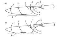
以下、本発明の衝撃を利用した切断器具の各種実施形態について、図面を用いて説明すると、図1に示すのは、衝撃力発生部を持つ切断器具である包丁の例を示すもので、この包丁は、刃部1と衝撃発生部2とバネ性を持つ基部3とバネ性を持つ衝撃発生杆4と衝撃発生用凹部又は衝撃発生用凸部7と衝撃発生用凸部又は衝撃発生用凹部8で構成される。
【0013】
ここで、図1(A)に図示する実施例では、まな板6の上に置かれた漬け物5を切ろうとハンドルを把持して押下して負荷をかけると、衝撃発生用凹部7の上部に位置した衝撃発生用凸部8に負荷がかかり、一定以上の負荷が衝撃発生部2にかかるとバネ性を持つ衝撃発生杆4は刃部1の方向に伸び、衝撃発生用凸部8が2つの衝撃発生用凹部7の上方から下方に山を越えて移動し、結果として図1(B)に図示するように衝撃発生部2が開放され、次に衝撃発生用凸部8が衝撃発生用凹部7の下端に当たり、衝撃が発生し、刃部1に伝わるものであり、勿論、衝撃発生用凸部8と衝撃発生用凹部7とは逆に形成しても構わないものである。
【0014】
そして、図2に図示するものは、鼻毛切りが衝撃発生用凸部9.9a同士の接触により衝撃を発生する実施例を示すもので、この毛切りは、刃部1と切断用刃受け部11と衝撃発生用凸部9と衝撃発生部2とを備えており、毛切りで毛10を切ろうと両側の把持杆を把持すると衝撃発生部2に負荷がかかり、一定以上の負荷が衝撃発生部2にかかると、図4に図示するように、バネ性を持つ衝撃発生部2の凸部支持柄18は左右に動き、衝撃発生用凸部9が下側に、他側の衝撃発生用凸部9aが上側に移動し、結果として衝撃発生部2が開放され、刃部1と切断用刃受け部11が当たるため、衝撃が発生するものである。
【0015】
次に、図3に図示するもののは、毛切りの先端外周端12と肌13の関係を示すもので、毛切り先端外周端12の刃先1、上刃16と下刃17との合計の背丈、つまり、一対の把持杆の先端を閉じた状態での把持杆の対峙する面の間隔15は、刃部1と先端外周端12との間隔14の2倍以内とした毛10を切る毛切りであり、先端外周端12から刃部1を内部に設けており、さらに、刃先先端12が丸みを帯びているため肌13を痛めずに毛10を切ることができるものである。
【0015】
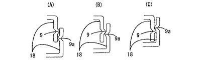
次いで、図4に図示するものは衝撃発生部2の実施例を示し、衝撃発生部2に荷重をかけたときの衝撃発生部2の状態変化を示すもので、図4(A)に図示するものは、切断のための負荷を加える前の状態を表し、一定以上の負荷が衝撃発生部2にかかると、図4(B)に図示するようにバネ性を持つ凸部支持柄18が左右に動き、衝撃発生用凸部9が下側に、他の衝撃発生用凸部9aが上側に移動し、結果として図4(C)に図示するように衝撃発生部2が開放されるものである。
【0016】
更に、図5は衝撃発生部2の次実施例を示し、衝撃発生部2に負荷をかけたときの衝撃発生部2の状態変化を示すもので、図5(A)に図示するものは負荷を加える前の状態を表し、衝撃発生部2に負荷をかけたときに、図5(B)に図示するのようにバネ20によって支持されていた衝撃発生用コロ又は衝撃発生用球状物19が図示する左に移動しようとし、更に一定以上の負荷が衝撃発生部2にかかると、バネ20によって支持されていた衝撃発生用コロ又は衝撃発生用球体19が図示する左に移動し、図5(C)に図示するように衝撃発生部2の負荷が一部開放されるものである。
【0017】
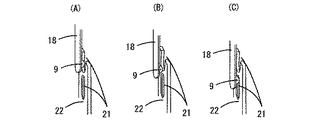
更には、図6に図示するものは、衝撃発生部2の他の実施例を示し、衝撃発生部2に負荷をかけたときの衝撃発生部2の状態変化を示すもので、図6(A)に図示するものは負荷を加える前の状態を表し、一定以上の負荷が衝撃発生部2にかかると、図6(B)に図示するようにバネ性を持つ凸部支持柄18及び凹部支持柄22はそれぞれ、凸部支持柄18が左、凹部支持柄22が右へ動き、衝撃発生用凸部9が下側に、衝撃発生用凹部21が上へ移動し、結果として図6(C)に図示するように衝撃発生部2が開放されるものである。
【0018】
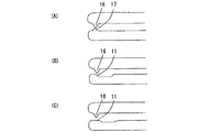
そして、図7に図示するものは、切断器具である毛切りの刃先を外周より内部に入れた状態の刃先と台座の関係の実施例を示しているもので、図7(A)に図示するものは、両刃をとがらせ、上刃16と下刃17との刃先をずらして噛み合わせているものであり、加えて、上刃16と下刃17の刃先の角度を変えているもので、図7(B)に図示するものは、切断用刃受け部11を斜めに窪ませて上刃16と噛み合わせており、図7(C)に図示するものは、切断用刃受け部11を平らにして上刃16と噛み合わせているものである。
【0019】
次に、図8に図示するものは、糸切り、紐切り等の刃先の一例を示す。上刃16と切断用刃受け部11とを備えているものである。
【0020】
図に示していないが、毛切りを含む切断器具の少なくとも人の触れる部分にアレルギー反応の少ないチタン、銀、又は、セラミックを使用することによりアレルギー反応を抑えることができる。
【0021】
【発明の効果】
衝撃力を利用して少ない力で安全に、糸、紐、線材、調理材料等が良く切れる切断器具ができる。また、毛切りを含む切断器具に衝撃力を利用することにより少ない力で確実に切れる毛切りを含む切断器具ができる。肌を挟みにくく、粘膜、肌を痛めない安全な毛切りができる。アレルギー反応を無くすことができる。
【0022】
【図面の簡単な説明】
【図1】本発明に係る衝撃発生部を持つ包丁の実施例である。
【図2】本発明に係る衝撃発生部を持つ毛切りの実施例である鼻毛切りである。
【図3】本発明に係る毛切り時の肌と刃先先端の関係の実施例である。
【図4】本発明に係る凸部同士が接触する衝撃発生部の状態を表す実施例である。
【図5】本発明に係るバネで押さえられたコロ、又は球状物による衝撃発生部の状態を表す実施例である。
【図6】本発明に係る凸部と穴、又は凹部が接触する衝撃発生部の状態を表す実施例である。
【図7】本発明に係る刃先と台座の関係を示す。
【図8】本発明に係る糸切り、紐切り等の刃先の実施例である。
【符号の説明】
1…刃部
2…衝撃発生部
3…基部
4…衝撃発生杆
5…漬け物
6…まな板
7…衝撃発生用凹部又は衝撃発生用凸部
8…衝撃発生用凸部又は衝撃発生用凹部
9…衝撃発生用凸部
10…毛
11…切断用刃受け部
12…先端外周端
13…肌
14…刃部と先端外周端との間隔
15…対峙する面の間隔
16…上刃
17…下刃
18…凸部支持柄
19…衝撃発生用コロ又は衝撃発生用球体
20…バネ
21…衝撃発生用凹部
22…凹部支持柄[0001]
BACKGROUND OF THE INVENTION
The present invention relates to a knife, a knife, or a cutting instrument such as a hair cutter or a thread cutter utilizing an impact force.
[0002]
[Prior art]
Conventionally, scissors and nippers are used to cut yarn, wool, leather, wire, and the like. Also, when cutting boned meat and small fish, scissors are often used instead of knives. Scissors are often pointed and dangerous, and at the same time, the blades open without being cut and can be pinched between the blades. Also, a strong force is necessary. There are times when the last skin remains when cutting pickles etc. with a cutting board. Hair clippers are used to cut hair, and hair removal is used to remove hair. The clipper type is not suitable for fine parts. Tweezers hurt because they pull hair. It also hurts the hair roots. Use scissors when cutting fine hair such as nose hair. Scissors are dangerous when cutting fine hair and can hurt the skin. In general, kitchen knives, scissors, clippers and tweezers are made of materials such as stainless steel and iron, and the surfaces other than stainless steel are often finished by plating with nickel, chromium or the like. These can cause skin allergies.
[0003]
[Problems to be solved by the invention]
The cutting device using the impact of the present invention is a safe device that does not damage mucous membranes and skin with a cutting device that cuts thread, string, wire, cooking material, etc. with weak force and a tool that cuts delicate parts including nose hair. The purpose is to consider allergies with hair cutting.
[0004]
[Means for Solving the Problems]
A cutting instrument using an impact for solving the above-mentioned object is a cutting instrument having a blade portion along the longitudinal direction and a base portion extending to the base end side connected to the handle, and is continuously cut by being extended from the handle. An impact generating rod formed of an elastic member imparted with elasticity on the device side, an impact generating convex portion protruding from the tip of the impact generating rod, and two substantially hemispherical impact generating portions into which the impact generating convex portion is fitted Provided with an impact generating portion composed of a concave portion for use, and further provided with elasticity so that the distal ends of the pair of gripping rods are constantly spaced apart to connect the base end side and also provided a blade portion along the distal end. A cutting instrument comprising an impact generating portion projecting so as to come into contact with a pair of gripping rods, and an impact generating projecting portion projecting at a position where the impact generating portion is located, and a pair of grips A plate-shaped impact generator projecting so as to come into contact with the heel, and the impact generation A projecting portion for generating an impact projecting at a raised position, a projecting projecting portion projecting so as to come into contact with a pair of gripping rods, and projecting on one impact generating unit. And an impact generating recess recessed in the other impact generating portion at a position based on the impact generating convex portion, and protruding from a pair of gripping rods. An impact generating portion having a curved surface and an impact generating roller or impact generating sphere supported by a spring sandwiched by the curved surface of the impact generating portion, and applying a cutting load to the blade portion of the cutting instrument When the impact is generated by the impact generating portion, cutting is easily performed.
[0005]
DETAILED DESCRIPTION OF THE INVENTION
The present invention relates to a knife, a knife, or a cutting instrument such as a hair cutter or a thread cutter using an impact force. The cutting instrument using an impact according to
[0006]
Furthermore, the cutting instrument using the impact according to
[0007]
Furthermore, the cutting instrument using the impact according to
[0008]
In addition, the cutting device using the impact according to claim 4 is provided with elasticity so that the distal ends of the pair of gripping rods opposed to each other are continuously separated to connect the base end side and at least along the distal end side. A cutting instrument having a
[0009]
Furthermore, the cutting device using the impact according to
[0010]
Furthermore, the cutting instrument using the impact according to
[0011]
Furthermore, the cutting device using the impact according to
[0012]
Hereinafter, various embodiments of a cutting instrument using an impact according to the present invention will be described with reference to the drawings. FIG. 1 shows an example of a knife that is a cutting instrument having an impact force generating portion. The knife includes a
[0013]
Here, in the embodiment shown in FIG. 1 (A), when the
[0014]
2 shows an embodiment in which the nose haircut generates an impact by contact between the impact generating convex portions 9.9a, and this haircut has the
[0015]
Next, what is shown in FIG. 3 shows the relationship between the outer
[0015]
Next, what is shown in FIG. 4 shows an embodiment of the
[0016]
Further, FIG. 5 shows a next embodiment of the
[0017]
Further, what is shown in FIG. 6 shows another embodiment of the
[0018]
And what is illustrated in FIG. 7 shows the Example of the relationship between the blade edge | tip and a base in the state which put the blade edge | tip of the hair cutting which is a cutting instrument inside from the outer periphery, and it illustrates in FIG. 7 (A). The thing is that both blades are broken and the blade edges of the
[0019]
Next, what is illustrated in FIG. 8 shows an example of a cutting edge such as thread trimming or string trimming. An
[0020]
Although not shown in the figure, the allergic reaction can be suppressed by using titanium, silver, or ceramic, which has less allergic reaction, on at least the part of the cutting device including the hair cutter that is touched by a person.
[0021]
【The invention's effect】
Using an impact force, a cutting device that can safely cut threads, strings, wires, cooking materials, etc. with less force can be made. Moreover, the cutting instrument containing the hair cutter which cuts reliably with little force can be made by utilizing an impact force for the cutting instrument containing the hair cutter. It is difficult to pinch the skin, and safe hair cutting that does not damage the mucous membranes and skin can be done. Allergic reactions can be eliminated.
[0022]
[Brief description of the drawings]
FIG. 1 is an embodiment of a kitchen knife having an impact generator according to the present invention.
FIG. 2 is a nasal haircut which is an embodiment of a haircut having an impact generating portion according to the present invention.
FIG. 3 is an example of the relationship between the skin and the tip of the cutting edge during hair cutting according to the present invention.
FIG. 4 is an embodiment showing a state of an impact generating portion where convex portions contact with each other according to the present invention.
FIG. 5 is an embodiment showing a state of an impact generating portion by a roller pressed by a spring or a spherical object according to the present invention.
FIG. 6 is an example showing a state of an impact generating portion where a convex portion and a hole or a concave portion contact according to the present invention.
FIG. 7 shows a relationship between a cutting edge and a pedestal according to the present invention.
FIG. 8 is an embodiment of a cutting edge for thread cutting, string cutting or the like according to the present invention.
[Explanation of symbols]
DESCRIPTION OF
Claims (7)
Priority Applications (1)
| Application Number | Priority Date | Filing Date | Title |
|---|---|---|---|
| JP2000333881A JP4739500B2 (en) | 2000-09-26 | 2000-09-26 | Cutting device using impact |
Applications Claiming Priority (1)
| Application Number | Priority Date | Filing Date | Title |
|---|---|---|---|
| JP2000333881A JP4739500B2 (en) | 2000-09-26 | 2000-09-26 | Cutting device using impact |
Publications (3)
| Publication Number | Publication Date |
|---|---|
| JP2002095874A JP2002095874A (en) | 2002-04-02 |
| JP2002095874A5 JP2002095874A5 (en) | 2008-02-21 |
| JP4739500B2 true JP4739500B2 (en) | 2011-08-03 |
Family
ID=18809891
Family Applications (1)
| Application Number | Title | Priority Date | Filing Date |
|---|---|---|---|
| JP2000333881A Expired - Lifetime JP4739500B2 (en) | 2000-09-26 | 2000-09-26 | Cutting device using impact |
Country Status (1)
| Country | Link |
|---|---|
| JP (1) | JP4739500B2 (en) |
Families Citing this family (2)
| Publication number | Priority date | Publication date | Assignee | Title |
|---|---|---|---|---|
| KR100972030B1 (en) | 2010-01-26 | 2010-07-22 | 박호종 | Nose hair cutter |
| KR101976035B1 (en) * | 2017-07-25 | 2019-05-08 | 김승호 | Scissors for cutting the hairs |
Family Cites Families (6)
| Publication number | Priority date | Publication date | Assignee | Title |
|---|---|---|---|---|
| JPS51150851A (en) * | 1975-06-20 | 1976-12-24 | Sochi Shikenjo | Flexible silo |
| JPS54139957A (en) * | 1978-04-24 | 1979-10-30 | Nippon Flour Mills | Quick drying clay composition |
| JPS61161990A (en) * | 1984-10-19 | 1986-07-22 | コルモーゲン コーポレイション | Power supply system for induction device |
| JPH0777966B2 (en) * | 1989-08-26 | 1995-08-23 | 株式会社フジクラ | Method and apparatus for cutting quartz glass rod |
| US5813109A (en) * | 1997-01-21 | 1998-09-29 | Harris Corporation | Impact/no-impact punchdown tool for use with cut/no-cut or wire insertion blade assembly |
| JP3049054B1 (en) * | 1999-04-26 | 2000-06-05 | 川崎重工業株式会社 | Impact generator |
-
2000
- 2000-09-26 JP JP2000333881A patent/JP4739500B2/en not_active Expired - Lifetime
Also Published As
| Publication number | Publication date |
|---|---|
| JP2002095874A (en) | 2002-04-02 |
Similar Documents
| Publication | Publication Date | Title |
|---|---|---|
| US4246698A (en) | Suture remover | |
| US20140325846A1 (en) | Baby Safe Trimming Tool | |
| AU2012258693A1 (en) | Skin removal instrument | |
| US5047037A (en) | Suture removing instrument | |
| JP4739500B2 (en) | Cutting device using impact | |
| JP4231557B2 (en) | Hairdressing methods and instruments | |
| US4315369A (en) | Food cutting and grasping implement | |
| US20230109002A1 (en) | Razor Blade Head and Razor for Use Therewith | |
| US3266493A (en) | Combination surgical instrument for cutting and removing sutures | |
| JP2890251B2 (en) | Safety razor | |
| JP6231710B1 (en) | Tweezer type waste tweezers | |
| US7628161B1 (en) | Hair-cutting and styling device and method of use | |
| KR200409119Y1 (en) | Cleaning device for nails | |
| JP7228215B1 (en) | Razor handle and razor with said razor handle | |
| JP4476922B2 (en) | Surgical insulator | |
| JP4351464B2 (en) | Leather holder | |
| JP2006043377A (en) | Utensil for cracking boiled chestnut | |
| CN219027582U (en) | Small amount white hair trimmer | |
| KR200379487Y1 (en) | Cutter For Unwanted Hair | |
| CN211020056U (en) | Water spinach picking device | |
| JP3085833U (en) | Hair dye brush | |
| US20220183439A1 (en) | Beard and Hair Comb in Shape of Axe | |
| JPH06328367A (en) | Scissoring instrument | |
| JP4041533B2 (en) | Nail orthosis | |
| JP3046909U (en) | Natural friction in hair cutting |
Legal Events
| Date | Code | Title | Description |
|---|---|---|---|
| A711 | Notification of change in applicant |
Free format text: JAPANESE INTERMEDIATE CODE: A711 Effective date: 20070903 |
|
| A521 | Written amendment |
Free format text: JAPANESE INTERMEDIATE CODE: A523 Effective date: 20070925 |
|
| A621 | Written request for application examination |
Free format text: JAPANESE INTERMEDIATE CODE: A621 Effective date: 20070925 |
|
| A521 | Written amendment |
Free format text: JAPANESE INTERMEDIATE CODE: A523 Effective date: 20070907 |
|
| A521 | Written amendment |
Free format text: JAPANESE INTERMEDIATE CODE: A821 Effective date: 20070926 |
|
| A521 | Written amendment |
Free format text: JAPANESE INTERMEDIATE CODE: A523 Effective date: 20071204 |
|
| A977 | Report on retrieval |
Free format text: JAPANESE INTERMEDIATE CODE: A971007 Effective date: 20081023 |
|
| A131 | Notification of reasons for refusal |
Free format text: JAPANESE INTERMEDIATE CODE: A131 Effective date: 20101022 |
|
| A521 | Written amendment |
Free format text: JAPANESE INTERMEDIATE CODE: A523 Effective date: 20101220 |
|
| RD02 | Notification of acceptance of power of attorney |
Free format text: JAPANESE INTERMEDIATE CODE: A7422 Effective date: 20101220 |
|
| TRDD | Decision of grant or rejection written | ||
| A01 | Written decision to grant a patent or to grant a registration (utility model) |
Free format text: JAPANESE INTERMEDIATE CODE: A01 Effective date: 20110405 |
|
| A61 | First payment of annual fees (during grant procedure) |
Free format text: JAPANESE INTERMEDIATE CODE: A61 Effective date: 20110428 |
|
| R150 | Certificate of patent or registration of utility model |
Ref document number: 4739500 Country of ref document: JP Free format text: JAPANESE INTERMEDIATE CODE: R150 Free format text: JAPANESE INTERMEDIATE CODE: R150 |
|
| FPAY | Renewal fee payment (event date is renewal date of database) |
Free format text: PAYMENT UNTIL: 20140513 Year of fee payment: 3 |
|
| R250 | Receipt of annual fees |
Free format text: JAPANESE INTERMEDIATE CODE: R250 |
|
| R250 | Receipt of annual fees |
Free format text: JAPANESE INTERMEDIATE CODE: R250 |
|
| R250 | Receipt of annual fees |
Free format text: JAPANESE INTERMEDIATE CODE: R250 |
|
| S533 | Written request for registration of change of name |
Free format text: JAPANESE INTERMEDIATE CODE: R313533 |
|
| R350 | Written notification of registration of transfer |
Free format text: JAPANESE INTERMEDIATE CODE: R350 |
|
| S802 | Written request for registration of partial abandonment of right |
Free format text: JAPANESE INTERMEDIATE CODE: R311802 |
|
| R350 | Written notification of registration of transfer |
Free format text: JAPANESE INTERMEDIATE CODE: R350 |
|
| R250 | Receipt of annual fees |
Free format text: JAPANESE INTERMEDIATE CODE: R250 |