JP4736331B2 - Acoustic signal playback device - Google Patents
Acoustic signal playback device Download PDFInfo
- Publication number
- JP4736331B2 JP4736331B2 JP2004053714A JP2004053714A JP4736331B2 JP 4736331 B2 JP4736331 B2 JP 4736331B2 JP 2004053714 A JP2004053714 A JP 2004053714A JP 2004053714 A JP2004053714 A JP 2004053714A JP 4736331 B2 JP4736331 B2 JP 4736331B2
- Authority
- JP
- Japan
- Prior art keywords
- sample
- block
- bit
- value
- samples
- Prior art date
- Legal status (The legal status is an assumption and is not a legal conclusion. Google has not performed a legal analysis and makes no representation as to the accuracy of the status listed.)
- Expired - Fee Related
Links
Images


Description
本発明は、インターネット上でBGM(バックグラウンドミュージック)付のホームページ等を製作する場合に好適な音響信号の再生装置に関するものである。 The present invention relates to a sound signal reproducing apparatus suitable for producing a homepage with BGM (background music) on the Internet.
従来より、音響信号の圧縮には様々な手法が用いられている。音響信号を圧縮して符号化する手法として、MP3(MPEG−1/Layer3)、AAC(MPEG−2/Layer3)などが実用化されている。このような圧縮符号化方式により、音響信号を小さいデータとして扱うことが可能となり、データの記録・伝送の効率化に貢献している。 Conventionally, various methods are used for compression of an acoustic signal. As a method for compressing and encoding an acoustic signal, MP3 (MPEG-1 / Layer3), AAC (MPEG-2 / Layer3), and the like have been put into practical use. Such a compression encoding method makes it possible to handle an acoustic signal as small data, and contributes to the efficiency of data recording and transmission.
最近では、上述のようなMP3、AAC等のロッシー符号化方式だけでなく、完全に復元することが可能なロスレス符号化方式も開発されており、音響素材の管理に用いられている(例えば、特許文献1参照)。
しかしながら、上述のような従来のロスレス符号化方式では、途中で条件パラメータの変更が行われず、全体に渡って同一の条件パラメータ符号化が行われている。そのため、区間に応じた条件パラメータを設定することができないという問題がある。また、従来の方式では、符号化対象とする音響信号を一度に読み込まなければならないため、大容量の音響データの符号化が困難である。 However, in the conventional lossless encoding method as described above, the condition parameter is not changed midway, and the same condition parameter encoding is performed throughout. Therefore, there is a problem that the condition parameter corresponding to the section cannot be set. Further, in the conventional method, since the acoustic signal to be encoded must be read at once, it is difficult to encode a large volume of acoustic data.
このため、本出願人は符号化条件パラメータを所定の区間ごとに変更可能であるとともに、大容量のデータであっても符号化することが可能な時系列信号の符号化装置および再生装置を開発している。 For this reason, the present applicant has developed a time-series signal encoding device and reproducing device that can change the encoding condition parameter for each predetermined section and can encode even a large amount of data. is doing.
しかしながら、かかる再生装置は、スタンドアローンの端末装置では、実現可能であるが、インターネット等のネットワークを経由した端末装置側で再生を行うことはできない。 However, such a playback device can be realized with a stand-alone terminal device, but cannot be played back on the terminal device side via a network such as the Internet.
本発明の目的は、前述した問題点に鑑みてなされたもので、その目的とするところはネットワークを経由して音響信号の再生が可能な再生装置を提供することにある。 An object of the present invention has been made in view of the above-described problems, and an object of the present invention is to provide a reproducing apparatus capable of reproducing an acoustic signal via a network.
前述した目的を達成するための第1の発明は、サーバと、端末装置とがネットワークで接続されたシステムにおいて、前記サーバが、符号化により圧縮された音響信号で構成される複数の音楽素材より、再生すべき音楽素材を複数個選択する情報を有するオブジェクトタグを生成する生成手段と、前記オブジェクトタグを、HTML文書の所定の位置に書き込む手段と、を具備し、前記端末装置が、前記HTML文書にアクセスすると、前記オブジェクトタグの記述に従い、選択された複数個の音楽素材に対応する圧縮された音響信号の各々に対して、圧縮ブロックを読み込み、圧縮ブロックを復号化し、復号化された複数の非圧縮ブロックを波形合成して再生する手段と、を具備することを特徴とする音響信号の再生装置である。前記サーバまたは前記端末装置が前記マトリクスを設定できる。
According to a first aspect of the present invention for achieving the above object, in a system in which a server and a terminal device are connected via a network, the server includes a plurality of music materials composed of acoustic signals compressed by encoding. a generating means for generating an object tags having information plurality select the music material to be played, the object tag, comprising means for writing a predetermined position of the HTML document, and said terminal apparatus, said HTML When the document is accessed, in accordance with the description of the object tag , the compressed block is read for each of the compressed audio signals corresponding to the plurality of selected music materials , the compressed block is decoded, and the decoded plural And a means for reproducing the uncompressed block by synthesizing the waveform . The server or the terminal device can set the matrix.
本発明によれば、端末装置がネットワークを経由してサーバにアクセスすると所定の音響信号が再生される。 According to the present invention, when a terminal device accesses a server via a network, a predetermined acoustic signal is reproduced.
(0.1 実施形態の概要)
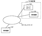
以下、図面に基づいて本発明の好適な実施の形態を詳細に説明する。図1は本実施の形態にかかる音響信号の再生装置が組み込まれたシステムを示す図である。ネットワーク101にウェブサーバ103、端末装置105、端末装置107等が接続されている。
(0.1 Outline of Embodiment)
Hereinafter, preferred embodiments of the present invention will be described in detail with reference to the drawings. FIG. 1 is a diagram showing a system in which a sound signal reproducing apparatus according to this embodiment is incorporated. A
ウェブサーバ103、端末装置105はホームページの製作者109が有する。ウェブサーバ103は製作者109が製作したホームページをインターネット等のネットワーク101を介して提供する。端末装置105はこのホームページ等を製作するために必要なコンピュータ等である。端末装置107は一般ユーザが有するコンピュータ等である。
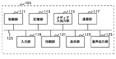
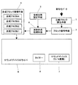
図2は端末装置105の構成を示すブロック図である。端末装置105は、中央処理装置等の制御部111と、HDD等の記憶部113と、フレキシブルディスクやCD−ROM等のメディアの読み込み書き込みを行うメディア入出力部115と、ネットワーク101に接続するモデムやLANボード等の通信部117と、キーボード、マウス又はマイク等の入力部119と、プリンタ等の印刷部121と、CRTや液晶表示装置等の表示部123と、スピーカ等の音声出力部125とから構成され、それぞれがバス125で接続されている。
FIG. 2 is a block diagram showing the configuration of the
図3はウエブサーバ103の構成を示すブロック図である。ウエブサーバ103は、中央処理装置等の制御部131と、HDD等の記憶部133と、フレキシブルディスクやCD−ROM等のメディアの読み込み書き込みを行うメディア入出力部135と、ネットワーク101に接続するモデムやLANボード等の通信部137と、キーボード、マウス又はマイク等の入力部139と、プリンタ等の印刷部141と、CRTや液晶表示装置等の表示部143とから構成され、それぞれがバス147で接続されている。
FIG. 3 is a block diagram showing the configuration of the
端末装置107の構成は、図2に示す端末装置105の構成と同様である。
次に、本実施の形態における端末装置105の処理動作について説明する。図4は端末装置105の処理を示すフローチャートである。端末装置105及び端末装置107には、図4に示す処理を実行するためのプログラムが予めプラグインされている。製作者109がホームページ等を製作する場合、HTML文書を作成する。本実施の形態ではこのHTML文書内に音響信号を再生するプログラムを組み込むことにより、一般ユーザの端末装置107等がホームページにアクセスした場合、画面上に文字情報、画像情報が表示されると同時に、この画面に付随した音響信号がBGMの如く再生される。
The configuration of the
Next, the processing operation of
図4に示す処理は、この音響信号を組み込んだホームページを作成するための端末装置105の処理を示すフローチャートである。
The process shown in FIG. 4 is a flowchart showing the process of the
製作者109の指示に応じて、端末装置105の制御部111は、プレーヤ画面を開く(ステップS401)。すなわち、端末装置105の表示部123には、プラグインされたプログラムに応じて、制御部111が所定の表示を行っている。この画面上で、製作者が所定の指示を行うと、制御部111は、表示部123にプレーヤ画面を表示させる。プレーヤ画面とは、音楽素材を選択するための画面である。
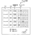
図5は端末装置105の表示部123の一部に表示されたプレーヤ画面151を示す図である。プレーヤ画面151には、トラック種別表示部153、再生非再生表示部155、音量指定部157、マトリクス159が表示される。
In response to an instruction from the producer 109, the
FIG. 5 is a diagram showing a player screen 151 displayed on a part of the
トラック種別表示部153には5つのトラック名が表示される。すなわち、トラック1、トラック2、・・・、トラック5が表示される。
再生非再生表示部155にはトラックが再生される場合と再生されない場合の表示が区別して行われる。
音量指定部157は各トラックの音量を「0」から「100」の数値で指定する。
The track
The reproduction /
The
マトリクス159は5×5のマトリクスであり、「11」、「12」、・・・、「21」、「22」、・・・、「53」、「54」、「55」の25個の要素からなり、一つの要素は一つの音楽素材を表し、各素材は異なるものである。
The
製作者109の指示に従い、制御部111は、マトリクス159の設定を行う(ステップS402)。すなわち製作者109は表示されているマトリクス159に対してマウス等を用いて、各トラックに対して一つの素材を選択すると、制御部111は、例えば、図5に示される場合、「12」、「22」、「31」、「43」、「51」の5つの素材が選択されていることを認識する。
In accordance with the instruction from the producer 109, the
次に、製作者109によりOKボタン161が押されると、制御部111は、プラグインされたプログラムのプレーヤを指定したオブジェクトタグを自動的に生成し、メモリ上のクリップボードにコピーする(ステップS403)。
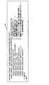
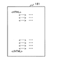
図6はオブジェクトタグを有するHTML16を示す図である。
<object calssid=”player”・・・</object>までがオブジェクトタグの内容である。
calssidはプレーヤとして、プラグインされたプログラムを指すシリアル番号である。
Next, when the producer 109 presses an
FIG. 6 shows an HTML 16 having an object tag.
<object calssid = ”player” ... </ object> is the contents of the object tag.
calssid is a serial number indicating a plugged-in program as a player.
<param name=”autoPlay” value=”On”は自動再生の指定をオンオフするもので、この場合オンが指定されている。
<param name=”Directory” value=”AAAAAA”は素材配置場所を指定するもので、AAAAAAが配置場所を示すURLである。
<param name=”File” value=”ois”は音響素材識別情報の指定を行う。
<param name=”Extention” value=”enc”はロスレス圧縮と非圧縮を指定するもので、encの場合ロスレスが指定され、wavの場合非圧縮が指定される。
<param name = “autoPlay” value = ”On” turns on / off the designation of automatic reproduction, and in this case, on is designated.
<param name = “Directory” value = “AAAAAA” specifies the material placement location, and AAAAAA is a URL indicating the placement location.
<param name = ”File” value = ”ois” specifies acoustic material identification information.
<param name = ”Extention” value = ”enc” specifies lossless compression and non-compression. Lossless is specified for enc, and non- compression is specified for wav.
<param name=”Sector” value=”2,2,1,3,1”は選択される音楽素材のデフォルト値を示すもので、図5に示すように、マトリクス59でトラック1に対して「2」列目が指定され、トラック2に対して「2」列目が指定され、トラック3に対して「1」列目が指定され、トラック4に対して「3」列目が指定され、トラック5に対して「1」列目が指定されるので、デフォルト値として「2、2、1、3、1」が設定される。
このような指定を行うことにより、楽曲に対して編曲を行うことが可能となる。
<param name=”MatrixSize” value=”5”は音楽素材数を示すもので、音響合成するトラック数を示す。
<param name = “Sector” value = “2,2,1,3,1” indicates the default value of the selected music material. As shown in FIG.
By performing such designation, it becomes possible to arrange music.
<param name = “MatrixSize” value = “5” indicates the number of music materials and indicates the number of tracks to be synthesized.
なお、図6に示すように、オブジェクトタグを<div>タグで挟むようにしてもよい。<div>タグは、製作者109によって書き込まれる。
<div>タグはホームページ上で再生装置を示すプレーヤーバーの左上端の位置を示す。図6の場合、上端から40ピクセル、左端から10ピクセルの位置にプレーヤーバーが表示されるような設定となっている。
As shown in FIG. 6, the object tag may be sandwiched between <div> tags. The <div> tag is written by the producer 109.
The <div> tag indicates the position of the upper left corner of the player bar indicating the playback device on the home page. In the case of FIG. 6, the player bar is set to be displayed at a position of 40 pixels from the upper end and 10 pixels from the left end.
図7は図6に示すオブジェクトタグが表示された端末装置105の画面171を示す図であり、オブジェクトタグ等を表示する領域173と、コピーボタン175、ファイル保存ボタン177が表示される。コピーボタン175は領域173のオブジェクトタグをHTML文書の所定の位置にコピーするためのボタンである。ファイル保存ボタン177は領域173に表示されているオブジェクトタグをドラッグアンドドロップすることにより、任意の場所に保存する。HTML文書を作成する前に、編曲を決定したときは、任意のフォルダへオブジェクトタグをファイルとして保存しておくことができる。
FIG. 7 is a diagram showing a screen 171 of the
また、製作者109は端末装置105を用いてテキストエディタでHTML文書181を作成している(ステップS404)。このHTML文書181はホームページを構成するものであり、図8はHTML文書181を示す図である。
図7に示すコピーボタン175が押されると、制御部111は、前述したHTML文書181中にオブジェクトタグをペーストすることができる(ステップS405)。
Further, the producer 109 creates an
When the
図9はオブジェクトタグがペーストされたHTML文書181を示す図である。図9に示すように、HTML文書181にオブジェクトタグを有するHTML162がペーストされ、図10に示すように、端末装置105の表示部123には、ホームページが表示される。ホームページ画面の上端から40ピクセル、左端から10ピクセルの位置にプレーヤーバー185の左上端が来るように表示される。すなわち、<div>タグで示された上端から40ピクセル、左端からから10ピクセルの位置にプレーヤーバー185が表示される。
以上の処理を経て得られたHTML文書181を、製作者109はウェブサーバ103に保存する(ステップ406)。
FIG. 9 is a diagram showing an
The producer 109 stores the
一般ユーザの端末装置107からウェブサーバ3にアクセスし、ホームページを閲覧する場合、図10に示すようなホームページ画面が表示され、プレヤーバー185の音楽再生スイッチ187をクリックすると、オブジェクトタグ162で指定された音響信号が合成されて再生される。
When accessing the
すなわち、オブジェクトタグ162に素材配置場所のURLが記載されているので、そのURLを有するサーバにおいて、編曲のデフォルト値に応じて、素材が選択される。選択された素材は、端末装置107に送られ、プラグインされたプログラムによって合成される。
That is, since the URL of the material arrangement location is described in the
すなわち一般ユーザはホームページの画面を見ると同時に音響信号を聞くことができる。この音響信号は製作者109により予め設定されたものであるが、端末装置107からプレーヤーバー183の設定スイッチ189をクリックすると、プレーヤ画面159が表示され、マトリクス159の設定を端末装置107側で新たに行うことにより、別の編曲を行うことができる。なお、マトリクスの設定に応じて音響信号が再生される処理については後述する。
That is, a general user can listen to an acoustic signal at the same time as viewing a homepage screen. This sound signal is preset by the producer 109, but when the setting
また、図11、図12に示すように、オブジェクトタグ191とメタファイル193を別に設けるようにしてもよい。図11はオブジェクトタグ191を示し、そのオブジェクトタグの中でメタファイル193を指定する。
Further, as shown in FIGS. 11 and 12, an
図12はメタファイル193を示す。このメタファイル193の中には図6に示すような自動再生の指定オンオフや素材配置場所の指定(URL)等が書き込まれている。
FIG. 12 shows the
このように、本実施の形態によれば、ウエブサイト(HTML)の中に、音響信号の再生装置を埋め込むことができる。この再生装置は、CD(コンパクトディスク)以上の高精細な音響信号を再生することができる。 As described above, according to the present embodiment, it is possible to embed a sound signal reproducing device in a website (HTML). This playback apparatus can play back high-definition audio signals of CD (compact disc) or higher.
そして、一般ユーザは、インターネットを介して、サーバにアクセスすることにより音響信号を再生することができ、逆に、サーバ側から言えば、インターネットを介して、音楽ファイルを一般ユーザに配布することができる。
再生される音楽は、サーバ側の製作者によって、編曲することができ、また、ユーザも編曲を指定できる。
The general user can reproduce the sound signal by accessing the server via the Internet. Conversely, from the server side, the music file can be distributed to the general user via the Internet. it can.
The reproduced music can be arranged by the producer on the server side, and the user can also specify the arrangement.
なお、図11、図12に示すように、メタファイルを作成した場合、図13に示すように、画面171には、コピーボタン175と、プレイリスト保存ボタン178が表示される。
プレイリスト保存ボタン178をクリックするとオブジェクトタグ191とメタファイル193が保存される。
As shown in FIGS. 11 and 12, when a metafile is created, a
When the play list save
また、図5に示すプレーヤ画面151において、図14に示すように、マトリクス159の横にファイル指示部を160を設け、マトリクス159を設定する代わりに、ファイル指定部160で音楽素材(再生ファイル)を設定するようにしてもよい。
Also, in the player screen 151 shown in FIG. 5, as shown in FIG. 14, a file instruction unit 160 is provided beside the
図14では、たとえば、トラック3をマトリクス159で指定するのではなく、ファイル指定部160で指定する場合を示す。すなわち、ファイル指定部160のボタン162−3をクリックすると、ダイアログ164が表示され、このダイアログ164中に表示された音楽素材(再生ファイル)を選択する。
なお、トラック3だけでなく、他のトラックについてもファイル指定部160で音楽素材(再生ファイル)を設定するようにしてもよい。
FIG. 14 shows a case in which, for example, the
Note that the music material (reproduction file) may be set by the file designation unit 160 not only for the
次に、本実施の形態に係る音響信号の符号化および再生について詳細に説明する。本再生装置の対象とする符号化データは、以下に示す音響信号の符号化装置により、元の音響信号を圧縮符号化することにより得られる。
なお、この符号化装置は、端末装置105によって実現される。
Next, encoding and reproduction of an acoustic signal according to the present embodiment will be described in detail. The encoded data that is the target of this playback apparatus is obtained by compressing and encoding the original acoustic signal by the acoustic signal encoding apparatus shown below.
This encoding device is realized by the
(1.1符号化装置の構成)
図15は、音響信号の符号化装置の構成図である。図15において、10はブロック分割手段、20は下位固定ビット削除手段、30はチャンネル間演算手段、40はサンプル列再配置手段、50は信号平坦部処理手段、60は相関フレーム検出手段、70は予測誤差変換手段、80は極性処理手段、90は可変長符号化手段、100は符号出力手段である。
(1.1 Configuration of encoding device)
FIG. 15 is a configuration diagram of an audio signal encoding device. In FIG. 15, 10 is a block dividing means, 20 is a low-order fixed bit deleting means, 30 is an inter-channel computing means, 40 is a sample sequence rearranging means, 50 is a signal flat part processing means, 60 is a correlation frame detecting means, and 70 is A prediction error conversion means, 80 is a polarity processing means, 90 is a variable length coding means, and 100 is a code output means.
図15において、ブロック分割手段10はサンプリングにより得られたサンプル列であるデジタル音響信号を、所定のサンプル数に分割してワークメモリに読み込む機能を有している。下位固定ビット削除手段20は、複数の音響信号を合成する際に、ビット数を合わせるために加えられたとみなされる下位の所定数のビットを削除する機能を有している。チャンネル間演算手段30は、複数のチャンネルからなるサンプル列の各チャンネル間の相関演算を行う機能を有する。サンプル列再配置手段40は、ブロックを構成するサンプル列を録音を基に得られたサンプル列である主サンプル列と主サンプル列を補間することにより得られた副サンプル列とに分離する機能を有している。信号平坦部処理手段50は、各チャンネルごとのサンプル列に対して、信号の値が一定である平坦部を検出し、効率的に符号化する機能を有する。 In FIG. 15, the block dividing means 10 has a function of dividing a digital acoustic signal, which is a sample string obtained by sampling, into a predetermined number of samples and reading it into a work memory. The lower fixed bit deletion means 20 has a function of deleting a predetermined number of lower bits considered to have been added to match the number of bits when a plurality of acoustic signals are synthesized. The inter-channel calculation means 30 has a function of performing a correlation calculation between each channel of a sample string composed of a plurality of channels. The sample sequence rearrangement means 40 has a function of separating the sample sequence constituting the block into a main sample sequence which is a sample sequence obtained based on recording and a sub sample sequence obtained by interpolating the main sample sequence. Have. The signal flat part processing means 50 has a function of detecting a flat part having a constant signal value and efficiently encoding the sample sequence for each channel.
相関フレーム検出手段60は、各サンプル列に対して、所定の区間をフレームとして設定した後、フレーム間で対応する全てのサンプル値が同一になっている相関フレームを検出し、時間的に後方(未来)に位置する相関フレームを削除する機能を有する。予測誤差変換手段70は、線形予測誤差の手法を用いて、各サンプルの値を予測誤差値に変換する機能を有する。極性処理手段80は、正負の値を補数表現により表した各サンプルのビット列を、正負の極性を表す1ビットと他のビット列に分ける処理を行う機能を有する。可変長符号化手段90は、各サンプルの値を可変ビット長で符号化する機能を有している。符号出力手段100は、各ブロック単位で符号化されたデータおよび上記各手段により得られるデータを、分割されたブロック形態を維持しながら単一の符号化ファイルに出力する機能を有している。図1に示した装置は、実際には、コンピュータおよびコンピュータにインストールされた専用のソフトウェアプログラムにより実現される。 The correlation frame detection means 60 sets a predetermined section as a frame for each sample sequence, detects a correlation frame in which all corresponding sample values are the same between frames, and is backward in time ( A function of deleting a correlation frame located in the future). The prediction error conversion means 70 has a function of converting the value of each sample into a prediction error value using a linear prediction error method. The polarity processing means 80 has a function of performing processing for dividing a bit string of each sample in which a positive / negative value is represented by a complement expression into one bit representing a positive / negative polarity and another bit string. The variable length encoding means 90 has a function of encoding each sample value with a variable bit length. The code output means 100 has a function of outputting the data encoded in units of each block and the data obtained by the above means to a single encoded file while maintaining the divided block form. The apparatus shown in FIG. 1 is actually realized by a computer and a dedicated software program installed in the computer.
(1.2符号化装置の処理動作)
次に、図15に示した音響信号の符号化装置の処理動作について説明する。まず、ブロック分割手段10が、音響信号を構成するサンプル列の先頭から所定のサンプル数単位でブロック化し、1ブロックごとにワークメモリに読み込む。1ブロックとするサンプル数は、あらかじめ設定しておくことができる。1ブロックとするサンプル数は、音楽の1章節より若干長い程度、すなわち5秒〜10秒程度が好ましい。時間的には同じ長さであっても、サンプリング周波数によりサンプル数が異なるため、設定者が5秒〜10秒程度となるサンプル数をあらかじめ本システムに設定しておく。例えば、符号化対象とする音響信号のサンプリング周波数が48kHzであった場合、1ブロックを10秒とするには、480000サンプルを1ブロックとして設定してやれば良い。ブロック分割手段10は、設定されたサンプル数を1ブロックとして順次ワークメモリに読み込んでいくことになる。
(1.2 Processing operation of encoding device)
Next, the processing operation of the acoustic signal encoding apparatus shown in FIG. 15 will be described. First, the block dividing means 10 blocks in units of a predetermined number of samples from the head of the sample sequence constituting the acoustic signal, and reads it into the work memory for each block. The number of samples for one block can be set in advance. The number of samples for one block is preferably slightly longer than that of the first chapter of music, that is, about 5 to 10 seconds. Even if the length is the same in time, the number of samples varies depending on the sampling frequency, so the setter sets in advance in this system a number of samples that is about 5 seconds to 10 seconds. For example, if the sampling frequency of the acoustic signal to be encoded is 48 kHz, 480000 samples may be set as one block to make one block 10 seconds. The block dividing means 10 sequentially reads the set number of samples as one block into the work memory.
次に、下位固定ビット削除手段20が、1ブロックとして読み込まれたサンプル列の各サンプルの下位の所定数のビットを分離する。これは、量子化ビット数が16ビットのデータを高精細の音響信号と合わせるために24ビットに変換している場合に、冗長な下位ビット成分を削除するために行う。この処理を行わないと、符号化された情報量は3/2倍に増大することになる。また、基になった素材の音響信号が高精細の24ビットで量子化されている場合においても、A/D変換器の性能や編集処理により、冗長な下位ビット成分が特定のブロックのみに発生する場合があり、下位固定ビット削除手段20によりブロック単位で冗長な下位固定ビットの検出と削除を行う処理が有効になることがある。下位ビットが固定でなく有意なデータである場合、下位固定ビットを削除するのではなく分離し、分離された下位ビットデータ配列を出力符号データの一部として別途記録することも可能であり、この場合、後段の予測誤差変換手段70以降の処理負荷が軽減される。この下位固定ビット削除手段20については、動作させるかどうかをあらかじめ設定しておくことができる。
Next, the lower fixed bit deletion means 20 separates a predetermined number of lower bits of each sample of the sample sequence read as one block. This is performed in order to remove redundant lower-order bit components when data having a quantization bit number of 16 bits is converted to 24 bits in order to match a high-definition audio signal. If this process is not performed, the amount of encoded information will increase 3/2 times. In addition, even when the acoustic signal of the underlying material is quantized with high-definition 24-bit data, redundant lower-order bit components are generated only in specific blocks due to the performance of the A / D converter and editing processing. In some cases, the process of detecting and deleting redundant lower fixed bits in units of blocks by the lower fixed
続いて、チャンネル間演算手段30がチャンネル間の相関演算処理を行う。具体的には、まず、同一時刻におけるチャンネルch1のサンプルとチャンネルch2のサンプルの差分演算を行い、差分値をチャンネルch2の新たなサンプル値として記録する。すなわち、元のチャンネルch1のサンプル値をxL、元のチャンネルch2のサンプル値をxRとすると、xch2=xL−xRで算出されたxch2がチャンネルch2のサンプルの新たな値となる。ただし、1ブロックに渡ってxch2の絶対値の総和を算出し、それが、元のチャンネルch2のサンプル値の絶対値の総和よりも大きくなった場合は、チャンネルch2のサンプル値の変更は行わない。これは、本発明がデータの圧縮を目的としているため、データ量が大きくなってしまうと意味がないからである。チャンネルch2の更新が行われたら、チャンネルch1のサンプルの新たな値を算出する。具体的には、算出されたチャンネルch2の新たなサンプル値であるxch2を用いて、xch1=xR+xch2/2で算出する。算出されたxch1がチャンネルch1の新たなサンプル値として記録される。新たなサンプル値xch1は、数学的には、(xL+xR)/2となるが、このようにするとコンピュータによる演算で誤差が生じてしまうため、一旦xch2を算出した後、xch1の算出を行う。 Subsequently, the inter-channel calculation means 30 performs a correlation calculation process between the channels. Specifically, first, the difference calculation between the sample of channel ch1 and the sample of channel ch2 at the same time is performed, and the difference value is recorded as a new sample value of channel ch2. That is, the sample values x L of the original channel ch1, the sample values of the original channel ch2 and x R, and a new value of the sample x ch2 = x L -x x ch2 calculated in R is the channel ch2 Become. However, if the sum of the absolute values of x ch2 is calculated over one block and it is larger than the sum of the absolute values of the sample values of the original channel ch2, the sample value of the channel ch2 is changed. Absent. This is because the present invention is intended for data compression, and therefore it does not make sense to increase the amount of data. When the channel ch2 is updated, a new value of the channel ch1 sample is calculated. Specifically, x ch1 = x R + x ch2 / 2 is calculated using x ch2 which is the new sample value of the calculated channel ch2. The calculated x ch1 is recorded as a new sample value of the channel ch1. The new sample value x ch1 is mathematically (x L + x R ) / 2, but if this is done, an error will occur in the calculation by the computer. Therefore, after calculating x ch2 once, x ch1 Is calculated.
このようにして得られた各チャンネルのサンプル列からは、復号時には、以下のようにすることにより復元することができる。まず、xR=xch1−xch2/2として元のチャンネルch2のサンプル値を復元する。続いて、復元したチャンネルch2のサンプル値xRを用いて、xL=xR+xch2により元のチャンネルch1のサンプル値を復元する。 From the sample string of each channel obtained in this way, at the time of decoding, it can be restored as follows. First, to restore the sample values of the original channel ch2 as x R = x ch1 -x ch2 / 2. Subsequently, using the sample values x R channel ch2 restored by x L = x R + x ch2 restores the sample values of the original channel ch1.
チャンネル間演算手段30による処理が終わったら、サンプル列再配置手段40がサンプル列の再配置処理を行う。サンプル列再配置手段40による処理は、音響信号として複数の音響信号をミックスしたワークデータを扱う場合に有効である。具体的には、サンプリング周波数48kHz、量子化ビット数16ビットの通常の音響信号や、サンプリング周波数96kHz、量子化ビット数24ビットの高精細の音響信号が混在したものである。このようにサンプリング周波数の異なる音響信号を混在させることにより得られる音響信号は、高精細の音響信号にサンプリング周波数を統一させて扱うことになる。この場合、サンプリング周波数48kHzの音響信号は、サンプリング周波数96kHzの音響信号にサンプル数を合わせるべく隣接するサンプルの平均値などで間を補間していく。 When the processing by the inter-channel operation means 30 is finished, the sample row rearrangement means 40 performs sample row rearrangement processing. The processing by the sample row rearrangement means 40 is effective when handling work data in which a plurality of acoustic signals are mixed as acoustic signals. Specifically, a normal acoustic signal having a sampling frequency of 48 kHz and a quantization bit number of 16 bits and a high-definition acoustic signal having a sampling frequency of 96 kHz and a quantization bit number of 24 bits are mixed. The acoustic signal obtained by mixing acoustic signals having different sampling frequencies in this way is handled by unifying the sampling frequency into a high-definition acoustic signal. In this case, an acoustic signal with a sampling frequency of 48 kHz is interpolated with an average value of adjacent samples to match the number of samples with the acoustic signal with a sampling frequency of 96 kHz.
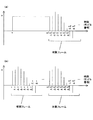
このような音響信号を模式的に示すと図16(a)のようになる。図16(a)において括弧内の数字は、1から昇順に付されたサンプル番号であり、xは、そのサンプルの値を示している。このようなサンプル列に対して、サンプル列再配置手段40は、4通りの処理を行う。1つ目は、奇数番目のサンプルについて、その両隣の偶数番目のサンプルの平均値との差分を演算する。2つ目は、偶数番目のサンプルについて、その両隣の奇数番目のサンプルの平均値との差分を演算する。3つ目は、奇数番目のサンプルについて、直前の偶数番目のサンプルとの差分を演算する。4つ目は、偶数番目のサンプルについて、直前の奇数番目のサンプルとの差分を演算する。各演算後のサンプル列を模式的に示すと、それぞれ図16(b)〜(e)に示すようになる。なお、図16(b)(d)の例では、演算を行わない偶数番目のサンプルを、図16(c)(e)の例では、奇数番目のサンプルを、それぞれ時間的に過去に移動させた状態で示している。 Such an acoustic signal is schematically shown in FIG. In FIG. 16A, the numbers in parentheses are sample numbers assigned in ascending order from 1, and x indicates the value of the sample. For such a sample sequence, the sample sequence rearrangement means 40 performs four types of processing. The first is to calculate the difference between the odd-numbered samples and the average value of the even-numbered samples on both sides. Second, the difference between the even-numbered samples and the average value of the odd-numbered samples on both sides is calculated. The third is to calculate the difference between the odd-numbered sample and the previous even-numbered sample. Fourth, the difference between the even-numbered sample and the immediately preceding odd-numbered sample is calculated. The sample rows after each calculation are schematically shown in FIGS. 16B to 16E, respectively. In the examples of FIGS. 16B and 16D, even-numbered samples that are not subjected to calculation are moved in the past, and in the examples of FIGS. 16C and 16E, odd-numbered samples are moved in the past. It is shown in the state.
この差分演算の結果、差分値が小さいものが最多となるものを副サンプル列とし、その場合に演算を行わないものを主サンプル列とする。図16の例では、図16(b)〜図16(e)の配列の後半分の各値を比較することになる。例えば、奇数番目のサンプルが両隣接サンプルを利用した補間によって得られたものである場合、図16(b)に示した配列の後半の値が0になる。また、偶数番目のサンプルが両隣接サンプルを利用した補間によって得られたものである場合、図16(c)に示した配列の後半の値が0に近くなる。また、奇数番目のサンプルが直前のサンプルと同一の値で補間されたものである場合、図16(d)に示した配列の後半の値が0になる。また、偶数番目のサンプルが直前のサンプルと同一の値で補間されたものである場合、図16(e)に示した配列の後半の値が0になる。例えば、図16(b)に示す配列の後半に0近辺の値が多い場合、偶数番目のサンプルの集合を主サンプル列、奇数番目のサンプルの集合を副サンプル列として分離する。 As a result of this difference calculation, the sample having the smallest difference value is the sub sample sequence, and the sample that is not calculated in this case is the main sample sequence. In the example of FIG. 16, the values in the latter half of the arrays in FIGS. 16B to 16E are compared. For example, when the odd-numbered sample is obtained by interpolation using both adjacent samples, the latter half of the array shown in FIG. When the even-numbered sample is obtained by interpolation using both adjacent samples, the latter half of the array shown in FIG. When the odd-numbered sample is interpolated with the same value as the immediately preceding sample, the latter half of the array shown in FIG. When the even-numbered sample is interpolated with the same value as the immediately preceding sample, the latter half of the array shown in FIG. For example, when there are many values near 0 in the second half of the array shown in FIG. 16B, the set of even-numbered samples is separated as a main sample column, and the set of odd-numbered samples is separated as a sub-sample column.
また、サンプル列再配置手段40の処理においては、図16(b)〜(e)に示したように主サンプルを時間的に過去に移動し、副サンプルを時間的に未来に移動させるようにしても良いが、主サンプルと副サンプルを分離して扱うようにしても良い。例えば、奇数番目が副サンプルの場合には、図16(f)に示すように主サンプルと副サンプルを分離する。本実施形態では、本来のサンプルを利用して補間することにより得られたサンプルを含んだサンプル列に対して線形予測を行うことにより、逆にデータ量が増えてしまうことを防ぐために、主サンプル列と副サンプル列を区別している。そのため、主サンプル列と副サンプル列に対して、別々に線形予測を行うことができれば、図16(b)〜(e)に示したような1つのサンプル列であっても、図16(f)に示したような2つのサンプル列であっても良い。 Further, in the processing of the sample row rearranging means 40, as shown in FIGS. 16B to 16E, the main sample is moved in the past in time and the sub sample is moved in the future in time. However, the main sample and the sub sample may be separated and handled. For example, when the odd number is a sub sample, the main sample and the sub sample are separated as shown in FIG. In this embodiment, in order to prevent the amount of data from increasing due to performing linear prediction on the sample sequence including the sample obtained by interpolation using the original sample, the main sample is used. Distinguish columns from subsample columns. Therefore, if linear prediction can be performed separately for the main sample sequence and the sub sample sequence, even if one sample sequence as shown in FIGS. Two sample rows as shown in FIG.
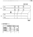
次に、信号平坦部処理手段50が、サンプル列に対して、信号平坦部の処理を行う。信号平坦部とは、同一の信号レベルが連続する部分のことをいう。特に信号レベルが「0」の無音部、および信号レベルの絶対値が最大の飽和部に現れることが多い。無音部は実際に無音であるか、音が非常に小さく記録されなかった場合に生じるが、飽和部は、信号の録音およびA/D変換の過程において生じる。無音部、飽和部またはそれ以外の同一信号レベルが連続する場合のいずれであっても、信号平坦部は、同一の信号レベルが所定の時間(所定のサンプル数)連続して記録される。このため、この部分は圧縮し易いデータになっている。具体的には、信号平坦部の先頭時刻位置と、同一信号レベルが続くサンプルの個数と、信号レベル(サンプル値)の3つの値を信号平坦部データとして各チャンネルのサンプル列と分離して記録する。各チャンネルのサンプル列からは、信号平坦部が削除される。これを模式的に示すと図17(a)(b)に示すようになる。図17(a)は、信号平坦部処理前のサンプル列である。図17(a)において、網掛けで示した部分は信号平坦部を示す。信号平坦部処理手段50の処理により、信号平坦部は元のサンプル列からは分離され、図17(b)に示すようになる。ただし、復号時に元通りに復元するために、分離された信号平坦部は、図17(c)に示すような形式で記録しておく。
Next, the signal flat
信号平坦部データは、上述のように、信号平坦部ごとに、その先頭時刻(サンプル番号)、サンプル数、サンプル値の3属性で記録する。ここで、先頭時刻とは、信号の開始位置からの時刻であり、図17(c)の例では、先頭からのサンプル番号で記録している。上述のように、サンプル番号をサンプリング周波数で除算すれば、時刻に変換されることになる。サンプル数は、そのサンプル値がどの程度連続して続くかを示す情報である。なお、サンプル数の代わりに信号平坦部の終了時刻を記録するようにしても良い。サンプル値は、デジタル化された信号レベルを示している。ここでは、16ビットで量子化しているので、最大値は「32767」、最小値は「−32768」となる。すなわち、「0」は無音部、「32767」および「−32768」は飽和部を示している。ただし、信号平坦部を無条件には処理しない。ここでは、データの圧縮を目的としているため、サンプル列の削減分よりも信号平坦部データが大きくなると意味がないからである。したがって、信号平坦部となるサンプルが所定数以上連続する場合に限り信号平坦部データを作成して各チャンネルのサンプル列から分離するのである。 As described above, the signal flat portion data is recorded for each signal flat portion with the three attributes of the start time (sample number), the number of samples, and the sample value. Here, the head time is the time from the start position of the signal, and in the example of FIG. 17C, it is recorded with the sample number from the head. As described above, when the sample number is divided by the sampling frequency, it is converted into time. The number of samples is information indicating how long the sample value continues. Note that the end time of the signal flat portion may be recorded instead of the number of samples. The sample value indicates the digitized signal level. Here, since quantization is performed with 16 bits, the maximum value is “32767” and the minimum value is “−32768”. That is, “0” indicates a silent portion, and “32767” and “−32768” indicate a saturated portion. However, the signal flat portion is not unconditionally processed. This is because the purpose is to compress the data, and it is meaningless if the signal flat portion data becomes larger than the reduction amount of the sample string. Therefore, the signal flat portion data is generated and separated from the sample sequence of each channel only when a predetermined number or more of samples serving as the signal flat portion are continuous.
続いて、各チャンネルのサンプル列に対して、相関フレーム検出手段60が、所定の区間長をもつフレームを設定して、設定されたフレーム間の比較を行う。本実施形態では、フレーム長をサンプル列の開始時刻から終了時刻までの全区間に渡って固定長としている。具体的には、1フレームを512サンプルとしている。相関フレーム検出手段60は、各チャンネルのサンプル列の先頭から512サンプルずつ1フレームとして設定し、フレーム間で全サンプルが一致する相関フレームを求めていくことになる。具体的な手順を図18のフローチャートに従って説明する。 Subsequently, the correlation frame detection means 60 sets a frame having a predetermined section length for the sample string of each channel, and compares the set frames. In this embodiment, the frame length is fixed over the entire interval from the start time to the end time of the sample string. Specifically, one frame is 512 samples. Correlation frame detection means 60 sets 512 samples from the head of the sample sequence of each channel as one frame, and obtains a correlation frame in which all samples match between frames. Specific procedures will be described with reference to the flowchart of FIG 8.
まず、相関フレーム検出手段60は、所定のサンプル数単位でフレーム化を行う(ステップS1)。本実施形態では、どのブロックにおいてもフレーム長を固定長512サンプルとしている。相関フレーム検出手段60は、図19(a)に示すように、各ブロックにおいて、サンプル列の先頭から512サンプルずつを1フレームとして設定していくことになる。 First, the correlation frame detection means 60 performs framing in units of a predetermined number of samples (step S1). In this embodiment, the frame length is fixed length 512 samples in any block. As shown in FIG. 19A, the correlation frame detecting means 60 sets 512 samples from the head of the sample sequence as one frame in each block.
次に、各フレームに対して構成するサンプル値が全て一致するフレームを探索する。具体的には、図19(b)に示すように、まず、設定されたフレームのうち、ブロック内の時間的に最後尾のフレームを、相関フレームを探すための対象フレームとする。次に、所定の探索範囲内において、対象フレームの先頭サンプルの値と同一の値をもつサンプルを、時間的に遡りながら探索していく(ステップS2)。例えば、図20(a)に示すように、対象フレームがmT〜mT+511の512個のサンプルで構成されているとする。この場合、まず、対象フレームの先頭サンプルmTのサンプル値x(mT)と同一となるサンプルを探索していく。さらに、サンプルmT−1、サンプルmT−2と順に探索していく。なお、図6において、mは先頭からm番目のフレームであることを示し、Tはフレーム長(本実施形態では512サンプル)を示している。 Next, a search is made for a frame in which all sample values constituting each frame match. Specifically, as shown in FIG. 19B, first, among the set frames, the last frame in time in the block is set as a target frame for searching for a correlation frame. Next, within a predetermined search range, a sample having the same value as the value of the first sample of the target frame is searched while going back in time (step S2). For example, as shown in FIG. 20A, it is assumed that the target frame is composed of 512 samples mT to mT + 511. In this case, first, a sample that is the same as the sample value x (mT) of the first sample mT of the target frame is searched. Further, the search is performed in order of the sample mT-1 and the sample mT-2. In FIG. 6, m indicates the m-th frame from the beginning, and T indicates the frame length (512 samples in this embodiment).
一致するサンプルtが見つかったら(ステップS3)、次に、そのサンプルtの次のサンプルt+1と対象フレームの2番目のサンプルmT+1が一致するかどうかを比較する。このようにしてサンプルの値が一致する限り後続するサンプル同士の比較を行っていく(ステップS4)。ステップS4においては、x(t+p)とx(mT+p)の値が一致する限り、処理を繰り返していく。例えば、図20(b)に示す例では、x(t)〜x(t+8)がx(mT)〜x(mT+8)と一致しているので、さらにp=9として、ステップS4の処理が続けられることになる。p=0〜p=511までの全てのx(t+p)とx(mT+p)が一致した場合(ステップS5)、そのサンプル列を対象フレームに対する相関フレームとし、相関フレームの先頭のサンプル番号と対象フレームの先頭のサンプル番号とを対応付けてフレーム相関データとして記録し、対象フレームを元のサンプル列から削除する(ステップS6)。対象フレームの全サンプルと一致しなければ、さらに対象フレームの先頭サンプルと値が一致するサンプルが存在するかどうかを時間的に遡りながら探索していく。所定のサンプル数分遡っても一致する相関フレームが存在しない場合は、その対象フレームに関する相関フレームの探索を中止し、対象フレームの直前のフレームを新たな対象フレームとして相関フレームの探索を行う。1つの対象フレームに対しての処理が終わったら、ステップS2に戻って、1つ直前のフレームを新たな対象フレームとして処理を続けていく(ステップS7)。このようにして、ブロック内の先頭サンプル近辺に位置するフレームを除く全フレームを対象フレームとして相関フレームの検出処理を行う。 If a matching sample t is found (step S3), it is then compared whether the next sample t + 1 of the sample t matches the second sample mT + 1 of the target frame. In this way, as long as the sample values match, the subsequent samples are compared (step S4). In step S4, the process is repeated as long as the values of x (t + p) and x (mT + p) match. For example, in the example shown in FIG. 20B, since x (t) to x (t + 8) coincide with x (mT) to x (mT + 8), the process of step S4 is continued with p = 9. Will be. If all x (t + p) and x (mT + p) from p = 0 to p = 511 match (step S5), the sample string is set as a correlation frame for the target frame, and the first sample number of the correlation frame and the target frame Is recorded as frame correlation data in association with the first sample number, and the target frame is deleted from the original sample sequence (step S6). If it does not match all the samples of the target frame, the search is further made in time to determine whether there is a sample whose value matches the first sample of the target frame. If there is no matching correlation frame even after a predetermined number of samples, the search for the correlation frame related to the target frame is stopped, and the correlation frame search is performed using the frame immediately before the target frame as a new target frame. When the processing for one target frame is completed, the process returns to step S2, and the processing is continued using the immediately previous frame as a new target frame (step S7). In this way, correlation frame detection processing is performed using all frames except for a frame located in the vicinity of the first sample in the block as target frames.
ブロック内のサンプル列全体でみると、図19(c)に示すように対象フレームに対応する相関フレームが検出されたとすると、図19(d)に示すように対象フレームが削除されることになる。このとき、復号時に完全に復元できるように図19(e)に示すようなフレーム相関データが記録される。図19(e)に示すように、フレーム相関データには対象フレームの先頭のサンプル番号と相関フレームの先頭のサンプル番号が対応づけて記録される。 Looking at the entire sample sequence in the block, if a correlation frame corresponding to the target frame is detected as shown in FIG. 19 (c), the target frame is deleted as shown in FIG. 19 (d). . At this time, frame correlation data as shown in FIG. 19E is recorded so that it can be completely restored at the time of decoding. As shown in FIG. 19 (e), in the frame correlation data, the head sample number of the target frame and the head sample number of the correlation frame are recorded in association with each other.
続いて、サンプル列(サンプル列再配置手段40による処理を行った場合は主サンプル列、副サンプル列)の各サンプルの値を、予測誤差変換手段70が予測誤差値に変換する。あるサンプルにおける予測誤差値の算出は、時間的に過去に位置する直前の1つもしくは複数のサンプルの値を利用して行われる。本実施形態では、利用する直前のサンプル数を動的に変化させる手法を用いている。以下に、このような適応型線形予測符号化について説明する。予測誤差変換手段70により行われる適応型線形予測符号化の処理概要を図21のフローチャートに示す。まず、あらかじめ準備された複数の予測計算式を用いて、各予測計算式に対応した線形予測誤差を算出する(ステップS11)。具体的には、サンプル番号tの予測誤差を算出する予測計算式として、以下の〔数式1〕〜〔数式11〕を用意している。
Subsequently, the prediction
〔数式1〕
e0(t)=x(t)−e0(t−1)/2
[Formula 1]
e0 (t) = x (t) -e0 (t-1) / 2
〔数式2〕
e1(t)=x(t)−a11・x(t−1)−e1(t−1)/2
[Formula 2]
e1 (t) = x (t ) -a 11 · x (t-1) -e1 (t-1) / 2
〔数式3〕
e2(t)=x(t)−a21・x(t−1)−a22・x(t−2)−e2(t−1)/2
[Formula 3]
e2 (t) = x (t ) -a 21 · x (t-1) -a 22 · x (t-2) -e2 (t-1) / 2
〔数式4〕
e3(t)=x(t)−a31・x(t−1)−a32・x(t−2)−a33・x(t−3)−e3(t−1)/2
[Formula 4]
e3 (t) = x (t ) -a 31 · x (t-1) -a 32 · x (t-2) -a 33 · x (t-3) -e3 (t-1) / 2
〔数式5〕
e4(t)=x(t)−a41・x(t−1)−a42・x(t−2)−a43・x(t−3)−a44・x(t−4)−e4(t−1)/2
[Formula 5]
e4 (t) = x (t ) -a 41 · x (t-1) -a 42 · x (t-2) -a 43 · x (t-3) -a 44 · x (t-4) - e4 (t-1) / 2
〔数式6〕
e5(t)=x(t)−a51・x(t−1)−a52・x(t−2)−a53・x(t−3)−a54・x(t−4)−a55・x(t−5)−e5(t−1)/2
[Formula 6]
e5 (t) = x (t ) -a 51 · x (t-1) -a 52 · x (t-2) -a 53 · x (t-3) -a 54 · x (t-4) - a 55 · x (t−5) −e5 (t−1) / 2
〔数式7〕
e6(t)=x(t)−b11・x(t−1)−e6(t−1)/2
[Formula 7]
e6 (t) = x (t ) -
〔数式8〕
e7(t)=x(t)−b21・x(t−1)−b22・x(t−2)−e7(t−1)/2
[Formula 8]
e7 (t) = x (t ) -
〔数式9〕
e8(t)=x(t)−b31・x(t−1)−b32・x(t−2)−b33・x(t−3)−e8(t−1)/2
[Formula 9]
e8 (t) = x (t ) -
〔数式10〕
e9(t)=x(t)−b41・x(t−1)−b42・x(t−2)−b43・x(t−3)−b44・x(t−4)−e9(t−1)/2
[Formula 10]
e9 (t) = x (t ) -
〔数式11〕
e10(t)=x(t)−b51・x(t−1)−b52・x(t−2)−b53・x(t−3)−b54・x(t−4)−b55・x(t−5)−e10(t−1)/2
[Formula 11]
e10 (t) = x (t ) -
上記〔数式1〕〜〔数式11〕において、e0(t)〜e10(t)は各予測計算式による時刻tのサンプルにおける予測誤差であり、x(t)〜x(t−5)は時刻t〜t−5におけるサンプル値である。 In the above [Equation 1] to [Equation 11], e0 (t) to e10 (t) are prediction errors in the sample at time t according to each prediction calculation formula, and x (t) to x (t-5) are times. It is a sample value in t-t-5.
上記〔数式3〕における「a21・x(t−1)+a22・x(t−2)」、上記〔数式4〕における「a31・x(t−1)+a32・x(t−2)+a33・x(t−3)」、上記〔数式5〕における「a41・x(t−1)+a42・x(t−2)+a43・x(t−3)+a44・x(t−4)」、上記〔数式6〕における「a51・x(t−1)+a52・x(t−2)+a53・x(t−3)+a54・x(t−4)+a55・x(t−5)」、上記〔数式8〕における「b21・x(t−1)+b22・x(t−2)」、上記〔数式9〕における「b31・x(t−1)+b32・x(t−2)+b33・x(t−3)」、上記〔数式10〕における「b41・x(t−1)+b42・x(t−2)+b43・x(t−3)+b44・x(t−4)」、上記〔数式11〕における「b51・x(t−1)+b52・x(t−2)+b53・x(t−3)+b54・x(t−4)+b55・x(t−5)」は過去の2〜5個のサンプルに基づく線形予測成分である。この線形予測成分、および、直前のサンプルにおいて算出された予測誤差「e1(t−1)/2」〜「e10(t−1)/2」(誤差フィードバック成分)を用いて時刻tにおける予測誤差e0(t)〜e10(t)を算出する。 “A 21 · x (t−1) + a 22 · x (t−2)” in [Expression 3], and “a 31 · x (t−1) + a 32 · x (t−) in [Expression 4]. 2) + a 33 · x (t−3) ”,“ a 41 · x (t−1) + a 42 · x (t−2) + a 43 · x (t−3) + a 44 · x (t−4) ”,“ a 51 · x (t−1) + a 52 · x (t−2) + a 53 · x (t−3) + a 54 · x (t−4) ”in [Formula 6] ) + A 55 · x (t−5) ”,“ b 21 · x (t−1) + b 22 · x (t−2) ”in the above [Formula 8],“ b 31 · x in the above [Formula 9] (T−1) + b 32 · x (t−2) + b 33 · x (t−3) ”,“ b 41 · x (t−1) + b 42 · x (t−2) ”in [Expression 10] above. + B 43・x (t−3) + b 44 · x (t−4) ”,“ b 51 · x (t−1) + b 52 · x (t−2) + b 53 · x (t−3) ” ) + B 54 · x (t−4) + b 55 · x (t−5) ”is a linear prediction component based on the past 2 to 5 samples. Using this linear prediction component and the prediction errors “e1 (t−1) / 2” to “e10 (t−1) / 2” (error feedback component) calculated in the immediately preceding sample, a prediction error at time t e0 (t) to e10 (t) are calculated.
上記の係数a11〜a55には初期値として、a11=1、a21=2、a22=−1、a31=3、a32=−3、a33=1、a41=4、a42=−6、a43=4、a44=−1、a51=5、a52=−10、a53=10、a54=−5、a55=1という値が各々設定されており、上記の係数b11〜b55には初期値として、b11=1、b21=2、b22=−1、b31=3、b32=−3、b33=1、b41=4、b42=−6、b43=4、b44=−1、b51=5、b52=−10、b53=10、b54=−5、b55=1という値が各々設定されている。本実施形態では、これらの係数を設定されたモードに応じて動的に変化させる。図22に本システムで設定可能な線形係数の設定モードを示す。図22において、「初期固定値」とはブロック内の全サンプルについて上記初期値をそのまま用いることを示している。「初期最適値算出」とは、ブロック内のサンプル列全体を通して最適な値を算出し、算出した値をブロック内の全サンプルについて用いることを示している。「ユーザ設定初期固定値」とは、ユーザが独自に設定した値をブロック内の全サンプルについて用いることを示している。「逐次最適値算出」とは、上記初期値を利用して所定のサンプル数単位で係数を更新していくことを示している。本実施形態では、モード2を利用してaij系列の係数を「初期固定値」とし、bij系列の係数を「逐次最適値算出」とする。ここで、「逐次最適値算出」について説明する。「逐次最適値算出」は、具体的には、Levinson-Durvinのアルゴリズムを利用した以下の〔数式12〕を用いて係数b11〜b55を決定する。
As an initial value in the
〔数式12〕
φ(k)=1/(N−K)・Σj=1,N−Kx(j)・x(j+k)
ki=−{φ(i)+Σj=1,i−1bj(i-1)・φ(i-j)}/E(i-1)
bi(i)=ki
bj(i)=bj(i-1)+ki・bi−j(i-1) ただし、1≦j≦i−1
E(i)=(1−ki 2)E(i−1)
[Formula 12]
φ (k) = 1 / (NK) · Σ j = 1, NK x (j) · x (j + k)
k i = − {φ (i) + Σ j = 1, i−1 b j (i−1) · φ (i−j)} / E (i−1)
b i (i) = k i
b j (i) = b j (i−1) + k i · b i−j (i−1) where 1 ≦ j ≦ i−1
E (i) = (1−k i 2 ) E (i−1)
上記〔数式12〕において、φ(k)は、N個のサンプルx(j)(j=1,…,N)において、最大値K(上記例では5)の範囲でkサンプルシフトさせたサンプル列との自己相関値である。なお、NはKに対して十分大きな数値をとっている(例えばK=5の場合、N=32768)。〔数式12〕は、i=1からi=Kまで再帰的に繰り返し、最終的に得られたbj(K)が過去K個のサンプルに対応する係数になるとともに、各フェーズにおいて得られた中間結果であるbj(i)が係数bijとなる。ステップS1においては、上記〔数式12〕により決定した係数を用いて、〔数式7〕〜〔数式11〕の各計算式で計算を行うことになる。〔数式12〕による計算は、実際には後述するステップS17において行われるものである。また、係数を決定するには、過去の数サンプル分の値を必要とするので、初めのN−1サンプルについては、上記の初期係数で〔数式7〕〜〔数式11〕の計算を行うことになる。 In the above [Equation 12], φ (k) is a sample shifted by k samples within the range of the maximum value K (5 in the above example) in N samples x (j) (j = 1,..., N). The autocorrelation value with the column. Note that N is a sufficiently large value with respect to K (for example, when K = 5, N = 32768). [Formula 12] is recursively repeated from i = 1 to i = K, and finally obtained b j (K) is a coefficient corresponding to the past K samples, and is obtained in each phase. The intermediate result b j (i) is the coefficient b ij . In step S1, using the coefficients determined by the above [Equation 12], calculation is performed using the equations [Equation 7] to [Equation 11]. The calculation according to [Equation 12] is actually performed in step S17 described later. In addition, since the values for several past samples are required to determine the coefficient, the first N-1 samples should be calculated using the above initial coefficients [Formula 7] to [Formula 11]. become.
図21のフローチャートに戻って、上記各予測計算式別の予測誤差値の絶対値の累積である累積誤差が最小となる線形予測誤差をそのサンプルの予測誤差として選出する(ステップS12)。ここでは、累積誤差という考え方を用いている。具体的には、各予測計算式〔数式1〕〜〔数式11〕により算出された予測誤差の過去のサンプルについての累積値をA0〜A10として設定する。そして、この累積誤差A0〜A10のうち、最小となるものに対応する予測誤差を選出する。例えば、A0〜A10のうち、A2が最小であったとする。この場合、〔数式3〕で算出された予測誤差e2(t)を符号化対象とする予測誤差e(t)として選出することになる。選出された予測誤差e(t)はサンプルの元の値x(t)と置き換えられて以降処理が行われることになる。 Returning to the flowchart of FIG. 21, the linear prediction error that minimizes the cumulative error, which is the cumulative absolute value of the prediction error value for each prediction calculation formula, is selected as the prediction error of the sample (step S12). Here, the concept of cumulative error is used. Specifically, the cumulative values of the past samples of the prediction error calculated by each prediction calculation formula [Formula 1] to [Formula 11] are set as A0 to A10. Then, a prediction error corresponding to the smallest one of the accumulated errors A0 to A10 is selected. For example, it is assumed that A2 is the smallest among A0 to A10. In this case, the prediction error e2 (t) calculated by [Formula 3] is selected as the prediction error e (t) to be encoded. The selected prediction error e (t) is replaced with the original value x (t) of the sample and the subsequent processing is performed.
続いて、累積誤差A0〜A10に各予測誤差e0(t)〜e10(t)の絶対値を加算する(ステップS13)。具体的には、以下の〔数式13〕に示すように、累積誤差値となる変数A0〜A10を更新していく。同時に、各サンプルの処理を行う度に、カウンタC1、C2を1つづつ加算していく処理を行う。 Subsequently, the absolute values of the prediction errors e0 (t) to e10 (t) are added to the accumulated errors A0 to A10 (step S13). Specifically, as shown in the following [Equation 13], the variables A0 to A10 that are accumulated error values are updated. At the same time, every time processing of each sample is performed, processing is performed in which the counters C1 and C2 are added one by one.
〔数式13〕
A0←A0+|e0(t)| A1←A1+|e1(t)|
A2←A2+|e2(t)| A3←A3+|e3(t)|
A4←A4+|e4(t)| A5←A5+|e5(t)|
A6←A6+|e6(t)| A7←A7+|e7(t)|
A8←A8+|e8(t)| A9←A9+|e9(t)|
A10←A10+|e10(t)|
[Formula 13]
A0 ← A0 + | e0 (t) | A1 ← A1 + | e1 (t) |
A2 ← A2 + | e2 (t) | A3 ← A3 + | e3 (t) |
A4 ← A4 + | e4 (t) | A5 ← A5 + | e5 (t) |
A6 ← A6 + | e6 (t) | A7 ← A7 + | e7 (t) |
A8 ← A8 + | e8 (t) | A9 ← A9 + | e9 (t) |
A10 ← A10 + | e10 (t) |
続いて、カウンタC1が所定回数を超えたかどうかの判定を行う(ステップS14)。本実施形態では、この所定回数を100回として設定している。すなわち、カウンタC1が100を超えたかどうかの判定を行う。 Subsequently, it is determined whether the counter C1 has exceeded a predetermined number of times (step S14). In this embodiment, this predetermined number is set as 100 times. That is, it is determined whether or not the counter C1 exceeds 100.
この結果、カウンタが100を超えていたら、累積誤差を半分にする(ステップS15)。具体的には、以下の〔数式14〕に示すように、累積誤差となる変数A0〜A10を2で除算する。同時に、カウンタC1を0にリセットする。すなわち、ここでのA0〜A10は純粋な意味での累積誤差ではなく、累積誤差の移動平均となっている。本実施形態では、直前の最大100サンプルまでは累積されるが、それ以前のものは半分になるように処理する。これにより、時間的に離れたサンプルの影響が小さくなるようにしている。 As a result, if the counter exceeds 100, the accumulated error is halved (step S15). Specifically, as shown in [Formula 14] below, variables A0 to A10 that are accumulated errors are divided by two. At the same time, the counter C1 is reset to zero. That is, A0 to A10 here are not cumulative errors in a pure sense, but are moving averages of cumulative errors. In the present embodiment, the maximum 100 samples immediately before are accumulated, but the previous ones are processed in half. Thereby, the influence of the sample separated in time is made small.
〔数式14〕
A0←(A0)/2 A1←(A1)/2
A2←(A2)/2 A3←(A3)/2
A4←(A4)/2 A5←(A5)/2
A6←(A6)/2 A7←(A7)/2
A8←(A8)/2 A9←(A9)/2
A10←(A10)/2
[Formula 14]
A0 ← (A0) / 2 A1 ← (A1) / 2
A2 ← (A2) / 2 A3 ← (A3) / 2
A4 ← (A4) / 2 A5 ← (A5) / 2
A6 ← (A6) / 2 A7 ← (A7) / 2
A8 ← (A8) / 2 A9 ← (A9) / 2
A10 ← (A10) / 2
続いて、カウンタC2が所定回数を超えたかどうかの判定を行う(ステップS16)。本実施形態では、この所定回数を32768回として設定している。すなわち、カウンタC2が32768を超えたかどうかの判定を行う。 Subsequently, it is determined whether or not the counter C2 has exceeded a predetermined number (step S16). In the present embodiment, this predetermined number is set to 32768. That is, it is determined whether or not the counter C2 exceeds 32768.
この結果、カウンタC2が32768を超えていたら、係数b11〜b55の再計算を行う(ステップS17)。具体的には、上記〔数式12〕を用いて、係数b11〜b55を計算し直すことになる。同時に、カウンタC2を0にリセットする。 As a result, the counter C2 is If exceeds 32768, performs recalculation of the coefficients b 11 ~b 55 (step S17). Specifically, the coefficients b 11 to b 55 are recalculated using the above [Equation 12]. At the same time, the counter C2 is reset to zero.
上記ステップS11〜ステップS17の処理をブロック内のサンプル列の全サンプルに渡って実行することにより、全サンプルの値が元の振幅値x(t)から対象誤差e(t)に置き換えられることになる。本実施形態では、特に、複数の予測式の係数を動的に変化させることにより、より精度の高い予測誤差を算出することが可能になる。 By executing the processing of step S11 to step S17 over all samples in the sample sequence in the block, the values of all samples are replaced with the target error e (t) from the original amplitude value x (t). Become. In the present embodiment, in particular, it is possible to calculate a prediction error with higher accuracy by dynamically changing the coefficients of a plurality of prediction formulas.
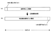
続いて、極性処理手段80が、ブロック内の各サンプルの正負極性処理を行う。上記予測誤差変換手段70により各サンプルの値は、振幅値から予測誤差に置き換えられたが、各サンプルのビット形式は、当初のままである。通常、コンピュータ等の計算機で演算される場合は、各データは32ビット単位で処理され、2の補数表現を用いて表現されている。これを、正負の符号付き絶対値表現に変換し、なおかつ、その絶対値部分を上位に1ビット移動させ、正負の符号ビットをLSB(最下位ビット)に移動させる。極性処理手段80によるビット構成の変換の様子を模式的に示すと図23のようになる。図23(a)は処理前のビット構成であり、図23(b)は処理後のビット構成である。このように正負の符号ビットをLSBに移動させるのは、後の可変長符号化手段90の処理で、各サンプルのビット長を検出し易くするためである。
Subsequently, the polarity processing means 80 performs positive / negative polarity processing of each sample in the block. The value of each sample is replaced with the prediction error from the amplitude value by the prediction error conversion means 70, but the bit format of each sample remains the same. Normally, when being calculated by a computer such as a computer, each data is processed in units of 32 bits and expressed using a two's complement expression. This is converted into a positive / negative signed absolute value expression, and the absolute value portion is moved one bit higher, and the positive / negative sign bit is moved to LSB (least significant bit). FIG. 23 schematically shows how the
次に、可変長符号化手段90が、各サンプルを可変長に変換する処理を行っていく。本実施形態における可変長符号化は、一般にゴロム符号化と呼ばれる方式を採用している。具体的には、1サンプルを構成するビット成分を上位ビット成分と下位ビット成分に分け、下位ビット成分は変更を加えずそのままとし、上位ビット成分は、上位ビットだけを十進数変換した数値分のビット「0」を並べ、最後にセパレータビット「1」を加えた配列とする。例えば、8ビットのビット成分「00101000」を考えてみる。このとき、下位ビット成分を4ビットとすると、下位ビット成分は「1000」となる。上位ビットは「0010」であるため、これを十進数変換した「2」個分の「0」を配列して最後に「1」を加えた「001」に変換される。この結果、8ビットのビット列「00101000」は、7ビットのビット列「0011000」に変換されることになる。本実施形態では、変換の前後でビット成分を不変とする下位ビット成分のビット長を各サンプルで可変とするようにしている。 Next, the variable length coding means 90 performs processing for converting each sample into a variable length. The variable length coding in this embodiment employs a method generally called Golomb coding. Specifically, the bit component constituting one sample is divided into an upper bit component and a lower bit component, the lower bit component is left unchanged, and the upper bit component is a numerical value obtained by decimal conversion of only the upper bit. It is an array in which bit “0” is arranged and separator bit “1” is added at the end. For example, consider an 8-bit bit component “00101000”. At this time, if the lower bit component is 4 bits, the lower bit component is “1000”. Since the upper bits are “0010”, “2” pieces of “0” obtained by decimal conversion are arranged and converted to “001” by adding “1” at the end. As a result, the 8-bit bit string “00101000” is converted into a 7-bit bit string “0011000”. In this embodiment, the bit length of the lower-order bit component that makes the bit component unchanged before and after conversion is made variable for each sample.
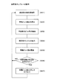
以下、可変長符号化手段90が行う処理を具体的に説明していく。図24は可変長符号化の概要を示すフローチャートである。まず、過去のサンプルのビット長の移動平均である平均ビット長Bfを算出する(ステップS21)。平均ビット長Bfは、過去のビット長の累積値である累積ビット長RBを、過去のサンプル数を基にしたカウンタC3で除算することにより求められる。すなわち、Bf=RB/C3で算出される。累積ビット長RBは、初期状態では0であるので、t=1のサンプルを処理する場合には、t=1のサンプルのビット長Bd(t)を初期値として設定しておく。また、初期のカウンタC3=1と設定する。
Hereinafter, the process performed by the variable-
続いて、時刻tにおけるサンプルのビット長Bd(t)を算出する(ステップS22)。t=2以降のサンプルについては、平均ビット長Bfの算出後、サンプルのビット長Bd(t)を算出する。このビット長Bd(t)は、上記極性処理手段80によりビット構成の変換を行ったことにより算出し易くなっている。図23(b)に示したようなビット構成に変換したことにより、各サンプルのビット構成において先頭にビット「1」が出現したところからがビット長となる。次に、変更部のビット長Bvを算出する(ステップS23)。これは、上記サンプルのビット長Bd(t)から平均ビット長Bfを減じることにより算出される。続いて、データの符号出力を行う(ステップS24)。具体的には、上位Bvビットを十進数変換した数値分だけ「0」を出力した後、セパレータビット「1」を出力し、下位Bfビットを不変部として出力する。符号出力は、ハードディスク、CD−R等の外部記憶装置への記録として行われることになる。次に、累積ビット長RBにビット長Bd(t)を加算する(ステップS25)。同時に、各サンプルの処理を行う度に、カウンタC3を1つずつ加算していく処理を行う。続いて、カウンタC3が所定の数を超えたかどうかを判定する(ステップS26)。所定の数としては、ここでも100程度を設定している。そのため、カウンタ4が100を超えたかどうかを判断することになる。この結果、カウンタが100を超えていたら、累積ビット長RBを半分にする(ステップS27)。具体的には、累積ビット長となる変数RBを2で除算する。同時に、カウンタC3を1/2にする。上記のようにして、各サンプルについて可変ビット長での符号化が行われて行く。
Subsequently, the bit length Bd (t) of the sample at time t is calculated (step S22). For samples after t = 2, after calculating the average bit length Bf, the bit length Bd (t) of the sample is calculated. This bit length Bd (t) is easily calculated by converting the bit configuration by the polarity processing means 80. As a result of the conversion to the bit configuration as shown in FIG. 23B, the bit length starts from the point where the bit “1” appears at the head in the bit configuration of each sample. Next, the bit length Bv of the changing unit is calculated (step S23). This is calculated by subtracting the average bit length Bf from the bit length Bd (t) of the sample. Subsequently, the data code is output (step S24). Specifically, “0” is output for the numerical value obtained by decimal conversion of the upper Bv bits, then the separator bit “1” is output, and the lower Bf bits are output as the unchanged part. The code output is performed as recording to an external storage device such as a hard disk or a CD-R. Next, the bit length Bd (t) is added to the cumulative bit length RB (step S25). At the same time, each time processing of each sample is performed, a process of incrementing the counter C3 one by one is performed. Subsequently, it is determined whether or not the counter C3 exceeds a predetermined number (step S26). Here, about 100 is set as the predetermined number. Therefore, it is determined whether or not the
続いて、符号出力手段100が、可変長符号化手段90から出力された各ブロックの可変長符号化データを、分割されたブロック形態を維持しながら、上記各手段により得られた各データと共に、1つの符号化ファイルに順次収録していく。 Subsequently, the code output means 100, while maintaining the divided block form of the variable length encoded data of each block output from the variable length encoding means 90, together with each data obtained by the above means, Record sequentially in one encoded file.
(1.3符号化データの構造)
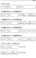
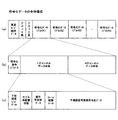
以上のようにして得られた符号化データは、コンピュータに接続されたハードディスク等の記憶装置等に随時記憶され、その後、必要な記憶媒体に対応するフォーマットで記憶される。ここで、最終的に得られた符号化データの全体構成の概略を図23に示す。図25(a)は全体の概略構成、図25(b)はブロック単位の符号化データの概略構成、図25(c)は各ブロックにおけるチャンネル単位の符号化データの概略構成となっている。図25(a)に示すように、全体の符号化データとしては、高速モード識別データ、ブロック数、ブロック長、各ブロック単位の符号化データが記録されている。高速モード識別データとは、高速モードか通常モードかを示す1ビットのデータであり、高速モードである場合は、ブロック分割を行わずに、単一サンプルごとにワークメモリを用いずに符号化処理を行う。本発明による処理は、通常モードである場合に行われる。ブロック数は、符号化データの全ブロック数を示す2バイトのデータである。ブロック長は、1ブロック内のサンプル数を示す4バイトのデータである。符号化データ1〜nは各ブロックの符号化データである。
(1.3 Structure of encoded data)
The encoded data obtained as described above is stored as needed in a storage device such as a hard disk connected to the computer, and then stored in a format corresponding to a necessary storage medium. Here, FIG. 23 shows an outline of the overall configuration of the finally obtained encoded data. FIG. 25A shows the overall schematic configuration, FIG. 25B shows the schematic configuration of the encoded data in units of blocks, and FIG. 25C shows the schematic configuration of the encoded data in units of channels in each block. As shown in FIG. 25A, high-speed mode identification data, the number of blocks, block length, and encoded data for each block are recorded as the entire encoded data. The high-speed mode identification data is 1-bit data indicating whether the mode is the high-speed mode or the normal mode. In the high-speed mode, encoding processing is performed without using a work memory for each single sample without performing block division. I do. The processing according to the present invention is performed in the normal mode. The number of blocks is 2-byte data indicating the total number of blocks of encoded data. The block length is 4-byte data indicating the number of samples in one block. The encoded
図25(b)に示すように、各ブロックの符号化データとしては、符号化条件パラメータ、各チャンネルデータが記録されている。符号化条件パラメータは、各ブロックごとの符号化条件パラメータを記録した最大73ビットのデータである。符号化条件パラメータとしては、下位固定ビット削除手段20による下位固定ビットの削除・分離を行ったか、行った場合は削除・分離のどちらを行ったか、サンプル列再配置手段40によるサンプル列の再配置を行ったかどうか、信号平坦部処理手段50による処理を行ったか、相関フレーム検出手段60による処理を行ったか、予測誤差変換手段70における線形係数の更新間隔はどの程度か等がある。各チャンネルデータは、各チャンネルごとの符号化データであり、本実施形態のように、ステレオ音響信号を符号化した場合は、図25(b)に示すように、2チャンネル分記録される。
As shown in FIG. 25B, encoding condition parameters and channel data are recorded as encoded data of each block. The encoding condition parameter is data of 73 bits at maximum in which the encoding condition parameter for each block is recorded. As the encoding condition parameter, whether the lower fixed bits have been deleted / separated by the lower fixed
図25(c)に示すように、各チャンネルの符号化データとしては、下位固定ビットデータ、サンプル再配置状態、信号平坦部データ、フレーム相関データ、予測誤差可変長符号化データが記録されている。下位固定ビットデータは、下位固定ビット削除手段20により削除せずに分離した場合に記録されるものである。サンプル再配置状態は、図16(b)〜図16(e)に示した4つの状態のうちいずれの状態であるかを示す2ビットのデータである。信号平坦部データは、信号平坦部処理手段50により得られた図17(c)に示すようなデータである。フレーム相関データは、相関フレーム検出手段60により得られた図19(e)に示すようなデータである。予測誤差可変長符号化データは、可変長符号化手段90により得られた可変長の符号化データである。以上のような符号化処理により、符号化条件パラメータを所定の区間ごとに変更可能であると共に、大容量のデータであっても符号化することが可能となる。
As shown in FIG. 25 (c), as the encoded data of each channel, lower fixed bit data, sample rearrangement state, signal flat portion data, frame correlation data, and prediction error variable length encoded data are recorded. . The lower fixed bit data is recorded when separated without being deleted by the lower fixed
(2.本再生装置利用のための音響信号の加工)
上記のようにして得られた符号化データを、本発明に係る音響信号の再生装置で再生することになる。本発明に係る音響信号の再生装置では、上記符号化装置により符号化された音響信号を複数合成して再生する。この合成をスムーズに行うためには、合成対象とする符号化データの各再生時間が同一となるように加工する必要がある。これは、1つの符号化データを基準として、他の符号化データのサンプル数を、基準とした符号化データに合うように補間するようにして増加させることにより行う。また、本実施形態では、再生する利用者が、自由に音楽の構成を変化させることが可能なように、各符号化データをメロディ、コード、リズム等のパートに分けて作成している。各符号化データは、それぞれ図11に示した構造となる。
なお、この再生装置は、端末装置105、107により実現される。
(2. Processing of acoustic signals for using this playback device)
The encoded data obtained as described above is reproduced by the acoustic signal reproducing apparatus according to the present invention. In the acoustic signal reproducing apparatus according to the present invention, a plurality of acoustic signals encoded by the encoding apparatus are synthesized and reproduced. In order to perform the synthesis smoothly, it is necessary to process the reproduction times of the encoded data to be synthesized to be the same. This is performed by increasing the number of samples of other encoded data by interpolating so as to match the encoded data based on the reference with one encoded data as a reference. Further, in this embodiment, each encoded data is created by dividing it into parts such as melody, chord, rhythm, etc. so that the user who reproduces can freely change the composition of music. Each encoded data has the structure shown in FIG.
This playback device is realized by the
(3.音響信号の再生)
以下、本発明に係る音響信号の再生装置について説明する。
(3.1再生装置の構成)
図26は、本発明に係る音響信号の再生装置の一実施形態を示す構成図である。図26において、1は圧縮ブロック読込手段、2はブロック復号手段、3は合成比率設定手段、4は波形合成処理手段、5は合成ブロック蓄積手段、6はサウンドデバイスドライバ、7はサウンドデバイス、8はタイマーである。
(3. Reproduction of acoustic signal)
Hereinafter, a sound signal reproduction apparatus according to the present invention will be described.
(3.1 Configuration of playback device)
FIG. 26 is a block diagram showing an embodiment of a sound signal reproducing apparatus according to the present invention. 26, 1 is a compressed block reading means, 2 is a block decoding means, 3 is a synthesis ratio setting means, 4 is a waveform synthesis processing means, 5 is a synthesis block storage means, 6 is a sound device driver, 7 is a sound device, 8 Is a timer.
圧縮ブロック読込手段1は、圧縮された符号化データファイルから、圧縮ブロック単位でデータの読み込みを行う機能を有している。ブロック復号手段2は、読み込んだ圧縮ブロックを復号して、圧縮符号化前の状態である非圧縮ブロックに復元する機能を有している。合成比率設定手段3は、複数の非圧縮ブロックをどの程度の比率で合成するかを設定する機能を有している。波形合成処理手段4は、ブロック復号手段2で復号された複数の非圧縮ブロック、いわゆるデジタルの波形データを合成比率設定手段3で設定された合成比率で合成する機能を有している。合成ブロック蓄積手段5は、合成された合成ブロックを蓄積するバッファメモリを複数有しており、これらのバッファメモリに蓄積された合成ブロックを、FIFO(ファーストイン・ファーストアウト)方式、すなわち、先に入ってきた情報が、先に出ていく方式で処理する機能を有している。すなわち、合成ブロック蓄積手段5は、波形合成処理手段4から投入された合成ブロックを投入された順序で蓄積し、その順序でサウンドデバイスドライバ6に渡す機能を有することとなる。サウンドデバイスドライバ6は、サウンドデバイス7を駆動させて合成ブロックを音響再生する機能を有しており、サウンドデバイス7は、デジタルデータである合成ブロックをD/A変換して音声として再生する機能を有している。すなわち、サウンドデバイスドライバ6およびサウンドデバイス7は合成ブロック再生手段として機能することになる。タイマー8は、サウンドデバイスによる音響信号の再生と、外部機器の音響信号の再生とのタイミングをとるために利用するタイマーであり、コンピュータにおいて時刻管理を行うタイマーと共用されている。
The compressed
(2.2再生装置の処理動作)
続いて、図26に示した再生装置の処理動作について説明する。まず、再生装置の利用者は、合成比率設定手段3により複数の符号化データの合成比率を設定する。具体的には、再生装置に接続された表示装置に、図5に示すような設定画面を表示させ、この設定画面上で利用者に設定させることになる。図5においては、5トラックが選択できるようになっており、トラック名の右側には音量指定部157、マトリクス159が設けられている。図5の例では、5トラック全てにチェックが付いた状態を示しており、これにより5トラック分の符号化データを読み込み、合成することになる。また、図5の例では、音量指定が5トラック全て最大値「100」となっており、5つの符号化データが同比率で合成されることになる。マトリクス159は、復号・合成して再生する音響信号が圧縮された符号化データファイルの入力を指定する。利用者は、図5に示すようなプレーヤ画面151において、使用するトラック、トラック別の音量、再生ファイル名(符号化データファイル名)を設定する。設定されたトラック別の音量は、各トラックとして設定された符号化データの合成比率として合成比率設定手段3から波形合成処理手段4に与えられることになる。また、マトリクス159で設定された再生ファイル名に対応する符号化データが圧縮ブロック読込手段1により読み込まれることになる。
(2.2 Processing operation of playback device)
Next, the processing operation of the playback device shown in FIG. 26 will be described. First, the user of the playback device sets a combination ratio of a plurality of encoded data by the combination ratio setting means 3. Specifically, a setting screen as shown in FIG. 5 is displayed on the display device connected to the playback device, and the user is allowed to set on the setting screen. In FIG. 5, five tracks can be selected, and a
符号化データである圧縮サウンドデータは図25に示したような構造となっており、ブロック単位で記録されているため、まず、圧縮ブロック読込手段1が符号化データをブロック単位で読み込む。 The compressed sound data, which is encoded data, has a structure as shown in FIG. 25 and is recorded in units of blocks. Therefore, first, the compressed block reading means 1 reads the encoded data in units of blocks.
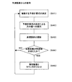
続いて、ブロック復号手段2が読み込んだ符号化データをブロック単位で復号する。復号処理は、基本的には上記符号化装置で行った処理の逆の処理を行うことにより実現される。ここで、復号処理の特徴的な部分について以下に説明する。まず、ブロック復号手段2は、読み込んだビット列のどの部分が変更部であるか、およびどの部分が不変部であるかを判断して、固定ビット長のサンプルを復元する。 Subsequently, the encoded data read by the block decoding means 2 is decoded in units of blocks. The decoding process is basically realized by performing the reverse process of the process performed by the encoding apparatus. Here, the characteristic part of the decoding process will be described below. First, the block decoding means 2 determines which part of the read bit string is a change part and which part is an invariant part, and restores a fixed bit length sample.
ここで、固定ビット長サンプル復元処理の概要を図27のフローチャートに示す。まず、入力された符号データのビット列から変更部に相当するビット列を抽出し、固定長に復号する(ステップS31)。入力されたビット列は、先頭から0が続き、1が出現する。これは、上記符号化のときに、そのような規則で可変長符号化したためである。そのため、ブロック復号手段2は「1」が出現したときのビット列を、符号化時と逆の規則で復号する。例えば「0011000…」というビット列が来た場合に、最初に「1」が出現した「001」までを変更部と判断し、「0」が2個続いているので、「2」の二進数表現「0010」(4ビットの場合)に復号する。 Here, an outline of the fixed bit length sample restoration processing is shown in the flowchart of FIG. First, a bit string corresponding to the changing unit is extracted from the bit string of the input code data, and is decoded to a fixed length (step S31). The input bit string is followed by 0 from the beginning and 1 appears. This is because variable length coding was performed according to such a rule at the time of the above coding. Therefore, the block decoding means 2 decodes the bit string when “1” appears according to a rule reverse to that at the time of encoding. For example, when a bit string “0011000...” Comes, it is determined that the first “1” appears up to “001” as a change part, and two “0” s continue. Decode into “0010” (in case of 4 bits).
次に、過去のサンプルのビット長の移動平均である平均ビット長Bfを算出する(ステップS32)。これは、上記可変長符号化のステップS21の処理と全く同じ処理である。続いて、不変部のビット列を抽出する(ステップS33)。これは、算出された平均ビット長Bf分のビット列を抽出することにより行う。例えば、上記のような「0011000…」というビット列で、「001」までが変更部であったとし、Bf=4であったとすると、続く「1000」が不変部として抽出される。 Next, an average bit length Bf, which is a moving average of the bit lengths of past samples, is calculated (step S32). This is exactly the same process as the variable length encoding step S21. Subsequently, the bit string of the invariant part is extracted (step S33). This is performed by extracting a bit string corresponding to the calculated average bit length Bf. For example, in the bit string “0011000...” As described above, assuming that up to “001” is the changed part and Bf = 4, the subsequent “1000” is extracted as the invariant part.
続いて、ステップS31で復号された変更部のビット列とステップS33で抽出された不変部のビット列を連結して固定長のサンプルを出力する(ステップS34)。固定長に復元されたサンプルは、別途極性復元処理が行われる。次に、累積ビット長RBにビット長Bd(t)を加算する(ステップS35)。同時に、各サンプルの処理を行う度に、カウンタCを1つづつ加算していく処理を行う。続いて、カウンタCが所定の数を超えたかどうかを判定する(ステップS36)。所定の数としては、ここでも100程度を設定している。そのため、カウンタが100を超えたかどうかを判断することになる。この結果、カウンタが100を超えていたら、累積ビット長RBを半分にする(ステップS37)。具体的には、累積ビット長となる変数RBを2で除算する。同時に、カウンタCを1/2にする。ステップS35〜ステップS37の処理は、上記符号化装置の可変長符号化手段90によるステップS25〜ステップS27の処理と全く同じである。 Subsequently, the bit string of the changing part decoded in step S31 and the bit string of the invariant part extracted in step S33 are connected to output a fixed-length sample (step S34). The sample restored to the fixed length is separately subjected to polarity restoration processing. Next, the bit length Bd (t) is added to the cumulative bit length RB (step S35). At the same time, each time the processing of each sample is performed, a process of incrementing the counter C one by one is performed. Subsequently, it is determined whether or not the counter C has exceeded a predetermined number (step S36). Here, about 100 is set as the predetermined number. Therefore, it is determined whether or not the counter exceeds 100. As a result, if the counter exceeds 100, the cumulative bit length RB is halved (step S37). Specifically, the variable RB that is the cumulative bit length is divided by two. At the same time, the counter C is halved. The processing from step S35 to step S37 is exactly the same as the processing from step S25 to step S27 by the variable length encoding means 90 of the encoding device.
上記処理により固定長のサンプルが出力されたら、次に、ブロック復号手段2が、各誤差サンプルの正負極性を復元する。これは、上記符号化装置の極性処理手段80が行った処理の逆を行うことになる。具体的には、正負の符号ビットをMSB(最下位ビット)に移動させ、絶対値部分を下位に1ビット移動させた後、正負の符号付き絶対値で表現されているサンプル値を2の補数を用いた表現に変換する。ビット構成の変換の様子を模式的に示すと図23(b)に示したビット構成から図23(a)に示したビット構成に変換することになる。この処理によりコンピュータによる算術演算を行い易いビット構成となる。 If fixed-length samples are output by the above processing, the block decoding means 2 then restores the positive / negative polarity of each error sample. This is the reverse of the processing performed by the polarity processing means 80 of the encoding device. Specifically, the sign bit of positive / negative is moved to the MSB (least significant bit), the absolute value part is moved down by 1 bit, and then the sample value expressed by the positive / negative signed absolute value is replaced with 2's complement. Convert to an expression using. When the state of bit configuration conversion is schematically shown, the bit configuration shown in FIG. 23B is converted to the bit configuration shown in FIG. This processing makes it easy to perform a bit arithmetic operation by a computer.
また、ブロック復号手段2は、予測誤差値が記録されている誤差サンプルの値を過去のサンプル値に依存しない独立した値に復元する。この独立したサンプルへの復元処理の概要を図28のフローチャートに示す。まず、あらかじめ準備された複数の予測計算式のうち、どの予測計算式を適用するかを決定する(ステップS41)。予測計算式は、符号化時に利用された上記〔数式1〕〜〔数式10〕のいずれかを用いることになる。〔数式1〕〜〔数式11〕のいずれを選択するかについては、各予測式に対応した累積誤差値に基づいて行う。累積誤差A1〜A10は、符号化時に用いたものと同じであり、初期状態では全て0となる。
Further, the
上記〔数式1〕〜〔数式11〕において、e0(t)〜e10(t)は各予測計算式による時刻tのサンプルにおける予測誤差であり、x(t)〜x(t−5)は時刻t〜t−5におけるサンプル値である。 In the above [Equation 1] to [Equation 11], e0 (t) to e10 (t) are prediction errors in the sample at time t according to each prediction calculation formula, and x (t) to x (t-5) are times. It is a sample value in t-t-5.
上述のように、上記〔数式3〕における「a21・x(t−1)+a22・x(t−2)」、上記〔数式4〕における「a31・x(t−1)+a32・x(t−2)+a33・x(t−3)」、上記〔数式5〕における「a41・x(t−1)+a42・x(t−2)+a43・x(t−3)+a44・x(t−4)」、上記〔数式6〕における「a51・x(t−1)+a52・x(t−2)+a53・x(t−3)+a54・x(t−4)+a55・x(t−5)」、上記〔数式8〕における「b21・x(t−1)+b22・x(t−2)」、上記〔数式9〕における「b31・x(t−1)+b32・x(t−2)+b33・x(t−3)」、上記〔数式10〕における「b41・x(t−1)+b42・x(t−2)+b43・x(t−3)+b44・x(t−4)」、上記〔数式11〕における「b51・x(t−1)+b52・x(t−2)+b53・x(t−3)+b54・x(t−4)+b55・x(t−5)」は過去の2〜5個のサンプルに基づく線形予測成分である。この線形予測成分、および、直前のサンプルにおいて算出された予測誤差「e1(t−1)/2」〜「e10(t−1)/2」(誤差フィードバック成分)を用いて時刻tにおけるサンプルe(t)の値を、上記ステップS41で決定したいずれかの予測式にe1(t)〜e10(t)のいずれかとして代入し、x(t)を算出する(ステップS42)。
As described above, “a 21 · x (t−1) + a 22 × x (t−2)” in [Expression 3] and “a 31 · x (t−1) + a 32 in [Expression 4] above. X (t−2) + a 33 · x (t−3) ”,“ a 41 · x (t−1) + a 42 · x (t−2) + a 43 · x (t−) in the above [Formula 5] 3) + a 44 · x (t−4) ”,“ a 51 · x (t−1) + a 52 · x (t−2) + a 53 · x (t−3) + a 54 · x (t−4) + a 55 · x (t−5) ”,“ b 21 · x (t−1) + b 22 · x (t−2) ”in [Expression 8], and in [Expression 9] above. “B 31 · x (t−1) + b 32 · x (t−2) + b 33 · x (t−3)”, “b 41 · x (t−1) + b 42 · x” in [Expression 10] above (T- ) + B 43 · x (t -3) +
続いて、累積誤差A1〜A10に各予測誤差e1(t)〜e10(t)の絶対値を加算する(ステップS43)。具体的には、符号化装置においても用いた上記〔数式13〕に示したように、累積誤差値となる変数A1〜A10を更新していく。同時に、各サンプルの処理を行う度に、カウンタを1つづつ加算していく処理を行う。 Subsequently, the absolute values of the prediction errors e1 (t) to e10 (t) are added to the accumulated errors A1 to A10 (step S43). Specifically, as shown in the above [Equation 13] used in the encoding apparatus, the variables A1 to A10 that are accumulated error values are updated. At the same time, each time the processing of each sample is performed, a process of incrementing the counter one by one is performed.
続いて、カウンタが所定回数を超えたかどうかの判定を行う(ステップS44)。本実施形態では、この所定回数を100回として設定している。すなわち、カウンタが100を超えたかどうかの判定を行う。 Subsequently, it is determined whether the counter has exceeded a predetermined number of times (step S44). In this embodiment, this predetermined number is set as 100 times. That is, it is determined whether or not the counter exceeds 100.
この結果、カウンタが100を超えていたら、累積誤差を半分にする(ステップS45)。具体的には、符号化装置においても用いた上記〔数式14〕に示したように、累積誤差となる変数A1〜A10を2で除算する。同時に、カウンタを0にリセットする。すなわち、ここでのA1〜A10は純粋な意味での累積誤差ではなく、累積誤差の移動平均となっている。本実施形態では、直前の最大100サンプルまでは累積されるが、それ以前のものは半分になるように処理する。これにより、時間的に離れたサンプルの影響が小さくなるようにしている。 As a result, if the counter exceeds 100, the accumulated error is halved (step S45). Specifically, as shown in the above [Equation 14] used in the encoding apparatus, the variables A1 to A10 that are accumulated errors are divided by two. At the same time, the counter is reset to zero. That is, A1 to A10 here are not cumulative errors in a pure sense, but are moving averages of cumulative errors. In the present embodiment, the maximum 100 samples immediately before are accumulated, but the previous ones are processed in half. Thereby, the influence of the sample separated in time is made small.
上記ステップS41〜ステップS45の処理を読み込んだ全誤差サンプルに対して実行することにより、全サンプルの値が元の予測誤差e(t)から振幅値x(t)に復元されることになる。 By executing the processes in steps S41 to S45 on all the error samples that have been read, the values of all the samples are restored from the original prediction error e (t) to the amplitude value x (t).
上記のように、符号化装置において行われた符号化処理に対応した復号処理を行って行くことにより、原デジタル音響信号のサンプルが各ブロック単位で復元され、非圧縮ブロックが得られる。ただし、本発明に係る再生装置では、上記復号処理を、読み込まれた各符号化データに対して並行に行うことになる。この結果、同時に複数の非圧縮ブロックが得られることになる。 As described above, by performing a decoding process corresponding to the encoding process performed in the encoding apparatus, the samples of the original digital sound signal are restored in units of blocks, and an uncompressed block is obtained. However, in the reproduction apparatus according to the present invention, the above decoding process is performed in parallel on each read encoded data. As a result, a plurality of uncompressed blocks are obtained at the same time.
続いて、得られた複数の非圧縮ブロックを、波形合成処理手段4が合成して合成ブロックを生成する。具体的には、各非圧縮ブロックを構成する各サンプルに合成比率を乗じたものを加算することにより行われる。この結果、合成ブロックが得られることになる。 Subsequently, the plurality of uncompressed blocks obtained are synthesized by the waveform synthesis processing means 4 to generate a synthesized block. Specifically, it is performed by adding each sample constituting each non-compressed block multiplied by the synthesis ratio. As a result, a composite block is obtained.
波形合成処理手段4により合成されて得られた合成ブロックは、合成ブロック蓄積手段5に蓄積されていく。本実施形態では、合成ブロック蓄積手段に4ブロックまで蓄積可能となっているため、4ブロック蓄積されるまでは、サウンドデバイスドライバ6による処理は開始されない。図29に示すように、合成ブロック蓄積手段5に合成ブロックが4ブロック蓄積されると、サウンドデバイスドライバ6が、合成ブロック蓄積手段5に蓄積された合成ブロックのうち先頭のブロックを音響再生する。具体的には、サウンドデバイス7が合成ブロックのデータをD/A変換してスピーカに出力することになる。音響再生された合成ブロックは、合成ブロック蓄積手段5から削除される。
The synthesized block obtained by synthesizing by the waveform
合成ブロックが削除されて、合成ブロック蓄積手段5内に余裕ができると、波形合成処理手段4により合成された合成ブロックが合成ブロック蓄積手段5に投入される。これにより、合成ブロック蓄積手段5内は再び最大容量まで蓄積されることになる。波形合成処理手段4により合成された合成ブロックは、現実には、CPUが合成ブロック投入手段として機能することにより、合成ブロック蓄積手段5内に投入される。この合成ブロック投入手段は、合成ブロックを合成ブロック蓄積手段5に単純に投入するだけでなく、合成ブロック蓄積手段5に空きが無い場合は、圧縮ブロック読込手段1、ブロック復号手段2、波形合成処理手段4に対して処理を中断するメッセージを送り、合成ブロック蓄積手段5への合成ブロックの投入を制御している。
When the synthesized block is deleted and there is room in the synthesized
一方、サウンドデバイスドライバ6は、合成ブロック蓄積手段5に蓄積された合成ブロックのうち先頭のブロックを順次音響再生していく。この際、サウンドデバイスドライバ6は、1つの合成ブロックの音響再生を終了する度に、合成ブロック投入手段、圧縮ブロック読込手段1、ブロック復号手段2に対して各処理の実行を許可するメッセージを送る。
On the other hand, the
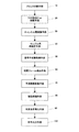
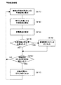
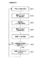
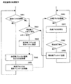
ここで、上記再生装置における処理の概要を整理して図30のフローチャートに示す。まず、合成ブロック投入手段が、合成ブロック蓄積手段5内に空いているバッファメモリが存在するかどうかを探索する(ステップS51)。空いているバッファメモリが存在しない場合は、圧縮ブロック読込手段1およびブロック復号手段2、波形合成処理手段4に対して処理を中断するメッセージを送り、サウンドデバイスドライバ6からの再生終了メッセージの受信待ちとする(ステップS52)。サウンドデバイスドライバ6からの再生終了メッセージがあった場合には、再生が終了した合成ブロックを格納していたバッファメモリから削除する(ステップS53)。サウンドデバイスドライバ6からの再生終了メッセージは、同時に合成ブロック投入手段、圧縮ブロック読込手段1、ブロック復号手段2、波形合成処理手段4にも送信されるため、圧縮ブロック読込手段1、ブロック復号手段2、波形合成処理手段4が処理を再開し、非圧縮ブロックの復号および非圧縮ブロックの合成が行われる(ステップS54)。続いて、空いているバッファメモリに合成ブロックが格納される(ステップS55)。一方、サウンドデバイスでは、常に、合成ブロック蓄積手段5内のバッファメモリを探索しており(ステップS56)、合成ブロックが存在する場合には、合成ブロックを再生する(ステップS57)。1つの合成ブロックの再生を待ち(ステップS58)、再生が終了したら、再生終了メッセージを合成ブロック投入手段、圧縮ブロック読込手段1、ブロック復号手段2、波形合成処理手段4に送信する(ステップS59)。
Here, the outline of the processing in the playback apparatus is organized and shown in the flowchart of FIG. First, the synthesis block input unit searches for a vacant buffer memory in the synthesis block storage unit 5 (step S51). If there is no free buffer memory, a message for interrupting the processing is sent to the compressed block reading means 1, the block decoding means 2, and the waveform synthesis processing means 4, and the reception of the reproduction end message from the
1………ネットワーク
3………ウェブサーバ
5、7………端末装置
1 ...
Claims (7)
前記サーバが、
符号化により圧縮された音響信号で構成される複数の音楽素材より、再生すべき音楽素材を複数個選択する情報を有するオブジェクトタグを生成する生成手段と、
前記オブジェクトタグを、HTML文書の所定の位置に書き込む手段と、
を具備し、
前記端末装置が、
前記HTML文書にアクセスすると、前記オブジェクトタグの記述に従い、選択された複数個の音楽素材に対応する圧縮された音響信号の各々に対して、圧縮ブロックを読み込み、圧縮ブロックを復号化し、復号化された複数の非圧縮ブロックを波形合成して再生する手段と、
を具備することを特徴とする音響信号の再生装置。 In a system in which a server and a terminal device are connected via a network,
The server is
Generating means for generating an object tag having information for selecting a plurality of music materials to be reproduced from a plurality of music materials composed of sound signals compressed by encoding ;
Means for writing the object tag in a predetermined position of the HTML document;
Comprising
The terminal device is
When accessing the HTML document, in accordance with the description of the object tag, for each of the compressed audio signals corresponding to the plurality of selected music materials , the compressed block is read, and the compressed block is decoded and decoded. and means for reproducing a plurality of uncompressed blocks and waveform synthesis was,
An acoustic signal reproducing apparatus comprising:
前記生成手段は、設定されたマトリクスに応じて、再生すべき音楽素材を選択する情報を有するオブジェクトタグを生成することを特徴とする請求項1記載の音響信号の再生装置。 Further comprising means for setting a matrix;
Said generating means in response to a matrix that is set, the reproducing apparatus of the audio signal according to claim 1, wherein the generating the object tags having information for selecting music material to be reproduced.
A program causing a computer to function as the terminal device according to claim 1 .
Priority Applications (1)
| Application Number | Priority Date | Filing Date | Title |
|---|---|---|---|
| JP2004053714A JP4736331B2 (en) | 2004-02-27 | 2004-02-27 | Acoustic signal playback device |
Applications Claiming Priority (1)
| Application Number | Priority Date | Filing Date | Title |
|---|---|---|---|
| JP2004053714A JP4736331B2 (en) | 2004-02-27 | 2004-02-27 | Acoustic signal playback device |
Publications (2)
| Publication Number | Publication Date |
|---|---|
| JP2005242126A JP2005242126A (en) | 2005-09-08 |
| JP4736331B2 true JP4736331B2 (en) | 2011-07-27 |
Family
ID=35023906
Family Applications (1)
| Application Number | Title | Priority Date | Filing Date |
|---|---|---|---|
| JP2004053714A Expired - Fee Related JP4736331B2 (en) | 2004-02-27 | 2004-02-27 | Acoustic signal playback device |
Country Status (1)
| Country | Link |
|---|---|
| JP (1) | JP4736331B2 (en) |
Families Citing this family (4)
| Publication number | Priority date | Publication date | Assignee | Title |
|---|---|---|---|---|
| EP2083584B1 (en) | 2008-01-23 | 2010-09-15 | LG Electronics Inc. | A method and an apparatus for processing an audio signal |
| US8615316B2 (en) | 2008-01-23 | 2013-12-24 | Lg Electronics Inc. | Method and an apparatus for processing an audio signal |
| KR100998913B1 (en) * | 2008-01-23 | 2010-12-08 | 엘지전자 주식회사 | A method and an apparatus for processing an audio signal |
| JP7234935B2 (en) * | 2017-11-24 | 2023-03-08 | ソニーグループ株式会社 | Information processing device, information processing method and program |
Family Cites Families (6)
| Publication number | Priority date | Publication date | Assignee | Title |
|---|---|---|---|---|
| JP3172036B2 (en) * | 1994-03-03 | 2001-06-04 | ローランド株式会社 | Composition device |
| JP3758450B2 (en) * | 2000-01-10 | 2006-03-22 | ヤマハ株式会社 | Server device, client device, and recording medium for creating song data |
| JP2001282259A (en) * | 2000-03-29 | 2001-10-12 | Casio Comput Co Ltd | Music data delivery system, speech data delivery system, data processor and recording medium |
| JP2002091473A (en) * | 2000-06-30 | 2002-03-27 | Fujitsu Ltd | Information processor |
| JP4796670B2 (en) * | 2001-05-18 | 2011-10-19 | 富士通株式会社 | Information providing program, information providing method, and recording medium |
| JP3873781B2 (en) * | 2002-03-06 | 2007-01-24 | ヤマハ株式会社 | Automatic pitch correction device and program applied to the device |
-
2004
- 2004-02-27 JP JP2004053714A patent/JP4736331B2/en not_active Expired - Fee Related
Also Published As
| Publication number | Publication date |
|---|---|
| JP2005242126A (en) | 2005-09-08 |
Similar Documents
| Publication | Publication Date | Title |
|---|---|---|
| JP4952469B2 (en) | Information processing apparatus, information processing method, and program | |
| US7507894B2 (en) | Sound data encoding apparatus and sound data decoding apparatus | |
| JP2009157272A (en) | Audio playback device | |
| US7840290B2 (en) | Encoded digital audio reproducing apparatus | |
| JP4736331B2 (en) | Acoustic signal playback device | |
| JP2787018B2 (en) | Audio data recording method and audio data recording device | |
| JP4973422B2 (en) | Signal recording / reproducing apparatus and method | |
| JP4256332B2 (en) | Audio data encoding apparatus and audio data decoding apparatus | |
| JP4170795B2 (en) | Time-series signal encoding apparatus and recording medium | |
| JP4357852B2 (en) | Time series signal compression analyzer and converter | |
| EP1793381A1 (en) | Musical composition reproducing device, musical composition reproducing method and so forth | |
| JP4249540B2 (en) | Time-series signal encoding apparatus and recording medium | |
| JP4139704B2 (en) | Time series signal encoding apparatus and decoding apparatus | |
| JP4229092B2 (en) | Recording apparatus and method, reproducing apparatus and method | |
| JP2005038541A (en) | Device and method for recording/reproducing contents data | |
| JP2005166216A (en) | Reproducing apparatus of sound signal | |
| JP2004198559A (en) | Encoding method and decoding method for time-series signal | |
| JP2005215162A (en) | Reproducing device of acoustic signal | |
| JP4184817B2 (en) | Time series signal encoding method and apparatus | |
| JP2003015692A (en) | Audio signal recording device, audio signal reproducing device and computer readable storage medium | |
| JP4139697B2 (en) | Time series signal encoding method and apparatus | |
| JP3889738B2 (en) | Inverse quantization apparatus, audio decoding apparatus, image decoding apparatus, inverse quantization method, and inverse quantization program | |
| JP2009122609A (en) | Acoustic signal coder and acoustic signal decoder, their method, program and recording medium | |
| JP2002100120A (en) | Intermusic control method of music data, information processor and intermusic control program of music data | |
| JP4319895B2 (en) | Time series signal encoding device |
Legal Events
| Date | Code | Title | Description |
|---|---|---|---|
| A621 | Written request for application examination |
Free format text: JAPANESE INTERMEDIATE CODE: A621 Effective date: 20070223 |
|
| A977 | Report on retrieval |
Free format text: JAPANESE INTERMEDIATE CODE: A971007 Effective date: 20100215 |
|
| A131 | Notification of reasons for refusal |
Free format text: JAPANESE INTERMEDIATE CODE: A131 Effective date: 20100223 |
|
| A521 | Request for written amendment filed |
Free format text: JAPANESE INTERMEDIATE CODE: A523 Effective date: 20100426 |
|
| A01 | Written decision to grant a patent or to grant a registration (utility model) |
Free format text: JAPANESE INTERMEDIATE CODE: A01 Effective date: 20110405 |
|
| A61 | First payment of annual fees (during grant procedure) |
Free format text: JAPANESE INTERMEDIATE CODE: A61 Effective date: 20110418 |
|
| R150 | Certificate of patent or registration of utility model |
Free format text: JAPANESE INTERMEDIATE CODE: R150 |
|
| FPAY | Renewal fee payment (event date is renewal date of database) |
Free format text: PAYMENT UNTIL: 20140513 Year of fee payment: 3 |
|
| LAPS | Cancellation because of no payment of annual fees |