JP4734207B2 - Imaging device - Google Patents
Imaging device Download PDFInfo
- Publication number
- JP4734207B2 JP4734207B2 JP2006261739A JP2006261739A JP4734207B2 JP 4734207 B2 JP4734207 B2 JP 4734207B2 JP 2006261739 A JP2006261739 A JP 2006261739A JP 2006261739 A JP2006261739 A JP 2006261739A JP 4734207 B2 JP4734207 B2 JP 4734207B2
- Authority
- JP
- Japan
- Prior art keywords
- image
- frame
- display
- zoom
- shooting
- Prior art date
- Legal status (The legal status is an assumption and is not a legal conclusion. Google has not performed a legal analysis and makes no representation as to the accuracy of the status listed.)
- Expired - Fee Related
Links
Images


Description
この発明は撮影画像などを表示する表示手段を有するデジタルカメラ、デジタルビデオカメラなどの撮像装置、特に、周辺の背景を省略して画面中央の枠内の領域で撮影する撮像装置に関する。 The present invention relates to an imaging apparatus such as a digital camera or a digital video camera having display means for displaying a captured image, and more particularly to an imaging apparatus that captures an image in an area within a frame at the center of a screen while omitting a peripheral background.
近年、デジタルカメラ、デジタルビデオカメラなどの撮像装置のデジタル化が進み、撮影画像を画像処理してデジタル的に記録し再生する技術が飛躍的に進歩している。ここで、撮影画像の全体を記録するだけでなく、撮影画像の所定部分を切り取った記録もなされている。銀塩カメラにおいては、撮影後に所定の範囲のみをプリントするトリミングが広く知られており、デジタルカメラなどにおいてもデジタル技術を利用してトリミングが行なえる。 2. Description of the Related Art In recent years, digitalization of imaging devices such as digital cameras and digital video cameras has progressed, and technology for processing captured images digitally and recording and reproducing them has dramatically improved. Here, not only the entire photographed image is recorded, but also a recorded part of the photographed image is cut out. In a silver salt camera, trimming for printing only a predetermined range after photographing is widely known, and in a digital camera or the like, trimming can be performed using digital technology.
最近のインターネットの普及に伴なって、好みの撮影画像をホームページ(HP)やブログ(WEBLOG)などにアップロードして公開する撮影画像の利用方法が増加している。
ホームページやブログなどにアップロードされる撮影画像は、文章をビジュアル的に補足する点を主要な役目としており、文章記載のスペースを損なってはならず、従来の撮影画像とは異なる縦横比や枠形状となっても何ら差し支えない。また、印画紙にプリントする意図がなく、画面の縦横比を考慮する必要もない。そして、ホームページやブログなどの撮影画像では、所定部分の撮影画像が重要であり、撮影画像の周辺部においては、背景など余計なものが撮影されているため、ホームページやブログなどへのアップロードに適さず、背景など余計なものの省略が好まれる。
With the recent spread of the Internet, there are an increasing number of methods for using photographed images to upload and publish favorite photographed images on homepages (HP) or blogs (WEBLOG).
Shooting images uploaded to websites, blogs, etc. have the main role of visually supplementing text, so the space for writing text must not be impaired, and the aspect ratio and frame shape differ from conventional shooting images There is no problem even if it becomes. Also, there is no intention to print on photographic paper, and there is no need to consider the aspect ratio of the screen. And for images taken on websites, blogs, etc., a certain part of the photographed image is important, and in the periphery of the photographed image, extra items such as the background are photographed, making it suitable for uploading to websites, blogs, etc. The omission of unnecessary items such as backgrounds is preferred.
従来においては、デジタル技術を利用するトリミングは撮影後のパソコンなどにおける処理とされ、デジタルカメラは、ホームページやブログなどへの撮影画像のアップロードに考慮して設計されていない。そのため、たとえば、デジタルカメラなどで撮影した画像をパソコン(PC)に入力(転送)し、PC上で撮影画像から所定部分を切り取ってホームページやブログなどへのアップロードがなされている。 Conventionally, trimming using a digital technique is a process in a personal computer or the like after photographing, and a digital camera is not designed in consideration of uploading a photographed image to a homepage or a blog. Therefore, for example, an image taken with a digital camera or the like is input (transferred) to a personal computer (PC), and a predetermined portion is cut out from the taken image on the PC and uploaded to a homepage or a blog.
デジタルカメラからパソコンなどの外部装置に撮影画像を転送するために、たとえば、特開2003−174610号公報では、外部装置に撮影画像を転送する転送ボタンをデジタルカメラに設け、デジタルカメラをパソコンに接続する通信手段を自動的に判別して、判別した通信手段に対応した最適の画像データを転送するように構成されている。この構成によれば、判別した通信手段の転送方式に対応した画像データを自動的に転送でき、転送方式の指定操作や転送する画像データの対応付け操作が省略できる。
デジタルカメラで撮影されてパソコンに入力された撮影画像から所定部分を切り取ってホームページやブログなどへのアップロードを行なうためには、専用のソフトウエアが必要となる。また、撮影後の処理であるため、パソコンにおけるトリミングの時点で撮影画像の欠点に気付いてもやり直しができず、満足できる画像を得ることが難しい。
上記特開2003−174610号公報では、通信手段の転送方式に対応した画像データをパソコンに自動的に転送しているにすぎず、ホームページやブログなどへのアップロードに適する画像を撮影する構成となっていない。
In order to cut out a predetermined portion from a photographed image taken with a digital camera and input to a personal computer and upload it to a home page or a blog, dedicated software is required. In addition, since the process is after shooting, it is difficult to obtain a satisfactory image because it cannot be redone even if a defect in the shot image is noticed at the time of trimming on a personal computer.
In the above Japanese Patent Laid-Open No. 2003-174610, only image data corresponding to the transfer method of the communication means is automatically transferred to a personal computer, and an image suitable for uploading to a homepage, a blog, or the like is taken. Not.
また、デジタルカメラの小型化の推進に伴ない、レンズの収差、特に歪曲収差が画像の周辺部に発生し、画像が歪みやすい。被写体が、風景や人物などでなく、レコードジャケット、書籍、ちらし、パンフレット、メニュー、ハンカチやアクセサリーなどの日常小物、フィギュアなどのような厚みのない平板状のものであれば、歪みの目立つ撮影画像となり、ホームページやブログなどへのアップロードに適さない。そして、歪みのある撮影画像の修正は、画像サイズの変更、色補正、輝度補正などと比較してはるかに難しい。 In addition, along with the promotion of downsizing of digital cameras, lens aberrations, particularly distortion, occur in the peripheral part of the image, and the image is easily distorted. If the subject is not a landscape or a person, but a record jacket, book, flyer, pamphlet, menu, everyday accessory such as a handkerchief or accessory, or a flat plate with no thickness, such as a figure, a photographed image with noticeable distortion It is not suitable for uploading to homepages and blogs. Further, it is much more difficult to correct a distorted captured image as compared with image size change, color correction, brightness correction, and the like.
レンズ収差などによる画像の歪みは、ズームレンズにおいても生じ、ズームレンズでは焦点距離の変化にともなって歪曲収差も変化する。そのため、風景や人物の撮影に支障がないように、ズームレンズは広角域、望遠域で歪曲収差の正負のバランスを取って設計されている。しかし、ズームレンズのすべての焦点距離において、レコードジャケットなどの厚みのない平板状のものに適した歪曲収差に設計すれば、光学系全体が大きくなリ、小型軽量化が難しくなるとともに、高価なものとなり、好ましくない。 Image distortion due to lens aberration or the like also occurs in the zoom lens. In the zoom lens, the distortion aberration also changes as the focal length changes. For this reason, the zoom lens is designed with a positive and negative balance of distortion aberration in the wide-angle range and the telephoto range so as not to hinder the shooting of landscapes and people. However, if all the focal lengths of the zoom lens are designed with distortion aberration suitable for a flat plate with no thickness such as a record jacket, the entire optical system becomes large, and it is difficult to reduce the size and weight, and it is expensive. This is undesirable.
本発明は、デジタル技術ならではの画像切り出し機能によってホームページやブログなどへのアップロードに適した画像を撮影できる撮像装置の提供を目的としている。 An object of the present invention is to provide an imaging apparatus capable of capturing an image suitable for uploading to a homepage, a blog, or the like by an image cutout function unique to digital technology.
請求項1記載の本発明によれば、撮像装置は、被写体を照射するLED光源と、
被写体を撮影する撮影レンズと、上記撮影レンズを介して得られた上記被写体の像信号を撮像する撮像手段と、上記撮像手段によって得られた画像を表示する画像表示手段と、上記撮像手段によって得られた像信号の画像のうち、上記LED光源によって照射された被写体のうち照射の効果がない部分を除く像信号の画像、または、上記撮影レンズ周辺部による性能の落ちた部分を除く像信号の画像を囲む枠を上記撮像手段によって得られた像信号の画像に合成して上記画像表示手段に表示する表示制御手段とを有して構成されている。
According to the first aspect of the present invention, the imaging apparatus includes: an LED light source that irradiates a subject;
Obtained by a photographing lens for photographing a subject, an imaging means for capturing an image signal of the subject obtained through the photographing lens, an image display means for displaying an image obtained by the imaging means, and the imaging means Of the image signal obtained, the image signal image excluding the portion of the subject irradiated by the LED light source that does not have the effect of irradiation, or the image signal excluding the portion where the performance is deteriorated by the periphery of the photographing lens And a display control unit configured to synthesize a frame surrounding the image with the image of the image signal obtained by the imaging unit and display the image on the image display unit .
請求項2記載の本発明によれば、撮像装置は、被写体を撮影する撮影レンズと、上記撮影レンズを介して得られた上記被写体の像信号を撮像する撮像手段と、上記撮像手段によって得られた像信号を表示する画像表示手段と、上記撮像手段によって得られた像信号のうち、上記撮影レンズの周辺部を介して得られる像信号を囲む枠を上記撮像手段によって得られた像信号に合成して上記画像表示手段に表示する表示制御手段とを有して構成されている。
According to the second aspect of the present invention, an imaging apparatus is obtained by a photographing lens that photographs a subject, an imaging unit that captures an image signal of the subject obtained through the photographing lens, and the imaging unit. image display means for displaying an image signal, among the image signals obtained by the imaging means, a frame surrounding an image signal obtained through the peripheral portion of the photographing lens on the image signal obtained by said image pickup means synthesized and is constituted by a display control means for displaying on said image display means.
請求項3記載の本発明によれば、撮像装置は、被写体を撮影する撮影レンズと、上記撮影レンズを介して得られた上記被写体の像信号を撮像する撮像手段と、撮像手段によって得られた像信号を表示する画像表示手段と、上記撮像手段によって得られた像信号と、上記撮影レンズの周辺部を介して得られる像信号を囲む枠内の像信号とを上記画像表示手段に併せてマルチ表示する表示制御手段とを有して構成されている。
According to the present invention described in claim 3, the imaging device, obtained a photographic lens for photographing an object Utsushitai, imaging means for imaging an image signal of the subject obtained through the photographing lens, by the imaging means An image display means for displaying the image signal obtained, an image signal obtained by the imaging means, and an image signal in a frame surrounding the image signal obtained via the peripheral portion of the photographing lens are displayed on the image display means. In addition, it has a display control means for performing multi-display .
請求項4記載の本発明によれば、撮像装置は被写体を照射するLED光源をさらに有し、LED光源によって枠内の像信号に対応する被写体部分を照射している。
請求項5記載の本発明によれば、上記撮影レンズの周辺部を介して得られる像信号が、上記撮像レンズの収差、上記撮影レンズの周辺光量落ち、LED光源からの照射の不均一性のいずれかの影響を受けたものとなっている。
請求項6記載の本発明によれば、撮像装置は像信号が画像処理されて記録される記録手段をさらに有し、枠内における上記撮像素子の隣接した画素どうしを加算して得た像信号が上記記録手段に記録されている。
According to a fourth aspect of the present invention, the imaging apparatus further includes an LED light source that irradiates a subject, and the subject portion corresponding to the image signal in the frame is irradiated by the LED light source.
According to the fifth aspect of the present invention, the image signal obtained through the peripheral portion of the photographing lens has an aberration of the imaging lens, a decrease in the peripheral light amount of the photographing lens, and nonuniformity of irradiation from the LED light source. It has been affected by either.
According to the sixth aspect of the present invention, the imaging apparatus further includes recording means for recording the image signal after image processing, and the image signal obtained by adding the adjacent pixels of the imaging element in the frame. Is recorded in the recording means.
請求項1記載の本発明では、画像表示手段の画面内に枠を合成して表示しており、この枠内の画像を撮影すれば、背景など余計なものを含まず、明るさが略均一で歪みのない撮影画像が得られる。
In the first aspect of the present invention, a frame is synthesized and displayed in the screen of the image display means, and if an image in the frame is captured , the background is not included and the brightness is substantially uniform. A captured image without distortion can be obtained.
請求項2記載の本発明では、画像表示手段の画面内に枠を合成して表示しており、この枠内の画像を撮影すれば、背景など余計なものを含まず、歪みのない撮影画像が得られる。
According to the second aspect of the present invention, a frame is synthesized and displayed in the screen of the image display means, and if an image within this frame is captured, the captured image does not include any extraneous items such as the background and has no distortion. Is obtained.
請求項3記載の本発明では、撮影しようとしている画像と枠との関係を容易に確認、判断でき、枠内の画像を撮影すれば、背景など余計なものを含まず、歪みのない撮影画像が得られる。
According to the third aspect of the present invention, the relationship between the image to be photographed and the frame can be easily confirmed and judged, and if the image within the frame is photographed, the captured image does not include any extraneous objects such as the background and has no distortion. Is obtained.
請求項4記載の本発明では、LED光源を点灯することによって撮影結果を事前に予測できるとともに、明るさの略同一の中央部のみを撮影できる。また、被写体の一部が反射で光る現象を防止しながら撮影が行える。
請求項5記載の本発明では、枠はトリミング枠として機能し、枠内の画像を撮影することにより、撮影後のトリミングが不要となる。
請求項6記載の本発明では、隣接した画素どうしを加算しているため、画素数が減少して処理が迅速に行え、感度のよい画像が得られる。また、同色の画素信号を加算すれば、S/N比を改善できる。
In the present invention according to claim 4 , the photographing result can be predicted in advance by turning on the LED light source, and only the central portion having substantially the same brightness can be photographed. In addition, it is possible to take a picture while preventing a phenomenon that a part of the subject shines by reflection.
In the present invention described in claim 5 , the frame functions as a trimming frame, and by capturing an image within the frame, trimming after shooting is unnecessary.
In the present invention described in
本発明では、画面表示手段の画面内に、中央部の領域を囲んでズームレンズの焦点距離に応じて大きさの変化する枠を合成して表示し、この枠内の画像を撮影、記録している。 In the present invention, in the screen of the screen display means, a frame that surrounds the central region and changes in size according to the focal length of the zoom lens is displayed, and an image in this frame is captured and recorded. ing.
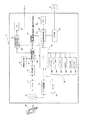
以下、図面を参照しながら本発明の一実施例を詳細に説明する。図1は、デジタルカメラとして具体化された撮像装置の主要部の概略ブロック図を示す。
図1に示すように、デジタルカメラ(撮像装置)10は、ズームレンズ12、ズーム制御回路14、撮像手段16、AFE回路(アナログフロントエンド回路)18、画像処理回路20、画像判定回路22、圧縮回路24、記録制御回路26、記録手段(メモリ)28、出力手段29、表示制御回路30、表示手段32、中央制御回路34、一連のスイッチ群36、ストロボ(ストロボ手段)38などを備えて構成されている。
Hereinafter, an embodiment of the present invention will be described in detail with reference to the drawings. FIG. 1 is a schematic block diagram of a main part of an imaging apparatus embodied as a digital camera.
As shown in FIG. 1, a digital camera (imaging device) 10 includes a
たとえば、撮像手段16はCCD、CMOSセンサなどの撮像素子から、画像表示手段としての表示手段32は液晶ディスプレイ(LCD)、有機ELディスプレイなどから、中央制御回路34はCPU、MPUなどからそれぞれ形成される。また、一連のスイッチ群36は、パワースイッチ(パワーSW)36a、レリーズスイッチ(レリーズSW)36b、メニューキー36c、決定キー(OKキー)36d、ズームスイッチ(ズームSW)36e、モードキー36fなどからなる。メニューキー36cは、たとえば十字キーとされ、左右上下の選択キーを兼ね、メニューキーで選択された設定は決定キー(OKキー)36dによって決定される。スイッチ36c〜36fなどのスイッチ操作によって、撮影・再生のモード切替えや撮影モードの切替えなども行なわれる。
For example, the image pickup means 16 is formed from an image pickup device such as a CCD or CMOS sensor, the display means 32 as an image display means is formed from a liquid crystal display (LCD), an organic EL display, or the like, and the
ズームレンズ12はズーム制御回路14の制御のもとで所定のズーム位置に変更され、被写体40からの像はズームレンズを介してCCDなどの撮像手段16上に結像されて光電変換され、AD変換回路を含むAFE回路18でデジタル化される。デジタル化された画像信号は、画像処理回路20に入力され、画像処理回路では、画像信号の色、階調、シャープネスなどを補正処理し、撮影時には後段の回路で圧縮処理がなされる。
The
AFE回路18は、撮像手段(CCD)16からのアナログ信号をデジタル化するだけでなく、CCDの出力する信号を取捨選択する機能を持ち、CCDの受光面の一部からの限定された画像データを抽出する。この限定された所定の範囲から抽出された画像データを記録すれば、トリミングと同じ効果が得られる。CCD16の受光面に撮像されるすべてを記録したくない場合に、トリミングされた画像(トリミング画像)を撮影する工夫は非常に有効となる。
The
多く画素からなるCCD16においては、同色の画素信号を加算することにより、S/N比を改善でき、この加算処理もAFE回路18で行なわれる。加算処理すると、有効利用される画素数が少なくなる。しかし、一般的に、パソコン(PC)のモニタなどでは、モニタの能力に制約があり、必要以上の画素数はなんら意味をなさない。そのため、たとえば、デジタルカメラ10の撮影画像をホームページやブログなどに利用する場合には、画像サイズはプリントを前提とするものより小さくてよく、画素数の減少は問題とならない。また、画素数が多すぎると、処理に時間を要し、不利となる。
In the
画像処理回路20は、リサイズ回路20aを有し、CCD16からの画像信号は、撮影に先立って撮影の構図やタイミングを確認して液晶ディスプレイ(LCD)などの表示手段32に表示されるサイズにリサイズ手段で加工され、表示制御回路(表示制御手段)30で制御されてLCD32にスルー動画像(ライブビュー画像)としてリアルタイムに表示される。
また、表示制御回路30は、枠表示回路30aを有し、枠表示回路は、所定の領域の画像のみを利用するための枠(トリミング枠)をLCD32にスーパーインポーズ式に表示(マルチ表示)する。後述のように、この枠は、画面の歪みを考慮して画面の中央部の領域を示すものとなる。なお、この枠の形状をユーザーが調整可能にするとよい。
The
The
ユーザーはLCD32に表示された画像(スルー動画像、ライブビュー画像)を見ながら、枠(トリミング枠)を参考にして撮影時に構図やタイミングを決めて撮影の操作を行なう。液晶ディスプレイ32の表示は高精細な表示でないため、トリミング時に枠内の所定領域を拡大しても表示画像は粗くならない。そのため、画像を拡大表示してもよい。
While viewing the images (through moving images and live view images) displayed on the
撮影前のスルー動画像だけでなく、LCD32には、メモリ28に記録された画像信号も画像処理回路20で伸長されて再生・表示される。また、メニューキー30cなどによるカメラ操作あるいはカメラの各種機能やモード設定も、LCD32に表示される。
In addition to the through moving image before photographing, on the
画像判定回路22は、画像処理回路20の信号を利用して、CCD16から入力された画像データの特徴などを判定する。
The
圧縮回路24は、JPEGコア部など静止画用圧縮部24aと、MPEG4、H.264などの圧縮コア部からなる動画用圧縮部24bとを有して構成され、画像処理回路20から出力された信号は、圧縮回路で圧縮処理されて、記録制御回路26を介して記録手段(メモリ)28に記録される。
The
メモリ28に記録された画像データは、出力手段29を介してパソコンなどの外部装置42に転送されて、ホームページやブログなどにアップロードされる。本発明においては、ホームページやブログへのアップロードを前提にした画像データは、撮影時からアップロードに対応した撮影方法を行なって、アップロード時に所定の効果が得られるような工夫がなされる。また、画像判定回路22の出力から、ストロボ38や後述するLED(発光ダイオード)光源などの補助光発光手段の補助的な光を照射すべきか否かを判定して対応する制御がなされる。
The image data recorded in the
ズーム制御回路14、AFE回路18、画像処理回路20、画像判定回路22、圧縮回路24、記録制御回路26、表示制御回路30などの構成部材は中央制御回路(CPU)34で集中的に制御される。たとえば、CPU34は、LCD32の表示とスイッチ36a〜36fの入力状況とからユーザーの操作を判定し、その判定結果からデジタルカメラ10のシーケンスを制御する。メニューキー36c、決定キー36d、モードキー36fなどの対応するスイッチの操作をCPU34が検出、実行することにより、本発明の特徴であるトリミング画像を作成する撮影モード(ブログモード)に切り替えられる。また、CPU34は、ズーム制御回路14を介してズームレンズ12の焦点距離を切り替えてズーミング位置をモニタする。
Components such as the
ズーム撮影においては、ズーム制御用のボタンを設け、ズームレンズ12をズーム制御回路14で制御してズームレンズによる被写体の拡大(光学ズーム)ができなければ、CCD16から撮像画像を取り出す領域をCPU34が限定する制御をAFE回路18で実行し、取り出された部分画像を全画像として表示、記録してズームの延長とするデジタルズームが一般的に採用されている。また、ストロボ38を状況に応じて発光し、被写体に補助光を照射して明るさの不足や不均一な明るさを防止して撮影がなされる。
In zoom shooting, if a zoom control button is provided and the
図2(A)〜(F)は、画像情報を液晶ディスプレイ(LCD)に表示してなされる撮影シミュレーションの模式図を示し、図3(A)(B)は、パソコンに転送された撮影画像を示す。
図2を参照しながら、机41上に置かれたレコードジャケットを被写体40として撮影する状況を説明する。たとえば、カメラの撮影範囲32aとレコードジャケット(被写体)40との間での垂直、水平の関係が正しく設定されないと、パソコンに転送されたとき、図3(A)のように、傾斜した画像40がパソコンのモニタ42aに表示される。
FIGS. 2A to 2F are schematic diagrams of a shooting simulation performed by displaying image information on a liquid crystal display (LCD), and FIGS. 3A and 3B are shot images transferred to a personal computer. Indicates.
A situation in which a record jacket placed on the
図3(A)に示すような傾斜した画像40が撮影されると、ホームページやブログにアップロードしたとき、同時に表示される文章との関係が美しくないとともに、バランスも悪くなり、文章を書くスペースが少なくなる。そのため、ユーザーは、図2(B)に矢視で示すように、撮影範囲32aの上方にレコードジャケット40を移動して、撮影範囲の上縁とレコードの上縁とを合わせようとする。しかし、通常、レンズの周辺部は中央部(光軸付近)より収差等の影響で性能が落ち、周辺部に歪みが発生するため、レンズの周辺部にあるレコードジャケット40の上端40aが歪んで変形した画像となる。
When a tilted
もし、図2(A)の傾斜した画面か、図2(B)の歪んだ画面かいずれかしか選択の余地がなければ、ユーザーはストレスを感じることとなる。
そのため、実施例では、図2(C)のように、画面中心近くの収差の影響を受けない場所に、傾きを生じないような枠(トリミング枠)32bを設定し、この枠内の限定された画像のみを取り出し可能としている。画面内のレンズの収差の影響を受けない範囲で枠32bを可変とすることにより、レコードジャケット(被写体)40の置かれた机41まで撮影する必要がなくなり、メモリが節約され、後工程でのトリミング工程が省略される。枠32bを利用すれば、図3(B)に示すように、正しい関係のレコードジャケット40の画像がパソコンのモニタ42aに表示される。
If there is only room for selection of either the slanted screen of FIG. 2A or the distorted screen of FIG. 2B, the user will feel stress.
Therefore, in the embodiment, as shown in FIG. 2C, a frame (trimming frame) 32b that does not cause an inclination is set at a location that is not affected by the aberration near the center of the screen, and is limited within this frame. It is possible to extract only the images that have been recorded. By making the
枠32b内の撮影部分は、図2(D)に示すように、被写体としてのレコードジャケット40がレンズ収差の一番少ない状態でLCD32の画面中央に表示される。しかし、図2(E)のようにLCDの表示範囲の全域に拡大表示してもよいし、図2(F)のように、CCD16によるモニタ範囲32cと枠32b内の画像の両方をLCD32にマルチ表示してもよい。
図2(E)の拡大表示においては、画面全域で大きく表示されるため、焦点が正しく合っているか、明るさが均一か、全体に色むらがないかなどが容易に確認できる。
また、図2(F)のマルチ表示においては、デジタルカメラ10が撮影しようとしているものと枠32bとの関係を容易に確認、判断できる。また、可変の枠32bを切り替えながら行なう撮影での切り替え状態が分かりやすく、マルチ表示の撮影モードであることもすぐ理解できる。
As shown in FIG. 2D, the photographing part in the
In the enlarged display of FIG. 2 (E), since it is displayed large over the entire screen, it can be easily confirmed whether the focus is correct, the brightness is uniform, or there is no color unevenness on the whole.
In the multi-display in FIG. 2F, the relationship between what the
CPU34は、ズーム制御回路14を介してズームレンズ12の焦点距離を切り替えてズーミング位置をモニタしている。レンズの収差の影響は、ズームレンズ12のズーム位置によって変化するから、収差の一番少ない焦点距離位置の枠範囲とズーム位置との関係をフラッシュROM(図示しない)に予め記憶し、CPU34はフラッシュROMを読み出しながら、ズーミング位置に従って枠表示回路30aを制御する。また、枠32bの範囲、大きさをいくつかのパターンからユーザーが選択できるようにしてもよいし、連続的に可変にしてもよい。この場合には、枠32bを選択する専用スイッチや、枠を可変とする専用スイッチを設けてもよいし、他の機能のスイッチ、たとえば、メニューキー36c、決定キー36dを利用して枠を選択可能、または可変としてもよい。
The
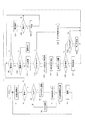
図4は、上記のような構成のデジタルカメラ10の制御シーケンスのフローチャートを示す。
まず、S1でCCD12からの出力信号(画像情報)がLCD32にスルー動画像(ライブビュー画像)としてリアルタイムに表示される。ユーザーはLCD32の表示画像で被写体40を確認し、撮影タイミングや構図を決めて撮影操作がなされる。S2で撮影するか否かが判定され、撮影しなければ、S9に分岐して再生モードであるか否かが判定される。S9で再生モードであれば、S21でLCD32を再生表示に切り替えて、メモリ28内の画像データが再生表示される。
FIG. 4 shows a flowchart of a control sequence of the
First, in S1, an output signal (image information) from the
再生表示された画像データを外部のパソコン42などに転送するか否かがS22で判定され、転送するときは、S23でデータ転送してからS9に戻り、転送しなければS22からS9に戻る。
S9で再生モードが設定されていなければ、電源のOFFがS10で判定され、ここで、電源0FFの操作がなされていれば、電源をOFFとして終了し、電源OFFの操作がなければ、S11でズーム制御がなされる。ズーム制御は、たとえば、ユーザーがズームSW36eを操作してズーム制御回路14の制御のもとでなされる。
In S22, it is determined whether or not to transfer the reproduced and displayed image data to an external
If the playback mode is not set in S9, it is determined in S10 that the power supply is turned off. If the power supply 0FF is operated, the power supply is turned off and the process ends. Zoom control is performed. The zoom control is performed, for example, under the control of the
図2(C)のように撮影範囲を限定する撮影モード(ブログモード)の設定がS12で判定され、ブログモードであれば、表示制御手段としてS13でズームレンズ12のズーム位置に従って、画面周囲に比較して歪曲収差の比較的少ない画面中央領域を囲う枠(トリミング枠)32bがLCD32に被写体像とともに合成(重畳)されて表示される。表示される枠形状は、たとえば、図2(D)〜(F)に示すものとされ、これらの枠形状はユーザーによって切り替えられ(S14)、枠形状の変更に伴なって対応する表示モードに切り替えられる(S15)。なお、図2(D)の枠形状が初期設定される。
As shown in FIG. 2C, the setting of the shooting mode (blog mode) that limits the shooting range is determined in S12, and if it is the blog mode, the display control means moves to the periphery of the screen according to the zoom position of the
拡大表示がS16で判定され、拡大表示の操作があれば、図2(E)のような拡大表示がS17でなされてS1に戻る。拡大表示の操作がなければ、次にS18でマルチ表示の操作がS18で判定され、マルチ表示の操作があれば、図2(F)のようなマルチ表示がS19でなされてS1に戻る。拡大表示、マルチ表示の操作がなければ、初期設定の枠形状のままS1に戻る。
S12でブログモードの撮影をしなければ、S20に分岐してブログ設定を解除してから、S1に戻る。
このように、ブログモードの設定時にはLCD32の表示に工夫が施され、ユーザーは好みの表示を設定できる。
If the enlarged display is determined in S16 and there is an enlarged display operation, the enlarged display as shown in FIG. 2E is made in S17 and the process returns to S1. If there is no enlargement display operation, then in S18, the multi-display operation is determined in S18, and if there is a multi-display operation, the multi-display as shown in FIG. 2F is made in S19 and the process returns to S1. If there is no enlarged display or multi-display operation, the process returns to S1 with the default frame shape.
If shooting in the blog mode is not performed in S12, the process branches to S20 to cancel the blog setting, and then returns to S1.
As described above, when the blog mode is set, the display on the
LCD32の工夫された表示画面を見ながら、S2で撮影がなされ、S3でブログモードでの撮影が判定される。ホームページやブログに掲載されるレコードジャケット、書籍、ハンカチやアクセサリーなどの日常小物、フィギュアなどの厚みのない平板状の被写体40は、ストロボ38の光を反射させてその一部で光る現象が生じやすい。そのため、ブログモードでは、ストロボ38を発光させない発光禁止手段を用いた撮影とし(S4)、S14で設定した枠32bの枠外(周辺部)を使用しないで枠内の撮影情報のみを像信号取出手段としての画像処理回路20によって取り出し(S5)、その結果を圧縮してメモリ28に記録する(S7、S8)。S3でブログモードでなければ、S6に分岐して枠32bを使用しない通常の撮影、たとえばオート撮影がなされ(S6)、撮影された画像データが圧縮、記録される(S7、S8)。
このように、この実施例によれば、ブログモードを選択することにより、好みの枠形状のもとで周辺部(枠外部分)を除いて撮影できるため、背景など余計なものを含まず、歪みの少ない撮影画像が得られる。つまり、ホームページやブログなどのアップロードに適する画像が撮影できる。
While looking at the devised display screen of the
As described above, according to this embodiment, by selecting the blog mode, it is possible to shoot without the peripheral portion (outside frame portion) under the preferred frame shape, so that it does not include extraneous items such as the background, and is distorted. A photographed image with little can be obtained. In other words, images suitable for uploading homepages and blogs can be taken.
図5は、ズームレンズを含む断面で切断した撮像装置としてのデジタルカメラの横断面であり、画角とLED光源の放射範囲との関係図を示し、図6、図7(A)(B)は、本発明の別実施例(実施例2)における机上でのレコードジャケットの撮影シミュレーションの模式図を示す。
ストロボ38のストロボ光は、撮影時に瞬間的に発光するにすぎず、どのような画像が得られるかを判断し難い。そのため、実施例2においては、被写体40に光を投射するLED(発光ダイオード)の光源(LED光源)38’がストロボ38とともにデジタルカメラ10に設けられ、LED光源の下での撮影を可能としている。LED光源38’の光は、ストロボ38のように一瞬光るだけでなく、常時点灯できるため、撮影結果を事前に予測できる。また、被写体40の一部が反射で光る現象を防止しながら撮影を楽しむことができる。
Figure 5 is a cross section of the digital camera as an image pickup device cut along a section including a zoom lens, shows a graph showing the relationship between the radiation range of the angle of view and the LED light source, FIG. 6, FIG. 7 (A) ( B) is a schematic diagram of a recording simulation of a record jacket on a desk in another embodiment (embodiment 2) of the present invention.
The strobe light from the
ストロボ38の強力な発光とは異なり、LED光源38’の光は弱く、集光しないと十分な明るさを得ることができず、その放射範囲は撮影レンズとしてのズームレンズ12の画角閘より狭い範囲となる。しかし、図6のように、レコードジャケット40などの撮影においては、レコードジャケットの背景まで光を届かせる必要はなく、レコードジャケットを含む所定の範囲だけが照射すればよい。つまり、ブログモードであれば、LED光源38’の光でも支障なく、LED光源が有効に利用できる。
Unlike the strong light emission of the
LED光源38’で照射する範囲以外は、表示しても意味はないから、図7(A)のようにレコードジャケット40の周辺部を含めてLCD32に表示する代わりに、図7(B)のように必要な部分である中央部のレコードジャケットのみを表示すればわかりやすくてよい。また、不要部分(周辺部)を削除して必要な部分(中央部)のみを拡大すれば、見やすい表示となる。LED光源38’の照射光は均一にはなり難いとはいえ、略均一な中央部のみを取り出しているため、均一な明るさで撮影できる。微妙な明るさのムラは、画像処理で均一化して補正できる。
Since it is meaningless to display other than the range irradiated by the LED light source 38 ', instead of displaying on the
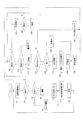
図8は、実施例2におけるデジタルカメラ10の制御シーケンスのフローチャートで示す。S12以下のブログモードにおいて、実施例1と異なることを除けば、実施例2のフローチャートは、実施例1における図4のフローチャートに略等しい。図4のフローチャート(実施例1)と相違する部分について述べると、S12でブログモードと判定されると、S25でCCDの出力から被写体40の明暗が判定される。被写体40が暗ければ、S26で補助光発光手段としてLED光源38’が照射され、照射された部分のみを枠表示し(S27)、LED光源の発光パターンの強度分布を補正する画像処理を行なって(S28)、LCD32に表示する。CCD16の隣接する同色の画素の出力を加算すると、感度が向上して暗いシーンやLED光にも敏感になるので、S29で画素加算をしてからS1に戻って撮影がなされる。
FIG. 8 is a flowchart illustrating a control sequence of the
被写体40との距離によって、モニタ範囲におけるLED光源38’の照射位置が被写体に対し変化するため、合焦結果と連動して表示画面中における枠表示の位置や大きさを変化させるとよい。また、ズーム位置によって、LED光源38’の照射エリアの大きさも変化するため、ズーム位置に対応させて枠表示も変更される。
Since the irradiation position of the
S25で被写体40が暗くない(明るい)と判定されれば、S30に分岐して枠表示のみを行ない、実施例1と同様に収差の影響を受けにくい中央部を範囲指定する。そして、S29で画素を加算し、感度を上昇させてからS1に戻って撮影がなされる。 If it is determined in S25 that the subject 40 is not dark (bright), the process branches to S30 and only the frame display is performed, and the central portion that is not easily affected by the aberration is specified as in the first embodiment. In step S29, the pixels are added to increase the sensitivity, and then the process returns to step S1 to perform shooting.
このように、LED光源38’を補助光とすれば、暗いシーンでも適切な明るさで照明した画像が撮影できる。特に、レコードジャケット、書籍、ハンカチやアクセサリーなどの日常小物、フィギュアなどのような厚みのない平板状のものは、反射などによって雰囲気が変わりやすい。しかし、実施例2のように、LED光源38’を用いて常時照射を可能とすれば、ユーザーはこだわりのアイテム(被写体)の照明状態をLCD32上でリアルタイムに確認しながら撮影でき、十分満足できる画像が得られる。
Thus, if the LED light source 38 'is used as auxiliary light, an image illuminated with appropriate brightness can be taken even in a dark scene. Especially for everyday items such as record jackets, books, handkerchiefs and accessories, and flat plates with no thickness such as figures, the atmosphere tends to change due to reflection. However, if the LED light source 38 'can be used for continuous irradiation as in the second embodiment, the user can take a picture while confirming the illumination state of the particular item (subject) on the
LED38’の照射範囲を広くすると、光の密度が減少して暗くなる。しかし、実施例2のように収差のない範囲に相当する所定の範囲(周辺部を除いた中央部)に限定して照射することにより、周辺部の背景などに無駄な光量をロスすることなく光量を確保でき、歪みのない画面を略均一な照明で撮影できる。
When the irradiation range of the
この考え方を応用すれば、レンズ自身の周辺光量落ちに対策を施したデジタルカメラも考えられる。すなわち、実施例2では、LED光源38’の照射の不均一性に対抗策を講じているが、レンズ自身も光軸から離れると光量が落ち、レコードジャケットなどを撮影するときに、均一な明るさにならずにユーザーが不満を持ちやすい。また、人物を主な被写体とする一般のスナップ撮影では、様々な被写体が画面に入るために不均一な明るさもあまり気にならないのに対して、特定の被写体のみをターゲットにした撮影では、不均一な明るさが気になる。そこで、本発明の考え方を応用し、光量落ちが所定値以下の場所を取り出して枠表示するような考え方も有効となる。
このような考え方を考慮して、図4のフローチャートS13のステップでの制御を行なってもよい。
なお、上記実施例1、2において、ズームレンズを前提として説明したが、単焦点レンズにおいても上記の技術を同様に適用できる。
If this idea is applied, a digital camera that takes measures against a drop in the amount of light around the lens itself can be considered. That is, in the second embodiment, a countermeasure is taken against the non-uniformity of the irradiation of the
In consideration of such a concept, the control in the step of the flowchart S13 in FIG. 4 may be performed.
In the first and second embodiments, the description has been made on the assumption that the zoom lens is used. However, the above technique can be similarly applied to a single focus lens.
図9〜図10を参照しながら、本発明の他の実施例(実施例3)について詳細に説明する。この実施例3では、ズーム位置によって収差の出方が変化することを利用して、歪みの少ない撮影を可能としている。つまり、一般にズームレンズの設計においては、すべての焦点距離領域において収差なし設計にすることは困難で、広角側(W側)、望遠側(T側)の端部では、たる型や糸巻き型の収差が発生し、その中間領域でそれらを相殺する設計としている。
図9(A)(B)(C)は、広角側、焦点距離S(広角側と望遠側との間のある一点)、望遠側での歪みの概念図を示す。図9(A)(C)に示すように、広角側では所定の画像(点線で示す)に対してたる型の歪みが、望遠側では糸巻き型の歪みが生じ、たる型、糸巻き型の歪曲収差を相殺する図9(B)に示す焦点距離Sをズーム距離Sとすれば、レコードジャケットなどを収差なく撮影できる。収差を相殺する焦点距離Sをズーム距離Sとして撮影する場合について以下に述べる。
Another embodiment (Example 3) of the present invention will be described in detail with reference to FIGS. In the third embodiment, it is possible to shoot with less distortion by utilizing the fact that the manner of aberration changes depending on the zoom position. In other words, in general, in designing a zoom lens, it is difficult to design without aberration in all focal length regions. At the end on the wide angle side (W side) and the telephoto side (T side), a barrel type or a pincushion type is used. Aberrations occur and are designed to cancel them in the middle region.
FIGS. 9A, 9B, and 9C are conceptual diagrams of distortion on the wide-angle side, focal length S (one point between the wide-angle side and the telephoto side), and distortion on the telephoto side. As shown in FIGS. 9A and 9C, a barrel distortion occurs with respect to a predetermined image (indicated by a dotted line) on the wide-angle side, and a pincushion distortion occurs on the telephoto side. If the focal length S shown in FIG. 9B for canceling out the aberration is the zoom distance S, a record jacket or the like can be photographed without aberration. A case where photographing is performed with the focal length S that cancels aberration as the zoom distance S will be described below.
図10は、机上でのレコードジャケットの撮影シミュレーションの模式図を示す。図10に示すように、ズーム位置Sを利用して机41上のレコードジャケット20を撮影するとき、レコードジャケットの輪郭を枠(トリミング枠)32aに合わせて撮影すればよい。被写体周囲の背景などを撮影したくなければ、枠32aをマルチ表示(図2(F)参照)して、背景を除いた部分だけを取り出して撮影すればよく、これは、実施例1の考えに等しい。
FIG. 10 shows a schematic diagram of a shooting simulation of a record jacket on a desk. As shown in FIG. 10, when the
図11は実施例3におけるデジタルカメラ10の制御シーケンスのフローチャートを示す。図11のフローチャートは、ブログモード時のモニタ表示部のフローチャート(S31〜S33)、および通常ズーム制御とするためにS36のステップを追加している点で図4のフローチャートと相違し、他のステップは図4のフローチャートに等しい。
すなわち、S12でブログモードが設定されていれば、ズーム制御手段として図9(B)の焦点距離Sに対応する所定のズーム位置にズームレンズ12が自動的に設定され(S31)、枠32aを選択して表示する(S32)。この方法によれば、無駄なトリミング工程が省略できる。また、不要な部分(収差のある周辺部)の記録を避けてメモリに余裕を持たすことができ、多数の画像が記録可能となる。
また、ホームページやブログへの掲載には必要以上の画素数は不要であるため、画素加算(S33)して感度を向上させてからS1に戻って撮影するため、シャッタースピードを上げても手振れのない撮影が可能となる。
FIG. 11 shows a flowchart of a control sequence of the
That is, if the blog mode is set in S12, the
In addition, since the number of pixels more than necessary is not necessary for posting on a homepage or blog, the pixel is added (S33) to improve sensitivity, and then the process returns to S1 to shoot, so even if the shutter speed is increased, camera shake does not occur. No photography is possible.
このように、実施例3では、ホームページやブログでの画面に合わせて縦横が正確にそろった画像が、レンズ歪みのない焦点距離Sで容易に撮影できる。 As described above, in the third embodiment, it is possible to easily shoot an image having an accurate vertical and horizontal alignment in accordance with a screen on a homepage or a blog with a focal length S without lens distortion.
図12(A)(B)(C)はズームレンズの一例における広角端、中間位置、望遠端でのレンズの断面図、図13(A)(B)(C)は図12に示すズームレンズの広角端、中間位置、望遠端における歪曲収差の収差図を示す。
図13(A)(B)(C)に示すように、歪曲収差が・1%以内の焦点距離をズーム距離Sとすれば、収差の目立たない画像が広範囲で撮影できる。
12A, 12B, and 12C are cross-sectional views of the lens at the wide-angle end, the intermediate position, and the telephoto end in an example of the zoom lens, and FIGS. 13A, 13B, and 13C are zoom lenses shown in FIG. FIG. 5A shows aberration diagrams of distortion at the wide-angle end, intermediate position, and telephoto end.
As shown in FIGS. 13A, 13B, and 13C, if the focal length within 1% of the distortion is set as the zoom distance S, an image with no noticeable aberration can be taken in a wide range.
非球面形状は、xを光の進行方向を正とした光軸とし、yを光軸と直交する方向にとると、下記の式にて表される。ただし、rは近軸曲率半径、Kは円錐係数、A4、A6、A8、A10はそれぞれ4次、6次、8次、10次の非球面係数を示す。
x=(y2/r)/[1+{1−(K+1)(y/r)2}1/2]+A4y4+A6y6+A8y8+A10y10
The aspherical shape is expressed by the following equation, where x is an optical axis with the traveling direction of light as positive and y is in a direction orthogonal to the optical axis. Here, r is a paraxial radius of curvature, K is a conical coefficient, and A 4 , A 6 , A 8 and A 10 are 4th, 6th, 8th and 10th order aspherical coefficients, respectively.
x = (y 2 / r) / [1+ {1- (K + 1) (y / r) 2} 1/2] + A 4 y 4 + A 6
ズームレンズ12を構成する各レンズの諸係数は以下とされる。ここで、rはレンズ面の曲率半径、Dはレンズ面間の間隔、ndはレンズのd線の屈折率、νdはレンズのアッベ数、fは全系焦点距離、FNOはFナンバー、である。
面番 r D nd νd
1 -11.535 ASP 0.92 1.52542 55.78
2 44.496 ASP D2
3 5.974 ASP 1.43 1.80610 40.92
4 -9.711 0.01 1.56384 60.67
5 -9.711 0.95 1.51633 64.14
6 -21.069 0.10
7 絞り 0.20
8 14.326 1.13 1.78800 47.37
9 -14.326 0.01 1.56384 60.67
10 -14.326 0.50 1.80518 25.42
11 3.669 D11
12 61.202 2.31 1.52542 55.78
13 -8.645 ASP D13
14 -41.658 ASP 1.00 1.52542 55.78
15 -14.560 0.13
16 ∞ 0.40 1.54771 62.84
17 ∞ 0.20
18 ∞ 0.50 1.51633 64.14
19 ∞ 0.42
Various coefficients of the lenses constituting the
Surface number r D nd νd
1 -11.535 ASP 0.92 1.52542 55.78
2 44.496 ASP D2
3 5.974 ASP 1.43 1.80610 40.92
4 -9.711 0.01 1.56384 60.67
5 -9.711 0.95 1.51633 64.14
6 -21.069 0.10
7 Aperture 0.20
8 14.326 1.13 1.78800 47.37
9 -14.326 0.01 1.56384 60.67
10 -14.326 0.50 1.80518 25.42
11 3.669 D11
12 61.202 2.31 1.52542 55.78
13 -8.645 ASP D13
14 -41.658 ASP 1.00 1.52542 55.78
15 -14.560 0.13
16 ∞ 0.40 1.54771 62.84
17 ∞ 0.20
18 ∞ 0.50 1.51633 64.14
19 ∞ 0.42
非球面係数
面番 r K
1 -11.535 -4.739
A4 A6 A8 A10
-2.42892e-05 5.93100e-06 1.06044e-07 -7.34218e-09
面番 r K
2 44.496 -286.654
A4 A6 A8 A10
4.03482e-04 -9.96697e-06 1.21655e-06 -3.75453e-08
面番 r K
3 5.974 -0.361
A4 A6
-7.83563e-04 -0.353928e-05
面番 r K
13 -8.645 -5.933
A4 A6 A8 A10
-8.36717e-04 -3.42841e-05 2.37781e-06 -4.11212e-08
面番 r K
14 -41.658 -418.964
A4 A6 A8
-2.41451e-03 -1.13925e-05 2.20868e-06
Aspheric coefficient Surface number r K
1 -11.535 -4.739
A 4 A 6 A 8 A 10
-2.42892e-05 5.93100e-06 1.06044e-07 -7.34218e-09
Surface number r K
2 44.496 -286.654
A 4 A 6 A 8 A 10
4.03482e-04 -9.96697e-06 1.21655e-06 -3.75453e-08
Surface number r K
3 5.974 -0.361
A 4 A 6
-7.83563e-04 -0.353928e-05
Surface number r K
13 -8.645 -5.933
A 4 A 6 A 8 A 10
-8.36717e-04 -3.42841e-05 2.37781e-06 -4.11212e-08
Surface number r K
14 -41.658 -418.964
A 4 A 6 A 8
-2.41451e-03 -1.13925e-05 2.20868e-06
ズームデータ
f 6.51 8.32 18.53
FNO 3.17 3.6 5.90
2ω 57.9° 46.8° 22.0°
D2 12.75 9.20 1.50
D11 2.45 4.10 12.37
D13 2.44 2.44 2.68
Zoom data f 6.51 8.32 18.53
F NO 3.17 3.6 5.90
2ω 57.9 ° 46.8 ° 22.0 °
D2 12.75 9.20 1.50
D11 2.45 4.10 12.37
D13 2.44 2.44 2.68
中間焦点距離(中間焦点距離S)では、歪曲収差の小さい焦点距離が設定されており、特に実施例では、一般的な中間焦点距離よりも広角端側に中間焦点距離S(実施例では8.32mm)を設定することにより、レコードジャケットなどの被写体を遠く離れることなく撮影しやすくしている。
なお、一般的な中間焦点距離は慣例的に以下の条件式で示され、実施例では11.00mmとなる。
一般的な中間焦点距離=(広角端焦点距離×望遠端焦点距離)0.5
また、カメラ内の画像処理により歪曲収差を小さくする場合、歪曲収差の大きさを画像処理後の大きさとしてもよい。
In the intermediate focal length (intermediate focal length S), a focal length with a small distortion is set. In particular, in the embodiment, the intermediate focal length S (8. 32mm) makes it easy to photograph a subject such as a record jacket without leaving a distance.
Note that the general intermediate focal length is conventionally expressed by the following conditional expression, which is 11.00 mm in the embodiment.
General intermediate focal length = (wide-angle end focal length x telephoto end focal length) 0.5
When the distortion is reduced by image processing in the camera, the magnitude of the distortion may be the size after image processing.
上述した実施例は、この発明を説明するためのものであり、この発明を何等限定するものでなく、この発明の技術範囲内で変形、改造等の施されたものも全てこの発明に包含されることはいうまでもない。
たとえば、実施例では、デジタルカメラを具体例としてあげているが、本発明の対象となる撮像装置はデジタルカメラに限定されず、たとえば、デジタルビデオカメラはもちろん、デジタルカメラの機能を持つ携帯電話、ノートパソコンなどのカメラ付モバイルツールなども撮像装置に含まれる。
The above-described embodiments are for explaining the present invention, and are not intended to limit the present invention. All modifications, alterations, etc. within the technical scope of the present invention are included in the present invention. Needless to say.
For example, in the embodiments, a digital camera is given as a specific example, but the imaging device that is the subject of the present invention is not limited to a digital camera. For example, a digital video camera as well as a mobile phone having a digital camera function, Mobile devices with cameras such as notebook computers are also included in the imaging device.
上記のように、本発明によれば、デジタル技術ならでは画像切り出し機能によってホームページやブログなどへのアップロードに適した画像を容易に撮影できる。 As described above, according to the present invention, an image suitable for uploading to a homepage, a blog, or the like can be easily taken by an image cutout function unique to digital technology.
本発明は、液晶ディスプレイのような画像表示手段を持つデジタルカメラなどの撮像装置に広範囲に応用できる。 The present invention can be widely applied to an imaging apparatus such as a digital camera having an image display means such as a liquid crystal display.
10 デジタルカメラ(撮像装置)
12 ズームレンズ
14 ズーム制御回路(ズーム制御手段)
16 撮像素子(CCD)
18 AFE回路(アナログフロントエンド回路)
20 画像処理回路(像信号取出手段)
22 画像判定回路
28 記録手段(メモリ)
30 表示制御回路(表示制御手段)
30a 枠表示回路
32 液晶ディスプレイ(LCD;画像表示手段)
32a カメラの撮影範囲
32b 枠(トリミング枠)
34 CPU(中央制御回路)
38 ストロボ(補助光発光手段)
38’ LED光源(補助光発光手段)
40 被写体
41 机
42 パソコン
42a パソコンのモニタ
10 Digital camera (imaging device)
12
16 Image sensor (CCD)
18 AFE circuit (analog front-end circuit)
20 Image processing circuit (image signal extracting means)
22
30 Display control circuit (display control means)
30a
32a
34 CPU (Central Control Circuit)
38 Strobe (auxiliary light emission means)
38 'LED light source (auxiliary light emitting means)
40
Claims (1)
上記ズームレンズを介して得られた上記被写体の像信号を撮像する撮像手段と、
通常の撮影とトリミング画像を作成する撮影モードとに切替可能な切替手段と、
上記ズームレンズの焦点距離を設定するズーム制御手段と、
上記撮像手段により得られた画像を表示画面に表示する表示手段と、
上記表示画面に表示された画像と、上記表示画面の中央部領域を示す枠とを重畳させることが可能な表示制御手段と、
上記切替手段が上記トリミング画像を作成する撮影モードに切替えられると、上記ズーム制御手段が上記ズームレンズの焦点距離を広角端と望遠端の間の中間にある歪曲収差を相殺する焦点距離に設定制御させ、上記表示制御手段によって上記表示画面に上記枠を重畳させ、上記枠内の画像を記録させる中央制御回路と、
を有することを特徴とする撮像装置。 A zoom lens to shoot the subject,
Imaging means for imaging the image signal of the subject obtained through the zoom lens;
A switching means capable of switching between normal shooting and a shooting mode for creating a trimmed image ;
Zoom control means for setting the focal length of the zoom lens;
Display means for displaying an image obtained by the imaging means on a display screen;
An image displayed on Symbol display screen, display control means capable of superimposing the frame indicating the central region of the display screen,
When the switching means is switched to a shooting mode for creating the trimmed image, the zoom control means controls the setting of the focal length of the zoom lens to a focal length that cancels out distortion aberration between the wide-angle end and the telephoto end. A central control circuit that superimposes the frame on the display screen by the display control means and records an image in the frame;
An imaging device comprising:
Priority Applications (1)
| Application Number | Priority Date | Filing Date | Title |
|---|---|---|---|
| JP2006261739A JP4734207B2 (en) | 2006-09-27 | 2006-09-27 | Imaging device |
Applications Claiming Priority (1)
| Application Number | Priority Date | Filing Date | Title |
|---|---|---|---|
| JP2006261739A JP4734207B2 (en) | 2006-09-27 | 2006-09-27 | Imaging device |
Publications (3)
| Publication Number | Publication Date |
|---|---|
| JP2008085524A JP2008085524A (en) | 2008-04-10 |
| JP2008085524A5 JP2008085524A5 (en) | 2009-09-10 |
| JP4734207B2 true JP4734207B2 (en) | 2011-07-27 |
Family
ID=39355945
Family Applications (1)
| Application Number | Title | Priority Date | Filing Date |
|---|---|---|---|
| JP2006261739A Expired - Fee Related JP4734207B2 (en) | 2006-09-27 | 2006-09-27 | Imaging device |
Country Status (1)
| Country | Link |
|---|---|
| JP (1) | JP4734207B2 (en) |
Families Citing this family (2)
| Publication number | Priority date | Publication date | Assignee | Title |
|---|---|---|---|---|
| JP2011199479A (en) * | 2010-03-18 | 2011-10-06 | Toshiba Corp | Device, program, and method for processing information |
| JP2013219544A (en) * | 2012-04-09 | 2013-10-24 | Ricoh Co Ltd | Image processing apparatus, image processing method, and image processing program |
Citations (11)
| Publication number | Priority date | Publication date | Assignee | Title |
|---|---|---|---|---|
| JP2000078445A (en) * | 1998-06-16 | 2000-03-14 | Ricoh Co Ltd | Digital camera |
| JP2003111041A (en) * | 2001-09-28 | 2003-04-11 | Canon Inc | Image processor, image processing system, image processing method, storage medium and program |
| JP2003319351A (en) * | 2002-04-23 | 2003-11-07 | Sony Corp | Service providing system, broadcast apparatus and method, receiving apparatus and method, recording medium, and program |
| JP2004072207A (en) * | 2002-08-02 | 2004-03-04 | Fuji Photo Film Co Ltd | Image signal processing apparatus and electronic camera |
| JP2004072206A (en) * | 2002-08-02 | 2004-03-04 | Fuji Photo Film Co Ltd | Electronic camera |
| JP2004179710A (en) * | 2002-11-25 | 2004-06-24 | Fuji Photo Film Co Ltd | Electronic camera |
| JP2004272578A (en) * | 2003-03-07 | 2004-09-30 | Minolta Co Ltd | Image pickup unit and distortion correction method |
| JP2005115598A (en) * | 2003-10-07 | 2005-04-28 | Konica Minolta Holdings Inc | Image processing method and apparatus |
| JP2006115117A (en) * | 2004-10-13 | 2006-04-27 | Olympus Corp | Imaging apparatus |
| JP2006129101A (en) * | 2004-10-29 | 2006-05-18 | Casio Comput Co Ltd | Method of trimming image, imaging apparatus, image processing unit and program |
| JP2006253939A (en) * | 2005-03-09 | 2006-09-21 | Fuji Photo Film Co Ltd | Imaging apparatus |
-
2006
- 2006-09-27 JP JP2006261739A patent/JP4734207B2/en not_active Expired - Fee Related
Patent Citations (11)
| Publication number | Priority date | Publication date | Assignee | Title |
|---|---|---|---|---|
| JP2000078445A (en) * | 1998-06-16 | 2000-03-14 | Ricoh Co Ltd | Digital camera |
| JP2003111041A (en) * | 2001-09-28 | 2003-04-11 | Canon Inc | Image processor, image processing system, image processing method, storage medium and program |
| JP2003319351A (en) * | 2002-04-23 | 2003-11-07 | Sony Corp | Service providing system, broadcast apparatus and method, receiving apparatus and method, recording medium, and program |
| JP2004072207A (en) * | 2002-08-02 | 2004-03-04 | Fuji Photo Film Co Ltd | Image signal processing apparatus and electronic camera |
| JP2004072206A (en) * | 2002-08-02 | 2004-03-04 | Fuji Photo Film Co Ltd | Electronic camera |
| JP2004179710A (en) * | 2002-11-25 | 2004-06-24 | Fuji Photo Film Co Ltd | Electronic camera |
| JP2004272578A (en) * | 2003-03-07 | 2004-09-30 | Minolta Co Ltd | Image pickup unit and distortion correction method |
| JP2005115598A (en) * | 2003-10-07 | 2005-04-28 | Konica Minolta Holdings Inc | Image processing method and apparatus |
| JP2006115117A (en) * | 2004-10-13 | 2006-04-27 | Olympus Corp | Imaging apparatus |
| JP2006129101A (en) * | 2004-10-29 | 2006-05-18 | Casio Comput Co Ltd | Method of trimming image, imaging apparatus, image processing unit and program |
| JP2006253939A (en) * | 2005-03-09 | 2006-09-21 | Fuji Photo Film Co Ltd | Imaging apparatus |
Also Published As
| Publication number | Publication date |
|---|---|
| JP2008085524A (en) | 2008-04-10 |
Similar Documents
| Publication | Publication Date | Title |
|---|---|---|
| JP4423678B2 (en) | Imaging apparatus, imaging method, and program | |
| JP5706654B2 (en) | Imaging device, image display method and program | |
| KR101700366B1 (en) | Digital photographing apparatus and control method thereof | |
| US8502883B2 (en) | Photographing apparatus and photographing control method | |
| US10477113B2 (en) | Imaging device and control method therefor | |
| JP2008022306A (en) | Imaging device and program thereof | |
| KR101058025B1 (en) | Image display device and method using dual thumbnail mode | |
| US8576306B2 (en) | Image sensing apparatus, image processing apparatus, control method, and computer-readable medium | |
| JP4977569B2 (en) | Imaging control apparatus, imaging control method, imaging control program, and imaging apparatus | |
| JP4734207B2 (en) | Imaging device | |
| US8514305B2 (en) | Imaging apparatus | |
| JP2007049408A (en) | Photographing device | |
| JP5854235B2 (en) | Imaging apparatus, imaging method, and program | |
| JP2007060131A (en) | Camera with live view display function | |
| JP4760496B2 (en) | Image data generation apparatus and image data generation method | |
| JPWO2018193698A1 (en) | Display control device, imaging device, and display control method | |
| JP4760497B2 (en) | Image data generation apparatus and image data generation method | |
| JP4720255B2 (en) | Camera device, photographing method and photographing program | |
| JP4897577B2 (en) | Imaging device | |
| JP2006287517A (en) | Camera apparatus, photographing method, and photographing program | |
| JP5158438B2 (en) | Image generating apparatus, image generating method, and program | |
| JP7394151B2 (en) | Display method | |
| JP2006013677A (en) | Information processing apparatus, imaging apparatus, image file generating method, and image display processing program | |
| JP2008178031A (en) | Imaging apparatus | |
| JP4934983B2 (en) | Camera device, photographing method and photographing program |
Legal Events
| Date | Code | Title | Description |
|---|---|---|---|
| A521 | Request for written amendment filed |
Free format text: JAPANESE INTERMEDIATE CODE: A523 Effective date: 20090723 |
|
| A621 | Written request for application examination |
Free format text: JAPANESE INTERMEDIATE CODE: A621 Effective date: 20090723 |
|
| A977 | Report on retrieval |
Free format text: JAPANESE INTERMEDIATE CODE: A971007 Effective date: 20110128 |
|
| A131 | Notification of reasons for refusal |
Free format text: JAPANESE INTERMEDIATE CODE: A131 Effective date: 20110207 |
|
| A521 | Request for written amendment filed |
Free format text: JAPANESE INTERMEDIATE CODE: A523 Effective date: 20110330 |
|
| TRDD | Decision of grant or rejection written | ||
| A01 | Written decision to grant a patent or to grant a registration (utility model) |
Free format text: JAPANESE INTERMEDIATE CODE: A01 Effective date: 20110418 |
|
| A01 | Written decision to grant a patent or to grant a registration (utility model) |
Free format text: JAPANESE INTERMEDIATE CODE: A01 |
|
| A61 | First payment of annual fees (during grant procedure) |
Free format text: JAPANESE INTERMEDIATE CODE: A61 Effective date: 20110425 |
|
| FPAY | Renewal fee payment (event date is renewal date of database) |
Free format text: PAYMENT UNTIL: 20140428 Year of fee payment: 3 |
|
| R151 | Written notification of patent or utility model registration |
Ref document number: 4734207 Country of ref document: JP Free format text: JAPANESE INTERMEDIATE CODE: R151 |
|
| FPAY | Renewal fee payment (event date is renewal date of database) |
Free format text: PAYMENT UNTIL: 20140428 Year of fee payment: 3 |
|
| S111 | Request for change of ownership or part of ownership |
Free format text: JAPANESE INTERMEDIATE CODE: R313111 |
|
| R350 | Written notification of registration of transfer |
Free format text: JAPANESE INTERMEDIATE CODE: R350 |
|
| S531 | Written request for registration of change of domicile |
Free format text: JAPANESE INTERMEDIATE CODE: R313531 |
|
| R350 | Written notification of registration of transfer |
Free format text: JAPANESE INTERMEDIATE CODE: R350 |
|
| LAPS | Cancellation because of no payment of annual fees |