JP4733296B2 - Link parts for aircraft engine mounting systems - Google Patents
Link parts for aircraft engine mounting systems Download PDFInfo
- Publication number
- JP4733296B2 JP4733296B2 JP2001197581A JP2001197581A JP4733296B2 JP 4733296 B2 JP4733296 B2 JP 4733296B2 JP 2001197581 A JP2001197581 A JP 2001197581A JP 2001197581 A JP2001197581 A JP 2001197581A JP 4733296 B2 JP4733296 B2 JP 4733296B2
- Authority
- JP
- Japan
- Prior art keywords
- engine
- link
- span
- aircraft
- concentrated mass
- Prior art date
- Legal status (The legal status is an assumption and is not a legal conclusion. Google has not performed a legal analysis and makes no representation as to the accuracy of the status listed.)
- Expired - Fee Related
Links
- 230000005284 excitation Effects 0.000 claims description 15
- 239000000463 material Substances 0.000 claims description 7
- 230000004044 response Effects 0.000 description 7
- 230000000694 effects Effects 0.000 description 3
- 238000000034 method Methods 0.000 description 3
- 230000008878 coupling Effects 0.000 description 2
- 238000010168 coupling process Methods 0.000 description 2
- 238000005859 coupling reaction Methods 0.000 description 2
- IYFATESGLOUGBX-YVNJGZBMSA-N Sorbitan monopalmitate Chemical compound CCCCCCCCCCCCCCCC(=O)OC[C@@H](O)[C@H]1OC[C@H](O)[C@H]1O IYFATESGLOUGBX-YVNJGZBMSA-N 0.000 description 1
- 230000002411 adverse Effects 0.000 description 1
- 230000008859 change Effects 0.000 description 1
- 230000008602 contraction Effects 0.000 description 1
- 230000007797 corrosion Effects 0.000 description 1
- 238000005260 corrosion Methods 0.000 description 1
- 239000012530 fluid Substances 0.000 description 1
- 238000012986 modification Methods 0.000 description 1
- 230000004048 modification Effects 0.000 description 1
- 239000007787 solid Substances 0.000 description 1
- 230000007704 transition Effects 0.000 description 1
Images


Classifications
-
- B64D27/40—
-
- B—PERFORMING OPERATIONS; TRANSPORTING
- B64—AIRCRAFT; AVIATION; COSMONAUTICS
- B64D—EQUIPMENT FOR FITTING IN OR TO AIRCRAFT; FLIGHT SUITS; PARACHUTES; ARRANGEMENTS OR MOUNTING OF POWER PLANTS OR PROPULSION TRANSMISSIONS IN AIRCRAFT
- B64D27/00—Arrangement or mounting of power plant in aircraft; Aircraft characterised thereby
- B64D27/02—Aircraft characterised by the type or position of power plant
- B64D27/16—Aircraft characterised by the type or position of power plant of jet type
- B64D27/18—Aircraft characterised by the type or position of power plant of jet type within or attached to wing
-
- B64D27/406—
-
- F—MECHANICAL ENGINEERING; LIGHTING; HEATING; WEAPONS; BLASTING
- F16—ENGINEERING ELEMENTS AND UNITS; GENERAL MEASURES FOR PRODUCING AND MAINTAINING EFFECTIVE FUNCTIONING OF MACHINES OR INSTALLATIONS; THERMAL INSULATION IN GENERAL
- F16F—SPRINGS; SHOCK-ABSORBERS; MEANS FOR DAMPING VIBRATION
- F16F2230/00—Purpose; Design features
- F16F2230/16—Purpose; Design features used in a strut, basically rigid
-
- Y—GENERAL TAGGING OF NEW TECHNOLOGICAL DEVELOPMENTS; GENERAL TAGGING OF CROSS-SECTIONAL TECHNOLOGIES SPANNING OVER SEVERAL SECTIONS OF THE IPC; TECHNICAL SUBJECTS COVERED BY FORMER USPC CROSS-REFERENCE ART COLLECTIONS [XRACs] AND DIGESTS
- Y02—TECHNOLOGIES OR APPLICATIONS FOR MITIGATION OR ADAPTATION AGAINST CLIMATE CHANGE
- Y02T—CLIMATE CHANGE MITIGATION TECHNOLOGIES RELATED TO TRANSPORTATION
- Y02T50/00—Aeronautics or air transport
- Y02T50/40—Weight reduction
Description
【0001】
【発明の属する技術分野】
本発明は、一般に、航空機のエンジンに関し、より具体的には、エンジンを航空機に支持するためのマウントに関する。
【0002】
【従来の技術】
航空機のエンジンは、翼、胴体、尾部のような、航空機の様々な位置に取付けられる。エンジンは、一般的に、その前方及び後方の両方の端部において、航空機にかかる様々な荷重を支えるための対応する前後方マウントにより、取付けられる。荷重には、概して、エンジンそれ自体の重量のような垂直方向の荷重、エンジンが発生させるスラストによる軸方向の荷重、風のバフェッティングによる荷重のような横方向の荷重、エンジンの回転作用による横揺れ荷重すなわちモーメントが含まれる。マウントはまた、支持構造に対するエンジンの軸方向及び半径方向の両方の熱膨張及び収縮に適応できなければならない。
【0003】
エンジンマウントは、一般に、パイロンような、航空機構造に固定された取付けフレームと、エンジンを取付けフレームに結合する多数のリンクとを有する。用途によっては、結合リンクが比較的長く細い部品である必要がある。
【0004】
【発明が解決しようとする課題】
取付けシステムの細長い部品は、エンジン運転速度の1/回転数によって生じる振動数のようなエンジンの励振振動数に一致するか、あるいはきわめて近接する低位の共振振動数をもつものとなることがある。これらのモードは、エンジンの低圧または高圧ロータにおける回転不均衡のために生じた内在する振動によって、励振されることになる。取付けシステムは、減衰が弱い傾向をもつので、高振幅の振動応答が起こりがちである。高振幅の振動応答は、取付け部品の高周期疲労、継ぎ手磨耗及び/又は繰り返し衝撃による損傷を起こすものとなる。
【0005】
エンジン製造業者は、一般的に、共振振動数の問題点を見つけるため、古臭い不均衡試験に依存している。残念ながら、振動数データを集めるために十分な時間にわたり高い不均衡作用を生み出すことが困難であるため、ロータのブレード破損のような高度のエンジン不均衡事象を実際的に試験することはできない。このことが、高いエンジン不均衡に対する許容性を有する取付けシステムの実現を困難な仕事としている。
【0006】
現在では、取付けシステムは、部品の共振振動数がエンジンの励振振動数に近接しないように設計されている。このことは、一般的に、振動応答を最小限にするために、リンクのたわみ共振振動数を、エンジンの励振振動数から十分に離れた範囲まで上げるように、リンク部品の長さと直径の比を減少させることによって達成される。しかし、多くの場合、リンクの長さは他の設計条件によって定まるため、長さと直径の比を小さくすることは、一般的に、取付けリンクの体積を増大させる結果につながる。リンクの体積の増大は、取付けシステム全体の重量を増加させ、通常各部分に対して限られた大きさの空間のみが割り当てられているシステムにおける実装の問題に悪影響を及ぼす。もう一つの可能性のある方法は、リンクの共振を許容し、高周期疲労に耐えるようにリンクを設計することである。この方法は、リンクを設計する段階では、エンジンの励振に対するリンクの反応をほとんど知ることができないので、新設計にとっては大変困難なものになりうる。
【0007】
従って、エンジンの励振振動数に近接しない共振振動数をもつように設計され、現在のリンクの重量と実装の問題を最小にするエンジン取付けシステムのためのリンク部品を備えることが望ましい。
【0008】
【課題を解決するための手段】
上に述べた必要性は、エンジン取付けシステムのためのリンクを提供する本発明によって充足される。リンクは、一端に形成された第1コネクタと、別の一端に形成された第2コネクタとを有するスパン部を備えている。エンジン励振振動数から離れた値に共振振動数を定めるために、集中質量が、スパン部に配置されている。
【0009】
本発明および、従来技術と比較しての本発明の利点は、以下の詳細な説明と、添付の特許請求の範囲とを、添付図を参照しながら読むことで、明らかとなるであろう。
【0010】
【発明の実施の形態】
本発明とみなされる主題は、本明細書の冒頭部において特に指摘され、明確に請求されている。しかし、本発明は、以下の説明を、添付図面とともに参照することで、最もよく理解できる。
【0011】
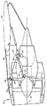
図において一貫して、同一の参照番号が同じ要素を示しており、これら図面を参照すると、図1は、航空機の翼14の下方に取付けられた縦方向すなわち軸線方向の中心線軸12を備えるターボファン式ガスタービンエンジン10を示している。翼14は、パイロン16を有し、エンジン10は、前方マウント18と、前方マウント18から軸に沿って下流側に離れた位置にある後方マウント20とを有する取付けシステムによって、パイロン16に取付けられている。エンジン10は、上部マウント取付によって取付けられるように示されているが、これは単に、図示の目的のためである。以下の説明から、本発明が、側部マウントや底部マウントを含むエンジン取付けのいかなる様式に使用されている取付けシステムの部品に対しても適用できることが理解できるであろう。従って、本発明は、翼に取付けるエンジンに限定されることなく、胴体や尾部に取付けられるエンジンに関しても用いることができる。さらに、本発明は、ターボファンエンジンに限定されず、ターボシャフトエンジンやターボプロップエンジンといった、他のタイプのエンジンに関しても用いることができる。
【0012】
前方マウント18は、ボルトのような通常の手段によってパイロン16に固定されている取付けフレーム22を有する。前部の取付けフレーム22は、一つ又はより多くのリンク24によってエンジン10に結合されているが、その箇所でリンク24の各々は、一端を前部の取付けフレーム22に、別の一端をエンジンのファンケーシング26に結合されている。後方マウント20は、やはりボルトのような通常の手段によってパイロン16に固定された取付けフレーム28を有する。エンジン10を後部の取付けフレーム28に結合するために、一つ又はより多くのリンク30が使用される。具体的に述べると、リンク30の各々は、一端を後部の取付けフレーム28に、別の一端をエンジンのコアエンジンケーシング32又は他のエンジン固定構造体に結合されている。従って、エンジンの垂直方向、横方向および横揺れの荷重は、前部と後部の取付けリンク24と30を通して反作用的に受けられる。さらに、後方マウント20は、エンジン10が発生させるスラストに反作用を与えるための、少なくとも1つのスラストリンク34を備えている。スラストリンク34は、一端を後部取付けフレーム28に、別の一端をエンジンのフロントフレーム36のようなエンジンの固定構造体に結合されている。
【0013】
次に、図2と図3を参照すると、スラストリンク34が、より詳細に示されている。本発明の概念は、ここではスラストリンクへの適用として述べられるが、本発明がスラストリンクに限定されるものではないことに注意すべきである。実際、本発明は、数多くの取付けシステムの部品に適用することが可能で、共振振動数が、通常、エンジンの励振振動数に近接する、細長い形状をした、どんな部品についても有用である。
【0014】
スラストリンク34は細長いスパン部38を有し、スパン部38の両端にはコネクタ40が形成されている。図2に示されているように、コネクタ40の各々は、軸線方向に延びる1対の平行なアーム42を備え、それぞれのアーム42に穴44が形成されたクレビスの形状である。従って、コネクタ40は、穴44と他の取付け構造に形成されている孔の両方を通るボルトやピン(図示されていない)によって、他の取付け構造体に結合することができる。コネクタ40は、クレビス形状として示されてはいるが、スラストリンク34の端部を取付けシステムの適切な構造体に結合することのできる、どんな様式の結合構造体であっても良い。
【0015】
スパン部38は、振動応答を最小にできるように、スラストリンク34の共振振動数をエンジン励振振動数から離れた値に定めるため、一体に形成された拡大部すなわち集中質量46を備えている。これを、ここでは、スラストリンク34の「振動数設定」と呼ぶ。集中質量46が備えられていることにより、リンクのこわさと質量の比が変わり、そのため、スラストリンク34の共振振動数は、スパン部が均一な横断面を有する場合の共振振動数と異なるものとなる。このために、エンジン10による励振は、最小にされるか、もしくは排除される。具体的に述べると、リンクの共振振動数をエンジンファンロータの最大回転速度とエンジンコアロータの最小回転速度の間の値まで下げるように、集中質量46の重さと位置が選択される。
【0016】
集中質量46の重さと配置は、システム全体の分析により決定され、スラストリンク34の全長といった数多くの要因に基づく、個々の用途に依存する。集中質量46は、一般に、スパン部38上の、2つのコネクタ間の何れかの箇所に配置される。集中質量46は、一般に振動モードの波腹に配置するとより有効であるので、必ずしも必要ではないが、集中質量46をそのような位置に配置することが好ましい。スラストリンク34の重量と強度に対するインパクトを可能な限り小さくしながら、望ましい振動数設定を達成するために、集中質量46の重量と配置が選択される。
【0017】
本発明は、中実のリンクにも適用できるが、図3に最も良く示されているように、スラストリンク34は、中空である。リンクが中空であることによって、取付けシステム全体の重量が小さくなり、中空の断面は、概して、座屈に対して抵抗がより高い。中空のリンクにおいては、スラストリンク34の2つの空洞部を流体的に接続するために、集中質量46に、軸線方向に延びているドレン孔48が設けられる。このことにより、スラストリンク34内部における流体のトラッピングを防ぐことができる。
【0018】
次に、図4を参照すると、本発明の第2の実施形態が示されている。ここでは、スラストリンク134は細長いスパン部138を有し、スパン部138の両端に、コネクタ140が形成されている。本発明の第1の実施形態におけるように、コネクタ140の各々は、クレビスの形状をしており、軸線方向に延びる一対の平行なアーム142を備え、それぞれのアーム142に穴144が形成されている。従って、コネクタ140は、穴144と他の取付け構造体に形成されている孔の両方を通るボルトやピン(図示されていない)によって、他の取付け構造体に結合することができる。コネクタ140は、クレビス形状として示されているが、スラストリンク134の端部を取付けシステムの適切な構造体に結合することのできる、どんな様式の結合構造体であっても良い。
【0019】
スラストリンク134の共振振動数をエンジンの励振振動数から離れた値に定めるために、別個のおもりの形式をとる集中質量146が、スパン部138に取付けられている。集中質量146は、2つの半部すなわちセグメントからなり、そのセグメントの一つが、図5に示されている。円筒形のリンクに対応して、セグメント50は、凹状の面54の輪郭を定めるU形の本体を有する。取付けフランジ56が、セグメント本体52の両端から外側へ直角に延びている。2つの穴58が、適切な留め金具60(図4)を受けるために、それぞれの取付けフランジ56に形成されている。
【0020】
従って、集中質量146は、2つのセグメント50を、それに対応する、軸線方向に整合される取付けフランジとともに、スパン部138の直径方向相対向する位置にある両側面に配置することによって、スラストリンク134に取付けられる。凹状面54は、各対の取付けフランジ56の間にギャップができるように、スパン部138の面に嵌合する寸法に定められている。2つのセグメント50は、留め金具60によって固定されている。留め金具60は、ナットやボルトのようなどんな留め金具でも良く、これを締めることにより、すきまが閉じられ、集中質量146をスラストリンク134の適所にしっかりとクランプするための締りばめが生じる。集中質量146をスラストリンク134に取付けるには、他の方法も可能であることに注意すべきである。
【0021】
セグメント50は、十分な強度と耐食性を備えている、どんな材料からも作ることができる。代表的には、スラストリンク134の材料と同じか又はより大きな密度を有する材料でできている。セグメントの材料はまた、リンクの材料との電池対に対し抵抗性を備えていなければならない。
【0022】
別個の集中質量146は、第1の実施形態における一体に形成された集中質量とほぼ同じ原理で機能する。すなわち、集中質量146が取付けられることによって、スラストリンク134の共振振動数は、振動応答を最小にするために、エンジンの励振振動数から十分に離れた値へと転移する。上に述べた第1の実施形態におけると同様に、エンジンファンロータの最大回転速度とエンジンコアロータの最小回転速度の間の値までリンクの共振振動数を下げるように、かつ、重量効率の面においても同じ効果を上げるように、集中質量146の重量と配置が選択される。
【0023】
ここまで、エンジンの励振振動数に近接していない共振振動数をもつエンジン取付けシステムのためのリンク部品について述べてきた。実際問題として、エンジン取付けシステムにおける振動数設定のために集中質量を用いることで、システム設計全体の柔軟性はより大きなものとなる。求められている通り、重量効率の面で、比較的細長いリンク部品を集中質量とともに用いることにより、エンジンの励振振動数から部品の共振振動数を離れた値に効果的に定めることができる。共振振動数が効果的に定められていない、従来のリンク部品は、応答振動数を矯正する集中質量を取付けることにより、改良することができる。
【0024】
本発明のもう1つの好ましい特性は、集中質量の取付けによって共振振動数を「チューニング」できることである。分析による振動数予測は、しばしば予測し難い境界条件に敏感なので、この特性は、有用である。従って、予備分析を用いて、集中質量の初期の重量と配置に基づく振動数を予測することができる。このあとに、予備分析の試験を行い、集中質量の重量と配置のどちらか又は両方を変えて、共振振動数を「ファインチューニング」することができる。
【0025】
設計者は、集中質量の重量と配置を組み合わせることで、良好な値に定められた他のモードにほとんど影響を与えることなく、望ましくない共振振動数のモードを柔軟に変えることができる。このことは、集中質量を振動モードの波腹上或いは波腹間に配置することにより、達成される。他の振動数を変えることなく、1つのモードの共振振動数の値を変えることは、エンジンの励振振動数から離れた値に全てのモードを維持するために、しばしば必要となるので、この方法は、好ましいものである。
【0026】
本発明の実施の形態を詳細に述べてきたが、特許請求の範囲で規定されたような本発明の技術思想と技術的範囲から外れることなく、さまざまな改良を加えられることが、当業者には明らかであろう。
【図面の簡単な説明】
【図1】 本発明の取付けシステム部品を備えた航空機エンジンの側面図。
【図2】 図1の取付けシステムから取出したリンクの斜視図。
【図3】 図2のリンクの縦断面図。
【図4】 取付けシステムのリンクの別の実施形態の斜視図。
【図5】 図4のリンクから取出した集中質量のセグメントの斜視図。
【符号の説明】
34 スラストリンク
38 スパン部
40 コネクタ
42 アーム
46、146 集中質量
50 セグメント
52 セグメント本体
54 凹状の面
56 取付けフランジ
58 穴[0001]
BACKGROUND OF THE INVENTION
The present invention relates generally to aircraft engines, and more particularly to a mount for supporting an engine on an aircraft.
[0002]
[Prior art]
Aircraft engines are installed at various locations on the aircraft, such as the wings, fuselage, and tail. Engines are typically mounted at their front and rear ends by corresponding front and rear mounts to carry various loads on the aircraft. Loads generally include vertical loads such as the weight of the engine itself, axial loads due to thrust generated by the engine, lateral loads such as loads caused by wind buffeting, and rotational effects of the engine. Includes roll loads or moments. The mount must also be able to accommodate both axial and radial thermal expansion and contraction of the engine relative to the support structure.
[0003]
Engine mounts generally have a mounting frame, such as a pylon, fixed to the aircraft structure and a number of links that couple the engine to the mounting frame. Depending on the application, the connecting link needs to be a relatively long and thin part.
[0004]
[Problems to be solved by the invention]
The elongated parts of the mounting system may have low resonance frequencies that are close to or very close to the engine excitation frequency, such as the frequency produced by 1 / rev of engine operating speed. These modes will be excited by inherent vibrations caused by rotational imbalances in the low pressure or high pressure rotor of the engine. Mounting systems tend to have high amplitude vibration responses because they tend to be weakly damped. High amplitude vibrational responses can cause high-cycle fatigue, joint wear and / or repeated impact damage of the mounting components.
[0005]
Engine manufacturers generally rely on old-fashioned imbalance tests to find resonance frequency issues. Unfortunately, high engine imbalance events such as rotor blade failure cannot be practically tested because it is difficult to produce high imbalance effects for a time sufficient to collect frequency data. This makes it difficult to implement a mounting system that is tolerant of high engine imbalances.
[0006]
Currently, mounting systems are designed so that the resonant frequency of the component is not close to the engine's excitation frequency. This generally means that the link component length to diameter ratio is set so that the link's flexural resonance frequency is raised sufficiently far from the engine's excitation frequency to minimize vibration response. Is achieved by reducing. However, in many cases, the length of the link is determined by other design conditions, so reducing the length to diameter ratio generally results in an increase in the volume of the mounting link. Increasing the volume of the link increases the weight of the entire mounting system and adversely affects implementation problems in systems where only a limited amount of space is usually allocated for each part. Another possible method is to design the link to allow link resonance and withstand high cycle fatigue. This method can be very difficult for new designs because at the link design stage, the link's response to engine excitation is hardly known.
[0007]
Accordingly, it is desirable to have a link component for an engine mounting system that is designed to have a resonant frequency that is not in close proximity to the engine's excitation frequency and that minimizes current link weight and mounting issues.
[0008]
[Means for Solving the Problems]
The need stated above is met by the present invention which provides a link for an engine mounting system. The link includes a span portion having a first connector formed at one end and a second connector formed at another end. A concentrated mass is placed in the span to define the resonant frequency at a value away from the engine excitation frequency.
[0009]
The invention and its advantages over the prior art will become apparent upon reading the following detailed description and the appended claims with reference to the accompanying drawings.
[0010]
DETAILED DESCRIPTION OF THE INVENTION
The subject matter regarded as the invention is particularly pointed out and distinctly claimed at the beginning of the specification. However, the present invention can be best understood by referring to the following description in conjunction with the accompanying drawings.
[0011]
Throughout the figures, identical reference numerals indicate the same elements, and with reference to these figures, FIG. 1 is a turbo with a longitudinal or
[0012]
The
[0013]
2 and 3, the
[0014]
The thrust link 34 has an elongated
[0015]
The
[0016]
The weight and placement of the lumped
[0017]
Although the present invention is applicable to solid links, as best shown in FIG. 3, the
[0018]
Referring now to FIG. 4, a second embodiment of the present invention is shown. Here, the
[0019]
A lumped
[0020]
Thus, the lumped
[0021]
The
[0022]
The separate
[0023]
Thus far, a link component has been described for an engine mounting system having a resonant frequency not close to the engine's excitation frequency. In practice, the use of lumped mass to set the frequency in the engine mounting system provides greater flexibility in the overall system design. As required, in terms of weight efficiency, by using relatively elongated link components with concentrated mass, the resonant frequency of the component can be effectively determined to be a value away from the engine excitation frequency. Conventional link components where the resonant frequency is not effectively defined can be improved by attaching a concentrated mass that corrects the response frequency.
[0024]
Another preferred characteristic of the present invention is that the resonant frequency can be “tuned” by attachment of a concentrated mass. This property is useful because frequency prediction by analysis is often sensitive to boundary conditions that are difficult to predict. Therefore, the preliminary analysis can be used to predict the frequency based on the initial weight and placement of the concentrated mass. This can be followed by a preliminary analysis test to “fine tune” the resonant frequency by changing either or both the weight of the concentrated mass and / or the arrangement.
[0025]
By combining the weight and placement of the concentrated mass, the designer can flexibly change the mode of undesirable resonant frequencies with little impact on other modes set to good values. This is achieved by placing the concentrated mass on or between the antinodes of the vibration mode. This is because changing the value of the resonant frequency of one mode without changing the other frequency is often necessary to maintain all modes at values away from the engine excitation frequency. Is preferred.
[0026]
Although the embodiments of the present invention have been described in detail, those skilled in the art will recognize that various modifications can be made without departing from the spirit and scope of the present invention as defined in the claims. Will be clear.
[Brief description of the drawings]
FIG. 1 is a side view of an aircraft engine with mounting system components of the present invention.
FIG. 2 is a perspective view of a link taken from the mounting system of FIG.
3 is a longitudinal sectional view of the link of FIG.
FIG. 4 is a perspective view of another embodiment of a link of an attachment system.
FIG. 5 is a perspective view of a concentrated mass segment taken from the link of FIG. 4;
[Explanation of symbols]
34 Thrust link 38
Claims (8)
前記エンジンは前記エンジン取付けシステムにより前記航空機に取り付けられており、
前記エンジン取付けシステムはリンク(34、134)を含み、該リンクは、
スパン部(38、138)と、
前記スパン部(38、138)の一端に形成され、前記エンジンに結合された第1コネクタ(40、140)と、
前記スパン部(38、138)の別の一端に形成され、前記航空機に結合された第2コネクタ(40、140)と、
前記エンジン(10)の励振振動数から離れた値に前記エンジン取付けシステムの共振振動数を定めるための、前記スパン部に配置された集中質量(46、146)と、
を含むことを特徴とする航空機。An aircraft comprising an engine and an engine mounting system,
The engine is attached to the aircraft by the engine mounting system;
The engine mounting system includes links (34, 134), the links
Span portions (38, 138);
A first connector (40, 140) formed at one end of the span (38, 138) and coupled to the engine;
A second connector (40, 140) formed at another end of the span (38, 138) and coupled to the aircraft ;
A lumped mass (46, 146) disposed in the span for determining the resonant frequency of the engine mounting system at a value away from the excitation frequency of the engine (10);
An aircraft characterized by including:
Applications Claiming Priority (2)
| Application Number | Priority Date | Filing Date | Title |
|---|---|---|---|
| US09/608480 | 2000-06-30 | ||
| US09/608,480 US6330985B1 (en) | 2000-06-30 | 2000-06-30 | Link component for aircraft engine mounting systems |
Publications (3)
| Publication Number | Publication Date |
|---|---|
| JP2002173094A JP2002173094A (en) | 2002-06-18 |
| JP2002173094A5 JP2002173094A5 (en) | 2008-08-14 |
| JP4733296B2 true JP4733296B2 (en) | 2011-07-27 |
Family
ID=24436668
Family Applications (1)
| Application Number | Title | Priority Date | Filing Date |
|---|---|---|---|
| JP2001197581A Expired - Fee Related JP4733296B2 (en) | 2000-06-30 | 2001-06-29 | Link parts for aircraft engine mounting systems |
Country Status (6)
| Country | Link |
|---|---|
| US (1) | US6330985B1 (en) |
| EP (1) | EP1170207B1 (en) |
| JP (1) | JP4733296B2 (en) |
| BR (1) | BR0102647B1 (en) |
| CA (1) | CA2351281C (en) |
| DE (1) | DE60117931T2 (en) |
Families Citing this family (30)
| Publication number | Priority date | Publication date | Assignee | Title |
|---|---|---|---|---|
| US6659878B2 (en) * | 2001-03-30 | 2003-12-09 | General Electric Company | Method and apparatus for coupling male threads to female threads |
| US6755005B2 (en) | 2001-08-10 | 2004-06-29 | General Electric Company | Method and apparatus for stiffening and apparatus |
| US6607165B1 (en) * | 2002-06-28 | 2003-08-19 | General Electric Company | Aircraft engine mount with single thrust link |
| WO2004032762A1 (en) | 2002-10-04 | 2004-04-22 | Tyco Healthcare Group, Lp | Tool assembly for a surgical stapling device |
| US7093996B2 (en) * | 2003-04-30 | 2006-08-22 | General Electric Company | Methods and apparatus for mounting a gas turbine engine |
| FR2862944B1 (en) * | 2003-12-01 | 2006-02-24 | Airbus France | DEVICE FOR ATTACHING A TURBOPROPULSER UNDER AN AIRCRAFT VESSEL |
| US7391843B2 (en) * | 2005-06-20 | 2008-06-24 | General Electric Company | Systems and methods for adjusting noise in a medical imaging system |
| US8579176B2 (en) * | 2005-07-26 | 2013-11-12 | Ethicon Endo-Surgery, Inc. | Surgical stapling and cutting device and method for using the device |
| FR2891246B1 (en) * | 2005-09-26 | 2007-10-26 | Airbus France Sas | ENGINE ASSEMBLY FOR AN AIRCRAFT COMPRISING AN ENGINE AND A DEVICE FOR HITCHING SUCH AN ENGINE |
| GB0608983D0 (en) * | 2006-05-06 | 2006-06-14 | Rolls Royce Plc | Aeroengine mount |
| FR2903076B1 (en) * | 2006-06-30 | 2009-05-29 | Aircelle Sa | STRUCTURING LUGGAGE |
| FR2909974B1 (en) * | 2006-12-13 | 2009-02-06 | Aircelle Sa | NACELLE FOR TURBOJET DOUBLE FLOW |
| FR2934845A1 (en) * | 2008-08-11 | 2010-02-12 | Airbus France | ENGINE MAT FOR AN AIRCRAFT |
| DE102008044759B4 (en) * | 2008-08-28 | 2013-09-19 | Airbus Operations Gmbh | Support for an aircraft structural component which can be produced using the selective laser melting method |
| DE102009058359A1 (en) * | 2009-12-15 | 2011-06-16 | Airbus Operations Gmbh | Force introduction fitting for lightweight components |
| EP2752577B1 (en) | 2010-01-14 | 2020-04-01 | Senvion GmbH | Wind turbine rotor blade components and methods of making same |
| US10137542B2 (en) | 2010-01-14 | 2018-11-27 | Senvion Gmbh | Wind turbine rotor blade components and machine for making same |
| EP2688784B1 (en) * | 2011-03-21 | 2016-11-02 | 4Power4 Sprl | Steering mechanism |
| US8727269B2 (en) * | 2011-06-06 | 2014-05-20 | General Electric Company | System and method for mounting an aircraft engine |
| US9016623B2 (en) * | 2011-11-30 | 2015-04-28 | The Boeing Company | Jam protection and alleviation for control surface linkage mechanisms |
| US8950724B2 (en) * | 2012-06-28 | 2015-02-10 | Solar Turbines Inc. | Turbine engine mounting system and method |
| WO2015010315A1 (en) | 2013-07-26 | 2015-01-29 | Mra Systems, Inc. | Aircraft engine pylon |
| GB201414419D0 (en) | 2014-08-14 | 2014-10-01 | Rolls Royce Plc | Method of testing |
| US11066178B2 (en) | 2015-09-02 | 2021-07-20 | Raytheon Technologies Corporation | Link for aircraft component mounting |
| US10144525B2 (en) * | 2015-09-24 | 2018-12-04 | Embraer S.A. | Aircraft engine pylon to wing mounting assembly |
| US9868539B2 (en) * | 2015-09-24 | 2018-01-16 | Embraer S.A. | Aircraft engine pylon to wing mounting assembly |
| WO2018116083A1 (en) * | 2016-12-20 | 2018-06-28 | Bombardier Inc. | Thrust link with tuned absorber |
| FR3079873B1 (en) * | 2018-04-04 | 2020-05-08 | Safran Aircraft Engines | ENGINE ASSEMBLY FOR AN AIRCRAFT HAVING A FEEDING PATH FOR A TANK OF A TURBOMACHINE INTER-VEIN COMPARTMENT |
| GB201900609D0 (en) | 2019-01-16 | 2019-03-06 | Rolls Royce Plc | Mounting apparatus for gas turbine engine |
| CN112849418B (en) * | 2019-11-27 | 2022-12-16 | 中国航发商用航空发动机有限责任公司 | Aircraft engine mounting system and aircraft |
Family Cites Families (9)
| Publication number | Priority date | Publication date | Assignee | Title |
|---|---|---|---|---|
| US2317501A (en) * | 1941-03-21 | 1943-04-27 | United Aircraft Corp | Friction damped engine mount |
| FR967640A (en) * | 1948-06-03 | 1950-11-08 | Mounting and fixing of a turbo-propeller in the airframe of an airplane | |
| US4437627A (en) * | 1982-03-12 | 1984-03-20 | The Boeing Company | Integrated power plant installation system |
| US4603821A (en) * | 1983-12-30 | 1986-08-05 | The Boeing Company | System for mounting a jet engine |
| US5244170A (en) * | 1991-10-15 | 1993-09-14 | General Dynamics Corporation, Space Systems Division | Passive nonlinear interface strut (PNIS) |
| FR2728538A1 (en) * | 1994-12-23 | 1996-06-28 | Eurocopter France | ANTI-VIBRATORY SUSPENSION OF HELICOPTER ROTOR |
| US5845236A (en) * | 1996-10-16 | 1998-12-01 | Lord Corporation | Hybrid active-passive noise and vibration control system for aircraft |
| DE19713365C1 (en) * | 1997-04-01 | 1998-10-22 | Deutsch Zentr Luft & Raumfahrt | Engine suspension, in particular for propeller aircraft, with a rod assembly for fastening an engine |
| US6212974B1 (en) * | 1998-12-17 | 2001-04-10 | United Technologies Corporation | Variable stiffness positioning link for a gearbox |
-
2000
- 2000-06-30 US US09/608,480 patent/US6330985B1/en not_active Expired - Lifetime
-
2001
- 2001-06-21 CA CA002351281A patent/CA2351281C/en not_active Expired - Fee Related
- 2001-06-27 EP EP01305603A patent/EP1170207B1/en not_active Expired - Lifetime
- 2001-06-27 DE DE60117931T patent/DE60117931T2/en not_active Expired - Fee Related
- 2001-06-29 JP JP2001197581A patent/JP4733296B2/en not_active Expired - Fee Related
- 2001-06-29 BR BRPI0102647-0A patent/BR0102647B1/en not_active IP Right Cessation
Also Published As
| Publication number | Publication date |
|---|---|
| EP1170207A3 (en) | 2003-04-23 |
| JP2002173094A (en) | 2002-06-18 |
| US6330985B1 (en) | 2001-12-18 |
| DE60117931T2 (en) | 2006-11-23 |
| EP1170207A2 (en) | 2002-01-09 |
| BR0102647A (en) | 2002-02-13 |
| CA2351281C (en) | 2008-03-18 |
| CA2351281A1 (en) | 2001-12-30 |
| EP1170207B1 (en) | 2006-03-15 |
| DE60117931D1 (en) | 2006-05-11 |
| BR0102647B1 (en) | 2010-08-10 |
Similar Documents
| Publication | Publication Date | Title |
|---|---|---|
| JP4733296B2 (en) | Link parts for aircraft engine mounting systems | |
| EP1157925B1 (en) | Snubber thrust mount | |
| US8418474B2 (en) | Altering a natural frequency of a gas turbine transition duct | |
| US7942580B2 (en) | Rear suspension for an aircraft engine with shackle in waiting and spring for such a hinge pin in waiting | |
| US6796765B2 (en) | Methods and apparatus for assembling gas turbine engine struts | |
| US4832568A (en) | Turbomachine airfoil mounting assembly | |
| US10138754B2 (en) | Device for measuring aerodynamic magnitudes intended to be placed in a flow passage of a turbine engine | |
| US3745629A (en) | Method of determining optimal shapes for stator blades | |
| JP4498694B2 (en) | Aircraft engine mount with a single thrust link | |
| EP0839260B1 (en) | Vibration damping shroud for a turbomachine vane | |
| RU2503825C2 (en) | Vibration damping device for attachments of blades of gas bladed machines, gas bladed machine, gas-turbine engine and high-speed propeller engine | |
| US11156129B2 (en) | Turbine engine casing | |
| JPH04259629A (en) | Shround support body for damping | |
| JP5796833B2 (en) | Gas turbine engine components | |
| US9988931B2 (en) | Turbine exhaust cylinder/ turbine exhaust manifold bolted part span turbine exhaust flaps | |
| RU2666030C1 (en) | Guide arm for elongated members, particularly for turbomachines | |
| US11440669B2 (en) | Integrated support structure for an aircraft engine and its auxiliary components | |
| EP3712391B1 (en) | Strut dampening assembly and method of making same | |
| EP3683148B1 (en) | Mounting apparatus for a gas turbine engine | |
| CN111608750B (en) | Turbine engine housing | |
| US20080063522A1 (en) | Array of components |
Legal Events
| Date | Code | Title | Description |
|---|---|---|---|
| A521 | Request for written amendment filed |
Free format text: JAPANESE INTERMEDIATE CODE: A523 Effective date: 20080620 |
|
| A621 | Written request for application examination |
Free format text: JAPANESE INTERMEDIATE CODE: A621 Effective date: 20080620 |
|
| RD02 | Notification of acceptance of power of attorney |
Free format text: JAPANESE INTERMEDIATE CODE: A7422 Effective date: 20101116 |
|
| RD04 | Notification of resignation of power of attorney |
Free format text: JAPANESE INTERMEDIATE CODE: A7424 Effective date: 20101116 |
|
| A131 | Notification of reasons for refusal |
Free format text: JAPANESE INTERMEDIATE CODE: A131 Effective date: 20101130 |
|
| A521 | Request for written amendment filed |
Free format text: JAPANESE INTERMEDIATE CODE: A523 Effective date: 20110228 |
|
| RD02 | Notification of acceptance of power of attorney |
Free format text: JAPANESE INTERMEDIATE CODE: A7422 Effective date: 20110228 |
|
| RD04 | Notification of resignation of power of attorney |
Free format text: JAPANESE INTERMEDIATE CODE: A7424 Effective date: 20110228 |
|
| A01 | Written decision to grant a patent or to grant a registration (utility model) |
Free format text: JAPANESE INTERMEDIATE CODE: A01 Effective date: 20110329 |
|
| A61 | First payment of annual fees (during grant procedure) |
Free format text: JAPANESE INTERMEDIATE CODE: A61 Effective date: 20110422 |
|
| FPAY | Renewal fee payment (event date is renewal date of database) |
Free format text: PAYMENT UNTIL: 20140428 Year of fee payment: 3 |
|
| R150 | Certificate of patent or registration of utility model |
Free format text: JAPANESE INTERMEDIATE CODE: R150 |
|
| R250 | Receipt of annual fees |
Free format text: JAPANESE INTERMEDIATE CODE: R250 |
|
| R250 | Receipt of annual fees |
Free format text: JAPANESE INTERMEDIATE CODE: R250 |
|
| R250 | Receipt of annual fees |
Free format text: JAPANESE INTERMEDIATE CODE: R250 |
|
| LAPS | Cancellation because of no payment of annual fees |