JP4733016B2 - Writing instrument with cushioning element - Google Patents
Writing instrument with cushioning element Download PDFInfo
- Publication number
- JP4733016B2 JP4733016B2 JP2006507156A JP2006507156A JP4733016B2 JP 4733016 B2 JP4733016 B2 JP 4733016B2 JP 2006507156 A JP2006507156 A JP 2006507156A JP 2006507156 A JP2006507156 A JP 2006507156A JP 4733016 B2 JP4733016 B2 JP 4733016B2
- Authority
- JP
- Japan
- Prior art keywords
- writing
- cartridge
- shaft
- proximal
- writing instrument
- Prior art date
- Legal status (The legal status is an assumption and is not a legal conclusion. Google has not performed a legal analysis and makes no representation as to the accuracy of the status listed.)
- Expired - Fee Related
Links
- 239000000463 material Substances 0.000 claims description 34
- 238000007906 compression Methods 0.000 claims description 27
- 230000006835 compression Effects 0.000 claims description 24
- 238000009423 ventilation Methods 0.000 claims description 7
- 230000036316 preload Effects 0.000 claims description 5
- 239000013013 elastic material Substances 0.000 claims 6
- 238000000034 method Methods 0.000 description 12
- 238000001746 injection moulding Methods 0.000 description 8
- 230000000670 limiting effect Effects 0.000 description 5
- 238000000465 moulding Methods 0.000 description 5
- 238000004519 manufacturing process Methods 0.000 description 4
- 238000003466 welding Methods 0.000 description 4
- 230000003139 buffering effect Effects 0.000 description 3
- 230000003247 decreasing effect Effects 0.000 description 3
- 230000004048 modification Effects 0.000 description 3
- 238000012986 modification Methods 0.000 description 3
- SCUZVMOVTVSBLE-UHFFFAOYSA-N prop-2-enenitrile;styrene Chemical compound C=CC#N.C=CC1=CC=CC=C1 SCUZVMOVTVSBLE-UHFFFAOYSA-N 0.000 description 3
- 230000002829 reductive effect Effects 0.000 description 3
- 229920000638 styrene acrylonitrile Polymers 0.000 description 3
- 238000013022 venting Methods 0.000 description 3
- PPBRXRYQALVLMV-UHFFFAOYSA-N Styrene Chemical compound C=CC1=CC=CC=C1 PPBRXRYQALVLMV-UHFFFAOYSA-N 0.000 description 2
- 239000000853 adhesive Substances 0.000 description 2
- 230000001070 adhesive effect Effects 0.000 description 2
- 230000008859 change Effects 0.000 description 2
- 238000013016 damping Methods 0.000 description 2
- 230000000694 effects Effects 0.000 description 2
- 229920001971 elastomer Polymers 0.000 description 2
- 239000012530 fluid Substances 0.000 description 2
- 239000006260 foam Substances 0.000 description 2
- 238000002347 injection Methods 0.000 description 2
- 239000007924 injection Substances 0.000 description 2
- 230000013011 mating Effects 0.000 description 2
- 230000000717 retained effect Effects 0.000 description 2
- 230000002441 reversible effect Effects 0.000 description 2
- 238000000926 separation method Methods 0.000 description 2
- 230000000087 stabilizing effect Effects 0.000 description 2
- 238000006467 substitution reaction Methods 0.000 description 2
- 239000000758 substrate Substances 0.000 description 2
- 229920001169 thermoplastic Polymers 0.000 description 2
- 229920005992 thermoplastic resin Polymers 0.000 description 2
- 206010003497 Asphyxia Diseases 0.000 description 1
- 235000009161 Espostoa lanata Nutrition 0.000 description 1
- 240000001624 Espostoa lanata Species 0.000 description 1
- CWYNVVGOOAEACU-UHFFFAOYSA-N Fe2+ Chemical compound [Fe+2] CWYNVVGOOAEACU-UHFFFAOYSA-N 0.000 description 1
- DHKHKXVYLBGOIT-UHFFFAOYSA-N acetaldehyde Diethyl Acetal Natural products CCOC(C)OCC DHKHKXVYLBGOIT-UHFFFAOYSA-N 0.000 description 1
- 125000002777 acetyl group Chemical class [H]C([H])([H])C(*)=O 0.000 description 1
- XECAHXYUAAWDEL-UHFFFAOYSA-N acrylonitrile butadiene styrene Chemical compound C=CC=C.C=CC#N.C=CC1=CC=CC=C1 XECAHXYUAAWDEL-UHFFFAOYSA-N 0.000 description 1
- 238000007792 addition Methods 0.000 description 1
- 230000015572 biosynthetic process Effects 0.000 description 1
- 230000000903 blocking effect Effects 0.000 description 1
- 229910010293 ceramic material Inorganic materials 0.000 description 1
- 239000002131 composite material Substances 0.000 description 1
- 239000000470 constituent Substances 0.000 description 1
- 239000002989 correction material Substances 0.000 description 1
- 239000000806 elastomer Substances 0.000 description 1
- 239000013536 elastomeric material Substances 0.000 description 1
- 230000007613 environmental effect Effects 0.000 description 1
- 239000003292 glue Substances 0.000 description 1
- 238000003754 machining Methods 0.000 description 1
- 239000002184 metal Substances 0.000 description 1
- 239000012778 molding material Substances 0.000 description 1
- 230000007935 neutral effect Effects 0.000 description 1
- 239000004033 plastic Substances 0.000 description 1
- 229920003023 plastic Polymers 0.000 description 1
- 239000004417 polycarbonate Substances 0.000 description 1
- 229920000515 polycarbonate Polymers 0.000 description 1
- 238000003825 pressing Methods 0.000 description 1
- 230000004044 response Effects 0.000 description 1
- 230000004043 responsiveness Effects 0.000 description 1
- 230000000284 resting effect Effects 0.000 description 1
- 230000006641 stabilisation Effects 0.000 description 1
- 238000011105 stabilization Methods 0.000 description 1
- 239000000126 substance Substances 0.000 description 1
- 229920002725 thermoplastic elastomer Polymers 0.000 description 1
- 239000012780 transparent material Substances 0.000 description 1
- 230000000007 visual effect Effects 0.000 description 1
Images


Classifications
-
- B—PERFORMING OPERATIONS; TRANSPORTING
- B43—WRITING OR DRAWING IMPLEMENTS; BUREAU ACCESSORIES
- B43M—BUREAU ACCESSORIES NOT OTHERWISE PROVIDED FOR
- B43M11/00—Hand or desk devices of the office or personal type for applying liquid, other than ink, by contact to surfaces, e.g. for applying adhesive
- B43M11/06—Hand-held devices
- B43M11/08—Hand-held devices of the fountain-pen type
- B43M11/085—Hand-held devices of the fountain-pen type with ball points
-
- B—PERFORMING OPERATIONS; TRANSPORTING
- B43—WRITING OR DRAWING IMPLEMENTS; BUREAU ACCESSORIES
- B43K—IMPLEMENTS FOR WRITING OR DRAWING
- B43K21/00—Propelling pencils
- B43K21/02—Writing-core feeding mechanisms
-
- B—PERFORMING OPERATIONS; TRANSPORTING
- B29—WORKING OF PLASTICS; WORKING OF SUBSTANCES IN A PLASTIC STATE IN GENERAL
- B29C—SHAPING OR JOINING OF PLASTICS; SHAPING OF MATERIAL IN A PLASTIC STATE, NOT OTHERWISE PROVIDED FOR; AFTER-TREATMENT OF THE SHAPED PRODUCTS, e.g. REPAIRING
- B29C45/00—Injection moulding, i.e. forcing the required volume of moulding material through a nozzle into a closed mould; Apparatus therefor
- B29C45/14—Injection moulding, i.e. forcing the required volume of moulding material through a nozzle into a closed mould; Apparatus therefor incorporating preformed parts or layers, e.g. injection moulding around inserts or for coating articles
- B29C45/14336—Coating a portion of the article, e.g. the edge of the article
- B29C45/14426—Coating the end of wire-like or rod-like or cable-like or blade-like or belt-like articles
-
- B—PERFORMING OPERATIONS; TRANSPORTING
- B29—WORKING OF PLASTICS; WORKING OF SUBSTANCES IN A PLASTIC STATE IN GENERAL
- B29C—SHAPING OR JOINING OF PLASTICS; SHAPING OF MATERIAL IN A PLASTIC STATE, NOT OTHERWISE PROVIDED FOR; AFTER-TREATMENT OF THE SHAPED PRODUCTS, e.g. REPAIRING
- B29C45/00—Injection moulding, i.e. forcing the required volume of moulding material through a nozzle into a closed mould; Apparatus therefor
- B29C45/16—Making multilayered or multicoloured articles
-
- B—PERFORMING OPERATIONS; TRANSPORTING
- B43—WRITING OR DRAWING IMPLEMENTS; BUREAU ACCESSORIES
- B43K—IMPLEMENTS FOR WRITING OR DRAWING
- B43K1/00—Nibs; Writing-points
- B43K1/06—Tubular writing-points
-
- B—PERFORMING OPERATIONS; TRANSPORTING
- B43—WRITING OR DRAWING IMPLEMENTS; BUREAU ACCESSORIES
- B43K—IMPLEMENTS FOR WRITING OR DRAWING
- B43K17/00—Continuously-adjustable nibs, e.g. for drawing-pens; Holders therefor
- B43K17/005—Continuously-adjustable nibs, e.g. for drawing-pens; Holders therefor continuously-adjustable nibs
-
- B—PERFORMING OPERATIONS; TRANSPORTING
- B43—WRITING OR DRAWING IMPLEMENTS; BUREAU ACCESSORIES
- B43K—IMPLEMENTS FOR WRITING OR DRAWING
- B43K24/00—Mechanisms for selecting, projecting, retracting or locking writing units
-
- B—PERFORMING OPERATIONS; TRANSPORTING
- B43—WRITING OR DRAWING IMPLEMENTS; BUREAU ACCESSORIES
- B43K—IMPLEMENTS FOR WRITING OR DRAWING
- B43K5/00—Pens with ink reservoirs in holders, e.g. fountain-pens
- B43K5/005—Pen barrels
-
- B—PERFORMING OPERATIONS; TRANSPORTING
- B43—WRITING OR DRAWING IMPLEMENTS; BUREAU ACCESSORIES
- B43K—IMPLEMENTS FOR WRITING OR DRAWING
- B43K5/00—Pens with ink reservoirs in holders, e.g. fountain-pens
- B43K5/16—Pens with ink reservoirs in holders, e.g. fountain-pens with retractable nibs
-
- B—PERFORMING OPERATIONS; TRANSPORTING
- B43—WRITING OR DRAWING IMPLEMENTS; BUREAU ACCESSORIES
- B43K—IMPLEMENTS FOR WRITING OR DRAWING
- B43K5/00—Pens with ink reservoirs in holders, e.g. fountain-pens
- B43K5/18—Arrangements for feeding the ink to the nibs
-
- B—PERFORMING OPERATIONS; TRANSPORTING
- B43—WRITING OR DRAWING IMPLEMENTS; BUREAU ACCESSORIES
- B43K—IMPLEMENTS FOR WRITING OR DRAWING
- B43K7/00—Ball-point pens
- B43K7/02—Ink reservoirs; Ink cartridges
- B43K7/03—Ink reservoirs; Ink cartridges pressurised, e.g. by gas
-
- B—PERFORMING OPERATIONS; TRANSPORTING
- B43—WRITING OR DRAWING IMPLEMENTS; BUREAU ACCESSORIES
- B43L—ARTICLES FOR WRITING OR DRAWING UPON; WRITING OR DRAWING AIDS; ACCESSORIES FOR WRITING OR DRAWING
- B43L19/00—Erasers, rubbers, or erasing devices; Holders therefor
- B43L19/0018—Erasers, rubbers, or erasing devices; Holders therefor with fluids
-
- B—PERFORMING OPERATIONS; TRANSPORTING
- B29—WORKING OF PLASTICS; WORKING OF SUBSTANCES IN A PLASTIC STATE IN GENERAL
- B29L—INDEXING SCHEME ASSOCIATED WITH SUBCLASS B29C, RELATING TO PARTICULAR ARTICLES
- B29L2031/00—Other particular articles
- B29L2031/725—Drawing or writing equipment
- B29L2031/7252—Pens, ball-point pens
-
- B—PERFORMING OPERATIONS; TRANSPORTING
- B29—WORKING OF PLASTICS; WORKING OF SUBSTANCES IN A PLASTIC STATE IN GENERAL
- B29L—INDEXING SCHEME ASSOCIATED WITH SUBCLASS B29C, RELATING TO PARTICULAR ARTICLES
- B29L2031/00—Other particular articles
- B29L2031/774—Springs
-
- B—PERFORMING OPERATIONS; TRANSPORTING
- B33—ADDITIVE MANUFACTURING TECHNOLOGY
- B33Y—ADDITIVE MANUFACTURING, i.e. MANUFACTURING OF THREE-DIMENSIONAL [3-D] OBJECTS BY ADDITIVE DEPOSITION, ADDITIVE AGGLOMERATION OR ADDITIVE LAYERING, e.g. BY 3-D PRINTING, STEREOLITHOGRAPHY OR SELECTIVE LASER SINTERING
- B33Y80/00—Products made by additive manufacturing
Landscapes
- Engineering & Computer Science (AREA)
- Mechanical Engineering (AREA)
- Manufacturing & Machinery (AREA)
- Pens And Brushes (AREA)
- Mechanical Pencils And Projecting And Retracting Systems Therefor, And Multi-System Writing Instruments (AREA)
- Injection Moulding Of Plastics Or The Like (AREA)
Description
本発明は、緩衝要素付きの筆記具に関する。特に、本発明は、筆記具の後側の非筆記端部のに設けられ、筆記具の筆記先端部が筆記中に筆記具の筆記先端部に加えられる力に応動できるようにし、それにより筆記中、ユーザに或る特定の感触を与える緩衝要素に関する。 The present invention relates to a writing instrument with a buffer element. In particular, the present invention is provided at the non-writing end portion on the rear side of the writing instrument, so that the writing tip portion of the writing instrument can respond to the force applied to the writing tip portion of the writing instrument during writing, thereby allowing the user to The present invention relates to a shock-absorbing element that gives a certain feeling to the.
(関連出願の参照)
本願は、2003年3月14日に出願された米国特許出願第10/389,300号の一部継続出願であり、この出願の記載内容全体を参照によりここに引用する。
(Refer to related applications)
This application is a continuation-in-part of US patent application Ser. No. 10 / 389,300, filed Mar. 14, 2003, the entire contents of which are hereby incorporated by reference.
一般に、筆記具、例えばペンは、本体を有し、この本体の中に、筆記先端部付きのカートリッジが定位置に保持されて、ユーザが筆記具を用いて筆記をすることができるようになっている。大抵の筆記具の場合、筆記先端部は、筆記中、筆記具の残部に対して実質的に剛性の(剛直な)関係をなして保持される。しかしながら、或る場合には、緩衝要素、例えばばね又は他の付勢要素が、筆記具内のカートリッジ及びかくして筆記先端部を非剛性的に保持する。緩衝要素により、筆記先端部を力が筆記中筆記先端部に加えられたときに筆記具の本体内へ付勢することができる。これにより、筆記中ユーザに望ましいと感じられる場合のある或る特定の感触が与えられる。 In general, a writing instrument such as a pen has a main body, and a cartridge with a writing tip is held in a fixed position in the main body so that a user can write using the writing instrument. . In most writing instruments, the writing tip is held in a substantially rigid (rigid) relationship with the rest of the writing instrument during writing. However, in some cases, a dampening element, such as a spring or other biasing element, holds the cartridge in the writing instrument and thus the writing tip non-rigidly. The cushioning element can bias the writing tip into the body of the writing instrument when force is applied to the writing tip during writing. This gives a certain feel that may be desirable to the user during writing.
緩衝要素を用いることは、先行技術において周知である。例えば、緩衝作用を筆記先端部にもたらすためにばね要素が用いられている。他の要素、例えばフォームインサートも又、先行技術において見受けられる。しかしながら、先行技術における緩衝要素の全ては、筆記具の残部とは別体の要素である。かくして、別々に形成された緩衝要素を筆記具の他の部分に取り付け又は結合しなければならず、筆記具の製造及び(又は)組立ての複雑さが増す。また、別の要素を筆記具に追加することにより、筆記具の種々の要素の相互取付けに何らかの故障が生じる恐れがあり、筆記具の全体的な信頼性が損なわれる。
かくして、いつでも筆記具と組み立てることができるよう形成され、製造が容易な筆記先端部用の緩衝要素を備えた筆記具が要望され続けている。
The use of cushioning elements is well known in the prior art. For example, a spring element is used to provide a buffering action on the writing tip. Other elements, such as foam inserts, are also found in the prior art. However, all of the cushioning elements in the prior art are separate elements from the rest of the writing instrument. Thus, separately formed cushioning elements must be attached or joined to other parts of the writing instrument, increasing the complexity of writing instrument manufacture and / or assembly. Also, adding another element to the writing instrument can cause some failure in the mutual attachment of the various elements of the writing instrument, impairing the overall reliability of the writing instrument.
Thus, there continues to be a need for a writing instrument with a cushioning element for the writing tip that is formed and ready to be assembled with the writing instrument at any time.
加うるに、弾性要素は、繰り返しの使用時に又は使い過ぎ又は乱暴な扱いの際に摩耗しやすく又は作用効果が減少しやすい場合がある。例えば、筆記具の筆記先端部用の緩衝要素は、繰り返し用いた後又は過剰圧縮の際にその弾性を失う場合がある。過剰に用いられ又は乱暴に用いられると、緩衝要素は、平べったくなり又は永久歪を起こし、或いはそれとは違った風に作用効果を失う場合がある。したがって、緩衝要素のかかる作用効果が失われる恐れを減少させることが望ましい。 In addition, the elastic element may be subject to wear or reduced effectiveness during repeated use or overuse or rough handling. For example, a cushioning element for the writing tip of a writing instrument may lose its elasticity after repeated use or upon over-compression. When used excessively or violently, the cushioning element may flatten or become permanently distorted or lose its effect in a different wind. Therefore, it is desirable to reduce the risk of losing such operational effects of the buffer element.
本発明の一特徴は、緩衝器具を備えた筆記具であって、この緩衝器具が筆記具の別の要素と一体に形成されている筆記具を提供する。筆記具は、軸と、筆記先端部を備えたカートリッジと、端栓とを有する。一実施形態においては、緩衝要素が筆記具の一部、例えば端栓と一体に形成される。例示の実施形態では、緩衝要素は、ばね要素である。カートリッジを緩衝要素により筆記具の軸内に定位置に保持することができ、この緩衝要素は、軸の近位端部に結合される。緩衝要素は、筆記先端部を軸方向に筆記先端部から押し出し、それにより、筆記先端部が力が筆記中又はマーキング中に筆記先端部に加えられると、筆記具の本体内へ軸方向に変位できる。これにより、筆記中に伝達される或る特定の感触がユーザに与えられるのを促進される。さらに、緩衝要素は好ましくは、端栓を射出成形法により形成できるよう構成されている。 One aspect of the present invention provides a writing instrument having a cushioning instrument, wherein the cushioning instrument is formed integrally with another element of the writing instrument. The writing instrument has a shaft, a cartridge provided with a writing tip, and an end plug. In one embodiment, the cushioning element is formed integrally with a portion of the writing instrument, such as an end plug. In the illustrated embodiment, the cushioning element is a spring element. The cartridge can be held in place within the axis of the writing instrument by a cushioning element, which is coupled to the proximal end of the shaft. The cushioning element pushes the writing tip axially from the writing tip so that it can be displaced axially into the body of the writing instrument when force is applied to the writing tip during writing or marking . This facilitates giving the user a certain feel that is transmitted during writing. Furthermore, the cushioning element is preferably configured such that the end plug can be formed by injection molding.
本発明は、緩衝要素を備えた筆記具であって、この緩衝要素が筆記具の別の要素と一体形成されている筆記具を提供する。これは、クッション要素と筆記具の別の要素の両方を完全に形成した後に後で緩衝要素と筆記具の別の要素の組立て又は相互取付けを必要とする先行技術とは区別される。本発明の筆記具では、緩衝要素及び緩衝要素が一体に形成された要素は、分離不能であり、これら要素の形成方法をいったん完了すると一要素として働き、筆記具に用いる前に互いにそれ以上組み立てたり取り付ける必要はない。 The present invention provides a writing instrument having a cushioning element, wherein the cushioning element is integrally formed with another element of the writing instrument. This is distinct from the prior art, which requires the assembly or interconnection of the cushioning element and another element of the writing instrument after the cushion element and another element of the writing instrument have been completely formed. In the writing instrument of the present invention, the cushioning element and the element in which the cushioning element is integrally formed are inseparable, and once the forming method of these elements is completed, it works as one element and is further assembled and attached to each other before being used in the writing instrument. There is no need.
本発明の上述の特徴とは別個独立であってもよく又は本発明の上述の特徴と組み合わせて利用できる本発明の別の特徴によれば、緩衝要素は、様々なばね定数を有するよう形成されたものであるのがよい。緩衝要素がコイルばねの形態をしている場合、コイルばねそれ自体を可変ばね定数を有するよう形成することにより可変ばね定数をもたらすことができる。例えば、コイルばねのコイル相互間の距離は、コイルが次々に底に突き当たるよう様々であってよい。コイルが底に突き当たる度に、ばねのばね定数が増大する。 According to another feature of the present invention that may be independent of the above-described features of the present invention or may be utilized in combination with the above-described features of the present invention, the dampening element may be formed to have various spring constants. It is good to be. If the damping element is in the form of a coil spring, the variable spring constant can be provided by forming the coil spring itself to have a variable spring constant. For example, the distance between the coils of the coil spring may vary so that the coils hit the bottom one after another. Each time the coil hits the bottom, the spring constant of the spring increases.
本発明の上述の特徴のうち任意のもの又は全てと共に利用できる本発明の更に別の特徴によれば、緩衝要素の圧縮度を制限するために停止要素を設けるのがよい。例えば、緩衝要素がコイルばねの形態をしている場合、停止要素は、コイルばね内で軸方向に且つこれを貫通して延びる停止ピンの形態をしているのがよい。停止ピンは、コイルばねの長さよりも短く、したがってコイルばねが停止ピンにより妨げられることなく、所定の圧縮の度合いまで自由に縮むことができるようになっている。かかる所定の圧縮度合いにいったん達すると、停止ピンは、ばねのそれ以上の圧縮を妨害し又は阻止する。 According to yet another feature of the present invention that can be utilized with any or all of the above features of the present invention, a stop element may be provided to limit the degree of compression of the cushioning element. For example, if the cushioning element is in the form of a coil spring, the stop element may be in the form of a stop pin that extends axially and through the coil spring. The stop pin is shorter than the length of the coil spring, so that the coil spring can be freely shrunk to a predetermined degree of compression without being blocked by the stop pin. Once such a predetermined degree of compression has been reached, the stop pin prevents or prevents further compression of the spring.
本発明の上述の特徴は単一又は組み合わせて利用できることは理解されよう。例えば、緩衝要素がコイルばねであり且つ停止要素がコイルばね内にこれを貫通して設けられた停止ピンの形態をしていてもよい。停止ピンは、ばね定数がより高くてもそのばねのそれ以上の圧縮を許容するよう幾分又は適度に弾性又は弾力があってもよい。したがって、停止ピンと組み合わせられたコイルばねは、可変ばね定数を備える緩衝要素を形成する。 It will be understood that the above-described features of the invention can be utilized singly or in combination. For example, the buffer element may be a coil spring and the stop element may be in the form of a stop pin provided through the coil spring. The stop pin may be somewhat or reasonably elastic or elastic to allow further compression of the spring even at higher spring constants. Thus, the coil spring combined with the stop pin forms a cushioning element with a variable spring constant.
詳細な説明は、添付の図面を参照すると一層よく理解されよう。なお、図中、同一の参照符号は、同一の要素を表している。
図1〜図5を参照すると、本発明の原理に従って構成された筆記具10の実施形態が、示されているが、当業者であればその種々の要素に対して行なうことができる多くの改造及び置換を認識できることは理解されよう。本明細書で用いる「筆記」という用語は、単純化のために用いられていることは理解されよう。しかしながら、これは、本発明の範囲を限定するものではないことはいうまでもない。「筆記」又は「マーキング」という用語は、文字通りの筆記及びマーキングには限定されず、それどころか他の媒体又は基剤、例えばグルー又は修正液の用途を含むことは理解されるべきである。
The detailed description will be better understood with reference to the following drawings. In the drawings, the same reference numerals denote the same elements.
Referring to FIGS. 1-5, although an embodiment of a writing instrument 10 constructed in accordance with the principles of the present invention is shown, many modifications and variations can be made to various elements thereof by those skilled in the art. It will be appreciated that substitutions can be recognized. It will be understood that the term “writing” as used herein is used for simplicity. However, it goes without saying that this does not limit the scope of the invention. It should be understood that the term “writing” or “marking” is not limited to literal writing and marking, but rather includes the use of other media or bases such as glue or correction fluid.
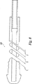
図1及び図2に示すように、筆記具10は主要構成要素として、複数の部品、例えば軸12、カートリッジ40、端栓100及び長手方向軸線A−Aを有する。カートリッジ40は、軸12内へ挿入可能であり、端栓100により軸12内に保持できる。端栓100は、軸12に永続的に結合されたものであってもよく、或いはカートリッジ内の筆記媒体が少なくなったときに交換用カートリッジ40を軸部材12内へ挿入できるよう取り外し可能に取り付けられたものであってもよい(これについては、以下に詳細に説明する)。 カートリッジ要素40は、筆記先端部42、本体44及び近位非筆記端部50を有している。筆記先端部42は、任意所望の形態であってよく、例えば、ローラボール、ボールペンのボール、又はペン先(例えば、フェルトペン又は万年筆のペン先)であってよい。本体44は、筆記媒体リザーバ52を更に有し、このリザーバ52は、筆記媒体を直接又は繊維状詰め物又は綿球の状態で保持するのがよい。他のタイプの筆記先端部及び筆記媒体を本発明の精神及び範囲から逸脱することなく使用できる。例えば、筆記具10は、筆記媒体として鉛筆芯又は蛍光流体を用いてもよい。近位端部50は、選択されたタイプの筆記媒体について筆記中カートリッジ40の適正な動作を可能にするよう筆記媒体リザーバ52の通気を可能にする開口部54を備えるのがよい。しかしながら、これとは異なり、通気を必要としないカートリッジ、例えば加圧カートリッジを用いることができる。
As shown in FIGS. 1 and 2, the writing instrument 10 has a plurality of parts such as a
軸12は、全体として細長く形状が円筒形である。軸12は、遠位筆記端部20、近位非筆記端部30及びキャビティ(空所)14を更に有している。キャビティ14は、カートリッジ40を受け入れるよう形作られている。遠位端部20は、カートリッジ40の筆記先端部42が軸12から突き出ることができるよう形作られた開口部22を有している。近位端部30は、端栓100を受け入れるよう形作られた開口部32を有している。好ましい実施形態では、筆記先端部42の直径は、カートリッジ40の本体44の直径よりも小さく、それにより肩60が形成されている。突起70は、遠位端開口部22に隣接し且つその近位側で軸12に形成され、カートリッジ40の肩60は、突起70に当接することができ、これについては以下に詳細に説明する。
The
図3〜図5に示すように、端栓100は、外側端キャップ110及び内側区分112を有している。内側区分112は、軸12の内側に嵌まるよう形作られると共に好ましくは軸12の近位端開口部32と相互作用するよう形作られている。外側端キャップ110は、軸12の外側輪郭16に一致すると共に筆記具10の見た目の外観を一段とよくするような寸法形状のものであるのがよい。内側区分112が外側端キャップ110と交わるところで端栓100を包囲して締り嵌めバンド114を設けるのがよい。
As shown in FIGS. 3 to 5, the
図3〜図5の実施形態では、端栓100は、緩衝要素120と一体に形成されている。カラー130を緩衝要素120と一体に形成するのがよい。好ましい実施形態では、端栓100、緩衝要素120及びカラー130(もし設けられていれば)は、単一部品として形成される。カラー130は、緩衝要素120の遠位端部124と一体に形成され、緩衝要素120の近位端部126は、内側区分112の遠位端部116と一体に形成されている。カラー130は、形状が環状であるのがよく、好ましくは、カートリッジ40の近位端部30を受け入れるよう形作られた遠位孔132を有する。次に、カートリッジ40を端栓100に結合してこれによって保持するのがよく、それにより振れ又は長手方向軸線A−A線に対する横断方向の運動に対し軸12内で安定化させることができる。好ましい実施形態では、カラー130は、肩136を備え、カートリッジ40の近位端部50が例えば安定化のために肩136に当接することができる。
In the embodiment of FIGS. 3 to 5, the
当該技術分野において周知であるように、カートリッジ40のタイプの中には通気を必要とするものがある。一実施形態では、通気は、筆記先端部42と遠位筆記端開口部22との間の空間を通じて行なわれる。さらに、空気がカートリッジ40の近位端開口部54(図11参照)を通って筆記媒体リザーバ52に通じることができるよう近位孔134をカラー130に設けるのがよく、それにより筆記媒体リザーバ52の十分な通気が行なわれる。本発明の他の実施形態は、通気を行う別の方法を利用してもよく、例えば、開口部を端栓100又は軸12の内部に設けてもよい。さらに別の実施形態は、通気を必要としない場合があり、その一例は、加圧カートリッジを用いる筆記用具である。
As is well known in the art, some types of
好ましい実施形態では、筆記具10は、カートリッジ40を軸近位端開口部32から軸12内へ挿入し、端栓100の内側区分112を軸近位端開口部32内へ挿入して取り付けることにより組み立てられる。カートリッジ40の近位端部50は少なくとも、緩衝要素120又はカラー130に当接する。好ましくは、カートリッジ40の近位端部50は、遠位孔132を通ってカラー130内へ挿入され、それによりカラー130によって保持される。肩136をカラー130の孔132内に設ける場合、カートリッジ40の近位端部50は、孔132内へ挿入されて肩136に当接し、それにより安定化される。好ましい実施形態では、端栓100と軸12は、端栓100を軸12から分離して偶発的に飲み込むことができないように互いに固定される。かくして、端栓100及び軸12は好ましくは、同一材料で作られ、例えば超音波溶接によりこれらを永続的に互いに溶接することができる。締り嵌めバンド114は、超音波剪断溶接を用いて端栓100を軸12に永続的に取り付けることができるよう内側区分112と遠位端開口部17との間に十分な締り嵌め関係をもたらす。
In a preferred embodiment, the writing instrument 10 inserts the
本発明の精神及び範囲から逸脱することなく筆記具10を組み立てる他の方法を利用することができる。例えば、カートリッジ40の近位端部50を当接カラー130により肩136内で安定化させるのではなく、カートリッジ40を圧力嵌め、螺合取付け又は接着剤による取付けによって緩衝要素120で保持してもよい。また、剪断溶接又は他の取付け手段、例えば圧力嵌め、螺合又は接着剤の代わりに表溶接を用いて端栓100を軸12に取り付けてもよい。さらに、軸12への端栓100の取付けは、永続的であってよく、或いは端栓100を軸12から取り外し可能に取り付けてもよい(この場合、端栓100の寸法形状は、飲み込んだとしても結果的に窒息を生じさせないよう選択される)。
Other methods of assembling the writing instrument 10 can be utilized without departing from the spirit and scope of the present invention. For example, rather than stabilizing the
筆記先端部42は、長手方向軸線A−Aに沿って軸方向に軸12内に変位できるよう軸12の筆記端部20を可動的に貫通する。これにより、筆記先端部42は、筆記圧力が筆記先端部42に加えられたりこれから除かれたときにこれに加わる力に応動することができる。かかる力に応答して、緩衝要素120は、カートリッジ40を介して筆記先端部42に付勢力を逆方向にもたらし、筆記具10のユーザに或る特定の感触をもたらす。遠位端開口部22は、長手方向軸線A−Aから外れる筆記先端部42の撓みを阻止するために開口部22及び筆記先端部42の壁相互間の最小隙間を可能にするよう形作られている。さらに、カートリッジ近位端部50は好ましくはカラー130内へ挿入されるので、カートリッジ40の撓み又は振れ(長手方向軸線A−Aに対して横断方向の運動)が一段と阻止される。
The writing
好ましくは、筆記具10は、カートリッジ40の肩60が軸12の突起70に常時圧接するように僅かな予荷重が緩衝要素120に加わるように組み立てられる。したがって、たとえ筆記用具10が使用されていなくても、緩衝要素120は、遠位筆記端部20に向かって長手方向軸線A−Aに沿い軸方向に付勢力をカートリッジ40及び筆記先端部42にもたらす。これは、ユーザが筆記具10の使用中、がたつき感触を受けるのを阻止するのに役立つ。さらに、緩衝要素120に加わるこの予荷重は、カートリッジ40が常時カラー130(好ましくは、肩136)に押し付けられるようにし、それによりカートリッジ40がカラー130から分離しないようになるのを一段と保証する。
Preferably, the writing instrument 10 is assembled such that a slight preload is applied to the
本発明の他の実施形態は、ユーザが緩衝要素120に加わる予荷重の大きさを変えることができるようにしてもよい。例えば、好ましい実施形態では、端栓100を螺合取付けにより軸12に取り付けてもよく、それによりユーザは、端栓100を軸近位端開口部32内へ挿入する量を増減することにより緩衝要素120に加わる予荷重の大きさを増減することができる。端栓100を軸近位端部32内へ挿入すればするほどそれだけ一層緩衝要素120がカートリッジの肩60に圧接している突起70から受ける圧縮度が大きくなる。というのは、突起70と緩衝要素120の遠位端部124との間の距離が短くなるからである。
Other embodiments of the invention may allow the user to change the amount of preload applied to the
好ましい実施形態では、緩衝要素120は、ばねの形態を取るのがよい。注目されることとして、緩衝要素120の幾何学的形状は、緩衝要素120を形成するために用いられる材料及び所望のばね定数で決まる。材料をいったん選択すると共に材料の曲げ弾性率をいったん決定すると、緩衝要素120の幾何学的形状は、緩衝要素120にとって所望のばね定数(ばねが圧縮される力/距離)をもたらすよう定めることができる。したがて、緩衝要素120を構成するために用いられる材料の実際の曲げ弾性率は、本発明にとって必須の要件ではない。厚さを増減すると共にばねコイルの断面形状及び向きを変えることにより、ばね定数を制御することができる。所望のばね定数をもたらすのにどのように緩衝要素120を構成するかについての知識は、当該技術分野において周知である。好ましい実施形態では、材料の剛性及び緩衝要素120のばね形態は、約0.45kg/mmのばね定数をもたらすよう選択される。約0.10kg/mm以上であると共に(或いは)1kg/mm以下であるばね定数が一般に好ましい。しかしながら、本発明の精神及び範囲から逸脱することなく他のばね定数を使用できる。
In a preferred embodiment, the
所望ならば、ばね120′の形態をした緩衝要素120は、図8に示すように可変ばね定数を有するよう更に構成されたものであってよい。かくして、ユーザが緩衝要素120を圧縮しているときのばね定数の変化は、非直線的に増大する(これに対し、標準型のばねは、全体として直線的に増大するばね定数を有する)。当業者に知られた多くの方法のうち任意のものに関し可変ばね定数を達成できる。例えば、隣り合うコイル相互間に様々な距離A,B,Cを有するコイルばねは、可変ばね定数をもたらすことができる。ばねを圧縮すると、コイルは次々に底に突き当たり、互いに密に間隔を置いたコイルで開始する。隣り合うコイルが底に突き当たるたびごとに、コイルばねの総合的なばね定数が増大する。かくして、ユーザが筆記先端部42を増大する力で基材に押し付けると、ばねは、ユーザの加圧力に対して増大した抵抗をもたらす。それにより、ばねの過剰圧縮が妨害され又は回避できる。さらに、圧力の増大は、ユーザに手応えをもたらし、ユーザに筆記先端部42に加える圧力を小さくするよう思い起こさせることができる。
If desired, the dampening
一実施形態では、軸12は、透明な材料で構成され、それにより端栓100の緩衝要素120を見ることができる。これにより、筆記具10の見栄えが向上する。
In one embodiment,
製造及び組立てを単純にすると共に可動部品の数を減少させるために、端栓100と緩衝要素120を射出成形法により一体に形成するのがよい。したがって、かかる実施形態の緩衝要素120は、以下に説明するように射出成形法により形成できるように形作られる。
In order to simplify the manufacturing and assembly and reduce the number of moving parts, the
当該技術分野においては周知のこととして、射出成形法により真に螺旋状のコイルばねを製造することは極めて困難である。形成される輪郭は、複雑過ぎて合わせ面に沿って分離する金型で形成するのは適していない。射出成形法により形成される真に螺旋状のコイルばねは一般に、形状の複雑さに起因してばねを金型から突き出す際に損傷を受ける。例えば、図6に示すように、螺旋コイルばね500は、アンダーカット510を有する。これらアンダーカット510は、螺旋コイルばねが射出成形金型キャビティから容易に取り出されるのを阻止する。
As is well known in the art, it is extremely difficult to produce a truly helical coil spring by injection molding. The contour to be formed is too complex to be formed with a mold that separates along the mating surface. True spiral coil springs formed by injection molding are generally damaged when the springs are ejected from the mold due to the complexity of the shape. For example, as shown in FIG. 6, the
本発明の好ましい実施形態の緩衝要素120は、緩衝要素120が射出成形金型から取り出されるのを阻止するアンダーカットが無いように形成される。図4で分かるように、成形端栓100は、はっきりとした分離平面X−Xを有する。分離平面X−Xに沿う緩衝要素120の各半部は、ばねセグメント122で構成されており、各ばねセグメント122は一般に、好ましくは断面が“D”形状の円環体(トーラス)の半部の形状をしている。緩衝要素120の平面図から分かるように(図3)、真に螺旋状のコイルばねの状態になっているのでばねセグメント122に沿ってアンダーカットが存在しない。緩衝要素120の平面図から、この結果、緩衝要素120にとってジグザグの外観が生じている。
The
端栓100を形成するために使用できる例示の成形装置が、図7に示されている。緩衝要素120付きの端栓100の構成材料を図7に示すように金型半部300,302内へ射出するのがよい。各金型半部300,302は、外側端キャップキャビティ310、内側区分キャビティ312、カラーキャビティ314(カラーを設けた場合)及びばねセグメントキャビティ320を有している。各金型半部のばねセグメントキャビティ320は、互いに繋がっていない。金型半部300,302は、ピンキャビティ352を更に有し、これらピンキャビティ352により、ピン350を金型半部300,302が端栓100の所望の内部形状を維持するために相互に合わされると、金型半部300,302相互間に挿入することができる。
An exemplary molding apparatus that can be used to form
金型半部300,302を合致させると、それぞれの外側端キャップキャビティ310、内側区分キャビティ312及びカラーキャビティ314は、互いに整列し、第1の金型半部300のばねセグメントキャビティ320の各々の端部は、第2の金型半部302の2つの隣り合うばねセグメントキャビティ320の端部と整列する。カラー130に孔132,134及び肩136を形成すると共にばねセグメント122の内側部分を構成するようピン350を挿入する。溶融又は少なくとも流動性の物質を用いられる材料に応じて金型内に注入し、そして冷却させ又は硬化させる。次に、成形された端栓100を金型から取り出す。
When mating mold halves 300, 302, the respective outer
端栓100は、熱可塑性ポリマーであるSAN(スチレンアクリロニトリル)で構成されたものであるのがよい。しかしながら、他の熱可塑性樹脂、例えばABS、スチレン、アセタール、ポリカーボネート又は充填剤入り材料を含む多くの他の材料も又使用できる。端栓100を形成する際に用いられる材料の所望の特性としては、この材料が大量生産方式の製造法、例えば射出成形法に使用できること、並びに曲げ弾性率又は剛性が比較的高いことが挙げられる。好ましくは、この材料の曲げ弾性率は、約100,000psi以上である。この値を下回る曲げ弾性率を有する材料は実用上、柔軟過ぎるので緩衝要素120を形成するために使用することができないことが判明した。さらに、理論的には使用可能な曲げ弾性率に上限は無いが、約500,000psiの曲げ弾性率は一般に、大抵の熱可塑性ポリマーにおいて見受けられる上限であることが注目される。
端栓100を製造する他の方法としては、立体リソグラフィー又はブランク成形品の機械加工の利用が挙げられる。
The
Other methods for manufacturing the
別の好ましい実施形態では、緩衝要素120は、図9及び図10に示す移動制限突起400を更に有し、これら移動制限突起は、緩衝要素120が引き受けることができる圧縮の量を制限する。移動制限突起400は、特に緩衝要素120が永久歪を起こす場合があり又はこれとは異なる風に変形可能な材料(例えばプラスチック)で形成されている場合、緩衝要素120の破断又は望ましくない永久変形の原因となる場合のある緩衝要素120の過剰圧縮を阻止する。各移動制限突起400は、遠位端部402及び近位端部404を有している。遠位端部402は好ましくは、僅かに凹状であり、近位端部404は好ましくは、僅かに凸状である(但し、その逆の形態も可能であると共にいずれか一方の端部のところを他の形態にしてもよく又は曲率を設けなくてもよい)。緩衝要素120を或る長さまでいったん圧縮すると、各移動制限突起400の遠位端部402は、隣りの移動制限突起400の近位端部404に当接し、緩衝要素120がそれ以上圧縮されるのを阻止する。この実施形態も又、移動制限突起キャビティを金型半部300,302に付け足した状態で上述の射出成形法を用いて形成できる。
In another preferred embodiment, the
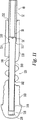
変形例として、緩衝要素の底突き当たりを妨げ又は阻止するために、停止要素500を設けてもよい。停止要素500は好ましくは、緩衝要素とは別個に形成される。図11及び図12の例示の実施形態では、停止要素500は、緩衝要素120、端ボタン100及びカラー130をそれぞれ貫通して設けられた長手方向チャネル502,504,506を貫通して延びる停止ピンの形態をしている。停止要素500は好ましくは、遠位端部512のに、カートリッジ40の近位端部52に当接するよう寸法決めされた拡径端部又はヘッド510を有する。拡径端部510も又、後で明らかになる理由で、停止要素500を長手方向チャネル502,504,506中に挿入できる距離を制限するためにカラー130内の肩514に当接するよう形作られたものであるのがよい。停止要素500は、停止要素500が緩衝要素120の圧縮の始めに緩衝要素120の圧縮に影響を及ぼさないように構成されている。しかしながら、緩衝要素120を所定量圧縮すると、停止要素500は、有効になり、緩衝要素120のそれ以上の圧縮を妨げ又は阻止する。
As a variant, a
図11及び図12の実施形態では、停止要素500は、緩衝要素120が非圧縮状態にあるときに緩衝要素120よりも効果的に短いことにより緩衝要素120の所定量の圧縮後にのみ有効である。かくして、緩衝要素120の長さが短くなって停止要素500の長さに実質的に等しくなると、停止要素500は、緩衝要素120のそれ以上の圧縮に影響を及ぼすことができる。かくして、停止要素500と緩衝要素120の長さの差は、緩衝要素120が停止要素500によって影響を受け又は作用を受ける前に有効な持続時間又は度合いを定める。長さの差は、当業者に知られている多くの要因、例えば緩衝要素120のばね定数、材料及び(又は)形態に基づいて選択される。停止要素500が緩衝要素120の機能に影響を及ぼす程度又は度合いは、ユーザの主観的な好みに基づいて決定できる。かくして、極めて僅かな緩衝作用を持つ筆記具10が望ましい場合、停止要素500を緩衝要素120の圧縮後緩衝要素120に非常に迅速に影響を及ぼすよう形成するのがよい。図11及び図12の実施形態を参照すると、極めて僅かな緩衝作用を達するため、停止要素500と緩衝要素120の長さの差は、最小限である。停止要素500が緩衝要素120の機能に影響を及ぼす度合い又は程度を決定する際のもう1つの要因は、ばねの降伏点である場合がある。特に、停止要素500は、緩衝要素120の降伏点を越えないようにするよう緩衝要素120と相互作用するよう選択されると共に構成されたものであるのがよい。
In the embodiment of FIGS. 11 and 12, the
図11及び図12の実施形態では、停止要素500の作動は、緩衝要素120が非圧縮、中立、休息位置にあるとき(即ち、カートリッジ40を基材に押し付けることによって作動されていないとき)、停止要素500の近位端部518とカラー130内のチャネル506の閉鎖端520との間において端ボタン100中に隙間516を空けることにより達成される。停止要素500の拡径端部510は、緩衝要素120が作動されていないとき(即ち、圧縮されていないとき)、上述したように肩514に当接して近位端部518がチャネル506の閉鎖端520に当接するのを阻止する。隙間516により、緩衝要素120が停止要素500の長さまで圧縮される前に所与の程度の緩衝要素120の圧縮が可能になる。緩衝要素120を所定の程度いったん圧縮すると、停止要素500の近位端部518は、カラー130内のチャネル506の閉鎖端520に接触して緩衝要素120のそれ以上の圧縮を妨害し又は阻止する。
In the embodiment of FIGS. 11 and 12, actuation of the
緩衝要素120、停止要素500及び隙間514の寸法形状並びに材料は、底に突き当たる前(即ち、緩衝要素120の圧縮性が停止要素500によって影響を受ける前)における緩衝要素120の所望範囲の圧縮性を達成するよう選択される。一実施形態では、隙間516は、長さが約1mmである。隙間516の長さの選択により停止要素500が緩衝要素120の機能に影響を及ぼす度合い又は程度が影響を受けるので、かかる選択は、ユーザの好み及び(又は)一般に緩衝要素120に対する停止要素500の影響の決定に関して上述したような工学的特徴に基づくのがよい。停止要素500を比較的硬質の材料で作る場合、停止要素500の近位端部518がチャネル506の閉鎖端520にいったん接触すると、緩衝要素120のそれ以上の圧縮が本質的に阻止される。しかしながら、停止要素500の近位端部518がチャネル506の閉鎖端520に接触した後でも緩衝要素120のそれ以上の圧縮が可能になるように停止要素500を或る程度の弾性を持つ材料で作ってもよい。例えば、停止要素500を弾性又は圧縮性或いはエラストマー又はエラストマー様材料、例えばゴム又は熱可塑性エラストマー又はフォームで作ることができる。当然のことながら、停止要素500がいったん有効になると極僅かなそれ以上の圧縮が望ましい場合、停止要素500を非弾性又は非エラストマー材料、例えば鉄系材料又はセラミック材料で作るのがよい。
The dimensions and materials of the
上述したように、筆記媒体リザーバ52の近位端部50は、筆記媒体リザーバ52のための通気を可能にする開口部54を備えるのがよい。かくして、筆記媒体リザーバ52の近位端部50が停止要素500に当接する場合、停止要素500は好ましくは、同様に通気を可能にするよう構成される。図12に示すように、平坦部520を停止要素500の拡径端部510に形成するのがよい。かくして、筆記媒体リザーバ52の通気も又、停止要素500を通して起こることが可能である。
As described above, the
本発明の一特徴によれば、本明細書において説明した例示の筆記具では、緩衝要素120と端栓100は好ましくは、互いに一体に形成されている。緩衝要素120と一体に形成される端栓100の形成中、これらのうち少なくとも一方は、成形可能な材料で作られる。かくして、緩衝要素120及び端栓100は、形成方法がいったん完了すると、分離できずに一要素として働き、筆記具の組立ての際に使用する前においては互いにそれ以上の組立て又は取付けは不要である。
According to one aspect of the invention, in the example writing instrument described herein, the
或る場合には、緩衝要素を端栓の材料とは異なる材料で形成することが望ましい場合がある。本発明は、一体に形成された緩衝要素を備えた端栓を形成することにより実施でき、この場合、緩衝要素は、端栓の材料とは異なる材料で作られる。例えば、別の好ましい実施形態では、2材質成形法(例えば「ツーショット(two-shot)」法又は「複合成形(overmolding)」法)により端栓100を熱可塑性樹脂、例えばSANで形成し、緩衝要素120をこれとはことなる成形材料で形成することができる。なお、上述の成形方法の両方は、当該技術分野において周知である。また、緩衝要素120を成形できない材料、例えば金属で作り、そしてインサート成形法又は複合成形法により端栓100と一体に形成してもよい。端栓100及び緩衝要素120の形成後においては、端栓100及び緩衝要素120は、分離不能であって一要素として働き、筆記具の組立ての際に使用する前においては互いにそれ以上の組立て又は取付けは不要である。別の好ましい実施形態では、端栓100を成形できない材料で作り、そして成形可能な材料で作られている緩衝要素120と一体に形成する。
In some cases, it may be desirable to form the cushioning element from a different material than the material of the end plug. The present invention can be practiced by forming an end plug with an integrally formed buffer element, wherein the buffer element is made of a material different from the material of the end plug. For example, in another preferred embodiment, the
本発明の精神及び範囲から逸脱することなく他の追加の特徴を筆記具10に追加することができる。例えば、好ましい実施形態では、ユーザが筆記具10を掴むのを助ける掴み要素210が軸12に追加される。また、使用していないときに遠位筆記端部22及び筆記先端部42を覆うキャップ220を設けるのがよい。しかしながら、かかる追加の特徴は、望ましいが、本発明の実施にとって必要ではない。
Other additional features can be added to the writing instrument 10 without departing from the spirit and scope of the present invention. For example, in a preferred embodiment, a
本発明は、上述した好ましい実施形態及び組立て手段にのみ限定されるものではない。例えば、本発明の緩衝要素を上記の好ましい実施形態において説明したように端栓100ではなく、筆記具10の別の要素、例えば軸12又は前側ノーズコーンと一体形成してもよい。本発明の他の実施形態は、上記の好ましい実施形態において説明したように圧縮されるのではなく、筆記中引き伸ばされる緩衝要素を用いてもよい。もう1つの例として、筆記具10の他の実施形態を、例えば着脱自在な前側ノーズコーンを備えた実施形態に関し、カートリッジ40を軸12の遠位端部20中へ挿入することにより組み立てることができる。
The present invention is not limited to the preferred embodiments and assembly means described above. For example, the cushioning element of the present invention may be integrally formed with another element of the writing instrument 10, such as the
これらの特徴は各々少なくとも単独で本発明にとって望ましい又は本発明にとって必要不可欠ではない独特の利点を持つ本発明の別個且つ独立の特徴であることは理解されよう。また、一実施形態に関して説明した特徴を明示しているかどうかとは関係なく別の実施形態に利用できることは理解されよう。本明細書において説明した種々の特徴を単独で又はこれらの任意の組み合わせで利用することができる。したがって、本発明は、本明細書において具体的に説明した実施形態にのみ限定されるものではない。 It will be understood that each of these features is a separate and independent feature of the present invention with unique advantages that are each at least alone, desirable or not essential to the present invention. It will also be appreciated that other embodiments may be used regardless of whether the features described with respect to one embodiment are explicitly indicated. The various features described herein can be utilized alone or in any combination thereof. Accordingly, the present invention is not limited to the embodiments specifically described herein.
上記説明及び図面は、本発明の好ましい実施形態を記載しているが、特許請求の範囲に記載された本発明の精神及び範囲から逸脱することなくその種々の追加例、改造例及び置換例を想到できることは理解されよう。特に、当業者には明らかなように、本発明をその精神又は本質的な特徴から逸脱することなく、他の特定の形態、構造、配列、比率で及び他の要素、材料及び部品を備えた状態で実施できる。当業者であれば、本発明は、本発明の原理から逸脱することなく、特定の環境及び使用上の要件に適合した本発明の実施に用いられる構造、配列、比率、材料及び部品等について多くの改造を施して利用できることは理解されよう。したがって、本願において開示した実施形態は、あらゆる点で例示であって本発明を制限するものではなく、本発明の範囲は、特許請求の範囲の記載に基づいて定められ、上記説明には限定されない。 While the above description and drawings describe preferred embodiments of the present invention, various additions, modifications and substitutions thereof may be made without departing from the spirit and scope of the invention as set forth in the claims. It will be understood that this is possible. In particular, it will be apparent to those skilled in the art that the present invention is provided with other specific forms, structures, arrangements, ratios and other elements, materials and components without departing from the spirit or essential characteristics thereof. Can be implemented in the state. Those skilled in the art will appreciate that the present invention is numerous in terms of structures, arrangements, ratios, materials, components, etc. used in the practice of the present invention adapted to specific environmental and usage requirements without departing from the principles of the present invention. It will be understood that it can be used with modification of. Accordingly, the embodiments disclosed in the present application are illustrative in all respects and do not limit the present invention, and the scope of the present invention is defined based on the description of the scope of claims and is not limited to the above description. .
Claims (12)
近位開口部を備えた近位端部、及び、前記近位端部と反対側の筆記端開口部を備えた遠位端部を有する軸と、
前記軸に位置決めされ、前記筆記端開口部から延びる筆記先端部と、近位端部とを備える筆記媒体カートリッジと、
前記近位開口部に設けられた端栓と、
前記端栓と一体に、単一部品として形成された緩衝要素とを有し、
前記緩衝要素は、前記筆記媒体カートリッジの前記近位端部に当接し、
前記端栓が、前記緩衝要素に加わる予荷重の大きさを変えるための調整可能な螺合取付け部によって前記軸の前記近位開口部に取り付けられ、
前記緩衝要素を貫通して延びる停止要素を有し、前記停止要素は、前記緩衝要素を所定の度合いまでいったん圧縮すると前記端栓に当接するとともに、前記停止要素は、前記端栓に当接した後の前記緩衝要素の更なる圧縮を可能にする弾性材料で構成される、
筆記具。A writing instrument,
A shaft having a proximal end with a proximal opening and a distal end with a writing end opening opposite the proximal end;
A writing medium cartridge comprising a writing tip positioned on the shaft and extending from the writing end opening; and a proximal end;
An end plug provided in the proximal opening;
A cushioning element formed as a single piece integrally with the end plug;
The buffer element abuts the proximal end of the writing media cartridge;
The end plug is attached to the proximal opening of the shaft by an adjustable threaded attachment for changing the amount of preload applied to the cushioning element ;
A stop element extending through the buffer element, wherein the stop element contacts the end plug once the buffer element is compressed to a predetermined degree, and the stop element contacts the end plug; Composed of an elastic material that allows further compression of the cushioning element afterwards,
Writing instrument.
近位開口部を備えた近位端部、及び、前記近位端部と反対側の筆記端開口部を備えた遠位端部を有する軸と、
前記軸に位置決めされ、前記筆記端開口部から延びる筆記先端部と、近位端部とを備える筆記媒体カートリッジと、
前記近位開口部に設けられた端栓と、
前記端栓と一体に、単一部品として形成された緩衝要素とを有し、
前記緩衝要素は、前記筆記媒体カートリッジの前記近位端部に当接し、
前記端栓が、前記近位開口部に超音波溶接され、
前記緩衝要素を貫通して延びる停止要素を有し、前記停止要素は、前記緩衝要素を所定の度合いまでいったん圧縮すると前記端栓に当接するとともに、前記停止要素は、前記端栓に当接した後の前記緩衝要素の更なる圧縮を可能にする弾性材料で構成される、
筆記具。A writing instrument,
A shaft having a proximal end with a proximal opening and a distal end with a writing end opening opposite the proximal end;
A writing medium cartridge comprising a writing tip positioned on the shaft and extending from the writing end opening; and a proximal end;
An end plug provided in the proximal opening;
A cushioning element formed as a single piece integrally with the end plug;
The buffer element abuts the proximal end of the writing media cartridge;
The end plug is ultrasonically welded to the proximal opening ;
A stop element extending through the buffer element, wherein the stop element contacts the end plug once the buffer element is compressed to a predetermined degree, and the stop element contacts the end plug; Composed of an elastic material that allows further compression of the cushioning element later
Writing instrument.
近位開口部を備えた近位端部及び筆記端開口部を備えた遠位端部を有する軸と、
前記軸内に設けられ、前記筆記端開口部から出ている筆記先端部を備えたカートリッジと、
前記近位開口部内に設けられた端栓と、
前記端栓と一体に形成された緩衝要素とを有し、
前記カートリッジは、前記緩衝要素によって保持され、
前記緩衝要素は、前記端栓の材料とは異なる材料で構成され、
前記緩衝要素を貫通して延びる停止要素を有し、前記停止要素は、前記緩衝要素を所定の度合いまでいったん圧縮すると前記端栓に当接するとともに、前記停止要素は、前記端栓に当接した後の前記緩衝要素の更なる圧縮を可能にする弾性材料で構成される、
筆記具。A writing instrument,
A shaft having a proximal end with a proximal opening and a distal end with a writing end opening;
A cartridge provided with a writing tip provided in the shaft and protruding from the writing end opening;
An end plug provided in the proximal opening;
A buffer element integrally formed with the end plug;
The cartridge is held by the buffer element;
The buffer element is made of a material different from the material of the end plug ;
A stop element extending through the buffer element, wherein the stop element contacts the end plug once the buffer element is compressed to a predetermined degree, and the stop element contacts the end plug; Composed of an elastic material that allows further compression of the cushioning element later
Writing instrument.
近位端部及び筆記端開口部を備えた遠位端部を有する軸を有し、
前記軸に位置決めされ、前記筆記端開口部から出ている筆記先端部及び近位端部を備えたカートリッジを有し、
近位開口部が、前記軸の前記近位端部に形成され、
前記筆記具は、前記軸の前記近位開口部に位置決めされた端ボタンを更に有し、
前記カートリッジに当接するコイルばねの形態をした緩衝要素を有し、前記緩衝要素は、筆記中の前記カートリッジによる前記緩衝要素の圧縮時に前記軸内での前記カートリッジの軸方向運動を可能にし、
前記緩衝要素を貫通して延びる停止要素を有し、前記停止要素は、前記緩衝要素を前記カートリッジの所定の度合いにわたりいったん圧縮すると前記端ボタンに当接するとともに、前記停止要素は、前記端ボタンに当接した後の前記緩衝要素の更なる圧縮を可能にする弾性材料で構成され、前記カートリッジの前記近位端部は、前記停止要素に当接する、筆記具。A writing instrument,
A shaft having a distal end with a proximal end and a writing end opening;
Having a cartridge positioned on the shaft and having a writing tip and a proximal end protruding from the writing end opening;
A proximal opening is formed at the proximal end of the shaft;
The writing instrument further comprises an end button positioned in the proximal opening of the shaft;
A cushioning element in the form of a coil spring that abuts the cartridge, the cushioning element allowing axial movement of the cartridge within the shaft when the cushioning element is compressed by the cartridge during writing;
A stop element extending through the buffer element, the stop element abutting the end button once the buffer element is compressed over a predetermined degree of the cartridge, and the stop element is attached to the end button; A writing instrument comprised of an elastic material that allows further compression of the cushioning element after abutment , wherein the proximal end of the cartridge abuts the stop element.
前記停止要素は、前記端ボタンの前記長手方向チャネルを貫通して延び、
前記緩衝要素が非圧縮位置にあるとき、隙間が、前記停止要素と前記端ボタンの前記長手方向チャネルの前記閉鎖近位端との間に空けられる、請求項8記載の筆記具。A longitudinal channel is formed in the end button, the longitudinal channel having a closed proximal end;
The stop element extends through the longitudinal channel of the end button ;
9. The writing instrument of claim 8 , wherein a gap is opened between the stop element and the closed proximal end of the longitudinal channel of the end button when the cushioning element is in an uncompressed position.
近位端部及び筆記端開口部を備えた遠位端部を有する軸を有し、
前記軸に位置決めされ、前記筆記端開口部から出ている筆記先端部及び近位端部を備えたカートリッジを有し、
近位開口部が、前記軸の前記近位端部に形成され、
前記筆記具は、前記軸の前記近位開口部に位置決めされた端ボタンを更に有し、
前記カートリッジに当接するコイルばねの形態をした緩衝要素を有し、前記緩衝要素は、筆記中の前記カートリッジによる前記緩衝要素の圧縮時に前記軸内での前記カートリッジの軸方向運動を可能にし、
前記緩衝要素を貫通して延びる停止要素を有し、前記停止要素は、前記緩衝要素を前記カートリッジの所定の度合いにわたりいったん圧縮すると前記端ボタンに当接するとともに、前記停止要素は、前記端ボタンに当接した後の前記緩衝要素の更なる圧縮を可能にする弾性材料で構成され、
長手方向チャネルが、前記端ボタンに形成され、前記長手方向チャネルは、閉鎖された近位端を有し、
前記停止要素は、前記端ボタンの前記長手方向チャネルを貫通して延び、
前記緩衝要素は、前記端ボタンと前記カートリッジの前記近位端部との間に位置決めされ、
隙間が、前記停止要素と前記長手方向チャネルの前記閉鎖近位端との間に空けられる、筆記具。A writing instrument,
A shaft having a distal end with a proximal end and a writing end opening;
Having a cartridge positioned on the shaft and having a writing tip and a proximal end protruding from the writing end opening;
A proximal opening is formed at the proximal end of the shaft;
The writing instrument further comprises an end button positioned in the proximal opening of the shaft;
A cushioning element in the form of a coil spring that abuts the cartridge, the cushioning element allowing axial movement of the cartridge within the shaft when the cushioning element is compressed by the cartridge during writing;
A stop element extending through the buffer element, the stop element abutting the end button once the buffer element is compressed over a predetermined degree of the cartridge, and the stop element is attached to the end button; Composed of an elastic material that allows further compression of the cushioning element after abutment,
A longitudinal channel is formed in the end button, the longitudinal channel having a closed proximal end;
The stop element extends through the longitudinal channel of the end button ;
The cushioning element is positioned between the end button and the proximal end of the cartridge;
A writing instrument, wherein a gap is opened between the stop element and the closed proximal end of the longitudinal channel.
近位端部及び筆記端開口部を備えた遠位端部を有する軸を有し、
前記軸に位置決めされ、前記筆記端開口部から出ている筆記先端部及び近位端部を備えたカートリッジを有し、
近位開口部が、前記軸の前記近位端部に形成され、
前記筆記具は、前記軸の前記近位開口部に位置決めされた端ボタンを更に有し、
前記カートリッジに当接するコイルばねの形態をした緩衝要素を有し、前記緩衝要素は、筆記中の前記カートリッジによる前記緩衝要素の圧縮時に前記軸内での前記カートリッジの軸方向運動を可能にし、
前記緩衝要素を貫通して延びる停止要素を有し、前記停止要素は、前記緩衝要素を前記カートリッジの所定の度合いにわたりいったん圧縮すると前記端ボタンに当接するとともに、前記停止要素は、前記端ボタンに当接した後の前記緩衝要素の更なる圧縮を可能にする弾性材料で構成される、筆記具。A writing instrument,
A shaft having a distal end with a proximal end and a writing end opening;
Having a cartridge positioned on the shaft and having a writing tip and a proximal end protruding from the writing end opening;
A proximal opening is formed at the proximal end of the shaft;
The writing instrument further comprises an end button positioned in the proximal opening of the shaft;
A cushioning element in the form of a coil spring that abuts the cartridge, the cushioning element allowing axial movement of the cartridge within the shaft when the cushioning element is compressed by the cartridge during writing;
A stop element extending through the buffer element, the stop element abutting the end button once the buffer element is compressed over a predetermined degree of the cartridge, and the stop element is attached to the end button; Writing instrument comprised of an elastic material that allows further compression of the cushioning element after abutment .
Applications Claiming Priority (3)
| Application Number | Priority Date | Filing Date | Title |
|---|---|---|---|
| US38930003A | 2003-03-14 | 2003-03-14 | |
| US10/389,300 | 2003-03-14 | ||
| PCT/US2004/007744 WO2004082963A1 (en) | 2003-03-14 | 2004-03-12 | Writing instrument with cushioning element |
Publications (3)
| Publication Number | Publication Date |
|---|---|
| JP2006520281A JP2006520281A (en) | 2006-09-07 |
| JP2006520281A5 JP2006520281A5 (en) | 2007-04-26 |
| JP4733016B2 true JP4733016B2 (en) | 2011-07-27 |
Family
ID=33029659
Family Applications (1)
| Application Number | Title | Priority Date | Filing Date |
|---|---|---|---|
| JP2006507156A Expired - Fee Related JP4733016B2 (en) | 2003-03-14 | 2004-03-12 | Writing instrument with cushioning element |
Country Status (15)
| Country | Link |
|---|---|
| US (1) | US7137751B2 (en) |
| EP (1) | EP1606123B1 (en) |
| JP (1) | JP4733016B2 (en) |
| KR (1) | KR20050115914A (en) |
| CN (1) | CN1784315B (en) |
| AR (1) | AR046800A1 (en) |
| AU (1) | AU2004221894B2 (en) |
| BR (1) | BRPI0408324B1 (en) |
| CA (1) | CA2519530C (en) |
| MX (1) | MXPA05009761A (en) |
| MY (1) | MY143893A (en) |
| RU (1) | RU2337834C2 (en) |
| TW (1) | TWI324565B (en) |
| WO (1) | WO2004082963A1 (en) |
| ZA (1) | ZA200507568B (en) |
Families Citing this family (15)
| Publication number | Priority date | Publication date | Assignee | Title |
|---|---|---|---|---|
| DE202005005043U1 (en) * | 2005-03-30 | 2006-08-10 | Schwan-Stabilo Cosmetics Gmbh & Co. Kg | applicator |
| MX2009000230A (en) * | 2006-07-07 | 2009-04-07 | Bic Soc | Writing instrument with cushioning device. |
| JP4716377B2 (en) * | 2007-01-23 | 2011-07-06 | 三菱鉛筆株式会社 | Writing instrument |
| US7959368B2 (en) * | 2008-01-29 | 2011-06-14 | Rong-Lin Sheu | Ink cartridge structure for pens |
| FR2936739B1 (en) * | 2008-10-03 | 2013-03-22 | Bic Soc | WRITING INSTRUMENT COMPRISING A VERTICALLY EMITTED END ORGAN. |
| JP5608015B2 (en) * | 2009-09-01 | 2014-10-15 | 三菱鉛筆株式会社 | Applicator with valve |
| EP2388152B1 (en) | 2010-05-20 | 2018-07-11 | Parker Pen Products | Writing instrument and ink cartridge unit |
| JP2016505419A (en) | 2012-12-06 | 2016-02-25 | ヨーロッパ・ブランズ・エス・アーエール・エルEurope Brands S.Ar.L. | Refill plug release assembly and writing instrument including the same |
| USD873917S1 (en) * | 2015-07-10 | 2020-01-28 | Societe Bic | Writing instrument |
| USD780266S1 (en) * | 2015-10-01 | 2017-02-28 | Maped | Writing implement |
| USD798387S1 (en) | 2016-01-04 | 2017-09-26 | National Pen Co., Llc | Writing implement |
| CN105751742A (en) * | 2016-02-16 | 2016-07-13 | 衡宏志 | Manufacturing method of flexible ballpoint pen |
| US10936092B1 (en) * | 2017-02-28 | 2021-03-02 | Apple Inc. | Force-sensing structures for an electronic device |
| CN107878067B (en) * | 2017-11-23 | 2024-02-09 | 攀枝花学院 | Hydraulic elastic pen cap |
| US20200361230A1 (en) * | 2019-05-14 | 2020-11-19 | Kotobuki & Co., Ltd. | Writing instrument and method for manufacturing writing instrument |
Citations (6)
| Publication number | Priority date | Publication date | Assignee | Title |
|---|---|---|---|---|
| JPS51108731A (en) * | 1975-03-20 | 1976-09-27 | Sony Corp | KARAATEREBIJUZOKI |
| JPS5510789A (en) * | 1978-03-31 | 1980-01-25 | Pechiney Aluminium | Methdo of manufacturing electric contact |
| JPS57132584A (en) * | 1980-12-24 | 1982-08-16 | Allied Chem | Device and method of treating liquid |
| JPS63148476A (en) * | 1986-12-10 | 1988-06-21 | Fujitsu Ltd | Head positioning control system for magnetic disk device |
| JPH11157272A (en) * | 1997-11-28 | 1999-06-15 | Sony Corp | Writing utensil |
| JP2000158871A (en) * | 1998-11-24 | 2000-06-13 | Masaaki Fukami | Ball-point pen |
Family Cites Families (31)
| Publication number | Priority date | Publication date | Assignee | Title |
|---|---|---|---|---|
| US1041926A (en) | 1910-04-28 | 1912-10-22 | Josef Werner | Pencil-case. |
| US1043793A (en) | 1911-10-02 | 1912-11-12 | Internat Monorail Co | Truck for monorailway-cars. |
| US1340331A (en) | 1916-12-27 | 1920-05-18 | Frank J Kristofek | Pencil |
| US1508170A (en) | 1922-09-12 | 1924-09-09 | Olier Francis W D | Pencil |
| US1769572A (en) | 1929-02-15 | 1930-07-01 | Grosz Edward | Pencil |
| US1780405A (en) | 1929-12-16 | 1930-11-04 | Percy A Sharrow | Pencil |
| US2055316A (en) | 1935-09-26 | 1936-09-22 | Percy A Sharrow | Pencil |
| US2128456A (en) | 1937-01-02 | 1938-08-30 | Sr Ward A Dusenbury | Fountain pen |
| US2162914A (en) | 1937-12-11 | 1939-06-20 | N And F Corp | Pencil holder |
| US2362582A (en) | 1944-03-09 | 1944-11-14 | Willie T Pearson | Stylus holder |
| US2488179A (en) | 1946-05-28 | 1949-11-15 | Jr John A Engel | Cushioned pencil point |
| US2946311A (en) | 1954-12-01 | 1960-07-26 | Burnie J Craig | Writing instrument |
| US3144005A (en) * | 1960-04-14 | 1964-08-11 | Frank T Johmann | Retraction-protraction mechanism for writing instruments |
| US3192904A (en) * | 1961-11-09 | 1965-07-06 | Frank T Johmann | Writing instrument |
| US3232278A (en) * | 1964-04-20 | 1966-02-01 | Frank T Johmann | Writing instrument |
| DE1461332A1 (en) * | 1964-06-01 | 1968-12-12 | Bross Dipl Ing Helmut | Writing device, in particular ballpoint pen with one or more writing material carriers |
| US3419336A (en) | 1966-07-18 | 1968-12-31 | Norbert A. Kirk | Ball point pens |
| JPS58171392U (en) | 1982-05-10 | 1983-11-16 | 株式会社寿 | Shape pencil |
| US4728474A (en) | 1982-09-28 | 1988-03-01 | Plough, Inc. | Method for making a plastic spring |
| US5257762A (en) | 1990-08-20 | 1993-11-02 | Everbrite, Inc. | Neon tube support having molded spring and method of making the support |
| DE4101635A1 (en) | 1991-01-21 | 1992-07-23 | Michael Seissler | Writing implement with exchangeable cartridge - which has moving mechanism with arrester and spring affecting arrester action |
| JP2531752Y2 (en) | 1991-10-29 | 1997-04-09 | 株式会社サクラクレパス | Applicator |
| US5415487A (en) | 1993-06-08 | 1995-05-16 | Bic Corporation | Vented plug for ink cartridges |
| CN2180474Y (en) * | 1994-01-27 | 1994-10-26 | 董素莲 | Exteudible brush pen |
| JPH09272293A (en) | 1996-02-09 | 1997-10-21 | Kotobuki:Kk | Writing instrument |
| FR2760607B1 (en) | 1997-03-11 | 1999-04-23 | Oreal | DISTRIBUTOR FOR A DELITABLE PRODUCT |
| US5915870A (en) | 1997-11-19 | 1999-06-29 | Bic Corporation | Writing instrument with cartridge spacing element |
| FR2780865B1 (en) | 1998-07-10 | 2000-09-22 | Oreal | DEVICE FOR PACKAGING A PRODUCT IN THE FORM OF A GRAPE EQUIPPED WITH AN OVERPRESSURE ABSORBING MECHANISM |
| CN2380395Y (en) * | 1999-04-18 | 2000-05-31 | 冯培光 | Core-tube ink-suction type clean fountain pen |
| US6261015B1 (en) | 2000-01-28 | 2001-07-17 | Bic Corporation | Roller ball pen with adjustable spring tension |
| US6257787B1 (en) | 2000-06-28 | 2001-07-10 | Norbert Kirk | Ball point pen smooth touch |
-
2004
- 2004-03-11 US US10/800,402 patent/US7137751B2/en not_active Expired - Lifetime
- 2004-03-12 MX MXPA05009761A patent/MXPA05009761A/en active IP Right Grant
- 2004-03-12 AU AU2004221894A patent/AU2004221894B2/en not_active Ceased
- 2004-03-12 CN CN2004800126748A patent/CN1784315B/en not_active Expired - Lifetime
- 2004-03-12 BR BRPI0408324-5A patent/BRPI0408324B1/en not_active IP Right Cessation
- 2004-03-12 JP JP2006507156A patent/JP4733016B2/en not_active Expired - Fee Related
- 2004-03-12 WO PCT/US2004/007744 patent/WO2004082963A1/en active Application Filing
- 2004-03-12 CA CA2519530A patent/CA2519530C/en not_active Expired - Fee Related
- 2004-03-12 KR KR1020057017209A patent/KR20050115914A/en not_active Application Discontinuation
- 2004-03-12 EP EP04720482.1A patent/EP1606123B1/en not_active Expired - Lifetime
- 2004-03-12 ZA ZA200507568A patent/ZA200507568B/en unknown
- 2004-03-12 RU RU2005131844/12A patent/RU2337834C2/en not_active IP Right Cessation
- 2004-03-15 TW TW093106845A patent/TWI324565B/en not_active IP Right Cessation
- 2004-03-15 AR ARP040100858A patent/AR046800A1/en unknown
- 2004-03-15 MY MYPI20040899A patent/MY143893A/en unknown
Patent Citations (6)
| Publication number | Priority date | Publication date | Assignee | Title |
|---|---|---|---|---|
| JPS51108731A (en) * | 1975-03-20 | 1976-09-27 | Sony Corp | KARAATEREBIJUZOKI |
| JPS5510789A (en) * | 1978-03-31 | 1980-01-25 | Pechiney Aluminium | Methdo of manufacturing electric contact |
| JPS57132584A (en) * | 1980-12-24 | 1982-08-16 | Allied Chem | Device and method of treating liquid |
| JPS63148476A (en) * | 1986-12-10 | 1988-06-21 | Fujitsu Ltd | Head positioning control system for magnetic disk device |
| JPH11157272A (en) * | 1997-11-28 | 1999-06-15 | Sony Corp | Writing utensil |
| JP2000158871A (en) * | 1998-11-24 | 2000-06-13 | Masaaki Fukami | Ball-point pen |
Also Published As
| Publication number | Publication date |
|---|---|
| EP1606123A4 (en) | 2010-06-23 |
| CN1784315A (en) | 2006-06-07 |
| CA2519530A1 (en) | 2004-09-30 |
| AR046800A1 (en) | 2005-12-28 |
| WO2004082963A1 (en) | 2004-09-30 |
| MXPA05009761A (en) | 2005-11-17 |
| US7137751B2 (en) | 2006-11-21 |
| KR20050115914A (en) | 2005-12-08 |
| TWI324565B (en) | 2010-05-11 |
| RU2005131844A (en) | 2006-04-27 |
| US20040234322A1 (en) | 2004-11-25 |
| MY143893A (en) | 2011-07-29 |
| AU2004221894B2 (en) | 2010-04-22 |
| CN1784315B (en) | 2012-05-02 |
| CA2519530C (en) | 2012-06-12 |
| TW200510189A (en) | 2005-03-16 |
| RU2337834C2 (en) | 2008-11-10 |
| BRPI0408324B1 (en) | 2014-08-05 |
| AU2004221894A1 (en) | 2004-09-30 |
| EP1606123A1 (en) | 2005-12-21 |
| WO2004082963B1 (en) | 2005-02-17 |
| BRPI0408324A (en) | 2006-03-07 |
| EP1606123B1 (en) | 2014-05-07 |
| ZA200507568B (en) | 2006-11-29 |
| JP2006520281A (en) | 2006-09-07 |
Similar Documents
| Publication | Publication Date | Title |
|---|---|---|
| JP4733016B2 (en) | Writing instrument with cushioning element | |
| JP6595819B2 (en) | Writing instrument | |
| JP7454718B2 (en) | writing implements | |
| KR100434620B1 (en) | Writing utensil and method of manufacturing it | |
| JP3817719B2 (en) | Writing instrument grip | |
| JP2014205242A (en) | Writing instrument | |
| JP6159559B2 (en) | Writing instrument | |
| JP6157906B2 (en) | Writing instrument | |
| JP3756563B2 (en) | Writing instrument grip | |
| JP7202126B2 (en) | writing instrument | |
| JP6715564B2 (en) | Knock type writing instrument | |
| JP6242067B2 (en) | Writing instrument | |
| JP4209383B2 (en) | Writing instrument | |
| WO2018097243A1 (en) | Ballpoint pen | |
| WO2014168195A1 (en) | Writing implement | |
| JP2021045978A5 (en) | ||
| JP6286892B2 (en) | Shaft cylinder provided with an elastic member | |
| WO2014168196A1 (en) | Writing implement | |
| JPH10181281A (en) | Writing implement | |
| JP2000238485A (en) | Board marker | |
| JPH0733683U (en) | Ball valve writing instrument |
Legal Events
| Date | Code | Title | Description |
|---|---|---|---|
| A521 | Request for written amendment filed |
Free format text: JAPANESE INTERMEDIATE CODE: A523 Effective date: 20070308 |
|
| A621 | Written request for application examination |
Free format text: JAPANESE INTERMEDIATE CODE: A621 Effective date: 20070308 |
|
| A131 | Notification of reasons for refusal |
Free format text: JAPANESE INTERMEDIATE CODE: A131 Effective date: 20100323 |
|
| A601 | Written request for extension of time |
Free format text: JAPANESE INTERMEDIATE CODE: A601 Effective date: 20100623 |
|
| A602 | Written permission of extension of time |
Free format text: JAPANESE INTERMEDIATE CODE: A602 Effective date: 20100630 |
|
| A521 | Request for written amendment filed |
Free format text: JAPANESE INTERMEDIATE CODE: A523 Effective date: 20100922 |
|
| TRDD | Decision of grant or rejection written | ||
| A01 | Written decision to grant a patent or to grant a registration (utility model) |
Free format text: JAPANESE INTERMEDIATE CODE: A01 Effective date: 20110322 |
|
| A61 | First payment of annual fees (during grant procedure) |
Free format text: JAPANESE INTERMEDIATE CODE: A61 Effective date: 20110421 |
|
| FPAY | Renewal fee payment (event date is renewal date of database) |
Free format text: PAYMENT UNTIL: 20140428 Year of fee payment: 3 |
|
| R150 | Certificate of patent or registration of utility model |
Ref document number: 4733016 Country of ref document: JP Free format text: JAPANESE INTERMEDIATE CODE: R150 Free format text: JAPANESE INTERMEDIATE CODE: R150 |
|
| R250 | Receipt of annual fees |
Free format text: JAPANESE INTERMEDIATE CODE: R250 |
|
| R250 | Receipt of annual fees |
Free format text: JAPANESE INTERMEDIATE CODE: R250 |
|
| R250 | Receipt of annual fees |
Free format text: JAPANESE INTERMEDIATE CODE: R250 |
|
| R250 | Receipt of annual fees |
Free format text: JAPANESE INTERMEDIATE CODE: R250 |
|
| R250 | Receipt of annual fees |
Free format text: JAPANESE INTERMEDIATE CODE: R250 |
|
| R250 | Receipt of annual fees |
Free format text: JAPANESE INTERMEDIATE CODE: R250 |
|
| R250 | Receipt of annual fees |
Free format text: JAPANESE INTERMEDIATE CODE: R250 |
|
| LAPS | Cancellation because of no payment of annual fees |