JP4731675B2 - X-ray tube device - Google Patents
X-ray tube device Download PDFInfo
- Publication number
- JP4731675B2 JP4731675B2 JP2000359927A JP2000359927A JP4731675B2 JP 4731675 B2 JP4731675 B2 JP 4731675B2 JP 2000359927 A JP2000359927 A JP 2000359927A JP 2000359927 A JP2000359927 A JP 2000359927A JP 4731675 B2 JP4731675 B2 JP 4731675B2
- Authority
- JP
- Japan
- Prior art keywords
- cooling medium
- medium
- cooling
- secondary cooling
- ray tube
- Prior art date
- Legal status (The legal status is an assumption and is not a legal conclusion. Google has not performed a legal analysis and makes no representation as to the accuracy of the status listed.)
- Expired - Lifetime
Links
Images


Description
【0001】
【発明の属する技術分野】
本発明は、X線管装置に関し、特に室温及び負荷変動に対しても安定した冷却を行う冷却装置を備えたX線管装置に関する。
【0002】
【従来の技術】
医用診断等に利用されるX線は、高電圧によって加速された熱電子が金属ターゲットへ衝突した際にその運動エネルギの一部がX線に変換されることによって得られる。しかし、陽極へ衝突した熱電子の運動エネルギの大部分が熱に変換されるのでX線管装置、より詳しくはX線管球からは大量の熱が生じる。
【0003】
そこで特開平7−262943号に開示されているように、放熱のためにX線管球を絶縁油中に浸漬させた状態で容器に収納してX線管装置を構成し、前記X線管球で発生し絶縁油に伝達された熱をポンプにより循環させ、冷却器に導き、冷却器においてファン送風により雰囲気空気中に放熱する空冷冷却器付きX線管装置が従来用いられている。
【0004】
【発明が解決しようとする課題】
上記従来のX線管冷却装置の冷却器は雰囲気空気と絶縁油との間で熱交換を行うため、放熱量は雰囲気空気の温度によって大きく左右され、雰囲気空気温度が上昇した場合には放熱量が減少し、絶縁油温度が上昇するという問題があった。
【0005】
さらに、近年、X線画像診断装置においては、経皮的に各種外科的手術を行うインターベンショナルラジオロジー(Interventional Radiology、以下、ΙVRと言う)と呼ばれる治療も多く使用されるようになってきた。このΙVRは、従来の検査に加えて、被検者のすぐ近くに術者や介添え者が立ち、被検者のX線透視像を観察しながら各種治療処置を行うもので、透視、撮影画像の画質向上はもちろんのこと、透視時間及び連続撮影回数増加のため、X線管から放射するX線量も大幅に増える傾向にある。
【0006】
このため、X線管には大容量のものが必要となり、これによって陽極から発生する発熱が増加しており、前記従来の空冷式の冷却器で前記発熱に見合うようにするためには該冷却器は大型化し、これをX線管部に実装すると、X線管球本体が大型化されることとあわせ、これを用いたX線画像診断装置全体が大型化する。このため、大きな設置スペースを必要とするのみならず、X線画像診断装置の据え付け、調整時及び保守点検時の作業性が低下するので、これを防止するために、前記冷却装置をX線管部から分離して外部に設置する必要が生じている。外部に設置した冷熱源で冷却した2次冷熱媒体を供給してX線管部の絶縁油と熱交換を行い、絶縁油を冷却する冷却装置を使用する場合には、冷却能力向上と熱交換器の小型化のため、2次冷熱媒体供給温度をできるだけ下げ、場合によっては室温よりさらに低い温度にまで冷却可能な冷熱源を使用することが理想的である。
【0007】
しかし、2次冷熱媒体供給温度を過度に低下させると、冷却装置の一部が露点温度を大幅に下回り結露が生じるという問題がある。そのため冷却装置は露点温度に応じて冷却装置の過度の冷却を防止するように制御することが望ましい。
【0008】
前記露点温度は室温と湿度によって変動するため、例えば冷熱源で冷却後、低温となった2次冷熱媒体の供給温度を基準として温度制御をすると、露点温度の高くなる室温上昇時のことを考慮して(想定される最も高い室温、湿度条件に合わせて)設定温度を高めに設定する必要が生じ、通常の使用条件で冷却装置の本来持つ冷却能力を十分に利用することができなくなるという問題がある。露点温度が下がった場合には、低温となる2次冷熱媒体供給温度を下げ、露点温度が上がった場合には2次冷熱媒体供給温度をあげる自己調整機能をもつように冷却装置の制御を行なうことが、通常使用条件での許容熱負荷を増加させる上で望ましい。このような制御は室温、湿度、供給温度を検知してプログラムコントローラのような制御装置を使用すれば容易に実現可能であるが、制御装置の価格を考慮するとサーモスタットのような安価な制御装置を用いて、ある個所の温度から制御することが望ましい。
【0009】
また、透視や撮影条件によりX線管が発生する熱負荷は大きく変動するため、熱負荷が急増した場合には、冷却装置は速やかに熱負荷の増加を検知し、絶縁油温度の過度の上昇を防止しX線管装置を安定に動作させるように冷却する必要がある。
【0010】
そのためには熱負荷の大きさ、或いはX線管部の温度を元に冷却装置を制御することが望ましいが、仮にX線発生の制御装置或いは、X線管部から信号を取り出す構成とすると冷却装置まで信号線などを用いて信号を伝達する必要があり、冷却装置を隣室に設置するような場合には信号線の距離が長くなり、敷設の手間或いは、信号伝送過程でのトラブルが生じるおそれがる。このため2次冷熱媒体の温度変化から冷却装置が独立して熱負荷の変化を検知し、運転を制御することが課題となる。
【0011】
本発明の目的は、冷却装置をX線管部から分離して設置したX線管冷却装置とし、安価な制御装置を用いて室温及び、負荷変動に対しても安定した冷却を行うことが可能な冷却装置を備えたX線管装置を提供することにある。
【0012】
【課題を解決するための手段】
上記課題を解決するためになされた本発明のX線管装置は、X線管を電気絶縁する絶縁媒体を循環させる絶縁媒体循環手段と、前記絶縁媒体の熱を2次冷熱媒体と熱交換する絶縁媒体冷却熱交換手段と、X線管を収納するケースとを配管で接続して前記絶縁媒体を真空気密に封入し、前記2次冷熱媒体は、前記絶縁媒体冷却熱交換手段と、前記2次冷熱媒体の熱を外気と熱交換する2次冷却媒体空冷熱交換手段と、前記2次冷熱媒体の熱を3次冷熱媒体と熱交換する2次冷熱媒体冷却熱交換手段と、前記2次冷熱媒体を循環させる2次冷熱媒体循環手段とで構成される熱搬送経路を循環し、前記3次冷熱媒体は、圧縮手段と、凝縮手段と、減圧手段と、蒸発手段に冷媒を封入して成る冷凍サイクルで生成された冷媒であり、前記2次冷熱媒体冷却熱交換手段は前記冷凍サイクルの蒸発手段として機能するようにして前記X線管を冷却する冷却装置を構成し、前記2次冷熱媒体空冷熱交換手段の少なくとも入口又は出口部に温度検知手段を設け、この温度検知手段の出力に応じて前記冷凍サイクルの運転を制御して前記X線管を冷却する。
【0013】
このように構成することによって、前記2次冷熱媒体冷却熱交換手段は前記冷凍サイクルの蒸発手段として機能させることにより冷却能力が向上し、前記2次冷熱媒体空冷熱交換手段の入口及び/又は出口部の配管の温度を検知して前記冷凍サイクルの運転を制御することで室温が変化した場合にも、2次冷熱媒体の配管に結露が生じることを防止できる。
【0014】
また、前記2次冷熱媒体冷却熱交換手段で冷却された2次冷熱媒体を所定量貯える2次冷熱媒体タンクを設けたので、冷凍サイクル停止時に熱負荷が急増しても、2次冷熱媒体の供給温度を所定時間維持することができる。
さらに、前記2次冷熱媒体タンクを前記2次冷熱媒体冷却熱交換器手段と一体に構成することによって冷却装置の小型化が可能となる。
【0015】
【発明の実施の形態】
以下に、本発明の実施の形態を図1〜図11を用いて説明する。
【0016】
(第一の実施の形態)
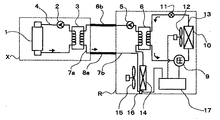
図1において、1はX線管、2は絶縁媒体循環ポンプ、3は絶縁媒体冷却熱交換器、4は絶縁媒体配管、5は2次冷熱媒体循環ポンプ、6は2次冷熱媒体冷却熱交換器、8a、8bは延長2次冷熱媒体配管、9は圧縮機、10は凝縮器、11は減圧手段、12は送風ファン、13は冷媒配管、14は2次冷熱媒体空冷熱交換器、15は送風ファン、16は温度検知手段、17は制御装置、破線で囲まれたXはX線管線源部、Rは冷却装置部で、8a、8bはX線管線源部Xと冷却装置部Rとを接続する可撓性を有する延長2次冷熱媒体配管である。以下では同一機能のものには同一番号を付して説明を省略する。
【0017】
以上のように構成されたX線管冷却装置のうち、圧縮機9、凝縮器10、減圧手段11、送風ファン12、配管13、2次冷熱媒体冷却熱交換器6から構成される冷凍サイクル単独の作動原理について先に説明しておく。冷凍サイクルの作動原理は他の実施の形態でも同じであり、以下では省略することにする。
【0018】
圧縮機9で高温高圧に圧縮されたガス状冷媒は、凝縮器10において送風ファン12により冷却されて高圧の液状冷媒となる。この高圧の液状冷媒は、減圧手段11によって減圧され、この減圧された冷媒は蒸発器となる熱交換器(この実施の形態では2次冷熱媒体冷却熱交換器6)において熱を受け取り蒸発し、再びガス状冷媒となる。冷媒が蒸発する際には多量の熱を潜熱として受け取るため、コンパクトな熱交換器で被冷却媒体を低温に、安定して冷却することができる。蒸発したガス状冷媒は、再び圧縮機9において圧縮され上記したサイクルを繰り返す。
【0019】
以上のように構成された冷凍サイクルによるX線管冷却装置の動作について以下に説明する。X線管1は配管4によって絶縁媒体冷却熱交換器3、絶縁媒体循環ポンプ2と順次接続され、絶縁媒体が密封された状態で循環する構成となっている。また、絶縁媒体冷却熱交換器3は配管7a,8a、7bによって2次冷熱媒体空冷熱交換器14、2次冷熱媒体冷却熱交換器6、2次冷熱媒体循環ポンプ5、配管8bと順次接続され、2次冷熱媒体が封入されて循環する構成となっている。
【0020】
圧縮機9、凝縮器10、減圧手段11、2次冷熱媒体冷却熱交換器6は順次配管13により接続され、冷媒が密封された状態で循環する冷凍サイクルが構成される。減圧手段11としては機械式の膨張弁を用いてもよいし、電動膨張弁を用いてもよいし、キャピラリチューブを用いてもよい。
【0021】
絶縁媒体冷却熱交換器3は、絶縁媒体と2次冷熱媒体が非混合となる熱交換器を用い、例えばプレート式熱交換器を用いてもよいし、二重管式熱交換器を用いてもよい。
【0022】
2次冷熱媒体冷却熱交換器6は、2次冷熱媒体と冷媒が非混合となる熱交換器を用い、同様に例えばプレート式熱交換器を用いてもよいし、二重管式熱交換器を用いてもよい。絶縁媒体としては、X線発生時に電気絶縁可能な媒体であればよく、例えば絶縁油を用いる。2次冷熱媒体としては、熱を搬送する媒体であればよく、水を用いてもよいし、エチレングリコールのようなブラインを用いてもよい。冷凍サイクルの冷媒としては、HFC系冷媒、HCFC系冷媒、HC系冷媒のような冷媒を用い、HFC系冷媒であれば例えばHFC134a(1、2、2、2テトラフルオロエタン)を用いてもよいし、HCFC系冷媒であればHCFC22(クロロジフルオロメタン)を用いてもよいし、HC系冷媒であればイソブタンを用いてもよい。X線管冷却装置は、絶縁媒体が循環する絶縁媒体循環ループと、2次冷熱媒体が循環する2次冷熱媒体循環ループと、冷媒が循環する冷凍サイクルとから構成される。
【0023】
以上のように構成されたX線管冷却装置の動作について図2に示す運転模式図を用いて以下に説明する。図2は横軸に時間をとり、模式的に上段のような電力がX線発生のために供給された場合の冷凍サイクルの運転状態を中段に、主要点の温度を下段に示したもので、運転中の絶縁媒体と2次冷熱媒体の温度変化を示している。
【0024】
X線管冷却装置への通電が行なわれると、絶縁油循環ポンプ2、2次冷熱媒体循環ポンプ5及び、送風ファン15が作動してこれらは運転を開始する。X線装置からのX線放射指令がX線管1に与えられると該X線管からX線が発生し、X線管内部のターゲットからの輻射伝熱により徐々に加熱された絶縁媒体は絶縁媒体冷却熱交換器3で絶縁媒体は冷却され、他方、加熱された2次冷熱媒体が2次冷熱媒体空冷熱交換器14に供給され、外気空気により冷却された後、2次冷熱媒体冷却熱交換器6、2次冷熱媒体循環ポンプ5を経て再び、絶縁媒体冷却熱交換器3に供給される。一方、絶縁媒体冷却熱交換器3で冷却された絶縁媒体は循環ポンプ2によりX線管1に供給され、X線管1を冷却し、加熱された絶縁媒体は再び絶縁媒体冷却熱交換器3に戻り冷却される。
【0025】
X線発生を継続するに従い、絶縁媒体及び、2次冷熱媒体の温度は上昇し、2次冷熱媒体空冷熱交換器14の入口配管に設けた、温度検知手段16が所定温度T_highを超えたことを検知すると、制御装置17は圧縮機9、送風ファン10を起動し、冷凍サイクルを起動する。
【0026】
冷却能力の大きい冷凍サイクルが起動されると、絶縁媒体冷却熱交換器3への2次冷熱媒体供給温度を低下させることができ、絶縁媒体冷却熱交換器3において絶縁媒体の温度上昇を防止することができる。
【0027】
2次冷熱媒体が冷却され、温度検知手段16が、2次冷熱媒体空冷熱交換器14入口温度が所定温度T_low(ここでT_high>T_low)に低下したことを検知すると、制御手段17は圧縮機9、送風ファン12を停止し、冷凍サイクルを停止する。冷凍サイクル停止後は2次冷熱媒体空冷熱交換器14により引き続き冷却が行なわれる。
【0028】
図2から分かるように、運転時間全般において2次冷熱媒体の温度が最も低下するのは、2次冷熱媒体冷却熱交換器6の出口において、冷凍サイクルが停止した時点で生じる。図2に示す結果は、ある一定の室温の場合についてのものである。ここで室温を変えた場合の2次冷熱媒体冷却熱交換器6の出口の2次冷熱媒体温度を比較した模式図を図3に示す。ここでは模式的に上側の図のような電力がX線発生のために供給された場合を考える。A,B,Cはそれぞれ室温がT1、T2、T3の場合(T1>T2>T3)の2次冷熱媒体冷却熱交換器6の出口における2次冷熱媒体温度の時間変化であり、3つの室温条件について同じ制御設定(T_high、T_low)での結果を示したものである。
【0029】
上記の制御によれば、冷凍サイクルの運転が開始するのはA、B、Cの順となり、室温が高いときには冷凍サイクルの運転開始が早くなり、2次冷熱媒体空冷熱交換器14と冷凍サイクルを併用して冷却装置全体の冷却能力を高めて、絶縁媒体温度の過度の温度上昇を防止する。また、冷凍サイクル停止時において2次冷熱媒体温度はC、B、Aの順で高くなり、室温が高いほど冷凍サイクル停止時の2次冷熱媒体温度の最低温度を高くすることができる。
【0030】
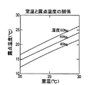
ここで室温と露点温度との間には図4に示すような関係があり、室温が高いほど露点温度が高くなる傾向がある。2次冷熱媒体延長配管8a、8bはX線管部XがX線撮影方向を変える場合にはそれに対応して、自由に変形することが求められるため断熱材などを用いて十分な断熱を施すことが困難となる場合が生じる。上記の実施の形態によれば、室温が高く露点温度が高い場合には、室温が低い場合に対して、2次冷熱媒体の最低温度が高くなるため2次冷熱媒体の配管結露を生じにくくすることができる。
【0031】
また、X線管1の発熱負荷が急増した場合、2次冷熱媒体空冷熱交換器14の入口配管の温度が高くなり、冷却装置部Rでは最も早く負荷の増加を検知できる。温度検知手段16により所定温度T_highを超えたことを検知すると、速やかに冷凍サイクルを起動し冷却能力を増加して、絶縁媒体の温度が過度に上昇することを防止することができる。
【0032】
上記した制御は、温度検知手段16にサーミスタ、或いは感温筒、熱電対といった装置を使用し、制御装置17には例えばサーモスタットのような市販の低価格な装置を使用して実現することができ、室温に応じた配管結露防止のための自己調整機能を有した冷却装置の制御を行なうことができる。
【0033】
また温度検知手段16は冷却装置部Rの内部に設置されるため、発熱源であるX線管部からの信号の伝達は不要であり、信号線の敷設の手間や信号伝送過程でのトラブルが生じるおそれが無い。
【0034】
(第二の実施の形態)
次に別の実施の形態を図5を用いて説明する。
構成は第一の実施の形態とほぼ共通のため、共通の点については説明を省略する。構成上異なるのは温度検知手段16の位置であり、本実施の形態では2次冷熱媒体空冷熱交換器14の出口配管に設置して、冷凍サイクルの運転を制御する。
【0035】
冷却装置の動作についても第一の実施の形態と同じ内容となるので説明を省略するが、第一の実施の形態での設定温度T_highとT_lowは、一般に本実施の形態では別の設定温度T_high2とT_low2となる。
【0036】
本実施の形態によれば第一の実施の形態と同様に、温度検知手段16にはサーミスタ、或いは感温筒、熱電対といった装置を使用し、制御装置17には例えばサーモスタットのような市販の安価な装置を使用して室温に応じた配管結露防止のための自己調整機能を有した冷却装置の制御を行なうことができる。
【0037】
また、温度検知手段16は冷却装置部Rの内部に設置されるため、発熱源であるX線管部からの信号の伝達は不要であり、信号線の敷設の手間や信号伝送過程でのトラブルが生じるおそれが無い。
【0038】
(第三の実施の形態)
次に別の実施の形態を図6を用いて説明する。
図6において18は2次冷熱媒体タンクである。他の構成要素については第一の実施の形態と共通する部分については説明を省略する。本実施の形態では2次冷熱媒体タンク18を2次冷熱媒体冷却熱交換器6と2次冷熱媒体循環ポンプ5の間に設け、2次冷熱媒体冷却熱交換器6で冷却された2次冷熱媒体を所定量貯える。
【0039】
冷凍サイクルの運転停止直後には、圧縮機9の吸込側の冷媒圧力と吐出側の冷媒圧力との両者に、運転中に生じた圧力差が残っている。両者の圧力差に圧縮機9の起動トルクが打ち勝てない場合、圧縮機9が起動できなくなる場合がある。こうした状態を防ぐには両者の圧力差が所定の値以下に小さくなるまで遅延時間をとればよいことが通常、冷凍サイクルを使用する上で広く知られている。
【0040】
本冷却装置において2次冷熱媒体タンク18が無い場合、冷凍サイクル運転停止後に急激にX線発生量が増加し熱負荷が急増すると、場合によっては遅延時間以内に冷凍サイクルの再運転が必要になる場合が生じる。しかしながら2次冷熱媒体タンク18を設置することで、冷凍サイクル運転中に十分冷却された2次冷熱媒体を所定量貯えているため、冷凍サイクル運転停止直後に熱負荷が急増しても、2次冷熱媒体タンク18に貯えられている低温の2次冷熱媒体と2次冷熱媒体空冷熱交換器14の両者によって圧縮機9の再起動に必要な遅延時間を余裕をもって作り出すことができ、大幅な負荷の変動に対して安定した冷却を行なうことが可能となる。
【0041】
また低負荷の入力が続き2次冷熱媒体空冷熱交換器16単独での冷却が長時間続いた後に、熱負荷が急増するような場合には、2次冷熱媒体タンク18内部あるいはタンク出口配管に温度検知手段16を設置していると、2次冷熱媒体タンク18内の2次冷熱媒体の熱容量により温度上昇に時間を要するため、本実施の形態に示すように2次冷熱媒体空冷熱交換器14の入口配管に温度検知手段16を設置する構成とするほうが負荷の急激な変動に対応する上で有効である。
【0042】
或いはまた、図7に示すように2次冷熱媒体冷却熱交換器6は冷凍サイクルの蒸発器となる伝熱管を、2次冷熱媒体タンク18に浸漬させることで構成し、2次冷熱媒体タンク18を2次冷熱媒体冷却熱交換器6と一体化することで構成部品数を少なくしてもよい。
【0043】
さらに図8に示すように2次冷熱媒体循環ポンプ5の吐出側にバイパス配管7cを設け、2次冷熱媒体の一部をバイパスして2次冷熱媒体タンク18内部での2次冷熱媒体流速を高めて2次冷熱媒体冷却熱交換器6での伝熱性能を向上し、2次冷熱媒体冷却熱交換器6を小型化する構成としてもよい。
【0044】
或いは別の方法として、図9に示すように2次冷熱媒体空冷熱交換器14と2次冷熱媒体冷却熱交換器6の間の配管に温度検知手段16を設置する構成とすることで、第二の実施の形態において記したように、前記した内容と同等の効果を得ることができる。
【0045】
さらに、図10に示すように、2次冷熱媒体冷却熱交換器6は冷凍サイクルの蒸発器となる伝熱管を、2次冷熱媒体タンク18に浸漬させることで構成し、2次冷熱媒体タンク18を2次冷熱媒体冷却熱交換器6と一体化することで構成部品数を少なくしてもよい。
【0046】
また、図11に示すように2次冷熱媒体循環ポンプ5の吐出側にバイパス配管7cを設け、2次冷熱媒体の一部をバイパスして2次冷熱媒体タンク18内部での2次冷熱媒体流速を高めて2次冷熱媒体冷却熱交換器6での伝熱性能を向上し、2次冷熱媒体冷却熱交換器6を小型化する構成としてもよい。
【0047】
【発明の効果】
以上説明したように本発明によれば、空冷熱交換器と冷凍サイクルの二つの冷却装置を併用し、空冷熱交換器の入口或いは、出口温度により冷凍サイクルを制御する冷却システムを構成することで、安価な制御装置を用いて室温及び、負荷変動に対しても安定した冷却を行うことが可能なX線管冷却装置を提供することができる。また、2次冷熱媒体冷却熱交換器で冷却された2次冷熱媒体を貯える2次冷熱媒体タンクを設けることで、冷凍サイクル停止直後に熱負荷が急増した場合でも、空冷熱交換器と併せて圧縮機の遅延時間の間冷凍サイクルを停止したままで冷却を行なうことができる。
【図面の簡単な説明】
【図1】本発明によるX線管装置の第一の実施例図。
【図2】本発明によるX線管装置の運転模式図。
【図3】本発明によるX線管装置の運転模式図。
【図4】室温と露点温度の関係図。
【図5】本発明によるX線管装置の第二の実施例図。
【図6】本発明によるX線管装置の第三の実施例図。
【図7】本発明によるX線管装置の第三の実施例の別の実施例図。
【図8】本発明によるX線管装置の第三の実施例の別の実施例図。
【図9】本発明によるX線管装置の第三の実施例の別の実施例図。
【図10】本発明によるX線管装置の第三の実施例の別の実施例図。
【図11】本発明によるX線管装置の第三の実施例の別の実施例図。
【符号の説明】
1・・・X線管、2・・・絶縁媒体循環ポンプ、3・・・絶縁媒体冷却熱交換器、4・・・絶縁媒体配管、5・・・2次冷熱媒体循環ポンプ、6・・・2次冷熱媒体冷却熱交換器、9・・・圧縮機、10・・・凝縮器、11・・・減圧手段、12・・・送風ファン、14・・・2次冷熱媒体冷却空冷熱交換器、15・・・送風ファン、16・・・温度検知手段、17・・・制御装置、18・・・2次冷熱媒体タンク[0001]
BACKGROUND OF THE INVENTION
The present invention relates to an X-ray tube apparatus, and more particularly to an X-ray tube apparatus provided with a cooling device that performs stable cooling against room temperature and load fluctuations.
[0002]
[Prior art]
X-rays used for medical diagnosis and the like are obtained by converting a part of the kinetic energy into X-rays when thermoelectrons accelerated by a high voltage collide with a metal target. However, since most of the kinetic energy of the thermoelectrons colliding with the anode is converted into heat, a large amount of heat is generated from the X-ray tube apparatus, more specifically, the X-ray tube.
[0003]
Therefore, as disclosed in Japanese Patent Laid-Open No. 7-262934, an X-ray tube apparatus is constructed by storing an X-ray tube in a container so as to dissipate heat in an insulating oil. 2. Description of the Related Art Conventionally, an X-ray tube device with an air-cooled cooler that circulates heat generated in a sphere and is transmitted to insulating oil by a pump, leads it to a cooler, and dissipates heat into the ambient air by fan blowing in the cooler has been used.
[0004]
[Problems to be solved by the invention]
Since the cooler of the conventional X-ray tube cooling apparatus performs heat exchange between the ambient air and the insulating oil, the heat dissipation amount is greatly influenced by the temperature of the ambient air, and when the ambient air temperature rises, the heat dissipation amount There is a problem that the temperature of the insulating oil decreases and the temperature of the insulating oil increases.
[0005]
Furthermore, in recent years, in the X-ray diagnostic imaging apparatus, a treatment called interventional radiology (hereinafter referred to as “ΙVR”) in which various surgical operations are performed percutaneously has come to be frequently used. . In addition to conventional examinations, this eyelid VR is a technique in which an operator or an attendant stands in the immediate vicinity of a subject and performs various treatments while observing the subject's X-ray fluoroscopic image. As well as improving the image quality, the X-ray dose emitted from the X-ray tube tends to increase significantly due to the increase in fluoroscopy time and the number of continuous imaging.
[0006]
For this reason, the X-ray tube needs to have a large capacity, thereby increasing the heat generated from the anode. In order to meet the heat generated by the conventional air-cooled cooler, the cooling is required. When the apparatus is enlarged and mounted on the X-ray tube, the X-ray tube main body is enlarged, and the entire X-ray diagnostic imaging apparatus using the apparatus is enlarged. For this reason, not only a large installation space is required, but also the workability at the time of installation, adjustment and maintenance inspection of the X-ray diagnostic imaging apparatus is lowered. It is necessary to install it outside the unit. When using a cooling device that cools the insulating oil by supplying a secondary cooling medium cooled by a cold heat source installed outside to exchange heat with the insulating oil in the X-ray tube, improve the cooling capacity and heat exchange It is ideal to use a cooling source that can lower the secondary cooling medium supply temperature as much as possible and, in some cases, cool to a temperature lower than room temperature.
[0007]
However, when the secondary cooling medium supply temperature is excessively lowered, there is a problem that a part of the cooling device is significantly lower than the dew point temperature and condensation occurs. Therefore, it is desirable to control the cooling device so as to prevent excessive cooling of the cooling device according to the dew point temperature.
[0008]
Since the dew point temperature varies depending on the room temperature and humidity, for example, if the temperature is controlled based on the supply temperature of the secondary cooling medium that has become low temperature after cooling with a cooling source, the dew point temperature is considered to rise when the room temperature rises. Therefore, it becomes necessary to set the temperature higher (according to the highest assumed room temperature and humidity conditions), and the cooling capacity inherent to the cooling device cannot be fully used under normal use conditions. There is. When the dew point temperature is lowered, the cooling device is controlled so as to have a self-adjusting function that lowers the secondary cooling medium supply temperature, which is low, and raises the secondary cooling medium supply temperature when the dew point temperature rises. It is desirable to increase the allowable heat load under normal use conditions. Such control can be easily realized by detecting the room temperature, humidity, and supply temperature and using a control device such as a program controller, but considering the price of the control device, an inexpensive control device such as a thermostat can be used. It is desirable to use and control from a certain temperature.
[0009]
In addition, since the heat load generated by the X-ray tube varies greatly depending on fluoroscopy and imaging conditions, when the heat load increases rapidly, the cooling device quickly detects the increase in heat load and excessively increases the insulating oil temperature. Therefore, it is necessary to cool the X-ray tube apparatus so that it can be operated stably.
[0010]
For this purpose, it is desirable to control the cooling device based on the size of the heat load or the temperature of the X-ray tube part. It is necessary to transmit the signal to the device using a signal line, etc. When installing the cooling device in the adjacent room, the distance of the signal line becomes long, and it may cause trouble in laying or signal transmission process. Garage. For this reason, it becomes a subject for a cooling device to detect the change of a thermal load independently from the temperature change of a secondary cooling medium, and to control driving | operation.
[0011]
The object of the present invention is to provide an X-ray tube cooling device in which the cooling device is installed separately from the X-ray tube section, and it is possible to perform stable cooling against room temperature and load fluctuations using an inexpensive control device. An object of the present invention is to provide an X-ray tube device equipped with a cooling device.
[0012]
[Means for Solving the Problems]
The X-ray tube apparatus of the present invention made to solve the above-described problems is an insulating medium circulating means for circulating an insulating medium that electrically insulates the X-ray tube, and heat exchange of the heat of the insulating medium with a secondary cooling medium. An insulating medium cooling heat exchange means and a case housing the X-ray tube are connected by piping to enclose the insulating medium in a vacuum-tight manner, and the secondary cooling medium includes the insulating medium cooling heat exchange means, and the 2 A secondary cooling medium air cooling heat exchanging means for exchanging heat of the secondary cooling medium with the outside air; a secondary cooling medium cooling heat exchanging means for exchanging heat of the secondary cooling medium with a tertiary cooling medium; and the secondary cooling medium. It circulates in a heat transfer path composed of a secondary cooling medium circulating means for circulating a cooling medium, and the tertiary cooling medium is composed of a compressing means, a condensing means, a decompressing means, and an evaporating means filled with a refrigerant. A refrigerant produced by a refrigeration cycle comprising the secondary cooling medium The rejection heat exchange means constitutes a cooling device for cooling the X-ray tube so as to function as an evaporation means of the refrigeration cycle, and a temperature detection means is provided at least at the inlet or outlet of the secondary cooling medium air cooling heat exchange means. An X-ray tube is cooled by controlling the operation of the refrigeration cycle according to the output of the temperature detecting means.
[0013]
With this configuration, the secondary cooling medium cooling heat exchange means functions as the evaporation means of the refrigeration cycle, thereby improving the cooling capacity, and the inlet and / or outlet of the secondary cooling medium air cooling heat exchange means. Even when the room temperature changes by detecting the temperature of the piping of the section and controlling the operation of the refrigeration cycle, it is possible to prevent dew condensation from occurring in the piping of the secondary cooling medium.
[0014]
In addition, since a secondary cooling medium tank for storing a predetermined amount of the secondary cooling medium cooled by the secondary cooling medium cooling heat exchange means is provided, even if the heat load suddenly increases when the refrigeration cycle is stopped, The supply temperature can be maintained for a predetermined time.
Further, the secondary cooling medium tank can be integrated with the secondary cooling medium cooling heat exchanger means so that the cooling device can be downsized.
[0015]
DETAILED DESCRIPTION OF THE INVENTION
Embodiments of the present invention will be described below with reference to FIGS.
[0016]
(First embodiment)
In FIG. 1, 1 is an X-ray tube, 2 is an insulation medium circulation pump, 3 is an insulation medium cooling heat exchanger, 4 is an insulation medium pipe, 5 is a secondary cooling medium circulation pump, and 6 is a secondary cooling medium cooling heat exchange. 8a and 8b are extended secondary cooling medium pipes, 9 is a compressor, 10 is a condenser, 11 is a decompression means, 12 is a blower fan, 13 is a refrigerant pipe, 14 is a secondary cooling medium air cooling heat exchanger, 15 Is a blower fan, 16 is a temperature detection means, 17 is a control device, X is surrounded by a broken line X is an X-ray tube source unit, R is a cooling device unit, 8a and 8b are X-ray tube source unit X and cooling device unit R Is an extended secondary cooling medium piping having flexibility. In the following, the same functions are denoted by the same reference numerals, and the description thereof is omitted.
[0017]
Of the X-ray tube cooling apparatus configured as described above, the refrigeration cycle alone including the compressor 9, the
[0018]
The gaseous refrigerant compressed to a high temperature and high pressure by the compressor 9 is cooled by the
[0019]
The operation of the X-ray tube cooling device using the refrigeration cycle configured as described above will be described below. The X-ray tube 1 is sequentially connected to an insulating medium cooling heat exchanger 3 and an insulating medium circulation pump 2 by a pipe 4 so that the insulating medium circulates in a sealed state. Further, the insulating medium cooling heat exchanger 3 is sequentially connected to the secondary cooling medium air
[0020]
The compressor 9, the
[0021]
The insulating medium cooling heat exchanger 3 uses a heat exchanger in which the insulating medium and the secondary cooling medium are not mixed. For example, a plate heat exchanger or a double tube heat exchanger may be used. Also good.
[0022]
The secondary cooling medium cooling heat exchanger 6 uses a heat exchanger in which the secondary cooling medium and the refrigerant are not mixed, and similarly, for example, a plate heat exchanger or a double tube heat exchanger may be used. May be used. The insulating medium may be any medium that can be electrically insulated when X-rays are generated. For example, insulating oil is used. The secondary cooling medium may be any medium that transports heat, and water or brine such as ethylene glycol may be used. As the refrigerant for the refrigeration cycle, a refrigerant such as an HFC refrigerant, an HCFC refrigerant, or an HC refrigerant is used. For example, HFC134a (1, 2, 2, 2 tetrafluoroethane) may be used if it is an HFC refrigerant. However, HCFC22 (chlorodifluoromethane) may be used if it is an HCFC-based refrigerant, and isobutane may be used if it is an HC-based refrigerant. The X-ray tube cooling device includes an insulating medium circulation loop in which an insulating medium circulates, a secondary cooling medium circulation loop in which a secondary cooling medium circulates, and a refrigeration cycle in which a refrigerant circulates.
[0023]
The operation of the X-ray tube cooling apparatus configured as described above will be described below with reference to an operation schematic diagram shown in FIG. Fig. 2 shows time on the horizontal axis, schematically showing the operating state of the refrigeration cycle when the power shown in the upper row is supplied to generate X-rays, and the temperature at the main points in the lower row. The temperature change of the insulation medium in operation and the secondary cooling medium is shown.
[0024]
When the X-ray tube cooling device is energized, the insulating oil circulation pump 2, the secondary cooling
[0025]
As the X-ray generation continues, the temperature of the insulating medium and the secondary cooling medium rises, and the temperature detection means 16 provided in the inlet pipe of the secondary cooling medium air
[0026]
When a refrigeration cycle having a large cooling capacity is started, the supply temperature of the secondary cooling medium to the insulating medium cooling heat exchanger 3 can be lowered, and the insulating medium cooling heat exchanger 3 can prevent the temperature of the insulating medium from rising. be able to.
[0027]
When the secondary cooling medium is cooled and the temperature detection means 16 detects that the inlet temperature of the secondary cooling medium air
[0028]
As can be seen from FIG. 2, the temperature of the secondary cooling medium decreases most during the entire operation time when the refrigeration cycle is stopped at the outlet of the secondary cooling medium cooling heat exchanger 6. The results shown in FIG. 2 are for a given room temperature. FIG. 3 is a schematic diagram comparing the secondary cooling medium temperature at the outlet of the secondary cooling medium cooling heat exchanger 6 when the room temperature is changed. Here, a case is considered where the power as shown in the upper diagram is supplied for generating X-rays. A, B, and C are changes in the temperature of the secondary cooling medium at the outlet of the secondary cooling medium cooling heat exchanger 6 when the room temperatures are T1, T2, and T3 (T1>T2> T3), respectively. The results are shown with the same control settings (T_high, T_low) for the conditions.
[0029]
According to the above control, the operation of the refrigeration cycle starts in the order of A, B, and C. When the room temperature is high, the operation of the refrigeration cycle starts earlier, and the secondary cooling medium air
[0030]
Here, there is a relationship as shown in FIG. 4 between the room temperature and the dew point temperature, and the dew point temperature tends to increase as the room temperature increases. The secondary cooling
[0031]
In addition, when the heat generation load of the X-ray tube 1 increases rapidly, the temperature of the inlet pipe of the secondary cooling medium air
[0032]
The above-described control can be realized by using a thermistor, a temperature sensing cylinder, or a thermocouple for the
[0033]
Further, since the temperature detection means 16 is installed inside the cooling device section R, it is not necessary to transmit a signal from the X-ray tube section, which is a heat source, and troubles in laying the signal line and in the signal transmission process are not required. There is no risk of it occurring.
[0034]
(Second embodiment)
Next, another embodiment will be described with reference to FIG.
Since the configuration is substantially the same as that of the first embodiment, description of common points is omitted. The difference in configuration is the position of the temperature detection means 16, and in this embodiment, the temperature detection means 16 is installed in the outlet pipe of the secondary cooling medium air
[0035]
Since the operation of the cooling device is the same as that of the first embodiment, the description thereof is omitted. However, the set temperatures T_high and T_low in the first embodiment are generally different set temperatures T_high2 in this embodiment. And T_low2.
[0036]
According to the present embodiment, as in the first embodiment, a device such as a thermistor, a temperature sensitive cylinder, or a thermocouple is used for the temperature detection means 16, and a commercially available device such as a thermostat is used for the
[0037]
In addition, since the temperature detection means 16 is installed inside the cooling device R, it is not necessary to transmit a signal from the X-ray tube section, which is a heat generation source, and trouble in laying the signal line or in the signal transmission process. There is no risk of occurrence.
[0038]
(Third embodiment)
Next, another embodiment will be described with reference to FIG.
In FIG. 6, 18 is a secondary cooling medium tank. Description of the other components will be omitted for portions common to the first embodiment. In the present embodiment, the secondary
[0039]
Immediately after the operation of the refrigeration cycle is stopped, a pressure difference generated during operation remains in both the refrigerant pressure on the suction side and the refrigerant pressure on the discharge side of the compressor 9. If the starting torque of the compressor 9 cannot overcome the pressure difference between the two, the compressor 9 may not be able to start. In order to prevent such a state, it is generally well known in using a refrigeration cycle that a delay time should be taken until the pressure difference between the two becomes a predetermined value or less.
[0040]
If there is no secondary
[0041]
If the heat load increases rapidly after the low load input continues and the secondary cooling medium air
[0042]
Alternatively, as shown in FIG. 7, the secondary cooling medium cooling heat exchanger 6 is configured by immersing a heat transfer tube serving as an evaporator of the refrigeration cycle in the secondary
[0043]
Further, as shown in FIG. 8, a bypass pipe 7 c is provided on the discharge side of the secondary cooling
[0044]
Alternatively, as shown in FIG. 9, the
[0045]
Further, as shown in FIG. 10, the secondary cooling medium cooling heat exchanger 6 is configured by immersing a heat transfer tube serving as an evaporator of the refrigeration cycle in the secondary
[0046]
Further, as shown in FIG. 11, a bypass pipe 7 c is provided on the discharge side of the secondary cooling
[0047]
【The invention's effect】
As described above, according to the present invention, the two cooling devices of the air cooling heat exchanger and the refrigeration cycle are used together, and the cooling system that controls the refrigeration cycle according to the inlet or outlet temperature of the air cooling heat exchanger is configured. It is possible to provide an X-ray tube cooling device capable of performing stable cooling against room temperature and load fluctuations using an inexpensive control device. In addition, by providing a secondary cooling medium tank that stores the secondary cooling medium cooled by the secondary cooling medium cooling heat exchanger, even if the heat load increases rapidly immediately after the refrigeration cycle is stopped, it is used together with the air cooling heat exchanger. Cooling can be performed while the refrigeration cycle is stopped during the delay time of the compressor.
[Brief description of the drawings]
FIG. 1 is a first embodiment of an X-ray tube apparatus according to the present invention.
FIG. 2 is a schematic operation diagram of the X-ray tube apparatus according to the present invention.
FIG. 3 is an operation schematic diagram of the X-ray tube apparatus according to the present invention.
FIG. 4 is a relationship diagram between room temperature and dew point temperature.
FIG. 5 is a second embodiment of the X-ray tube apparatus according to the present invention.
FIG. 6 is a diagram showing a third embodiment of the X-ray tube apparatus according to the present invention.
FIG. 7 shows another embodiment of the third embodiment of the X-ray tube apparatus according to the present invention.
FIG. 8 is another embodiment diagram of the third embodiment of the X-ray tube apparatus according to the present invention.
FIG. 9 is another embodiment of the third embodiment of the X-ray tube apparatus according to the present invention.
FIG. 10 is another embodiment of the third embodiment of the X-ray tube apparatus according to the present invention.
FIG. 11 is another embodiment of the third embodiment of the X-ray tube apparatus according to the present invention.
[Explanation of symbols]
DESCRIPTION OF SYMBOLS 1 ... X-ray tube, 2 ... Insulation medium circulation pump, 3 ... Insulation medium cooling heat exchanger, 4 ... Insulation medium piping, 5 ... Secondary cooling medium circulation pump, 6 ...・ Secondary cooling medium cooling heat exchanger, 9 ... Compressor, 10 ... Condenser, 11 ... Pressure reducing means, 12 ... Blower fan, 14 ... Secondary cooling medium cooling air
Claims (5)
前記2次冷熱媒体の熱を3次冷熱媒体と熱交換する2次冷熱媒体冷却熱交換手段と、前記絶縁媒体冷却熱交換手段と前記2次冷熱媒体冷却熱交換手段との間で前記2次冷熱媒体を循環させる2次冷熱媒体循環手段と、前記3次冷熱媒体を冷却する3次冷熱媒体冷却手段と、前記2次冷熱媒体冷却熱交換手段に流入する2次冷熱媒体の温度を検知する温度検知手段と、前記温度検知手段の出力に応じて前記3次冷熱媒体冷却手段の運転を制御する制御手段と、を設けたX線管装置において、
前記2次冷熱媒体の熱を外気と熱交換する2次冷却媒体空冷熱交換手段をさらに設けたことを特徴とするX線管装置。Insulating medium circulating means for circulating an insulating medium that electrically insulates the X-ray tube, insulating medium cooling heat exchange means for exchanging heat of the insulating medium with a secondary cooling medium, and a case for housing the X-ray tube Connect with piping and enclose the insulating medium in a vacuum-tight manner ,
The secondary cooling medium cooling heat exchange means for exchanging heat of the secondary cooling medium with the tertiary cooling medium, and the secondary cooling medium between the insulating medium cooling heat exchange means and the secondary cooling medium cooling heat exchange means. The secondary cooling medium circulating means for circulating the cooling medium, the tertiary cooling medium cooling means for cooling the tertiary cooling medium, and the temperature of the secondary cooling medium flowing into the secondary cooling medium cooling heat exchange means are detected. In an X-ray tube apparatus provided with a temperature detection means, and a control means for controlling the operation of the tertiary cooling medium cooling means according to the output of the temperature detection means ,
An X-ray tube apparatus further comprising secondary cooling medium air cooling heat exchange means for exchanging heat of the secondary cooling medium with outside air .
前記2次冷熱媒体冷却熱交換手段は、前記冷凍サイクルの蒸発手段であることを特徴とする請求項1に記載のX線管装置。The tertiary cooling medium cooling means includes a compression means, a condensing means, a decompression means, and an evaporation means, and is a refrigeration cycle formed by enclosing the tertiary cooling medium,
The X-ray tube apparatus according to claim 1, wherein the secondary cooling medium cooling heat exchange unit is an evaporation unit of the refrigeration cycle.
Priority Applications (1)
| Application Number | Priority Date | Filing Date | Title |
|---|---|---|---|
| JP2000359927A JP4731675B2 (en) | 2000-11-27 | 2000-11-27 | X-ray tube device |
Applications Claiming Priority (1)
| Application Number | Priority Date | Filing Date | Title |
|---|---|---|---|
| JP2000359927A JP4731675B2 (en) | 2000-11-27 | 2000-11-27 | X-ray tube device |
Publications (3)
| Publication Number | Publication Date |
|---|---|
| JP2002164196A JP2002164196A (en) | 2002-06-07 |
| JP2002164196A5 JP2002164196A5 (en) | 2008-01-17 |
| JP4731675B2 true JP4731675B2 (en) | 2011-07-27 |
Family
ID=18831607
Family Applications (1)
| Application Number | Title | Priority Date | Filing Date |
|---|---|---|---|
| JP2000359927A Expired - Lifetime JP4731675B2 (en) | 2000-11-27 | 2000-11-27 | X-ray tube device |
Country Status (1)
| Country | Link |
|---|---|
| JP (1) | JP4731675B2 (en) |
Cited By (1)
| Publication number | Priority date | Publication date | Assignee | Title |
|---|---|---|---|---|
| CN102846335A (en) * | 2012-07-31 | 2013-01-02 | 苏州明威医疗科技有限公司 | Device and efficiency evaluation method of air-cooled X-ray machine air cooling system |
Families Citing this family (2)
| Publication number | Priority date | Publication date | Assignee | Title |
|---|---|---|---|---|
| JP2007123211A (en) * | 2005-10-31 | 2007-05-17 | Toshiba Corp | Cooling unit and x-ray tube device |
| KR101239303B1 (en) * | 2013-01-16 | 2013-03-06 | 갑 동 김 | Heat exchange type cooling system for transformer |
Citations (1)
| Publication number | Priority date | Publication date | Assignee | Title |
|---|---|---|---|---|
| JPH02140244U (en) * | 1989-04-27 | 1990-11-22 |
Family Cites Families (7)
| Publication number | Priority date | Publication date | Assignee | Title |
|---|---|---|---|---|
| JPS58164171A (en) * | 1982-03-25 | 1983-09-29 | Kansai Electric Power Co Inc:The | Cell stack of fuel cell |
| JPS58164171U (en) * | 1982-04-26 | 1983-11-01 | 株式会社日立メデイコ | X-ray tube cooling device |
| JPH02140244A (en) * | 1988-11-22 | 1990-05-29 | Bridgestone Corp | Rubber composition |
| JPH0582285A (en) * | 1991-09-19 | 1993-04-02 | Toshiba Corp | X-ray tube cooler |
| JPH0831591A (en) * | 1994-07-13 | 1996-02-02 | Shimadzu Corp | X-ray tube device |
| JPH08215501A (en) * | 1995-02-15 | 1996-08-27 | Tousei Denki Kk | Regenerator for petroleum-based solvent |
| JPH09269154A (en) * | 1996-03-29 | 1997-10-14 | Sanyo Electric Co Ltd | Condenser |
-
2000
- 2000-11-27 JP JP2000359927A patent/JP4731675B2/en not_active Expired - Lifetime
Patent Citations (1)
| Publication number | Priority date | Publication date | Assignee | Title |
|---|---|---|---|---|
| JPH02140244U (en) * | 1989-04-27 | 1990-11-22 |
Cited By (2)
| Publication number | Priority date | Publication date | Assignee | Title |
|---|---|---|---|---|
| CN102846335A (en) * | 2012-07-31 | 2013-01-02 | 苏州明威医疗科技有限公司 | Device and efficiency evaluation method of air-cooled X-ray machine air cooling system |
| CN102846335B (en) * | 2012-07-31 | 2014-11-12 | 苏州明威医疗科技有限公司 | Device and efficiency evaluation method of air-cooled X-ray machine air cooling system |
Also Published As
| Publication number | Publication date |
|---|---|
| JP2002164196A (en) | 2002-06-07 |
Similar Documents
| Publication | Publication Date | Title |
|---|---|---|
| US9772126B2 (en) | Cooling system for high density heat load | |
| JP2008002759A (en) | Binary refrigerating system and cold storage | |
| JP5381572B2 (en) | Refrigeration apparatus diagnosis method, refrigeration apparatus diagnosis apparatus, and refrigeration apparatus | |
| JP2007218459A (en) | Refrigerating cycle device and cool box | |
| JP3983520B2 (en) | Supercritical vapor compression system and suction line heat exchanger for adjusting the pressure of the high pressure component of the refrigerant circulating in the supercritical vapor compression system | |
| TW200426332A (en) | Cooling apparatus | |
| JP2006336943A (en) | Refrigeration system, and cold insulation box | |
| JP2013076491A (en) | Air conditioner | |
| JP2009068728A (en) | Cooling apparatus | |
| JP5636871B2 (en) | Refrigeration equipment | |
| JP4731675B2 (en) | X-ray tube device | |
| JP2008053061A (en) | Cooling system for x-ray photographing apparatus | |
| JP2008051370A (en) | Water cooling type refrigerating system and cold storage equipped with the same | |
| JP4621324B2 (en) | X-ray tube device | |
| JP5056026B2 (en) | vending machine | |
| JP2007218457A (en) | Cooling liquid circulating device | |
| JP7224503B2 (en) | refrigeration cycle equipment | |
| JPH0791753A (en) | Air conditioner | |
| JP2017020687A (en) | Refrigeration cycle apparatus | |
| JP6643711B2 (en) | Refrigeration cycle apparatus and cooling method | |
| CN111608891B (en) | Compressor unit, heat exchange system and water heater | |
| WO2024029567A1 (en) | Binary refrigeration device | |
| US20220364770A1 (en) | Multi-refrigeration-cycle apparatus | |
| JP7241866B2 (en) | refrigeration cycle equipment | |
| KR0176125B1 (en) | Temperature control system using semiconductor and manufacturing apparatus |
Legal Events
| Date | Code | Title | Description |
|---|---|---|---|
| A521 | Written amendment |
Free format text: JAPANESE INTERMEDIATE CODE: A523 Effective date: 20071121 |
|
| A621 | Written request for application examination |
Free format text: JAPANESE INTERMEDIATE CODE: A621 Effective date: 20071121 |
|
| A131 | Notification of reasons for refusal |
Free format text: JAPANESE INTERMEDIATE CODE: A131 Effective date: 20100927 |
|
| A521 | Written amendment |
Free format text: JAPANESE INTERMEDIATE CODE: A523 Effective date: 20101112 |
|
| TRDD | Decision of grant or rejection written | ||
| A01 | Written decision to grant a patent or to grant a registration (utility model) |
Free format text: JAPANESE INTERMEDIATE CODE: A01 Effective date: 20110418 |
|
| A01 | Written decision to grant a patent or to grant a registration (utility model) |
Free format text: JAPANESE INTERMEDIATE CODE: A01 |
|
| A61 | First payment of annual fees (during grant procedure) |
Free format text: JAPANESE INTERMEDIATE CODE: A61 Effective date: 20110420 |
|
| FPAY | Renewal fee payment (event date is renewal date of database) |
Free format text: PAYMENT UNTIL: 20140428 Year of fee payment: 3 |
|
| R150 | Certificate of patent or registration of utility model |
Ref document number: 4731675 Country of ref document: JP Free format text: JAPANESE INTERMEDIATE CODE: R150 Free format text: JAPANESE INTERMEDIATE CODE: R150 |
|
| S111 | Request for change of ownership or part of ownership |
Free format text: JAPANESE INTERMEDIATE CODE: R313111 |
|
| S533 | Written request for registration of change of name |
Free format text: JAPANESE INTERMEDIATE CODE: R313533 |
|
| R350 | Written notification of registration of transfer |
Free format text: JAPANESE INTERMEDIATE CODE: R350 |
|
| EXPY | Cancellation because of completion of term |