JP4727751B2 - Optical network terminator - Google Patents
Optical network terminator Download PDFInfo
- Publication number
- JP4727751B2 JP4727751B2 JP2009538979A JP2009538979A JP4727751B2 JP 4727751 B2 JP4727751 B2 JP 4727751B2 JP 2009538979 A JP2009538979 A JP 2009538979A JP 2009538979 A JP2009538979 A JP 2009538979A JP 4727751 B2 JP4727751 B2 JP 4727751B2
- Authority
- JP
- Japan
- Prior art keywords
- signal
- optical network
- pon
- optical
- downlink signal
- Prior art date
- Legal status (The legal status is an assumption and is not a legal conclusion. Google has not performed a legal analysis and makes no representation as to the accuracy of the status listed.)
- Active
Links
Images


Classifications
-
- H—ELECTRICITY
- H04—ELECTRIC COMMUNICATION TECHNIQUE
- H04Q—SELECTING
- H04Q11/00—Selecting arrangements for multiplex systems
- H04Q11/0001—Selecting arrangements for multiplex systems using optical switching
- H04Q11/0062—Network aspects
- H04Q11/0067—Provisions for optical access or distribution networks, e.g. Gigabit Ethernet Passive Optical Network (GE-PON), ATM-based Passive Optical Network (A-PON), PON-Ring
-
- H—ELECTRICITY
- H04—ELECTRIC COMMUNICATION TECHNIQUE
- H04J—MULTIPLEX COMMUNICATION
- H04J14/00—Optical multiplex systems
- H04J14/02—Wavelength-division multiplex systems
- H04J14/0278—WDM optical network architectures
- H04J14/0282—WDM tree architectures
-
- H—ELECTRICITY
- H04—ELECTRIC COMMUNICATION TECHNIQUE
- H04Q—SELECTING
- H04Q11/00—Selecting arrangements for multiplex systems
- H04Q11/0001—Selecting arrangements for multiplex systems using optical switching
- H04Q11/0062—Network aspects
- H04Q2011/0079—Operation or maintenance aspects
Abstract
Description
本発明は、光アクセスネットワークのユーザ側に設置される光ネットワーク終端装置に関する。 The present invention relates to an optical network termination device installed on the user side of an optical access network.
図1は、光アクセスネットワークの構成例を示す。
図1(a) は、ポイントツーポイントアクセス(1対1)型の光アクセスネットワークの構成例を示す。以下、ポイントツーポイントアクセスを「P−P」という。P−P型の光アクセスネットワークでは、P−P用の光加入者線終端盤(OLT:Optical Line Terminal)101と光ネットワーク終端装置(ONU:Optical Network Unit)102とが、1本の光ファイバ伝送路103を介して1対1で接続される。信号の形式としては、例えば、IEEE(米国電気電子学会)の 802.3委員会で規定されるイーサネット(登録商標)形式が用いられる。FIG. 1 shows a configuration example of an optical access network.
FIG. 1A shows a configuration example of a point-to-point access (one-to-one) type optical access network. Hereinafter, point-to-point access is referred to as “PP”. In a P-P type optical access network, an optical subscriber line terminal board (OLT) 101 for P-P and an optical network unit (ONU) 102 are used as one optical fiber. One-to-one connection is established via the
図1(b) は、パッシブ光ネットワーク(PON:Passive Optical Network)と称されるポイントツーマルチポイントアクセス(1対多)型の光アクセスネットワークの構成例を示す。以下、ポイントツーマルチポイントアクセスを「PON」という。PON型の光アクセスネットワークでは、1つのPON用OLT201とn個(nは自然数)のPON用ONU202−nとが、光ファイバ伝送路203、光スプリッタ235、n本の光ファイバ伝送路204−nを介して1対nで接続される。なお、光加入者線終端盤をOSU(Optical Subscriber Unit)と称し、複数のOSUを収容する装置をOLTと称することもある。ここでは簡単のため、光加入者線終端盤をOLTと称する。
FIG. 1B shows a configuration example of a point-to-multipoint access (one-to-many) type optical access network called a passive optical network (PON). Hereinafter, point-to-multipoint access is referred to as “PON”. In the PON type optical access network, one PON OLT 201 and n (n is a natural number) PON ONUs 202-n are an optical
PONでは、複数のPON用ONU202−nからPON用OLT201に向かう上り信号は、光スプリッタ235で合波する際に互いに送信タイミングが重ならないように帯域を共有して送信される。このようなアクセス方式は、時分割多元接続(TDMA)と称される。PON用OLT201から各PON用ONU202−nに向う下り信号は、各PON用ONU向けの情報を異なる時間フレームに多重して送信される。このような通信技術は、時分割多重(TDM)と称される。PONの構成および動作は、広く知られている(例えば、非特許文献1参照)。
In PON, upstream signals from a plurality of PON ONUs 202-n to the
なお、PONには、イーサネット規格の一部としてIEEE802.3 で標準化されているEPON(Ethernet Passive Optical Network)のほかに、ITU−TにおいてG.984シリーズとして標準化されているGPON(Gigabit capable Passive Optical Network)などがある。EPONの伝送速度は、上りおよび下りの双方とも1.25Gbit/s である。GPONの伝送速度は、上りで1.25Gbit/s 以下であり、下りで 2.5Gbit/s 以下であり、他に622 Mbit/s や1.25Gbit/s などの複数の選択肢がある。 In addition to EPON (Ethernet Passive Optical Network) standardized by IEEE802.3 as part of the Ethernet standard, PON includes GPON (Gigabit capable Passive Optical) standardized as G.984 series by ITU-T. Network). The transmission speed of EPON is 1.25 Gbit / s for both upstream and downstream. The transmission speed of GPON is 1.25 Gbit / s or less for uplink, 2.5 Gbit / s or less for downlink, and there are other options such as 622 Mbit / s and 1.25 Gbit / s.
図2は、P−P用ONUの構成例を示す。
図2において、P−P用ONU102は、図1(a) に示す光ファイバ伝送路103を介してP−P用OLT101と双方向で通信するための双方向光トランシーバ111、ユーザ側の装置と通信するためのユーザネットワークインタフェース(UNI)113、P−P用OLT101と1対1の通信を制御するための信号処理手段112から構成される。FIG. 2 shows a configuration example of the ONU for PP.
In FIG. 2, a P-P ONU 102 includes a bidirectional
図2に示すP−P用ONU102は、イーサネットで規定されるMACフレームを用いて通信を行う例である。信号処理手段112は、双方向光トランシーバ111で受信した下り信号をパラレル化するとともに復号するパラレル化・復号化手段114、上り信号に所定のプリアンブル/SFD(Start of Frame Delimiter)を付与するプリアンブル付与手段116、プリアンブル/SFDを付与した上り信号を符号化するとともにシリアル化して双方向光トランシーバ111へ出力する符号化・シリアル化手段115、および送受信されるMACフレームをヘッダ情報に応じて処理するMAC機能部117を備える。なお、プリアンブル/SFDとは、イーサネット規格において、フレームの開始位置を示すためにフレームの先頭に付与される合計8オクテットのビット列であり、先頭から7オクテットまでは全てアイドル信号「10101010(16進数表記=0x55)」とし、8オクテット目はSFD「10101011(16進数表記=0xd5)」として伝送信号を構成するように定められている(例えば、非特許文献2参照) 。
The ONU 102 for PP shown in FIG. 2 is an example in which communication is performed using a MAC frame defined by Ethernet. The
また、P−P用ONU102に受信する下り信号にも同様のプリアンブルが付与されており、パラレル化・復号化手段114により、フレームの開始位置が特定される。 A similar preamble is also assigned to the downlink signal received by the P-P ONU 102, and the frame start position is specified by the parallelization / decoding means 114.
さらに、信号処理手段112は、必要に応じてOAM(Operations, Administration and Maintenance)機能部118を備えることにより、ONUの通信状態や装置状態の監視制御をOLTから遠隔で行うことができる。また、信号処理手段112は、ユーザから送られてくるデータを通信事業者のネットワークに転送する際に、提供するサービス種類や装置態様によってデータを変換する必要がある場合に、IEEE802.1Dで規定されるブリッジ機能およびIEEE802.1Qで規定されるVLAN(Virtual Local Area Network)機能等を有するブリッジ・VLAN機能部119を搭載する(例えば、非特許文献3参照)。
Further, the
図3は、PON用ONUの構成例を示す。
図3において、PON用ONU202−nは、図1(b) に示す光ファイバ伝送路203,204−nおよび光スプリッタ235を介してPON用OLT201と双方向通信をするための双方向光トランシーバ211、ユーザ側の装置を接続するためのユーザネットワークインタフェース(UNI)213、PON用OLT201と1対多の通信を制御するための信号処理手段212から構成される。FIG. 3 shows a configuration example of the ONU for PON.
In FIG. 3, the PON ONU 202-n performs bidirectional communication with the
図3に示すPON用ONU202−nは、P−PイーサネットをベースとしてEPON用に規定されたMPMC(Multi-Point MAC Control)副層の機能を用いて1対多の通信を行う例である。EPONでは、MPMC副層において規定されるMPCP(Multi-Point Control Protocol)によりTDMAコントロールを実施する。 The PON ONU 202-n shown in FIG. 3 is an example in which one-to-many communication is performed using a function of an MPMC (Multi-Point MAC Control) sublayer defined for EPON based on P-P Ethernet. In EPON, TDMA control is performed by MPCP (Multi-Point Control Protocol) defined in the MPMC sublayer.
信号処理手段212は、図2に示す信号処理手段112が備えるものと同様に動作するパラレル化・復号化手段214、符号化・シリアル化手段215、プリアンブル付与手段216およびMAC機能部217を備え、必要に応じてOAM機能部218およびブリッジ・VLAN機能部219を備える。
The
さらに、信号処理手段212は、パラレル化・復号化手段214で受信した下り信号のプリアンブルから論理リンク番号を読み取るPON用プリアンブル読取手段222と、MPCPによりTDMAコントロールを実施してマルチポイントアクセス制御を行うMPMC機能部220とを備える。
Further, the signal processing means 212 performs PON preamble reading means 222 for reading the logical link number from the preamble of the downlink signal received by the parallelization / decoding means 214, and multipoint access control by performing TDMA control by MPCP. And an MPMC
PON用のプリアンブルは、EPONの規格において、8オクテットのうち先頭から3オクテット目にSLD(Start of LLID Delimiter)を配置し、6〜7オクテット目に論理リンク識別子(LLID:Logical Link Identifier)を配置し、8オクテット目にはプリアンブル部の符号誤りチェック情報(CRC)を配置するように定められている。 In the EPON standard, the SPON (Start of LLID Delimiter) is placed in the 3rd octet of the 8 octets, and the logical link identifier (LLID: Logical Link Identifier) is placed in the 6th to 7th octets. However, it is determined that the code error check information (CRC) of the preamble part is arranged at the 8th octet.
SLDは、従来のイーサネットのMACフレームのプリアンブル領域にLLIDが記載されていることを示すもので、そのビット列は「10101011」と規定されている(例えば、非特許文献4参照)。すなわち、P−P用のMACフレームのプリアンブルの8オクテット目に配置されるSFDと同じビット列である。 The SLD indicates that the LLID is described in the preamble area of the conventional Ethernet MAC frame, and its bit string is defined as “10101011” (for example, see Non-Patent Document 4). That is, it is the same bit string as the SFD arranged at the 8th octet of the preamble of the P-P MAC frame.
なお、双方向光トランシーバ211は、MPMC機能部220から出力される発光制御信号に応じて、図示しない光送信器Tx を発光状態(Enable) または無発光状態(Disable)に切り替える発光制御手段221を備え、自身のPON用ONU202−nに割り当てられた時間スロットのときのみ発光状態に制御される。
The bidirectional
一般的に、P−P型の光アクセスネットワークとPON型の光アクセスネットワークは、ユーザ密度や地理的条件などの適用領域が異なるため、混在して適用されることが多い。 In general, a PP optical access network and a PON optical access network are often applied in a mixed manner because application areas such as user density and geographical conditions are different.
ところで、P−P型とPON型の光アクセスネットワークが混在している場合には、施工者またはユーザが各光アクセスネットワークに対応するONUを誤接続する可能性があった。特に、PON型の光アクセスネットワークにおいて、PON用ONUを接続すべきところを誤ってP−P用ONUを接続した場合に問題が生ずる。P−P用ONUは、PON用OLTからのTDMAコントロールに応じないため、同じ光スプリッタを共有している他のユーザが利用すべき時間スロットにおいて自身の上り信号を送出する。このとき、P−P用ONUが送信する上り信号と、PON型の光アクセスネットワークに接続される他のユーザが正規に送信する上り信号が重なり、他のユーザがPON用OLTと通信できなくなる。このため、例えばP−P用ONUの電源投入時や初期化動作の実行時など、P−P用ONUの動作上の初期状態には光送信器Tx を無発光状態(Disable)に制御する必要である。 By the way, when the P-P type and the PON type optical access networks coexist, there is a possibility that the contractor or the user erroneously connects the ONUs corresponding to the respective optical access networks. In particular, in a PON type optical access network, a problem occurs when a PON ONU is erroneously connected where a PON ONU should be connected. Since the P-P ONU does not respond to the TDMA control from the PON OLT, it transmits its own upstream signal in a time slot that other users sharing the same optical splitter should use. At this time, the uplink signal transmitted by the P-P ONU overlaps the uplink signal normally transmitted by another user connected to the PON type optical access network, and the other user cannot communicate with the PON OLT. Therefore, it is necessary to control the optical transmitter Tx to the non-light emitting state (Disable) in the initial state of the operation of the PP ONU, such as when the power supply of the PP ONU is turned on or when the initialization operation is executed. It is.
本発明は、光アクセスネットワーク構成に対応する下り信号の種別を判別し、下り信号がP−P用であるか否かに応じて光送信器Tx の発光状態の制御が可能なP−P用の光ネットワーク終端装置(ONU)を提供することを目的とする。 The present invention discriminates the type of downlink signal corresponding to the optical access network configuration and can control the light emission state of the optical transmitter Tx depending on whether the downlink signal is for PP or not. An optical network termination unit (ONU) is provided.
また、本発明は、光アクセスネットワーク構成に対応する下り信号の種別を判別し、下り信号がP−P用であるかPON用であるかに応じた信号処理および光送信器Tx の発光状態の制御が可能な多用途型の光ネットワーク終端装置(ONU)を提供することを目的とする。 The present invention also determines the type of downlink signal corresponding to the optical access network configuration, performs signal processing according to whether the downlink signal is for P-P or PON, and the light emission state of the optical transmitter Tx. An object of the present invention is to provide a versatile optical network terminator (ONU) that can be controlled.
上記の課題を解決するために、本発明によるP−P用のONUは、下り信号の種別を判別する信号種別識別手段および双方向光トランシーバにおける発光制御手段を備え、受信する下り信号がP−P用であることを確認してから、上り信号を送信する光送信器を発光状態に制御する。 In order to solve the above-described problem, the ONU for PP according to the present invention includes a signal type identification unit for determining the type of the downlink signal and a light emission control unit in the bidirectional optical transceiver, and the received downlink signal is P- After confirming that it is for P, the optical transmitter that transmits the upstream signal is controlled to be in the light emission state.
また、本発明による多用途型のONUは、下り信号の種別を判別する信号種別識別手段およびONUをP−P用かPON用に切り替える手段を備え、受信する下り信号の種別に応じてP−P用またはPON用のONUとして動作するように制御する。 Further, the versatile ONU according to the present invention includes a signal type identifying means for determining the type of the downlink signal and a means for switching the ONU to P-P or PON, depending on the type of the received downlink signal. It controls to operate as an ONU for P or PON.
第1の発明は、P−P用のOLTと通信を行うONUであって、前記OLTと双方向で通信するための双方向光トランシーバと、前記OLTから送信されて前記双方向光トランシーバで受信した下り信号の種別がP−P用であるか否かを判別し、下り信号の種別の判別結果に応じて前記双方向光トランシーバの光送信器を発光状態または非発光状態に制御するための発光制御信号を出力する信号種別識別手段と、前記発光制御信号に従って前記光送信器を発光状態または非発光状態に制御する発光制御手段とを備え、前記信号種別識別手段は、前記下り信号の種別を判別する前の初期状態では、前記光送信器を非発光状態に制御する発光制御信号を前記発光制御手段に送出し、前記下り信号がP−P用であると判別した後に、前記光送信器を発光状態に制御する発光制御信号を前記発光制御手段に送出する構成であることを特徴とする。 1st invention is ONU which communicates with OLT for P-P, Comprising: The bidirectional | two-way optical transceiver for communicating with the said OLT bidirectionally, It is transmitted from the said OLT, and is received by the said bidirectional | two-way optical transceiver To determine whether the downstream signal type is for P-P, and to control the optical transmitter of the bidirectional optical transceiver to the light emitting state or the non-light emitting state according to the downstream signal type determination result A signal type identifying means for outputting a light emission control signal; and a light emission control means for controlling the optical transmitter to a light emitting state or a non-light emitting state in accordance with the light emission control signal, wherein the signal type identifying means comprises a type of the downstream signal. In an initial state before discriminating the light transmission, a light emission control signal for controlling the optical transmitter to a non-light emission state is sent to the light emission control means, and after determining that the downstream signal is for P-P, the optical transmission Vessel Characterized in that the light emission control signal for controlling the optical state which is configured to be transmitted to the light emission control means.
また、第1の発明のONUにおいて、前記信号種別識別手段は、前記下り信号を前記P−P用の伝送速度で読み取れる場合に、前記下り信号がP−P用であると判別する構成であることを特徴とする。 Further, in the ONU of the first invention, the signal type identification means determines that the downlink signal is for P-P when the downlink signal can be read at the transmission rate for PP. It is characterized by that.
また、第1の発明のONUにおいて、前記ONUは、MACフレームを用いてイーサネット通信を行う装置であり、前記信号種別識別手段は、前記ONUの動作上の初期状態から一定時間内に前記下り信号としてアイドル信号のみを受信する場合、または前記一定時間内にアイドル信号以外の下り信号を受信したときにこの下り信号がP−P用のMACフレームである場合に、前記下り信号をP−P用のイーサネット信号であると判別する構成であることを特徴とする。 In the ONU of the first invention, the ONU is an apparatus that performs Ethernet communication using a MAC frame, and the signal type identification unit is configured to transmit the downlink signal within a predetermined time from an initial state of operation of the ONU. When receiving only the idle signal, or when the downlink signal is a P-P MAC frame when the downlink signal other than the idle signal is received within the predetermined time, the downlink signal is used for the PP. It is the structure which discriminate | determines that it is an Ethernet signal of this.
また、第1の発明のONUにおいて、前記信号種別識別手段は、前記ONUの動作上の初期状態から一定時間内に前記下り信号としてオートネゴシエーション信号を受信する場合に、前記下り信号をP−P用の1ギガビットイーサネット信号であると判別する構成であることを特徴とする。 In the ONU of the first invention, when the signal type identifying means receives the auto-negotiation signal as the downlink signal within a predetermined time from the initial operational state of the ONU, It is the structure which discriminate | determines that it is 1 gigabit Ethernet signal for use.
また、第1の発明のONUにおいて、前記信号種別識別手段は、前記下り信号に対して誤り訂正符号デコードを実施しない状態で66B/64B復号化が正常に行われた場合に、前記下り信号をP−P用の10ギガビットイーサネット信号であると判別する構成であることを特徴とする。 Also, in the ONU of the first invention, the signal type identifying means may receive the downlink signal when 66B / 64B decoding is normally performed without performing error correction code decoding on the downlink signal. It is the structure which discriminate | determines that it is a 10 gigabit Ethernet signal for PP.
第2の発明は、P−P用またはPON用のOLTと通信を行う多用途型のONUであって、前記OLTと双方向で通信するための双方向光トランシーバと、前記OLTから送信されて前記双方向光トランシーバで受信した下り信号の種別を判別し、下り信号の種別の判別結果に応じてアクセス方式を決定する信号種別識別手段と、前記信号種別識別手段で前記下り信号の種別がP−P用であると判別した場合に、前記ONUをP−P用として動作させ、前記信号種別識別手段で前記下り信号の種別がPON用であると判別した場合に、前記ONUをマルチポイントアクセス制御によってPON用として動作させる手段とを備えたことを特徴とする。 A second invention is a versatile ONU that communicates with a P-P or PON OLT, and is transmitted from the OLT, a bidirectional optical transceiver for bidirectional communication with the OLT. A type of downlink signal received by the bidirectional optical transceiver is determined, and a signal type identification unit that determines an access method according to a determination result of the type of downlink signal, and the type of the downlink signal is P by the signal type identification unit. When it is determined that it is for -P, the ONU is operated for P-P, and when the signal type identification means determines that the type of the downstream signal is for PON, the ONU is accessed by multipoint access. And a means for operating as a PON by control.
また、第2の発明のONUにおいて、前記ONUは、MACフレームを用いてP−Pのイーサネット通信またはPONのイーサネット通信を行う装置であり、前記信号種別識別手段は、前記ONUの動作上の初期状態から一定時間内に前記下り信号としてアイドル信号のみを受信する場合、または前記一定時間内にアイドル信号以外の下り信号を受信したときにこの下り信号がP−P用のMACフレームである場合に、前記下り信号をP−P用のイーサネット信号であると判別し、前記一定時間内にアイドル信号以外の下り信号を受信したときにこの下り信号がPON用のMACフレームである場合に、前記下り信号をPON用のイーサネット信号であると判別する構成であることを特徴とする。 In the ONU of the second invention, the ONU is a device that performs a P-P Ethernet communication or a PON Ethernet communication using a MAC frame, and the signal type identification unit is an initial stage of operation of the ONU. When only an idle signal is received as the downlink signal within a certain time from the state, or when this downlink signal is a P-P MAC frame when a downlink signal other than the idle signal is received within the certain time When the downlink signal is a PON MAC frame when the downlink signal is determined to be an Ethernet signal for P-P and a downlink signal other than an idle signal is received within the predetermined time, The configuration is characterized in that the signal is determined to be an Ethernet signal for PON.
また、第2の発明のONUにおいて、前記信号種別識別手段は、前記ONUの動作上の初期状態から一定時間内に前記下り信号としてオートネゴシエーション信号を受信する場合に、前記下り信号をP−P用の1ギガビットイーサネット信号であると判別する構成であることを特徴とする。 In the ONU of the second invention, when the signal type identification means receives the auto-negotiation signal as the downlink signal within a predetermined time from the initial operational state of the ONU, It is the structure which discriminate | determines that it is 1 gigabit Ethernet signal for use.
また、第2の発明のONUにおいて、前記信号種別識別手段は、前記下り信号に対して誤り訂正符号デコードを実施しない状態で66B/64B復号化が正常に行われた場合に、前記下り信号をP−P用の10ギガビットイーサネット信号であると判別し、前記下り信号に対して誤り訂正符号デコードを実施後に66B/64B復号化が正常に行われた場合に、前記下り信号をPON用の10ギガビットイーサネット信号であると判別する構成であることを特徴とする。 Further, in the ONU of the second invention, the signal type identifying means may receive the downlink signal when 66B / 64B decoding is normally performed without performing error correction code decoding on the downlink signal. When it is determined that the signal is a 10-Gigabit Ethernet signal for PP, and the 66B / 64B decoding is normally performed after the error correction code decoding is performed on the downlink signal, the downlink signal is converted to the PON 10 It is the structure which discriminate | determines that it is a gigabit Ethernet signal.
また、第2の発明のONUにおいて、前記信号種別識別手段は、前記下り信号がP−P用のイーサネット信号であると判別した場合に、前記ONUのマルチポイントアクセス制御を無効化するとともに、P−P用のプリアンブルを前記OLTへ送信する上り信号に付与する制御を行い、前記下り信号がPON用のイーサネット信号であると判別した場合に、前記ONUのマルチポイントアクセス制御を有効化するとともに、PON用のプリアンブルを前記上り信号に付与する制御を行う構成であることを特徴とする。 Further, in the ONU of the second invention, the signal type identifying means invalidates the multipoint access control of the ONU and determines that the downlink signal is a P-P Ethernet signal, -When performing control to add a preamble for P to an upstream signal transmitted to the OLT and determining that the downstream signal is an Ethernet signal for PON, the multipoint access control for the ONU is enabled, and The present invention is characterized in that control is performed to give a preamble for PON to the uplink signal.
また、第2の発明のONUにおいて、前記ONUのマルチポイントアクセス制御をバイパス可能とする第1スイッチ手段と、P−P用のプリアンブルを前記上り信号に付与するP−P用プリアンブル付与手段と、PON用のプリアンブルを前記上り信号に付与するPON用プリアンブル付与手段と、前記P−P用プリアンブル付与手段と前記PON用プリアンブル付与手段とを切り替える第2スイッチ手段とを備え、前記信号種別識別手段は、前記下り信号がP−P用のイーサネット信号であると判別した場合に、前記マルチポイントアクセス制御をバイパスするように前記第1スイッチ手段を制御するとともに、前記P−P用プリアンブル付与手段を選択するように前記第2スイッチ手段を制御し、前記下り信号がPON用のイーサネット信号であると判別した場合に、前記マルチポイントアクセス制御を行うように前記第1スイッチ手段を制御するとともに、前記PON用プリアンブル付与手段を選択するように前記第2スイッチ手段を制御する構成であることを特徴とする。 Further, in the ONU of the second invention, a first switch means capable of bypassing the multipoint access control of the ONU, a PP preamble providing means for giving a PP preamble to the uplink signal, PON preamble assigning means for assigning a PON preamble to the upstream signal, and second switch means for switching between the PP preamble assigning means and the PON preamble assigning means, and the signal type identifying means comprises: When the downlink signal is determined to be a P-P Ethernet signal, the first switch unit is controlled to bypass the multipoint access control, and the P-P preamble provision unit is selected. Controlling the second switch means so that the downstream signal is an Ethernet for PON When it is determined that the signal is a signal, the first switch unit is controlled to perform the multipoint access control, and the second switch unit is controlled to select the PON preamble providing unit. It is characterized by that.
また、第2の発明のONUにおいて、前記信号種別識別手段は、前記下り信号の種別を判別する前の初期状態または前記下り信号の種別を判別できないときに、前記双方向光トランシーバの光送信器を非発光状態に制御する構成であることを特徴とする。 Also, in the ONU of the second invention, the signal type identification means can detect the optical transmitter of the bidirectional optical transceiver when it cannot determine the initial state before determining the type of the downlink signal or the type of the downlink signal. It is the structure which controls to a non-light-emission state.
本発明によって、MAC機能を変更することなく、受信する下り信号の種別をP−P用と確認してから発光するONUを実現できる。すなわち、このONUはPONに誤って接続した場合に非発光状態であるので、同じ光スプリッタを利用する他のユーザがPON用OLTと通信できなくなるという問題を回避できる。 According to the present invention, it is possible to realize an ONU that emits light after confirming that the type of downlink signal to be received is for PP without changing the MAC function. That is, since this ONU is in a non-light-emitting state when it is erroneously connected to the PON, it is possible to avoid the problem that other users who use the same optical splitter cannot communicate with the PON OLT.
また、受信する下り信号の種別に応じてP−P用またはPON用として動作する多用途型のONUにより、同様に誤接続による他ユーザの通信停止の問題を回避することができるとともに、P−P用とPON用のONUを共通化でき、種別管理にかかる運用コストを低減させることができる。 In addition, the multi-use ONU that operates as a P-P or a PON according to the type of downlink signal to be received can similarly avoid the problem of communication stoppage of other users due to an erroneous connection, and also the P- The ONU for P and PON can be shared, and the operation cost for the type management can be reduced.
本発明のONUの実施例1〜3について説明する。なお、各実施例において同様の構成要素には同一の参照番号を付して説明する。 Examples 1 to 3 of the ONU of the present invention will be described. In addition, in each Example, the same reference number is attached | subjected and demonstrated to the same component.
(実施例1)
図4は、本発明の実施例1のP−P用ONUの構成例を示す。実施例1のP−P用ONUは、光アクセスネットワーク構成に対応する下り信号がP−P用であることを判別してから、光送信器Tx を無発光状態(Disable)から発光状態(Enable) に制御する構成である。(Example 1)
FIG. 4 shows a configuration example of the PP ONU according to the first embodiment of the present invention. The ONU for PP according to the first embodiment determines that the downlink signal corresponding to the optical access network configuration is for PP, and then changes the optical transmitter Tx from the non-light emitting state (Disable) to the light emitting state (Enable). ) To control.
図4において、P−P用ONU2Aは、双方向光トランシーバ11、UNI13および信号処理手段12Aから構成される。図1(a) に示すP−P用OLT101と1対1で通信を行うための信号処理手段12Aは、パラレル化・復号化手段14、符号化・シリアル化手段15、プリアンブル付与部16、MAC機能部17および信号種別識別手段22Aを備え、必要に応じてOAM機能部18およびブリッジ・VLAN機能部19を備える。
In FIG. 4, the
双方向光トランシーバ11は、図2に示す従来構成と同様に、図1(a) に示すP−P用OLT101と光ファイバ伝送路103を介して双方向通信する機能を有する。ただし、双方向光トランシーバ11は、後述する発光制御手段21を含む。
Similar to the conventional configuration shown in FIG. 2, the bidirectional
UNI13は、図2に示す従来構成と同様に、ユーザ側の装置と通信するためのユーザネットワークインタフェースである。
The
パラレル化・復号化手段14は、図2に示す従来構成と同様に、双方向光トランシーバ11で受信した下り信号をパラレル化するとともに復号する機能を有する。特に、パラレル化・復号化手段14は、下り信号を復号化した8B/10B符号のデコード信号が、所定の時間、正常に受信できているか否かを確認する機能を有する。
The parallelization / decoding means 14 has a function of parallelizing and decoding the downlink signal received by the bidirectional
プリアンブル付与部16は、図2に示す従来構成と同様に、上り信号に所定のプリアンブル/SFDを付与する機能を有する。
The
符号化・シリアル化手段15は、図2に示す従来構成と同様に、プリアンブル/SFDを付与した上り信号を符号化するとともにシリアル化して双方向光トランシーバ11に出力する機能を有する。
The encoding / serialization means 15 has a function of encoding the uplink signal to which the preamble / SFD is added, serializing it, and outputting it to the bidirectional
MAC機能部17は、図2に示す従来構成と同様に、送受信されるMACフレームをヘッダ情報に応じて処理する機能を有する。
Similar to the conventional configuration shown in FIG. 2, the
OAM機能部18は、図2に示す従来構成と同様に、ONUの通信状態や装置状態の監視制御をOLTから遠隔で行う機能を有する。
Similar to the conventional configuration shown in FIG. 2, the
ブリッジ・VLAN機能部19は、図2に示す従来構成と同様に、ユーザから送られてくるデータを通信事業者のネットワークに転送する際に、提供するサービス種類や装置態様によってデータを変換するためのブリッジ機能およびVLAN機能を有する。
As in the conventional configuration shown in FIG. 2, the bridge /
すなわち、実施例1のP−P用ONU2Aと図2に示す従来のP−P用ONU102の相違点は、信号処理手段12Aが信号種別識別手段22Aを備え、双方向光トランシーバ11が発光制御手段21を備えるところにある。
That is, the difference between the
信号種別識別手段22Aは、パラレル化・復号化手段14から入力する下り信号をMAC機能部17に送出するとともに、下り信号がP−P用であるか否かを判別し、下り信号の判別結果に応じた発光制御信号を双方向光トランシーバ11の発光制御手段21に出力する。発光制御手段21は、例えば光送信器Tx のレーザ光源の駆動電流を通電または遮断する回路で構成し、発光制御信号により光送信器Tx の発光状態(Enable) または無発光状態(Disable)に制御する。ここで、発光制御手段21は、ONU2の電源投入時などの動作上の初期状態では光送信器Tx を無発光状態に設定し、下り信号がP−P用であることを示す発光制御信号によって光送信器Tx を発光状態に設定する。また、信号種別識別手段22Aは、下り信号の種別を判別するために所定時間(例えば、3秒)を設定する。
The signal
次に、信号種別識別手段22Aによって、下り信号がP−P用であるか否かを判別する幾つかの方法について説明する。
Next, several methods for determining whether or not the downlink signal is for P-P by the signal
まず、P−P用の伝送速度が、混在しうるPONの下り伝送速度と異なるように設定されている場合に、信号種別識別手段22Aは、パラレル化・復号化手段14で受信した下り信号がP−P用の伝送速度で受信できている場合に、当該下り信号をP−P用であると判別する。例えば、P−P用の伝送速度が 125Mbit/s (ファーストイーサネットの物理伝送速度)であり、混在するPON用の伝送速度が1.25Gbit/s (EPONの物理伝送速度)である場合に、P−P用ONU2AはPON用下り信号を判別できず、P−P用下り信号のみを判別することができる。
First, when the transmission rate for PP is set to be different from the downlink transmission rate of PON that can be mixed, the signal
あるいは、一般的に、双方向光トランシーバ11の光受信器(図示せず)は、特定の伝送速度の信号に対しては正しく識別再生し、それ以外の伝送速度の信号に対しては同期エラー状態となるように構成される。そのため、下り信号がP−P用であるか否かを判別する信号種別識別手段22Aは、双方向光トランシーバ11で同期エラーが解除され、正しく識別再生された下り信号を入力したときに、当該下り信号をP−P用であると判別してもよい。
Alternatively, in general, the optical receiver (not shown) of the bidirectional
次に、P−P用の伝送速度が、混在しうるPONの下り伝送速度と同一であり、両者ともMACフレームによってイーサネット通信を行うように設定されている場合には、次のようにして下り信号の種別を判別する。P−P用ONU2Aの動作上の初期状態から一定時間内に所定のアイドル信号のみを受信する場合、またはこの一定時間内に所定のアイドル信号以外を受信し、それがP−P用のMACフレームである場合に、当該下り信号がP−P用のイーサネット信号であると判別する。例えば、SFD/SLDの前のアイドル信号の繰り返しが所定回数以上であれば、P−P用のイーサネット信号であると判別する。図1(b) に示すPON用OLT201は、一定の時間間隔で、ONUに帯域を通知する制御フレームや新規に接続されたONUを探索(ディスカバリー)する制御フレームを送信するため、下り信号が一定時間内に所定のアイドル信号のみであれば、当該下り信号が図1(b) に示すPON用OLT201から送信されたものでなく、図1(a) に示すP−P用OLT101から送出されたP−P用のイーサネット信号であると判別することができる。
Next, when the transmission rate for PP is the same as the downlink transmission rate of PON that can be mixed, and both are set to perform Ethernet communication using MAC frames, the downlink is performed as follows. Determine the type of signal. When only a predetermined idle signal is received within a predetermined time from the initial operational state of the
PON用OLT201が制御フレームを送出する時間間隔は、システムの設定によって異なるため、前述の「一定時間」の値は、各システムに応じて決定する。典型的には、PON用OLT201が任意のONUに帯域を通知する制御フレームを数ms間隔、新規に接続されたONUを探索(ディスカバリー)する制御フレームを1〜3s間隔で送出すると考えると、「一定時間」は3秒以上の任意の値とすることが好適である。
Since the time interval at which the
次に、信号種別識別手段22Aによって、P−P用ONU2Aの動作上の初期状態から一定時間内に所定のアイドル信号以外を受信したときに、それがP−P用のMACフレームであるか否かを判別する方法について、P−Pシステムが1ギガビットイーサネット、PONシステムがEPONの場合を例にして以下に説明する。
Next, when a signal other than a predetermined idle signal is received within a predetermined time from the initial operational state of the
信号種別識別手段22Aは、1ギガビットイーサネットのSFD、およびPON用のSLDとして共通的に用いられているビット列(10101011(16進数表記=0xd5))の前に、アイドル信号(10101010(16進数表記=0x55))が何回繰り返されているかによって、当該フレームがP−P用であるか否かを判別する。例えば、アイドル信号の繰り返しが所定の回数以上(例えば、3回以上)であれば1ギガビットイーサネット(P−P用)と判別し、所定の回数未満(例えば、3回未満)であればPON用と判別して、両者を識別することができる。なお、各システムに応じてアイドル信号の繰り返し回数を所定の閾値で設定することができる。この繰り返し回数の閾値は、繰り返し判断の信頼性を考慮して3回〜6回のいずれかに設定することが好適である。 The signal type identifying means 22A is preceded by the idle signal (10101010 (hexadecimal notation == 10101010) (hexadecimal notation = Whether or not the frame is for P-P is determined based on how many times 0x55)) is repeated. For example, if the idle signal is repeated a predetermined number of times or more (for example, 3 times or more), it is determined as 1 gigabit Ethernet (for P-P), and if it is less than the predetermined number of times (for example, less than 3 times), for PON And can be identified. Note that the number of repetitions of the idle signal can be set with a predetermined threshold according to each system. The threshold value of the number of repetitions is preferably set to any one of 3 to 6 in consideration of the reliability of repetition determination.
例えば、アイドル信号の繰り返し回数の閾値を7回とした場合、すなわち繰り返しが7回以上でP−P用、繰り返しが7回未満でPON用と判別する場合、何らかの理由でプリアンブルの先頭オクテットが削除された場合に判別誤りを生じる。そのため、下り信号がP−P用であるか否かを判別するアイドル信号の繰り返し回数の閾値は、3回〜6回のいずれかの回数が好ましい。 For example, when the threshold of the number of repetitions of the idle signal is 7 times, that is, when it is determined that the repetition is 7 times or more and for PP, and the repetition is less than 7 times and for PON, the preamble octet is deleted for some reason. If this happens, a determination error occurs. For this reason, the threshold of the number of repetitions of the idle signal for determining whether or not the downstream signal is for PP is preferably any number of 3 to 6.
また、信号種別識別手段22Aは、プリアンブルのSFD/SLDを示す「0xd5(16進)」の後に続く2オクテットのビット列によって、当該フレームがP−P用であるか否かの判別が可能である。PON用のMACフレームでは、SLD(0xd5(16進))に続く2オクテットは「Reserved」と定義されており、通常はプリアンブルと同じアイドル信号になっている。一方、P−P用のMACフレームでは、SFD(0xd5(16進))に続く2オクテットは、当該フレーム(MACフレーム)の宛先アドレス(DA:Destination Addrss)の6オクテットの一部である。MACアドレスの最初の3オクテットは、ベンダIDとしてIEEEが定めた製造企業のIDとなっており、公開されている。このベンダIDとして、先頭の2オクテットに「0x55(16進)」が2つ続くIDは現在のところ使われていない。したがって、SFD/SLDを示す「0xd5(16進)」に続く2オクテットがアイドル信号でなければ、当該フレームがP−P用であると判別することができる。
Further, the signal
また、P−Pシステムが1ギガビットイーサネットの場合は、一定時間内に例えば1000BASE-X Auto Negotiation functionに準じたオートネゴシエーション信号が送受信されるので、信号種別識別手段22Aは、P−P用ONU2Aが動作上の初期状態から一定時間内にオートネゴシエーション信号を受信したときに、当該下り信号をP−P用のイーサネット信号として判別することができる。ただし、10ギガビットイーサネット(10GE)では、オートネゴシエーション信号の送受信が行われないので、当該方法は1ギガビットイーサネットのP−P用システムに限られる。 Further, when the P-P system is 1 gigabit Ethernet, an auto-negotiation signal conforming to, for example, the 1000BASE-X Auto Negotiation function is transmitted / received within a certain period of time. When an auto-negotiation signal is received within a predetermined time from the initial state of operation, the downstream signal can be determined as a P-P Ethernet signal. However, since 10-Gigabit Ethernet (10GE) does not transmit / receive auto-negotiation signals, the method is limited to a 1-Gigabit Ethernet PP system.
また、P−Pシステムが10ギガビットイーサネット(10GE)の場合は、符号化(エンコード)に64B/66B符号を用いているので、信号種別識別手段22Aは、パラレル化・復号化手段14における66B/64B復号化(デコード)の正常性を確認することにより、下り信号をP−P用のイーサネット信号として判別することができる。
When the P-P system is 10 Gigabit Ethernet (10GE), the 64B / 66B code is used for encoding. Therefore, the signal
なお、10ギガビットイーサネットPON(10GE−PON)は、下り信号の伝送速度が10ギガビットイーサネット(10GE)と同じ 10.3125Gbit/s であり、同様に64B/66B符号を用いているが、その下層において誤り訂正符号(FEC)を適用しているため、FECデコードを実施しない段階では66B/64B復号化ができない。したがって、10ギガビットイーサネットでは、FECデコードを実施しない状態で66B/64B復号化(デコード)の正常性確認によりP−P用であるか否かを判別することができる。 In addition, 10 Gigabit Ethernet PON (10GE-PON) has the same downlink signal transmission speed as 10.3125 Gbit / s as 10 Gigabit Ethernet (10GE), and uses 64B / 66B code in the same way. Since a correction code (FEC) is applied, 66B / 64B decoding cannot be performed at a stage where FEC decoding is not performed. Therefore, with 10 Gigabit Ethernet, it is possible to determine whether or not it is for P-P by checking the normality of 66B / 64B decoding (decoding) without performing FEC decoding.
以上説明したように、実施例1のP−P用ONU2Aは、MAC機能部17の設定を変更することなく、信号種別識別手段22Aおよび発光制御手段11の機能により、下り信号がP−P用であることを判別してから光送信器Tx を発光状態(Enable) に制御する。一方、実施例1のP−P用ONU2AをPONに誤って接続したとしても、光送信器Tx は初期設定である無発光状態(Disable)のままである。したがって、図1(b) に示すPONの光スプリッタ235を利用する他のユーザが、P−P用ONUの誤接続のためにPON用OLT201と通信できなくなる問題を回避することができる。
As described above, the
(実施例2)
図5は、本発明の実施例2の多用途型ONUの構成例を示す。実施例2の多用途型ONUは、下り信号がP−P用であるかPON用であるかを判別し、下り信号の種別に応じてP−P用またはPON用として信号処理を行い、かつ光送信器Tx の発光状態を制御する構成である。実施例1と同様の構成要素には、同一の参照番号を付している。(Example 2)
FIG. 5 shows a configuration example of a multi-use ONU according to the second embodiment of the present invention. The multi-use ONU according to the second embodiment determines whether the downlink signal is for P-P or PON, performs signal processing for PP or PON according to the type of downlink signal, and In this configuration, the light emission state of the optical transmitter Tx is controlled. Components similar to those in the first embodiment are denoted by the same reference numerals.
図5において、多用途型ONU2Bは、双方向光トランシーバ11、UNI13および信号処理手段12Bから構成される。P−P用OLTと1対1、またはPON用OLTと1対多で通信を制御するための信号処理手段12Bは、パラレル化・復号化手段14、符号化・シリアル化手段15、プリアンブル付与部16、MAC機能部17、OAM機能部18、ブリッジ・VLAN機能部19、MPMC機能部20、信号種別識別手段22B、MPMC機能有効無効化切替部23およびプリアンブル形式切替部24を備える。
In FIG. 5, the
実施例2において、双方向光トランシーバ11、UNI13、パラレル化・復号化手段14、符号化・シリアル化手段15、MAC機能部17、OAM機能部18およびブリッジ・VLAN機能部19は、実施例1の動作と同様であり、詳細な説明は省略する。
In the second embodiment, the bidirectional
実施例2の多用途型ONU2Bは、実施例1のP−P用ONU2Aと比較して、信号処理手段12Bが実施例1のものから更に機能を付加した信号種別識別手段22B、MPMC機能部20、MPMC機能有効無効化切替部23およびプリアンブル形式切替部24を備え、さらにプリアンブル付与部16は、信号種別識別手段22Bの判別結果に応じたプリアンブル形式切替部24の制御信号に応じて、上り信号を符号化する前に、P−P用またはPON用のプリアンブルを選択して上り信号に付加する機能を備える点で相違する。
The
また、図3に示す従来のPON用ONU202と比較すれば、PON用プリアンブル読取手段222の代わりに信号種別識別手段22Bを備え、MPMC機能有効無効化切替部23およびプリアンブル形式切替部24を備え、さらに双方向光トランシーバ11の発光制御手段21を制御する発光制御信号がMPMC機能部20および信号種別識別手段22Bから送出される点で相違する。
Compared with the
MPMC機能部20は、図3に示す従来のMPMC機能部220と同様に、MPCPによりTDMAコントロールを実施してマルチポイントアクセス制御を行う機能を備える。ただし、MPMC機能部20は、MPMC機能有効無効化切替部23からの制御信号によってMPMC機能を有効化または無効化するように動作する。
Similar to the conventional
信号種別識別手段22Bは、パラレル化・復号化手段14から入力する下り信号をMAC機能部17に出力するとともに、下り信号がP−P用であるかPON用であるかを判別し、判別終了後に光送信器Tx の無発光状態(Disable)を解除して発光状態(Enable) とするための発光制御信号を発光制御手段21に出力し、MPMC機能有効無効化切替部23およびプリアンブル形式切替部24に判別結果に応じた制御信号を出力する。なお、信号種別識別手段22Bは、図3に示す従来のPON用プリアンブル読取手段222の機能を包含し、プリアンブルからLLIDを読み取ってPONのMACフレームであることを識別し、該LLIDをMAC機能部17を介してMPMC機能部20に通知する機能を備える。
The signal type identification unit 22B outputs the downlink signal input from the parallelization /
MPMC機能有効無効化切替部23は、信号種別識別手段22Bによって判別した下り信号の種別に応じて、MPMC機能部20の有効化または無効化を切り替える制御信号を出力する。すなわち、MPMC機能有効無効化切替部23は、下り信号がP−P用であればMPMC機能部20を無効化し、PON用であればMPMC機能部20を有効化する。
The MPMC function validation /
プリアンブル形式切替部24は、信号種別識別手段22によって判別した下り信号の種別に応じて、上り信号のプリアンブルの形式を切り替えるための制御信号をプリアンブル付与部16に出力する。すなわち、プリアンブル形式切替部24は、下り信号がP−P用であればP−P用のプリアンブルを上り信号に付与するようにプリアンブル付与部16を制御し、PON用であればPON用のプリアンブルを上り信号に付与するようにプリアンブル付与部16を制御する。
The preamble format switching unit 24 outputs a control signal for switching the preamble format of the uplink signal to the
多用途型ONU2BをPONに接続したときに他のユーザの通信を妨げる場合として、混在するP−PとPONの伝送速度が同一であり、両者ともMACフレームによってイーサネット通信を行うように設定されている場合について説明する。 When the multipurpose ONU2B is connected to the PON, the transmission rate of the mixed PP and PON is the same, and both are set to perform Ethernet communication using MAC frames. The case will be described.
この場合、信号種別識別手段22Bは、実施例1で説明した場合と同様に、多用途型ONU2Bの動作上の初期状態から一定時間内に所定のアイドル信号のみを受信する場合、またはこの一定時間内に所定のアイドル信号以外を受信し、それがP−P用のMACフレームである場合に、当該下り信号がP−P用のイーサネット信号であると判別する。例えば、SFD/SLDの前のアイドル信号の繰り返しが所定の回数以上であれば、P−P用のイーサネット信号であると判別する。あるいは、多用途型ONU2Bの動作上の初期状態から一定時間内に所定のアイドル信号以外を受信し、それがPON用のMACフレームである場合に、当該下り信号がPON用のイーサネット信号であると判別する。
In this case, the signal type identification unit 22B receives the predetermined idle signal within a predetermined time from the initial state of the operation of the
「一定時間」の値は、実施例1と同様に設定することができる。また、MACフレームがPON用であるかP−P用であるかを判別する方法も、実施例1と同様とすればよい。 The value of “fixed time” can be set in the same manner as in the first embodiment. Also, the method for determining whether the MAC frame is for PON or P-P may be the same as in the first embodiment.
信号種別識別手段22Bは、下り信号をP−P用と判別したときに、その旨を示す制御信号をプリアンブル形式切替部24およびMPMC機能有効無効化切替部23に出力する。プリアンブル形式切替部24はこの制御信号に応じてプリアンブル付与部16を制御し、プリアンブル付与部16は上り信号を符号化する前にP−P用のプリアンブルを上り信号に付与する。また、MPMC機能有効無効化切替部23はこの制御信号に応じてMPMC機能部20を制御し、MPMC機能部20はその機能を無効化する。このようにして、実施例2の多用途型ONU2Bは、MPMC機能部20を無効化するとともに、上り信号のプリアンブルをP−P用に設定することにより、P−P用ONUとして動作する。
When the signal type identifying unit 22B determines that the downlink signal is for PP, the signal type identifying unit 22B outputs a control signal indicating that to the preamble format switching unit 24 and the MPMC function enable / disable switching
また、信号種別識別手段22Bは、下り信号をPON用と判別したときに、その旨を示す制御信号をプリアンブル形式切替部24およびMPMC機能有効無効化切替部23に出力する。プリアンブル形式切替部24はこの制御信号に応じてプリアンブル付与部16を制御し、プリアンブル付与部16は上り信号を符号化する前にPON用のプリアンブルを上り信号に付与する。また、MPMC機能有効無効化切替部23はこの制御信号に応じてMPMC機能部20を制御し、MPMC機能部20はその機能を有効化する。このとき、信号種別識別手段22は、プリアンブルの6〜7オクテット目からLLIDを読み取り、このLLIDをMAC機能部17を介してMPMC機能部20に通知する。このようにして、実施例2の多用途型ONU2Bは、MPMC機能部20を有効化するとともに、上り信号のプリアンブルをPON用に設定することにより、PON用ONUとして動作する。
Further, when the signal type identifying unit 22B determines that the downlink signal is for PON, the signal type identifying unit 22B outputs a control signal indicating that to the preamble format switching unit 24 and the MPMC function enable / disable switching
なお、多用途型ONU2Bが初期状態にあるとき、および信号種別識別手段22が下り信号からP−P用であるかPON用であるかを判別できない状態のときは、信号種別識別手段22Bは、実施例1と同様に機能する発光制御手段21に光送信器Tx を無発光状態(Disable)とする発光制御信号を送出する。これにより、多用途型ONU2Bは、PONに接続したときでも他のユーザの通信を妨げることを回避することができる。
When the
ここで、10ギガビットイーサネットP−Pシステム(10GE)または10ギガビットイーサネットPONシステム(10GE−PON)において、下り信号の種別に応じてP−P用またはPON用として動作する多用途型ONUの構成について説明する。 Here, in the 10 Gigabit Ethernet P-P system (10GE) or the 10 Gigabit Ethernet PON system (10GE-PON), the configuration of the multi-purpose ONU that operates as a P-P or a PON depending on the type of downstream signal explain.
10ギガビットイーサネットに対応する多用途型ONUは、実施例2と同様であるが、パラレル化・復号化手段14および符号化・シリアル化手段15内に10ギガビットイーサネットに特有の機能が加わる。パラレル化・復号化手段14には、パラレル化部および66B/64B復号化部に加えて、同期部、FECデコード部、デスクランブル部、アイドル挿入部が配置される。符号化・シリアル化手段15には、64B/66B符号化部およびシリアル化部に加えて、ギャップ追加部、アイドル削除部、スクランブル部、FECエンコード部、Gearbox 部が配置される。
The versatile ONU corresponding to 10 Gigabit Ethernet is the same as that of the second embodiment, but functions unique to 10 Gigabit Ethernet are added to the parallelizing / decoding means 14 and the encoding / serialization means 15. The parallelization /
信号種別識別手段22Bは、FECデコードを実施せず、66B/64B復号化が正常に(エラーなく)行われた場合は下り信号をP−P用であると判別し、10GE・P−P用ONUとして動作するように設定する。一方、FECデコードを実施後に、66B/64B復号化が正常に(エラーなく)行われた場合は下り信号をPON用であると判別し、10GE−PON用ONUとして動作するように設定する。 The signal type identification means 22B does not perform FEC decoding, and if 66B / 64B decoding is performed normally (without error), it determines that the downstream signal is for P-P, and is for 10GE / P-P. Set to operate as an ONU. On the other hand, if 66B / 64B decoding is performed normally (without error) after the FEC decoding, the downstream signal is determined to be for PON and set to operate as a 10GE-PON ONU.
10GE・P−P用ONUとして動作開始する場合は、信号種別識別手段22Bの制御による有効無効化切替部を介して、MPMC機能部20とともに、FECデコード部、アイドル挿入部、ギャップ追加部、アイドル削除部、FECエンコード部が無効化される。また、プリアンブル形式切替部24の制御により、プリアンブル付与部16で下り信号フレームの先頭にP−P用のプリアンブルが付与される。
When starting operation as an ONU for 10GE / PP, the FMC decoding unit, the idle insertion unit, the gap addition unit, the idle unit together with the
10GE−PON用ONUとして動作開始する場合は、信号種別識別手段22Bの制御による有効無効化切替部を介して、MPMC機能部20とともに、FECデコード部、アイドル挿入部、ギャップ追加部、アイドル削除部、FECエンコード部が有効化される。また、プリアンブル形式切替部24の制御により、プリアンブル付与部16で下り信号フレームの先頭にPON用のプリアンブルが付与される。
When starting operation as an ONU for 10GE-PON, together with the
(実施例3)
図6は、本発明の実施例3のONUの構成を示す。実施例3の多用途型ONUは、実施例2と異なる構成により、下り信号の種別に応じてP−P用ONUまたはPON用ONUとして動作する例を示す。(Example 3)
FIG. 6 shows the configuration of the ONU according to the third embodiment of the present invention. The multi-use ONU of the third embodiment shows an example in which the multi-purpose ONU operates as a P-P ONU or a PON ONU according to the type of downlink signal by a configuration different from that of the second embodiment.
図6において、実施例3の多用途型ONU2Cは、実施例2のMPMC機能有効無効化切替部23に代えて、MPMC機能部20の前後に第1スイッチ手段27−1,27−2および28−1,28−2を配置し、下り信号および上り信号の経路としてMPMC機能部20またはバイパス経路のいずれか一方を選択する構成である。また、実施例2のプリアンブル付与部16およびプリアンブル形式切替部24に代えて、PON用プリアンブル付与部25とP−P用プリアンブル付与部26を並列に配置し、それらの前後に第2スイッチ手段29−1,29−2を配置し、上り信号の経路としてPON用プリアンブル付与部25またはP−P用プリアンブル付与部26のいずれか一方を選択する構成である。
6, the
PON用プリアンブル付与部25は、PON用のプリアンブルを上り信号に付与する機能を備える。P−P用プリアンブル付与部26は、P−P用のプリアンブルを上り信号に付与する機能を備える。多用途型ONU2Cのその他の構成は、実施例2の多用途型ONU2Bと同様である。
The PON
信号種別識別手段22Cは、実施例2と同様に、下り信号がP−P用であるかPON用であるかを判別する。ここで、信号種別識別手段22Cは、下り信号がP−P用であると判別したときに、下り信号および上り信号がMPMC機能部20をバイパスするように第1スイッチ手段27−1,27−2および28−1,28−2を制御するとともに、P−P用プリアンブル付与部26を選択するように第2スイッチ手段29−1,29−2を制御する。下り信号および上り信号がMPMC機能部20をバイパスすることにより、MPMC機能部20が実質的に無効化される。また、信号種別識別手段22Cは、下り信号がPON用であると判別したときに、下り信号および上り信号がMPMC機能部20をバイパスしないように第1スイッチ手段27−1,27−2および28−1,28−2を制御するとともに、PON用プリアンブル付与部25を選択するように第2スイッチ手段29−1,29−2を制御する。下り信号および上り信号がMPMC機能部20をバイパスしないことにより、MPMC機能部20が実質的に有効化される。これにより、実施例2と同様に動作する多用途型ONU2Cを実現することができる。
Similarly to the second embodiment, the signal
以上、説明したように、実施例2,3によれば、従来のPON用ONUと比較して、MAC機能部17およびMPMC機能部20を変更することなく、下り信号の種別を自動判別して、多用途型ONU2B,2CをP−P用ONUまたはPON用ONUとして動作させることができる。これにより、ONUの誤接続による他ユーザの通信停止の問題を回避することができるとともに、P−P用ONUとPON用ONUを共通化でき、種別管理にかかる運用コストを低減させることができる。
As described above, according to the second and third embodiments, it is possible to automatically determine the type of downlink signal without changing the
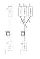
図7は、本発明の実施例2,3において、多用途型ONU2B,2Cを起動してからPON用ONUまたはP−P用ONUとして動作開始するまでの処理手順を示す。
FIG. 7 shows a processing procedure from the activation of the
ステップS1では、多用途型ONU2B,2Cは、起動時またはリセット時に初期状態として双方向光トランシーバ11内の光送信器Txを無発光状態(Disable)にする。これは、前述したように、信号種別識別手段22B,22Cから発光制御手段21に送出される発光制御信号によって制御される。
In step S1, the
ステップS2では、多用途型ONU2B,2Cは、パラレル化・復号化手段14で下り信号の8B/10B符号のデコード信号が正常に受信できているか否かを確認する。これは、8B/10B符号のデコード信号が正常に受信できるまで続けられる(S2−No)。なお、10ギガビットイーサネットの場合には64B/66B符号のデコード信号の正常性が確認される。
In step S2, the
8B/10B符号のデコード信号を正常に受信できた場合(S2−Yes)、ステップS3で多用途型ONU2B,2Cに設けられるタイマ(図示せず)をリセットする。ステップS4では、タイマで所定時間(例えば3秒)を計測しながら、信号種別識別手段22はMACフレームを構成するSFDまたはSLDの出現を待つ。所定時間中にアイドル信号のみを受信してMACフレームを受信しないときにステップS7に進み、光送信器Txの無発光状態を解除して発光状態とし、P−P用ONUとして動作を開始する。
When the decode signal of 8B / 10B code is normally received (S2-Yes), timers (not shown) provided in the
ステップS4において、信号種別識別手段22が所定時間内にMACフレームを受信したときにステップS5に進み、それがP−P用であるかPON用であるかを識別する。ステップS5では、PON用のMACフレーム(例えばEPONフレーム)と判別したときにステップS6に進み、光送信器Txの無発光状態を解除して発光状態とし、PON用ONUとして動作を開始する。また、ステップS5では、P−P用のMACフレーム(例えばGEフレーム)と判別したときにステップS7に進み、光送信器Txの無発光状態を解除して発光状態とし、P−P用ONUとして動作を開始する。
In step S4, when the signal
なお、図7では、最初に受信した1つのMACフレームで判別を完了するように示しているが、これに限定するものではない。例えば、複数個のMACフレームを受信して全てがPON用であればPON用ONUとし、また複数個のMACフレームを受信して全てがP−P用であればP−P用ONUとして動作するようにしてもよい。この場合、それ以外の結果となった場合には、ステップS3のタイマリセットから信号種別識別手段22による判別処理をやり直すようにしてもよい。
Although FIG. 7 shows that the determination is completed with one MAC frame received first, the present invention is not limited to this. For example, if a plurality of MAC frames are received and all are for PON, it is set as a PON ONU, and if a plurality of MAC frames are received and all are for P-P, it operates as a P-P ONU. You may do it. In this case, if any other result is obtained, the determination processing by the signal
また、8B/10B符号のデコード異常が所定時間続く場合には、信号種別識別手段22は光送信器Txを無発光状態(Disable)とし、多用途型ONU2B,2Cを初期状態に戻すようにする。さらに、PON用ONUまたはP−P用ONUとして通信を開始した後でも、8B/10B符号のデコード異常が所定時間続く場合には同様とする。
When the 8B / 10B code decoding abnormality continues for a predetermined time, the signal
ところで、PONでは図1(b) に示すように、OLTとONUの間に光ファイバに加えて光スプリッタが配置されるため、PON用ONUの送信光パワーは、P−P用ONUの送信光パワーよりも高いレベルに設定される場合がある。このレベル差を吸収するために、実施例2および実施例3のONU2B,2Cは、送信光パワーのレベルを調整する送信光パワー調整手段(図示せず)を備えてもよい。送信光パワー調整手段は、下り信号の種別がP−P用であるかPON用であるかを示す信号種別識別手段22による判別結果に応じて、送信光パワー調整手段により送信光パワーを切り替えるように動作する。この送信光パワー調整手段は、レーザ光源の駆動電流を調整するものでもよいし、光減衰器であってもよい。
In the PON, as shown in FIG. 1B, since an optical splitter is disposed between the OLT and the ONU in addition to the optical fiber, the transmission optical power of the PON ONU is the transmission light of the P-P ONU. It may be set to a level higher than the power. In order to absorb this level difference, the
また、同様の理由で、PON用ONUの受信光パワー範囲、つまり受信光パワーの上限および下限は、P−P用ONUの受信光パワーの上限および下限よりも、それぞれ低いレベルに設定される場合がある。この差を吸収するために、実施例2および実施例3のONU2B,2Cは、受信光パワーの上限および下限を上下に調整することができる受信光パワー調整手段を備えてもよい。受信光パワー調整手段は、下り信号の種別がP−P用であるかPON用であるかを示す信号種別識別手段22による判別結果に応じて、受信光パワー(上限および下限)を切り替えるように動作する。この受信光パワー調整手段は、アバランシェフォトダイオードの増倍率を変更させて受信光パワーを変化させるものでもよいし、光減衰器であってもよい。
For the same reason, the received optical power range of the PON ONU, that is, the upper limit and the lower limit of the received optical power are set lower than the upper and lower limits of the received optical power of the P-P ONU, respectively. There is. In order to absorb this difference, the
なお、初期状態など、下り信号の種別が不明な段階では、下り信号の種別が確認できるまで受信光パワーの上下を繰り返す必要がある。 It should be noted that at a stage where the downlink signal type is unknown, such as in the initial state, it is necessary to repeat the increase and decrease of the received optical power until the downlink signal type can be confirmed.
さらに、図8〜10に示すように、実施例1のP−P用ONU2A、実施例2および実施例3の多用途型ONU2Bおよび多用途型ONU2Cは、WDMアクセスネットワークにも適用することができる。説明の便宜のため、同様な構成要素には、同一の参照番号を付している。
Furthermore, as shown in FIGS. 8 to 10, the
図8は、P−P型のWDM光アクセスネットワークの構成例を示す。
図8において、局装置31に収容されるP−P用OLT51−1〜P−P用OLT51−mと、各ユーザ対応のP−P用ONU2A−1〜P−P用ONU2A−mは、波長多重分離器30−1、光ファイバ伝送路33、波長多重分離器30−2、光ファイバ伝送路34−1〜34−mを介して接続される。ここで、mはユーザ数および波長多重数に相当する整数である。FIG. 8 shows a configuration example of a PP type WDM optical access network.
In FIG. 8, the PLT PLT OLT 51-1 to the PLT OLT 51-m accommodated in the
P−P用OLT51−1とP−P用ONU2A−1は、下り信号波長λ1 および上り信号波長λ1'を用いて1対1の通信を行う。同様にP−P用OLT51−mとP−P用ONU2A−mは、下り信号波長λm および上り信号波長λm'を用いて1対1の通信を行う。波長λ1 〜λm の下り信号および波長λ1'〜λm'の上り信号は、波長多重分離器30−1,30−2で波長多重して光ファイバ伝送路33を波長多重伝送され、波長多重分離器30−2,30−1で波長分離される。このため、各P−P用ONU2A−1〜2A−mでは、それぞれ割り当てられた波長を用いて、対応するP−P用OLT51−1〜51−mと個別に1対1通信を行うことができる。
The PLT OLT 51-1 and the
図9は、PON型のWDM光アクセスネットワークの構成例を示す。
図9において、局装置31に収容されるPON用OLT52−1〜PON用OLT52−mと、各ユーザ対応の多用途型ONU2B−11〜多用途型ONU2B−mnは、波長多重分離器30−1、光ファイバ伝送路33、波長多重分離器30−2、光ファイバ伝送路34−1〜34−m、光スプリッタ35−1〜35−mを介して接続される。ここで、nは1つのPON用OLTと1対nのポイントツーマルチポイント通信するユーザ数、mは波長多重数に相当する整数である。FIG. 9 shows a configuration example of a PON type WDM optical access network.
In FIG. 9, the PON OLT 52-1 to PON OLT 52 -m accommodated in the
PON用OLT52−1と多用途型ONU2B−11〜多用途型ONU2B−1nは、下り信号波長λ1 および上り信号波長λ1'を用いて1対nのポイントツーマルチポイント通信を行う。同様にPON用OLT52−mと多用途型ONU2B−m1〜多用途型ONU2B−mnは、下り信号波長λm および上り信号波長λm'を用いて1対nのポイントツーマルチポイント通信を行う。波長λ1 〜λm の下り信号および波長λ1'〜λm'の上り信号は、波長多重分離器30−1,30−2で波長多重して光ファイバ伝送路33を波長多重伝送され、波長多重分離器30−2,30−1で波長分離される。このため、各波長ごとにn個の多用途型ONUはPON型ONUとして、対応するPON用OLTと1対nのポイントツーマルチポイント通信を行うことができる。
The PON OLT 52-1 and the
図10は、P−P/PON混在型のWDM光アクセスネットワークの構成例を示す。
図10において、局装置31に収容されるP−P用OLT51−1と、ユーザ側のP−P用ONU2A−1は、波長多重分離器30−1、光ファイバ伝送路33、波長多重分離器30−2、光ファイバ伝送路34−1を介して接続され、下り信号波長λ1 、上り信号波長λ1'を用いて1対1の通信を行う。FIG. 10 shows a configuration example of a P-P / PON mixed WDM optical access network.
In FIG. 10, a PLT OLT 51-1 accommodated in a
局装置31に収容されるPON用OLT52−mと、ユーザ側の多用途型ONU2B−m1〜多用途型ONU2B−mnは、波長多重分離器30−1、光ファイバ伝送路33、波長多重分離器30−2、光ファイバ伝送路34−m、光スプリッタ35−mを介して接続され、下り信号波長λm および上り信号波長λm'を用いて1対nのポイントツーマルチポイント通信を行う。
The PON OLT 52-m accommodated in the
このように、波長ごとにP−P型とPON型にそれぞれ対応するWDM光アクセスネットワークを構成することができる。すなわち、P−P用ONU2A−1では、下り信号波長λ1 、上り信号波長λ1'を用いて時間領域を占有したP−P用の通信を行う。また、多用途型ONU2B−m1〜多用途型ONU2B−mnでは、下り信号波長λm および上り信号波長λm'を用いて時間領域を共有したPON型のポイントツーマルチポイント通信を行う。
Thus, a WDM optical access network corresponding to each of the P-P type and the PON type can be configured for each wavelength. That is, the
図8〜10に示すように、P−P型、PON型、P−P/PON混在型のWDM光アクセスネットワークにおいて、P−P用ONUあるいはPON用ONUとして、図4に示す実施例1のP−P用ONU2A、図5に示す実施例2の多用途型ONU2Bまたは図6に示す実施例3の多用途型ONU2Cを用いることにより、波長ごとにONUの誤接続による他ユーザの通信停止の問題を回避することができる。また、多用途型ONUを用いることにより、P−P用ONUとPON用ONUを共通化でき、種別管理にかかる運用コストを低減させることができる。
As shown in FIGS. 8 to 10, in the P-P type, the PON type, and the P / P / PON mixed type WDM optical access network, the P-P ONU or the PON ONU of the first embodiment shown in FIG. By using the
なお、図8に示すP−P型のWDM光アクセスネットワークをWDM−PON光アクセスネットワークと呼び、図9に示すPON型のWDM光アクセスネットワークをWDM/TDM−PON光アクセスネットワークと呼ぶこともあるが、本明細書ではポイントツーマルチポイントで送受信制御を行う形態をPONとしている。 8 may be referred to as a WDM-PON optical access network, and the PON type WDM optical access network illustrated in FIG. 9 may be referred to as a WDM / TDM-PON optical access network. However, in this specification, the form of performing transmission / reception control in a point-to-multipoint manner is PON.
前述した実施例では、説明の便宜のために、各手段を個別の手段として説明したが、適宜組み合わせて、または1つの制御手段で構成することができることは明らかである。従って、本発明は、前述した実施例に限定されるものではなく、その主旨を逸脱しない範囲において種々変更可能である。 In the embodiment described above, each means has been described as an individual means for convenience of explanation. However, it is obvious that they can be appropriately combined or configured by one control means. Therefore, the present invention is not limited to the above-described embodiments, and various modifications can be made without departing from the spirit of the present invention.
本発明によれば、ONUが下り信号の種別(P−P用,PON用)を判別し、P−P型光アクセスネットワークおよびPON型光アクセスネットワークが混在する構成でも安全に対応することができるので、伝送データを送受信する光アクセスネットワークシステムに有用である。 According to the present invention, the ONU discriminates the type of downlink signal (for P-P, for PON), and can safely cope with a configuration in which a P-P type optical access network and a PON-type optical access network are mixed. Therefore, it is useful for an optical access network system that transmits and receives transmission data.
Claims (12)
前記OLTと双方向で通信するための双方向光トランシーバと、
前記OLTから送信されて前記双方向光トランシーバで受信した下り信号の種別がP−P用であるか否かを判別し、下り信号の種別の判別結果に応じて前記双方向光トランシーバの光送信器を発光状態または非発光状態に制御するための発光制御信号を出力する信号種別識別手段と、
前記発光制御信号に従って前記光送信器を発光状態または非発光状態に制御する発光制御手段とを備え、
前記信号種別識別手段は、前記下り信号の種別を判別する前の初期状態では、前記光送信器を非発光状態に制御する発光制御信号を前記発光制御手段に送出し、前記下り信号がP−P用であると判別した後に、前記光送信器を発光状態に制御する発光制御信号を前記発光制御手段に送出する構成である
ことを特徴とする光ネットワーク終端装置。An optical network termination device for communicating with an optical subscriber line termination board (hereinafter referred to as OLT) for point-to-point access (hereinafter referred to as PP),
A bidirectional optical transceiver for bidirectional communication with the OLT;
It is determined whether or not the downlink signal type transmitted from the OLT and received by the bidirectional optical transceiver is for P-P, and the optical transmission of the bidirectional optical transceiver is performed according to the determination result of the downlink signal type. A signal type identifying means for outputting a light emission control signal for controlling the light emitting state or the non-light emitting state;
Emission control means for controlling the optical transmitter to a light emitting state or a non-light emitting state according to the light emission control signal,
The signal type identification means sends a light emission control signal for controlling the optical transmitter to a non-light emission state to the light emission control means in an initial state before determining the type of the downstream signal, and the downstream signal is P− An optical network terminator characterized in that after determining that it is for P, a light emission control signal for controlling the optical transmitter to a light emission state is sent to the light emission control means.
前記信号種別識別手段は、前記下り信号を前記P−P用の伝送速度で読み取れる場合に、前記下り信号がP−P用であると判別する構成である
ことを特徴とする光ネットワーク終端装置。The optical network termination device according to claim 1,
The optical network termination device, wherein the signal type identification unit is configured to determine that the downlink signal is for PP when the downlink signal can be read at the transmission rate for PP.
前記光ネットワーク終端装置は、MACフレームを用いてイーサネット通信を行う装置であり、
前記信号種別識別手段は、前記光ネットワーク終端装置の動作上の初期状態から一定時間内に前記下り信号としてアイドル信号のみを受信する場合、または前記一定時間内にアイドル信号以外の下り信号を受信したときにこの下り信号がP−P用のMACフレームである場合に、前記下り信号をP−P用のイーサネット信号であると判別する構成である
ことを特徴とする光ネットワーク終端装置。In the optical network termination device according to claim 1 or 2,
The optical network termination device is a device that performs Ethernet communication using a MAC frame,
The signal type identification unit receives only an idle signal as the downlink signal within a predetermined time from an initial state of operation of the optical network termination device, or receives a downstream signal other than the idle signal within the predetermined time An optical network terminator characterized in that when the downlink signal is a P-P MAC frame, the downlink signal is determined to be a P-P Ethernet signal.
前記信号種別識別手段は、前記光ネットワーク終端装置の動作上の初期状態から一定時間内に前記下り信号としてオートネゴシエーション信号を受信する場合に、前記下り信号をP−P用の1ギガビットイーサネット信号であると判別する構成である
ことを特徴とする光ネットワーク終端装置。In the optical network termination device according to claim 1 or 2,
When the signal type identification means receives an auto-negotiation signal as the downlink signal within a predetermined time from the initial operational state of the optical network termination device, the downlink signal is converted to a 1-Gb Ethernet signal for PP. An optical network terminator characterized by having a configuration for discriminating that it exists.
前記信号種別識別手段は、前記下り信号に対して誤り訂正符号デコードを実施しない状態で66B/64B復号化が正常に行われた場合に、前記下り信号をP−P用の10ギガビットイーサネット信号であると判別する構成である
ことを特徴とする光ネットワーク終端装置。In the optical network termination device according to claim 1 or 2,
When the 66B / 64B decoding is normally performed in a state where error correction code decoding is not performed on the downlink signal, the signal type identification unit uses the 10-Gigabit Ethernet signal for PP as the downlink signal. An optical network terminator characterized by having a configuration for discriminating that it exists.
前記OLTと双方向で通信するための双方向光トランシーバと、
前記OLTから送信されて前記双方向光トランシーバで受信した下り信号の種別を判別し、下り信号の種別の判別結果に応じてアクセス方式を決定する信号種別識別手段と、
前記信号種別識別手段で前記下り信号の種別がP−P用であると判別した場合に、前記光ネットワーク終端装置をP−P用として動作させ、前記信号種別識別手段で前記下り信号の種別がPON用であると判別した場合に、前記光ネットワーク終端装置をマルチポイントアクセス制御によってPON用として動作させる手段と
を備えたことを特徴とする光ネットワーク終端装置。An optical network termination device that communicates with an optical subscriber line termination board (hereinafter referred to as OLT) for point-to-point access (hereinafter referred to as P-P) or point-to-multipoint access (hereinafter referred to as PON). ,
A bidirectional optical transceiver for bidirectional communication with the OLT;
A signal type identifying means for determining a type of a downlink signal transmitted from the OLT and received by the bidirectional optical transceiver, and determining an access method according to a determination result of the type of the downlink signal;
When the signal type identification means determines that the downlink signal type is for PP, the optical network termination device is operated for PP, and the signal type identification means determines the downlink signal type. An optical network terminator comprising: means for operating the optical network terminator for PON by multipoint access control when it is determined that the optical network terminator is for PON.
前記光ネットワーク終端装置は、MACフレームを用いてP−Pのイーサネット通信またはPONのイーサネット通信を行う装置であり、
前記信号種別識別手段は、前記光ネットワーク終端装置の動作上の初期状態から一定時間内に前記下り信号としてアイドル信号のみを受信する場合、または前記一定時間内にアイドル信号以外の下り信号を受信したときにこの下り信号がP−P用のMACフレームである場合に、前記下り信号をP−P用のイーサネット信号であると判別し、前記一定時間内にアイドル信号以外の下り信号を受信したときにこの下り信号がPON用のMACフレームである場合に、前記下り信号をPON用のイーサネット信号であると判別する構成である
ことを特徴とする光ネットワーク終端装置。The optical network termination device according to claim 6, wherein
The optical network termination device is a device that performs P-P Ethernet communication or PON Ethernet communication using a MAC frame,
The signal type identification unit receives only an idle signal as the downlink signal within a predetermined time from an initial state of operation of the optical network termination device, or receives a downstream signal other than the idle signal within the predetermined time Sometimes, when this downlink signal is a P-P MAC frame, it is determined that the downlink signal is a P-P Ethernet signal, and a downlink signal other than an idle signal is received within the predetermined time. An optical network terminator characterized in that when the downstream signal is a MAC frame for PON, the downstream signal is determined to be an Ethernet signal for PON.
前記信号種別識別手段は、前記光ネットワーク終端装置の動作上の初期状態から一定時間内に前記下り信号としてオートネゴシエーション信号を受信する場合に、前記下り信号をP−P用の1ギガビットイーサネット信号であると判別する構成である
ことを特徴とする光ネットワーク終端装置。The optical network termination device according to claim 6, wherein
When the signal type identification means receives an auto-negotiation signal as the downlink signal within a predetermined time from the initial operational state of the optical network termination device, the downlink signal is converted to a 1-Gb Ethernet signal for PP. An optical network terminator characterized by having a configuration for discriminating that it exists.
前記信号種別識別手段は、前記下り信号に対して誤り訂正符号デコードを実施しない状態で66B/64B復号化が正常に行われた場合に、前記下り信号をP−P用の10ギガビットイーサネット信号であると判別し、前記下り信号に対して誤り訂正符号デコードを実施後に66B/64B復号化が正常に行われた場合に、前記下り信号をPON用の10ギガビットイーサネット信号であると判別する構成である
ことを特徴とする光ネットワーク終端装置。The optical network termination device according to claim 6, wherein
When the 66B / 64B decoding is normally performed in a state where error correction code decoding is not performed on the downlink signal, the signal type identification unit uses the 10-Gigabit Ethernet signal for PP as the downlink signal. When the 66B / 64B decoding is normally performed after error correction code decoding is performed on the downlink signal, the downlink signal is determined to be a 10 Gbps Ethernet signal for PON. An optical network terminator characterized by being.
前記信号種別識別手段は、前記下り信号がP−P用のイーサネット信号であると判別した場合に、前記光ネットワーク終端装置のマルチポイントアクセス制御を無効化するとともに、P−P用のプリアンブルを前記OLTへ送信する上り信号に付与する制御を行い、前記下り信号がPON用のイーサネット信号であると判別した場合に、前記光ネットワーク終端装置のマルチポイントアクセス制御を有効化するとともに、PON用のプリアンブルを前記上り信号に付与する制御を行う構成である
ことを特徴とする光ネットワーク終端装置。In the optical network termination device according to any one of claims 6 to 9,
The signal type identification means invalidates the multipoint access control of the optical network termination device and determines the P-P preamble when the downlink signal is determined to be a P-P Ethernet signal. When control is given to an upstream signal to be transmitted to the OLT and it is determined that the downstream signal is an Ethernet signal for PON, multipoint access control of the optical network termination device is enabled and a preamble for PON An optical network terminator characterized in that the control is performed to give the uplink signal to the uplink signal.
前記光ネットワーク終端装置のマルチポイントアクセス制御をバイパス可能とする第1スイッチ手段と、
P−P用のプリアンブルを前記上り信号に付与するP−P用プリアンブル付与手段と、
PON用のプリアンブルを前記上り信号に付与するPON用プリアンブル付与手段と、
前記P−P用プリアンブル付与手段と前記PON用プリアンブル付与手段とを切り替える第2スイッチ手段とを備え、
前記信号種別識別手段は、前記下り信号がP−P用のイーサネット信号であると判別した場合に、前記マルチポイントアクセス制御をバイパスするように前記第1スイッチ手段を制御するとともに、前記P−P用プリアンブル付与手段を選択するように前記第2スイッチ手段を制御し、前記下り信号がPON用のイーサネット信号であると判別した場合に、前記マルチポイントアクセス制御を行うように前記第1スイッチ手段を制御するとともに、前記PON用プリアンブル付与手段を選択するように前記第2スイッチ手段を制御する構成である
ことを特徴とする光ネットワーク終端装置。In the optical network termination device according to any one of claims 6 to 9,
First switch means capable of bypassing multipoint access control of the optical network termination device;
P-P preamble providing means for applying a P-P preamble to the upstream signal;
A PON preamble providing means for adding a PON preamble to the upstream signal;
A second switch means for switching between the PP preamble applying means and the PON preamble applying means;
The signal type identification unit controls the first switch unit to bypass the multipoint access control when the downlink signal is determined to be an Ethernet signal for PP, and the PP The second switch means is controlled to select a preamble providing means for use, and when it is determined that the downlink signal is an Ethernet signal for PON, the first switch means is configured to perform the multipoint access control. An optical network terminator characterized by controlling the second switch means so as to select the PON preamble providing means.
前記信号種別識別手段は、前記下り信号の種別を判別する前の初期状態または前記下り信号の種別を判別できないときに、前記双方向光トランシーバの光送信器を非発光状態に制御する構成である
ことを特徴とする光ネットワーク終端装置。In the optical network termination device according to any one of claims 6 to 9,
The signal type identification unit is configured to control the optical transmitter of the bidirectional optical transceiver to a non-light-emitting state when the initial state before determining the type of the downlink signal or the type of the downlink signal cannot be determined. An optical network termination device.
Priority Applications (1)
| Application Number | Priority Date | Filing Date | Title |
|---|---|---|---|
| JP2009538979A JP4727751B2 (en) | 2007-11-01 | 2008-09-18 | Optical network terminator |
Applications Claiming Priority (4)
| Application Number | Priority Date | Filing Date | Title |
|---|---|---|---|
| JP2007285110 | 2007-11-01 | ||
| JP2007285110 | 2007-11-01 | ||
| PCT/JP2008/066826 WO2009057392A1 (en) | 2007-11-01 | 2008-09-18 | Optical network unit |
| JP2009538979A JP4727751B2 (en) | 2007-11-01 | 2008-09-18 | Optical network terminator |
Publications (2)
| Publication Number | Publication Date |
|---|---|
| JPWO2009057392A1 JPWO2009057392A1 (en) | 2011-03-10 |
| JP4727751B2 true JP4727751B2 (en) | 2011-07-20 |
Family
ID=40521568
Family Applications (1)
| Application Number | Title | Priority Date | Filing Date |
|---|---|---|---|
| JP2009538979A Active JP4727751B2 (en) | 2007-11-01 | 2008-09-18 | Optical network terminator |
Country Status (5)
| Country | Link |
|---|---|
| US (1) | US8340520B2 (en) |
| EP (1) | EP2207310B1 (en) |
| JP (1) | JP4727751B2 (en) |
| CN (1) | CN101843047B (en) |
| WO (1) | WO2009057392A1 (en) |
Families Citing this family (19)
| Publication number | Priority date | Publication date | Assignee | Title |
|---|---|---|---|---|
| US8855490B2 (en) * | 2007-08-31 | 2014-10-07 | Futurewei Technologies, Inc. | Backward compatible PON coexistence |
| JP5417759B2 (en) * | 2008-07-31 | 2014-02-19 | 富士通株式会社 | Frame processing apparatus, optical receiving apparatus, optical transmitting / receiving apparatus, optical transmission system, and control method |
| JP4351289B1 (en) | 2008-08-27 | 2009-10-28 | 富士通テレコムネットワークス株式会社 | Subscriber premises communication equipment |
| CN101998189B (en) * | 2009-08-20 | 2015-07-22 | 中兴通讯股份有限公司 | Method for managing optical access node and optical access node |
| US20110058810A1 (en) * | 2009-09-07 | 2011-03-10 | Electronic And Telecommunications Research Institute | Optical network unit (onu) and method of operating the onu |
| JP2012019264A (en) * | 2010-07-06 | 2012-01-26 | Hitachi Ltd | Communication system and communication device |
| CN102255658B (en) * | 2011-07-05 | 2016-09-28 | 中兴通讯股份有限公司 | The method and device that a kind of 100GE ethernet signal transmits in optical transfer network |
| TWI445333B (en) * | 2012-02-29 | 2014-07-11 | Univ Nat Taiwan Science Tech | Time/wavelength-division multiplexed pon (twpon) |
| EP2775733A1 (en) * | 2013-03-05 | 2014-09-10 | British Telecommunications public limited company | Communications network |
| US9344195B2 (en) * | 2013-04-30 | 2016-05-17 | Broadcom Corporation | Multiple level signaling for passive optical networks |
| JP2015008456A (en) * | 2013-05-29 | 2015-01-15 | 住友電工ネットワークス株式会社 | Optical communication determination device, optical communication determination method, and laying method at terminal station |
| CN104253735B (en) * | 2013-06-27 | 2019-05-24 | 中兴通讯股份有限公司 | Optical network unit, communication system and method |
| US9300427B2 (en) * | 2013-09-30 | 2016-03-29 | Broadcom Corporation | Upstream scheduling in a passive optical network |
| KR101577758B1 (en) * | 2013-12-17 | 2015-12-16 | 주식회사 쏠리드 | Repeater in analog distributed antenna system |
| WO2016038463A2 (en) * | 2014-09-11 | 2016-03-17 | The Arizona Board Of Regents On Behalf Of The University Of Arizona | Resilient optical networking |
| CN104540046A (en) * | 2015-01-07 | 2015-04-22 | 上海市共进通信技术有限公司 | Method for achieving intelligent ONU double-light source adaptation based on optical network unit |
| JP6342847B2 (en) * | 2015-06-05 | 2018-06-13 | 日本電信電話株式会社 | Station side device and connection method switching method |
| US9941962B2 (en) * | 2016-04-14 | 2018-04-10 | The United States Of America As Represented By The Secretary Of The Air Force | Free space optical data transmission for secure computing |
| US11039229B2 (en) * | 2017-08-29 | 2021-06-15 | Cable Television Laboratories, Inc. | Systems and methods for coherent optics ranging and sensing |
Citations (1)
| Publication number | Priority date | Publication date | Assignee | Title |
|---|---|---|---|---|
| JP2007243796A (en) * | 2006-03-10 | 2007-09-20 | Sumitomo Electric Ind Ltd | Multi-rate pon system and terminal device used therefor |
Family Cites Families (6)
| Publication number | Priority date | Publication date | Assignee | Title |
|---|---|---|---|---|
| KR100557144B1 (en) * | 2004-01-12 | 2006-03-03 | 삼성전자주식회사 | Ethernet Passive Optical Network for Convergence of Broadcasting and Telecommunication By Using Time Dividing Multiplex |
| EP1670166B1 (en) * | 2004-12-13 | 2008-03-19 | Alcatel Lucent | Protocol configuration method |
| US7760734B2 (en) * | 2005-12-09 | 2010-07-20 | Electronics And Telecommunications Research Institute | TDMA passive optical network OLT system for broadcast service |
| US8498534B2 (en) * | 2008-11-05 | 2013-07-30 | Broadcom Corporation | Epon with power-saving features |
| JP2010183494A (en) * | 2009-02-09 | 2010-08-19 | Hitachi Ltd | Optical network system, and method of switching encryption key |
| US8437637B2 (en) * | 2010-11-29 | 2013-05-07 | The Chinese University Of Hong Kong | Methods and systems for multicast control |
-
2008
- 2008-09-18 CN CN2008801137165A patent/CN101843047B/en active Active
- 2008-09-18 JP JP2009538979A patent/JP4727751B2/en active Active
- 2008-09-18 EP EP08845095.2A patent/EP2207310B1/en active Active
- 2008-09-18 WO PCT/JP2008/066826 patent/WO2009057392A1/en active Application Filing
- 2008-09-18 US US12/739,650 patent/US8340520B2/en active Active
Patent Citations (1)
| Publication number | Priority date | Publication date | Assignee | Title |
|---|---|---|---|---|
| JP2007243796A (en) * | 2006-03-10 | 2007-09-20 | Sumitomo Electric Ind Ltd | Multi-rate pon system and terminal device used therefor |
Also Published As
| Publication number | Publication date |
|---|---|
| WO2009057392A1 (en) | 2009-05-07 |
| EP2207310A4 (en) | 2017-03-22 |
| CN101843047A (en) | 2010-09-22 |
| US8340520B2 (en) | 2012-12-25 |
| EP2207310A1 (en) | 2010-07-14 |
| CN101843047B (en) | 2013-03-27 |
| US20100239247A1 (en) | 2010-09-23 |
| EP2207310B1 (en) | 2018-08-15 |
| JPWO2009057392A1 (en) | 2011-03-10 |
Similar Documents
| Publication | Publication Date | Title |
|---|---|---|
| JP4727751B2 (en) | Optical network terminator | |
| JP5094247B2 (en) | Passive optical network system and communication method thereof | |
| JP5097641B2 (en) | Passive optical network system, optical multiple termination device, and optical network termination device | |
| US7873277B2 (en) | Passive optical network system and wavelength assignment method | |
| JP5276935B2 (en) | Passive optical network system and fault identification method thereof | |
| JP5114268B2 (en) | Passive optical network system and operation method thereof | |
| JP6219090B2 (en) | Network system and subscriber unit | |
| CA2819857C (en) | Multiplex conversion for a passive optical network | |
| ES2667691T3 (en) | Wavelength negotiation method, system and device and multi-wavelength passive optical network device | |
| JP5068594B2 (en) | Optical network terminator, optical access system and communication service system | |
| WO2010023721A1 (en) | Pon system and redundancy method | |
| JP2010074214A (en) | Passive optical network system and optical multiplexed terminator | |
| JP2008532448A (en) | Optical transmission system | |
| KR20170003649A (en) | Wavelength switching method, device and system | |
| JP5853822B2 (en) | Subscriber side device registration method | |
| KR20030065842A (en) | Circuit for controlling output of idle pattern in gigabit ethernet - passive optical network | |
| JP4909376B2 (en) | Passive optical network system and wavelength allocation method | |
| JP2011217298A (en) | Pon system, station-side device and terminal-side device thereof, and rtt correction method | |
| JP6413484B2 (en) | Station-side terminator, optical access network, and communication method | |
| JP2013207715A (en) | Optical network unit registration method and optical network system | |
| JP2013207716A (en) | Optical network unit registration method | |
| JP4893589B2 (en) | PON system station side apparatus and frame processing method | |
| US20200052790A1 (en) | Upper device, opposing device, communication system, and communication method | |
| JP5942751B2 (en) | Station side apparatus and optical communication network system for WDM / TDM-PON system | |
| WO2009111984A1 (en) | Extender management method, device and system |
Legal Events
| Date | Code | Title | Description |
|---|---|---|---|
| TRDD | Decision of grant or rejection written | ||
| A01 | Written decision to grant a patent or to grant a registration (utility model) |
Free format text: JAPANESE INTERMEDIATE CODE: A01 Effective date: 20110412 |
|
| A01 | Written decision to grant a patent or to grant a registration (utility model) |
Free format text: JAPANESE INTERMEDIATE CODE: A01 |
|
| A61 | First payment of annual fees (during grant procedure) |
Free format text: JAPANESE INTERMEDIATE CODE: A61 Effective date: 20110413 |
|
| R150 | Certificate of patent or registration of utility model |
Free format text: JAPANESE INTERMEDIATE CODE: R150 Ref document number: 4727751 Country of ref document: JP Free format text: JAPANESE INTERMEDIATE CODE: R150 |
|
| FPAY | Renewal fee payment (event date is renewal date of database) |
Free format text: PAYMENT UNTIL: 20140422 Year of fee payment: 3 |
|
| S531 | Written request for registration of change of domicile |
Free format text: JAPANESE INTERMEDIATE CODE: R313531 |
|
| R350 | Written notification of registration of transfer |
Free format text: JAPANESE INTERMEDIATE CODE: R350 |