JP4727605B2 - How to wash dishes - Google Patents

How to wash dishes Download PDF

Info

Publication number
JP4727605B2
JP4727605B2 JP2007061396A JP2007061396A JP4727605B2 JP 4727605 B2 JP4727605 B2 JP 4727605B2 JP 2007061396 A JP2007061396 A JP 2007061396A JP 2007061396 A JP2007061396 A JP 2007061396A JP 4727605 B2 JP4727605 B2 JP 4727605B2
Authority
JP
Japan
Prior art keywords
tableware
cleaning
dish
dishes
tray
Prior art date
Legal status (The legal status is an assumption and is not a legal conclusion. Google has not performed a legal analysis and makes no representation as to the accuracy of the status listed.)
Active
Application number
JP2007061396A
Other languages
Japanese (ja)
Other versions
JP2008220549A (en
JP2008220549A5 (en
Inventor
浩造 中佐
博 上猶
直樹 堀川
普章 谷口
Original Assignee
株式会社中西製作所
Priority date (The priority date is an assumption and is not a legal conclusion. Google has not performed a legal analysis and makes no representation as to the accuracy of the date listed.)
Filing date
Publication date
Application filed by 株式会社中西製作所 filed Critical 株式会社中西製作所
Priority to JP2007061396A priority Critical patent/JP4727605B2/en
Publication of JP2008220549A publication Critical patent/JP2008220549A/en
Publication of JP2008220549A5 publication Critical patent/JP2008220549A5/ja
Application granted granted Critical
Publication of JP4727605B2 publication Critical patent/JP4727605B2/en
Active legal-status Critical Current
Anticipated expiration legal-status Critical

Links

Images

Landscapes

  • Washing And Drying Of Tableware (AREA)

Description

本発明は、特に学校、病院等の給食のように皿、お椀、トレイなどの被洗浄物である食器を比較的大量に使用する状況における洗浄方法に関するものである。 The present invention relates to a cleaning method in a situation where a relatively large amount of dishes, such as dishes, bowls, and trays, are used, such as school lunches and hospital meals.

従来、被洗浄物である食器の洗浄装置に関しては、食器と収納具(食器篭)を分けて各々コンベアに乗せて洗浄を行うもの、または収納具に食器を収納したまま洗浄装置内で洗浄を行うものがある。近年、省力化、取り扱いの容易化、洗浄装置および食器の収納具のより小型化等の要望により収納具に食器を収納したまま洗浄装置内で洗浄を行うものが開発され、主に下記のものが知られている。   Conventionally, with regard to a tableware cleaning device that is an object to be cleaned, the tableware and the storage device (tableware bowl) are separated and placed on a conveyor for cleaning, or the tableware is stored in the storage device and cleaned in the cleaning device. There is something to do. In recent years, in order to save labor, facilitate handling, and reduce the size of the cleaning device and tableware storage device, products that have been cleaned in the cleaning device while storing the tableware in the storage device have been developed. It has been known.

特許文献1に記載されているように、食器間に一定の間隔を与えて収納し、食器間に設けた一定の間隔に洗浄水を供給して食器篭ごと洗浄するものがある。複数の食器間に各々一定の間隔を設けるため、食器の中央部付近を支える折れ曲がりの仕切り用の金属棒を複数個数、長方形の食器収納篭の長手方向に有しているものである。   As described in Japanese Patent Application Laid-Open No. H10-228561, there is a type in which tableware is stored by giving a certain interval between dishes, and washing water is supplied at a certain interval provided between the dishes to wash the tableware. In order to provide a fixed interval between the plurality of tableware, a plurality of bent metal bars for supporting the vicinity of the central portion of the tableware are provided in the longitudinal direction of the rectangular tableware storage basket.

また特許文献2に記載されているように、隣接する食器同士の間隔を自在に拡縮することのできる食器収容具とし、洗浄時には隣接する食器同士の間隔を離間させることができ、その一方で搬送時や格納時など、小さな体積であることが望まれるときは、隣接する食器同士の間隔を狭めることのできる食器収容具としたものがある。   Moreover, as described in Patent Document 2, a tableware container capable of freely expanding and reducing the interval between adjacent tableware can be separated, and the interval between adjacent tableware can be separated during cleaning, while being conveyed. When it is desired to have a small volume, such as when storing or storing, there is a tableware container that can narrow the interval between adjacent tableware.

前記特許文献2においては、隣接する食器同士の間隔を自在に拡縮するために、次のように構成されている。互いに並置されて、複数の食器を収容するための食器収容空間を形成する複数のコ字状フレームと、コ字状フレームの各側部に連結され、隣接するコ字状フレームを離間接近可能に連結する対のリンク部材と、対のリンク部材間に延びる受けフレームと、コ字状フレームの上端部に設けられ、食器収容空間に向けて突出する対の突起とを有し、複数のコ字状フレームが接近した状態で、突起同士のピッチが、収容すべき複数の食器の外縁同士のピッチとほぼ同一に設定され、食器収容空間に収容された食器の外側面がこれに隣接する前記受けプレートの縁と係合し、突起が前記食器の外端縁部と係合し、食器の縁がこの食器の前方に位置する前記受けプレートの本体側面と係合することにより、コ字状フレーム同士を離間させたときには、食器収容空間に収容された食器が互いに離間し、コ字状フレーム同士が接近させたときには、食器収容空間に収容された食器が互いに接近するようにしたものである。   In the said patent document 2, in order to expand and contract the space | interval of adjacent tableware freely, it is comprised as follows. A plurality of U-shaped frames that are juxtaposed to each other to form a tableware storage space for storing a plurality of tableware, and are connected to each side of the U-shaped frame so that adjacent U-shaped frames can be separated and approached. A pair of link members to be connected, a receiving frame extending between the pair of link members, and a pair of projections provided at the upper end of the U-shaped frame and projecting toward the tableware storage space, In a state in which the shape frame approaches, the pitch between the protrusions is set to be substantially the same as the pitch between the outer edges of the plurality of tableware to be stored, and the outer surface of the tableware stored in the tableware storage space is adjacent to the receptacle By engaging the edge of the plate, the protrusion engages with the outer edge of the tableware, and the edge of the tableware engages with the side of the main body of the receiving plate located in front of the tableware. When they are separated from each other, Accommodating space accommodating ware are spaced apart from each other, when the U-shaped frame to each other is brought close are those dishes contained in tableware housing space was made to approach each other.

また特許文献3に記載されているように、食器収納部の周囲に食器の重ね方向に沿って配置された複数の支持棒と、食器の周縁を保持するためにこれらの各支持棒にそれぞれ複数個ずつ移動自在に装着された係止部を有する保持部材を備えており、保持部材の個数に対応した複数個の食器の内面を上向きにし、且つ各食器の間にそれぞれ保持部材を介在させた状態で食器収納部に重ねて収納した時に、最上部にある食器の上方に食器の形状と寸法に応じた所定距離だけ食器が保持部材と共に移動できる余地を生ずるように構成された食器篭がある。   Moreover, as described in Patent Document 3, a plurality of support bars arranged along the stacking direction of the tableware around the tableware storage unit, and a plurality of each of these support bars to hold the peripheral edge of the tableware. A holding member having a locking portion that is movably mounted one by one is provided, the inner surfaces of a plurality of tableware corresponding to the number of holding members are directed upward, and a holding member is interposed between each tableware There is a tableware bowl that is configured to allow room for tableware to move together with the holding member by a predetermined distance according to the shape and size of the tableware above the tableware at the top when stored in the tableware storage unit in a state. .

前記特許文献3においては、食器篭の食器収納部に各食器の間に保持部材が介在している状態で複数個の食器を重ねて収納し、この食器篭を食器の内面が進行方向に向く姿勢で洗浄水の噴射ノズルを備えた洗浄装置内を移動させ、先頭の食器から順次洗浄水を当てることにより、洗浄水のエネルギーによって食器を1個ずつ保持部材と共に食器篭の進行方向に順送りに移動させ、この移動に伴って隣接する食器との間に洗浄に必要な間隔を生じさせながら洗浄水による洗浄を順次行う食器の洗浄方法としたものである。前記特許文献3に記載されたものは、特許文献2に記載されたものに対して、洗浄時以外、洗浄時においても、食器類収容具を小型化、軽量化できる特徴を有している。
特開平8−72872号公報 特開2000−201879号公報 特開平10−137172号公報
In Patent Document 3, a plurality of tableware are stored in a tableware storage section of the tableware table with a holding member interposed between the tableware, and the inner surface of the tableware is directed in the traveling direction. By moving through the cleaning device equipped with the cleaning water jet nozzle in a posture and sequentially applying cleaning water from the top tableware, the tableware is moved forward in the direction of movement of the tableware together with the holding member by the energy of the cleaning water. This is a tableware cleaning method in which cleaning is performed sequentially with cleaning water while moving and creating an interval necessary for cleaning between adjacent tableware. The thing described in the said patent document 3 has the characteristics which can make a tableware container small and lightweight also at the time of washing | cleaning other than the time of washing | cleaning compared with what was described in patent document 2. FIG.
JP-A-8-72872 Japanese Patent Laid-Open No. 2000-201879 JP-A-10-137172

しかしながら、前記特許文献1に記載されたものは、被洗浄物である食器同士が互いに所定の間隔を隔てて位置するように設定されている。したがって収容具の占める体積が、単に食器を積み重ねた状態で運ぶのに比べて大きなものとなり、複数の食器間に各々一定の間隔を設けるため洗浄装置内においてより長いスペースを必要とし、洗浄装置の小型化に限界がある。さらに食器を収容した収容具を搬送する過程で比較的大きなスペースが必要となり、また食器を一個ずつ食器篭にセットする必要があり省力化の点で課題がある。   However, what was described in the said patent document 1 is set so that the tableware which is a to-be-cleaned object may mutually be located at predetermined intervals. Therefore, the volume occupied by the container becomes larger than when the tableware is simply transported in a stacked state, and a longer space is required in the cleaning device to provide a fixed interval between the plurality of tableware. There is a limit to downsizing. Furthermore, a relatively large space is required in the process of transporting the container containing the tableware, and it is necessary to set the tableware one by one in the tableware bowl, which is problematic in terms of labor saving.

また、前記特許文献2に記載されたものは、洗浄時以外においては収容具を小型化できるが、洗浄時においては特許文献1に記載されたものと同様に、被洗浄物である複数の食器間に各々一定の間隔を設けるため洗浄装置内においてより長いスペースを必要とし、洗浄装置の小型化に限界がある。また食器収容具を拡縮する手間を要するとともに構成が複雑となり重量の増加、コストアップとなる。   Moreover, although what was described in the said patent document 2 can miniaturize a container except at the time of washing | cleaning, it is the several tableware which is a to-be-washed object similarly to what was described in patent document 1 at the time of washing | cleaning. Since a certain interval is provided between them, a longer space is required in the cleaning device, and there is a limit to downsizing the cleaning device. Further, it takes time and labor to expand and contract the tableware container, and the configuration becomes complicated, resulting in an increase in weight and cost.

さらに、複数の食器の個々を支持する必要があるため、食器収容具のコ字状フレームの上端部に設けられた対の突起を、複数のコ字状フレームが接近した状態で、突起同士のピッチを収容すべき複数の食器の外縁同士のピッチとほぼ同一に設定する必要がある。しかしながら喫食後の食器の表面に残飯、肉片等の固形物が残りやすく、これらの有無によって食器を積み重ねた場合の食器の外縁同士のピッチがばらつきやすく、また残飯、肉片等の固形物が食器の中心部以外に残った場合、積み重ねた食器が傾斜することになる。したがって複数の食器の外縁同士のピッチと突起同士のピッチとが合わず食器収容具に収納できない恐れがある。   Furthermore, since it is necessary to support each of the plurality of tableware, the pair of protrusions provided at the upper end of the U-shaped frame of the tableware container are arranged so that the protrusions It is necessary to set the pitch substantially equal to the pitch between the outer edges of the plurality of tableware that should accommodate the pitch. However, solids such as leftovers and meat pieces tend to remain on the surface of the tableware after eating, and the pitch between the outer edges of the tableware tends to vary depending on the presence or absence of these. If left outside the center, the stacked tableware will tilt. Therefore, the pitch between the outer edges of the plurality of tableware does not match the pitch between the projections, and there is a possibility that the tableware cannot be stored in the tableware container.

さらに、特に焼成製法による食器(磁器食器)の場合、個々の食器の高さおよび径方向の外縁寸法ばらつきが大きく、複数の食器の累積寸法ばらつきによって、複数の食器の外縁同士のピッチと突起同士のピッチとが合わず食器収容具に収納できない恐れがある。また喫食に使用する食器によっては、食器の外縁同士のピッチが小さく近接したものも含まれる。この場合には各食器を保持するための突起の形成が困難であり、また強度が著しく低下し破損しやすい。さらに食器収容具に収納する食器は、その種類を限定または選別したものを用いる必要があり、汎用性がない。また食器収容具の構成が複雑となるため、食器への洗浄水が十分に当たりにくく食器とともに食器収容具自体の確実な洗浄に時間を要する課題がある。   Furthermore, especially in the case of tableware (porcelain tableware) produced by the baking method, there is a large variation in the height and radial outer edge size of each tableware, and the pitch and protrusions between the outer edges of the plurality of tableware due to the accumulated size variation of the plurality of tableware. There is a risk that it cannot be stored in the tableware container because the pitch does not match. Moreover, depending on the tableware used for eating, the table | surface where the pitch of the outer edges of tableware is small and close is included. In this case, it is difficult to form protrusions for holding each tableware, and the strength is remarkably lowered and easily damaged. Furthermore, the tableware stored in the tableware container must be limited or sorted, and is not versatile. Moreover, since the configuration of the tableware container is complicated, there is a problem that it is difficult for the washing water to hit the tableware sufficiently and it takes time to clean the tableware container itself together with the tableware.

また、前記した特許文献3に記載のされたものは、被洗浄物である複数の食器の個々を支持する必要があるため、食器の重ね方向に沿って配置された複数の支持棒と、食器の周縁を保持するためにこれらの各支持棒にそれぞれ複数個ずつ移動自在に装着された係止部を有する保持部材を備えている。しかしながら前記特許文献2に記載されたものと同様に、喫食後の食器の表面に残飯、肉片等の固形物が残りやすく、これらの食器を積み重ねた場合には、複数の食器の外縁同士のピッチと保持部材同士のピッチとが合わず食器収容具に収納できない恐れがある。さらに特に焼成製法による食器の場合、個々の食器の高さおよび径方向の外縁寸法ばらつきが大きく、複数の食器の累積寸法ばらつきによって、複数の食器の外縁同士のピッチと保持部材同士のピッチとが合わず食器収容具に収納できない恐れがある。   Moreover, since what was described in above-mentioned patent document 3 needs to support each of the several tableware which is a to-be-cleaned object, the several support rod arrange | positioned along the stacking direction of tableware, and tableware In order to hold the peripheral edge, a holding member having a locking portion movably mounted on each of these support rods is provided. However, like what was described in Patent Document 2, solids such as leftovers and pieces of meat are likely to remain on the surface of the tableware after eating, and when these tableware are stacked, the pitch between the outer edges of a plurality of tableware And the pitch of the holding members do not match and there is a possibility that they cannot be stored in the tableware container. In particular, in the case of tableware by the baking method, the height and radial outer edge size variation of each tableware is large, and due to the cumulative size variation of the plurality of tableware, the pitch between the outer edges of the plurality of tableware and the pitch between the holding members. There is a risk that it will not fit in the tableware.

また喫食に使用する食器によっては、食器の外縁同士のピッチが小さく近接したものも含まれる。この場合には各食器を保持するための保持部材の形成が困難であり、また強度が著しく低下し破損しやすい。さらに食器収容具に収納する食器は、その種類を限定または選別したものを用いる必要があり、汎用性がない。また、係止部を有する保持部材が異物の介在等により支持棒に対して自由な移動ができなくなる恐れがあり、これによって食器の離間ができず洗浄性能に悪影響を与える課題がある。さらに構成が複雑となるとともにコストアップとなる課題がある。   Moreover, depending on the tableware used for eating, the table | surface where the pitch of the outer edges of tableware is small and close is included. In this case, it is difficult to form a holding member for holding each tableware, and the strength is remarkably lowered and easily damaged. Furthermore, the tableware stored in the tableware container must be limited or sorted, and is not versatile. In addition, there is a possibility that the holding member having the locking portion cannot be freely moved with respect to the support bar due to the presence of foreign matter, etc., thereby causing the problem that the tableware cannot be separated and the cleaning performance is adversely affected. Furthermore, there is a problem that the configuration is complicated and the cost is increased.

本発明は、前記従来の課題を解決するもので、食器を収納具にコンパクトに収納するとともに、食器の収納数が変動しても食器の汚れを確実にかつ効率的に除去することを目的とするものであるAn object of the present invention is to solve the above-described conventional problems, and to store tableware in a storage device in a compact manner, and to reliably and efficiently remove tableware contamination even when the number of stored tableware varies. it is intended to.

前記従来の課題を解決するために本発明の食器の洗浄方法は、表面側と裏面側を水平方向に重ねた複数の食器の周端部を重ね方向に沿って複数の支持体により支持し、前記複数の食器の内、先頭に位置する食器の表面側と最後尾に位置する食器の裏面側の位置を所定のスペースを有するようにして位置規制部材で規制するとともに、前記複数の食器を重ね方向に沿った移動および姿勢変化を前記所定のスペース内で自在となるようにして収納具に収納した複数の食器に洗浄水を順次噴射して洗浄を行う食器の洗浄方法であって、
食器の収納数が減少したとき、前記位置規制部材で複数の食器の最後尾に位置する食器の裏面側の位置を規制し、前記複数の支持体の各々に保持させて装着する複数の食器位置調節部材で前記複数の食器の先頭に位置する食器の表面側の周端部の位置を規制して前記所定のスペースを10〜20ミリメートルとし、前記先頭に位置する食器の傾斜角度(θ3、θ4)を鉛直面に対して5〜10度とし、これを最大として最後尾側に位置する食器の傾斜角度を順次小さくして同方向に傾斜した姿勢で収納具に収納し、前記ノズルを、鉛直中心を挟んで互いに所定角度(θ2)有して複数配置し、前記食器の上方側の周端部に前記複数のノズルから前記食器の略中央部に向けて洗浄水を重ね方向に沿って順次噴射し、前記複数のノズルから噴射した洗浄水を互いに隣り合う食器間内で衝突流として拡散させ、前記食器の表面と裏面に洗浄水の動圧および静圧を作用させて、前記傾斜した姿勢で収納した複数の食器を鉛直方向の姿勢に変化させて接触した互いに隣り合う食器を離して前記所定のスペースの寸法を離間距離として離間させ、離間した間隔に流入した洗浄水の流動により複数の食器の洗浄を順次行うとともに、洗浄後は収納した複数の食器が傾斜した姿勢に戻るようにしたことを特徴とするものである。
In order to solve the above-mentioned conventional problems, the tableware cleaning method of the present invention supports the peripheral ends of a plurality of tableware in which the front side and the back side are overlapped in the horizontal direction by a plurality of supports along the overlapping direction, Among the plurality of tableware, the position regulating member regulates the positions of the front surface side of the tableware located at the front and the back surface side of the tableware located at the end so as to have a predetermined space, and the plurality of tableware are stacked. A dish washing method for washing by sequentially spraying washing water onto a plurality of dishes stored in a storage device so that movement and change in posture along a direction can be freely performed within the predetermined space,
When the number of tableware stored is reduced, the position regulating member regulates the position of the back side of the tableware located at the end of the plurality of tableware, and holds the plurality of tableware positions to be mounted on each of the plurality of supports. The adjustment member regulates the position of the peripheral end portion on the surface side of the tableware positioned at the top of the plurality of tableware to make the predetermined space 10 to 20 mm, and the inclination angle (θ3, θ4) of the tableware positioned at the top ) Is set to 5 to 10 degrees with respect to the vertical plane, and this is maximized, and the inclination angle of the tableware located on the rearmost side is sequentially reduced, and stored in the storage device in a posture inclined in the same direction. A plurality of nozzles are arranged with a predetermined angle (θ2) across the center, and the cleaning water is sequentially applied from the plurality of nozzles toward the substantially central portion of the tableware along the overlapping direction at the peripheral end on the upper side of the tableware. Sprayed and sprayed from the plurality of nozzles Purified water is diffused as impinging stream in between tableware adjacent said by applying a dynamic pressure and static pressure of the washing water to the surface and back of dishes, the inclined plurality of tableware vertical posture housed in attitude The adjacent tablewares that are changed in contact with each other are separated, and the dimensions of the predetermined space are separated as a separation distance , and a plurality of dishes are sequentially washed by the flow of washing water that has flowed into the separated intervals. A plurality of stored tableware is configured to return to an inclined posture.

本発明の食器の洗浄方法によれば、食器を収納具にコンパクトに収納するとともに、食器の収納数が変動しても食器の汚れを確実にかつ効率的に除去することができるAccording to tableware cleaning method of the present invention, together with compact storage of tableware storage equipment, it is accommodated number of dishes varies as possible out to reliably and efficiently remove dirt dishes.

第1の発明は、表面側と裏面側を水平方向に重ねた複数の食器の周端部を重ね方向に沿って複数の支持体により支持し、前記複数の食器の内、先頭に位置する食器の表面側と最後尾に位置する食器の裏面側の位置を所定のスペースを有するようにして位置規制部材で規制するとともに、前記複数の食器を重ね方向に沿った移動および姿勢変化を前記所定のスペース内で自在となるようにして収納具に収納した複数の食器に洗浄水を順次噴射して洗浄を行う食器の洗浄方法であって、
食器の収納数が減少したとき、前記位置規制部材で複数の食器の最後尾に位置する食器の裏面側の位置を規制し、前記複数の支持体の各々に保持させて装着する複数の食器位置調節部材で前記複数の食器の先頭に位置する食器の表面側の周端部の位置を規制して前記所定のスペースを10〜20ミリメートルとし、前記先頭に位置する食器の傾斜角度(θ3、θ4)を鉛直面に対して5〜10度とし、これを最大として最後尾側に位置する食器の傾斜角度を順次小さくして同方向に傾斜した姿勢で収納具に収納し、前記ノズルを、鉛直中心を挟んで互いに所定角度(θ2)有して複数配置し、前記食器の上方側の周端部に前記複数のノズルから前記食器の略中央部に向けて洗浄水を重ね方向に沿って順次噴射し、前記複数のノズルから噴射した洗浄水を互いに隣り合う食器間内で衝突流として拡散させ、前記食器の表面と裏面に洗浄水の動圧および静圧を作用させて、前記傾斜した姿勢で収納した複数の食器を鉛直方向の姿勢に変化させて接触した互いに隣り合う食器を離して前記所定のスペースの寸法を離間距離として離間させ、離間した間隔に流入した洗浄水の流動により複数の食器の洗浄を順次行うとともに、洗浄後は収納した複数の食器が傾斜した姿勢に戻るようにしたことを特徴とする食器の洗浄方法としたものである。
1st invention supports the peripheral edge part of the some tableware which piled up the surface side and the back surface side in the horizontal direction with a some support body along the overlap direction, and is located in the head among the tableware. The position regulating member restricts the position on the front surface side and the back surface side of the tableware located at the end of the table so as to have a predetermined space, and moves and changes the posture along the stacking direction of the plurality of tableware. A cleaning method for tableware in which cleaning water is sequentially sprayed onto a plurality of tableware stored in a storage device so as to be free in the space,
When the number of tableware stored is reduced, the position regulating member regulates the position of the back side of the tableware located at the end of the plurality of tableware, and holds the plurality of tableware positions to be mounted on each of the plurality of supports. The adjustment member regulates the position of the peripheral end portion on the surface side of the tableware positioned at the top of the plurality of tableware to make the predetermined space 10 to 20 mm, and the inclination angle (θ3, θ4) of the tableware positioned at the top ) Is set to 5 to 10 degrees with respect to the vertical plane, and this is maximized, and the inclination angle of the tableware located on the rearmost side is sequentially reduced, and stored in the storage device in a posture inclined in the same direction. A plurality of nozzles are arranged with a predetermined angle (θ2) across the center, and the cleaning water is sequentially applied from the plurality of nozzles toward the substantially central portion of the tableware along the overlapping direction at the peripheral end on the upper side of the tableware. Sprayed and sprayed from the plurality of nozzles Purified water is diffused as impinging stream in between tableware adjacent said by applying a dynamic pressure and static pressure of the washing water to the surface and back of dishes, the inclined plurality of tableware vertical posture housed in attitude The adjacent tablewares that are changed in contact with each other are separated, and the dimensions of the predetermined space are separated as a separation distance , and a plurality of dishes are sequentially washed by the flow of washing water that has flowed into the separated intervals. The tableware cleaning method is characterized in that a plurality of stored tableware returns to an inclined posture.

これによって、食器の収納数の変動に対して、簡単な手段によって先頭に位置する食器の表面側と最後尾に位置する食器の裏面側を規制する位置間の距離を調節可能とし、食器の収納数が変動しても食器の姿勢を安定化させることができる。また収納具の共用化をより図ることができ、収納数別に用意する収納具の種類を削減することができる。   This makes it possible to adjust the distance between the positions for regulating the front surface side of the tableware located at the front and the back side of the tableware located at the rearmost by a simple means against fluctuations in the number of stored tableware. Even if the number fluctuates, the posture of the tableware can be stabilized. Further, the storage tools can be shared more and the types of storage tools prepared according to the number of storage can be reduced.

また、食器の収納数の変動に対して食器位置調節部材を装着して所定スペースを最適寸法に調節すればよく、収納具全体の変更の必要がなく柔軟に対応することができる。さらに食器の収納数が変動しても食器の姿勢を安定化させることができ、したがって互いに隣り合う食器を確実に離間させることができ、汚れを確実に除去することができる。   In addition, it is only necessary to attach a tableware position adjusting member to adjust the predetermined space to the optimum dimension with respect to fluctuations in the number of stored tableware, and it is possible to respond flexibly without the need to change the entire storage device. Furthermore, the posture of the tableware can be stabilized even if the number of stored tableware varies, so that the adjacent tableware can be reliably separated from each other, and dirt can be reliably removed.

さらに、食器位置調節部材を支持体に備えるようにしたことよって、食器位置調節部材を簡単に装着することができる。   Furthermore, since the tableware position adjusting member is provided on the support, the tableware position adjusting member can be easily mounted.

また、ノズルから噴射した洗浄水により、所定角度傾斜した姿勢で収納した食器を鉛直方向の姿勢に変化させて接触した互いに隣り合う食器を離して離間させるものである。   In addition, the tableware stored in a posture inclined by a predetermined angle is changed to a vertical posture by the washing water sprayed from the nozzle, and the adjacent tableware in contact with each other is separated and separated.

これによって、互いに隣り合う食器を確実に離間させるとともに洗浄水が食器の表面および裏面に必ず接触して流動し、さらに鉛直方向へ姿勢を変化させることで汚れ成分の落下を促進して汚れを確実に除去することができる。   This ensures that the adjacent tableware is spaced apart and the washing water always flows in contact with the front and back surfaces of the tableware, and further changes the posture in the vertical direction to promote the fall of dirt components and ensure the dirt. Can be removed.

また、食器の周端部に複数のノズルから洗浄水を重ね方向に沿って順次噴射することを特徴とする洗浄方法としたものである。 Moreover , it is set as the washing | cleaning method characterized by injecting wash water sequentially from the some nozzle along the overlapping direction to the peripheral edge part of tableware.

これによって、食器の姿勢を安定させた状態で離間させるとともに、十分な洗浄水が離間した間隔に入り込み汚れを確実に除去することができる。   Accordingly, the tableware can be spaced apart in a stable state, and a sufficient amount of washing water can enter the separated space to reliably remove dirt.

さらに、複数のノズルから食器の略中央部に向けて洗浄水を順次噴射することを特徴とする洗浄方法としたものである。 Furthermore , the cleaning method is characterized in that cleaning water is sequentially sprayed from a plurality of nozzles toward the substantially central portion of the tableware.

これによって、複数のノズルからの洗浄水が衝突流となって拡散し、洗浄水の噴射の無い周端部側から外方に排出する高速の洗浄水流を形成し、汚れを確実に除去することができる。   This ensures that cleaning water from multiple nozzles diffuses as a collision flow and forms a high-speed cleaning water flow that discharges outward from the peripheral edge side where there is no jet of cleaning water, thereby removing dirt reliably. Can do.

(実施例1)
以下、本発明の実施例1を図1〜図29を参照しながら説明する。先ず本発明の実施例1の内、丸形形状をした皿を食器例として図1〜図16を参照しながら説明する。図1は本発明の実施例1の食器である皿の洗浄方法を実施する洗浄装置の基本構成を示す正面構成図、図2は図1のA−A線における側断面図、図3は皿の収納具の概観斜視図、図4は図3の収納具の上面図、図5は複数の皿を鉛直方向に積み重ねた状態を示す概観図、図6は鉛直方向に積み重ねた皿を収納具に収納した状態を示す正面図、図7は収納具を鉛直方向から水平方向に倒した状態における皿の姿勢を示す図、図8は複数の皿を収納具に収納し、収納具を水平方向にしたときの先頭部に位置する皿の上方側の周端部および最後尾部に位置する皿の上方側の周端部の一部拡大図、図9は食器位置調節部材を設けて鉛直方向に積み重ねた皿を収納具に収納した状態を示す正面図、図10は食器位置調節部材を設けて収納具を鉛直方向から水平方向に倒した状態における皿の姿勢を示す図、図11は食器位置調節部材の概観斜視図、図12〜15は食器位置調節部材を設けないで収納具に複数の皿を収納した場合の洗浄時における皿の姿勢状態変化を示す図、図16は食器位置調節部材を設けて収納具に複数の皿を収納した場合の洗浄開始時における皿の姿勢状態変化を示す図である。
(Example 1)
Embodiment 1 of the present invention will be described below with reference to FIGS. First, a dish having a round shape in the first embodiment of the present invention will be described as an example of tableware with reference to FIGS. FIG. 1 is a front configuration diagram showing a basic configuration of a cleaning apparatus for performing a dish cleaning method that is a tableware according to Embodiment 1 of the present invention, FIG. 2 is a side sectional view taken along line AA in FIG. 1, and FIG. 4 is a top view of the storage device of FIG. 3, FIG. 5 is an overview diagram showing a state in which a plurality of dishes are stacked in the vertical direction, and FIG. 6 is a storage device for the dishes stacked in the vertical direction. FIG. 7 is a view showing the posture of the dish when the storage tool is tilted from the vertical direction to the horizontal direction, and FIG. 8 is a diagram showing a state in which a plurality of dishes are stored in the storage tool. FIG. 9 is a partially enlarged view of the upper peripheral edge of the dish located at the top and the upper peripheral edge of the dish located at the rearmost part, FIG. FIG. 10 is a front view showing a state in which the stacked dishes are stored in the storage tool. FIG. The figure which shows the attitude | position of the plate in the state which fell in the horizontal direction, FIG. 11 is a general | schematic perspective view of a tableware position adjustment member, FIGS. 12-15 is the case at the time of accommodating several plates in a storage tool without providing a tableware position adjustment member. The figure which shows the attitude | position state change of the dish at the time of washing | cleaning, FIG. 16: is a figure which shows the attitude | position state change of the dish at the time of a washing | cleaning start at the time of providing a tableware position adjustment member and accommodating a several dish in a storage tool.

図1に示すように、洗浄装置1は、搬送手段であるコンベア2と、コンベア2の下方に位置する仕切部材3により上下方向に区分され、下方部は下部外郭体4によって機器スペース5を構成している。上方部は上部外郭体6によって洗浄スペース7を構成している。また洗浄水を貯留するタンク8からポンプ9によって洗浄水を噴射するノズル10、11を備えている。複数の皿37を収納した収納具14がコンベア2に位置し、図1中の実線矢印方向に所定の速度で移動するものである。なおコンベア2は収納具14に収納した皿37に、ノズル10、11より噴射する洗浄水の妨げにならないようレール状に構成されている。タンク8、ポンプ9、ノズル10、11は配管12、13により接続されている。   As shown in FIG. 1, the cleaning device 1 is divided in a vertical direction by a conveyor 2 that is a conveying means and a partition member 3 positioned below the conveyor 2, and the lower part constitutes an equipment space 5 by a lower outer body 4. is doing. The upper part constitutes a cleaning space 7 by the upper shell 6. Moreover, the nozzles 10 and 11 which inject washing water with the pump 9 from the tank 8 which stores washing water are provided. A storage device 14 storing a plurality of dishes 37 is positioned on the conveyor 2 and moves at a predetermined speed in the direction of the solid arrow in FIG. The conveyor 2 is configured in a rail shape so as not to obstruct the washing water sprayed from the nozzles 10 and 11 on the dish 37 stored in the storage tool 14. The tank 8, the pump 9, and the nozzles 10 and 11 are connected by pipes 12 and 13.

図2に示すように、ノズル10、11は、鉛直中心を挟んで互いに所定角度(θ2)を有して配置し、皿37の上半部側より皿37の略中央部に向けて洗浄水を噴射する。またノズル10、11は、図1に示すように鉛直面に対して所定角度(θ1)を有して配置しているものである。さらにノズル10、11の各々と皿37との距離は、皿37の複数の大きさに対応させるため、最も外径の大きい皿37をベースにできるだけ皿37の周端部に近接した位置に配置している。なおノズル10、11の所定角度(θ1)は鉛直面に対して例えば略10度に設定しているものである。   As shown in FIG. 2, the nozzles 10 and 11 are arranged at a predetermined angle (θ2) with respect to the vertical center, and the washing water is directed from the upper half side of the dish 37 toward the substantially central part of the dish 37. Inject. The nozzles 10 and 11 are arranged with a predetermined angle (θ1) with respect to the vertical plane as shown in FIG. Further, the distance between each of the nozzles 10 and 11 and the dish 37 is arranged at a position as close to the peripheral edge of the dish 37 as possible based on the dish 37 having the largest outer diameter so as to correspond to a plurality of sizes of the dish 37. is doing. The predetermined angle (θ1) of the nozzles 10 and 11 is set to, for example, approximately 10 degrees with respect to the vertical plane.

洗浄スペース7には、収納具14の移動方向に沿って皿37を収納した複数の収納具14が所定間隔をおいてコンベア2上に位置し、収納具14に対応した位置に各々ノズル10、11を備えている。また洗浄スペース7は、収納具14の入口側から荒洗浄ゾーン7a、中間洗浄ゾーン7b、仕上げ洗浄ゾーン7cに区分されている。各々の洗浄ゾーンに、洗浄水を貯留する貯留するタンク8、ポンプ9、ノズル10、11を一つのユニットとして少なくとも一つ備えているものである。なお洗浄ゾーンの区分およびその数、各々の洗浄ゾーンにおけるタンク8、ポンプ9、ノズル10、11の各々の配置数は一例であって、これに限定されるものではない。   In the cleaning space 7, a plurality of storage devices 14 storing the dishes 37 along the moving direction of the storage device 14 are positioned on the conveyor 2 at a predetermined interval, and nozzles 10, 11 is provided. The cleaning space 7 is divided into a rough cleaning zone 7a, an intermediate cleaning zone 7b, and a final cleaning zone 7c from the entrance side of the storage tool 14. Each cleaning zone is provided with at least one tank 8 for storing cleaning water, a pump 9 and nozzles 10 and 11 as one unit. The classification and number of cleaning zones, and the number of tanks 8, pumps 9, and nozzles 10 and 11 disposed in each cleaning zone are merely examples, and the present invention is not limited to this.

図3の皿37の収納具14の概観斜視図および図4の収納具14の上面図に示すように、収納具14は主に収納部15、保持部26により構成されている。収納部15はベース板16、枠17を有し、ベース板16と枠17は所定長さの支柱18、19、20、21により一体化されている。さらに断面が円形である棒状の支持体22、23がベース板16と枠17の間に固定されている。また保持部26はベース板27、枠28を有し、ベース板27と枠28は所定長さの支柱29、30、31、32により一体化されている。さらに断面が円形である棒状の支持体33、34がベース板27と枠28の間に固定されている。収納部15の支柱21と保持部26の支柱31の複数個所に回動部材35を設け、収納部15と保持部26を回動自在に構成して保持部26の開閉を可能としてある。さらに保持部26の支柱32にフック部材36を設けて、保持部26を収納部15に対して閉状態したとき各々を固定するようにしたものである。枠17には取手24を設け、この取手24は回動部材25によって回転可能に構成されている。   As shown in the schematic perspective view of the storage device 14 of the dish 37 in FIG. 3 and the top view of the storage device 14 in FIG. 4, the storage device 14 mainly includes a storage portion 15 and a holding portion 26. The storage unit 15 includes a base plate 16 and a frame 17, and the base plate 16 and the frame 17 are integrated by support columns 18, 19, 20, and 21 having a predetermined length. Further, rod-like supports 22 and 23 having a circular cross section are fixed between the base plate 16 and the frame 17. The holding unit 26 includes a base plate 27 and a frame 28, and the base plate 27 and the frame 28 are integrated by support columns 29, 30, 31, and 32 having a predetermined length. Further, rod-like supports 33 and 34 having a circular cross section are fixed between the base plate 27 and the frame 28. Rotating members 35 are provided at a plurality of positions of the support column 21 of the storage unit 15 and the support column 31 of the holding unit 26, and the storage unit 15 and the holding unit 26 are configured to be rotatable so that the holding unit 26 can be opened and closed. Further, a hook member 36 is provided on the support column 32 of the holding portion 26 so that the holding member 26 is fixed when the holding portion 26 is closed with respect to the storage portion 15. A handle 24 is provided on the frame 17, and the handle 24 is configured to be rotatable by a rotating member 25.

図5、図6に示すように、喫食後における未洗浄の食器である皿37は、皿37の表面37aを上にして所定個数(例えば20〜40個)鉛直方向(縦方向)に積み重ねる。これを一単位として鉛直方向の姿勢にした収納具14の保持部26を開状態として収納部15に収納する。最下部の皿37の裏面37bの糸底37dがベース板16上に乗り、皿37の周端部37cが支持体22、23に接触するまで押し込んで収納する。この後保持部26を回動させて閉状態とする。このとき皿37の周端部37cが支持体33、34に接触または近接した状態なる。これによって所定個数、鉛直方向に積み重ねた皿37は、支持体22、23、33、34により周端部37cの複数個所が支持される。   As shown in FIGS. 5 and 6, the dishes 37 that are unwashed dishes after eating are stacked in a vertical direction (longitudinal direction) by a predetermined number (for example, 20 to 40) with the surface 37 a of the dishes 37 facing up. With this as a unit, the holder 26 of the storage tool 14 in the vertical posture is stored in the storage unit 15 in an open state. The yarn bottom 37d of the back surface 37b of the lowermost plate 37 is placed on the base plate 16, and is pushed in and stored until the peripheral end portion 37c of the plate 37 contacts the supports 22 and 23. Thereafter, the holding portion 26 is turned to a closed state. At this time, the peripheral end portion 37c of the dish 37 is in contact with or close to the supports 33 and 34. As a result, a predetermined number of plates 37 stacked in the vertical direction are supported by the support bodies 22, 23, 33, 34 at a plurality of locations on the peripheral end portion 37 c.

また、積み重ねた皿37の先頭(最上部)に位置する皿37の表面37aと、最後尾(最下部)位置する皿37の裏面37bとの全長(L1)に対して、先頭(最上部)に位置する皿37の表面37aと枠17、28の内面とに所定のスペース(L2)を有するように収納具14に積み重ねた皿37を収納する。したがって収納具14のベース板16、27の内面と枠17、28の内面との全長(L3)は(L1)に(L2)を加えたものとなる。所定のスペース(L2)は、例えば10〜20ミリメートルに設定する。(S1)は互いに隣り合う皿37の周端部37cの間隔を示す。 Further, the surface 37a of the plate 37 located at the head (top) of the dish 37 stacked with respect to the full length (L1) of the back surface 37b of the plate 37 located at the end (bottom), top (top The plates 37 stacked in the storage tool 14 are stored so as to have a predetermined space (L2) between the surface 37a of the plate 37 and the inner surfaces of the frames 17 and 28. Therefore, the total length (L3) of the inner surfaces of the base plates 16, 27 and the inner surfaces of the frames 17, 28 of the storage tool 14 is (L1) plus (L2). The predetermined space (L2) is set to 10 to 20 millimeters, for example. (S1) indicates the interval between the peripheral end portions 37c of the plates 37 adjacent to each other.

皿37を鉛直方向に積み重ね、これを一単位として鉛直方向の姿勢にした収納具14に収納するようにしたが、収納部15を下にして収納具14を水平方向(横方向)の姿勢として、積み重ねた皿37を収納することもできる。収納具14を鉛直方向または水平方向の姿勢として、皿37を少数ごとに所定個数収納してもよい。   The plates 37 are stacked in the vertical direction and stored as a unit in the storage device 14 in the vertical orientation, but the storage device 14 is placed in the horizontal (lateral) orientation with the storage portion 15 facing down. The stacked plates 37 can also be stored. A predetermined number of dishes 37 may be stored for each small number with the storage device 14 in a vertical or horizontal orientation.

収納具14に複数の皿37を収納した後、収納具14を、収納部15を下にして水平方向の姿勢にして洗浄スペース7のコンベア2上に投入する。収納具14を鉛直方向から水平方向にした際の複数の皿37の姿勢状態を図7に示す。   After the plurality of dishes 37 are stored in the storage device 14, the storage device 14 is placed on the conveyor 2 in the cleaning space 7 with the storage portion 15 facing down in a horizontal posture. FIG. 7 shows the posture state of the plurality of dishes 37 when the storage tool 14 is changed from the vertical direction to the horizontal direction.

また、収納具14を水平方向にした際には、先頭に位置する皿37の表面37a側の下部が枠17(位置規制部材)に接触し、最後尾に位置する皿37の裏面37b側の一部がベース板27(位置規制部材)に接触して、両端の位置が規制されている。また収納具14を鉛直方向にして複数の皿37を収納したときの先頭に位置する皿37の表面37aと枠17、28の内面との所定のスペース(L2)に相当する所定範囲において、複数の皿37の周端部37cが支持体22、23、33、34を自由に滑って重ね方向に沿って移動自在に支持されている。   Further, when the storage device 14 is set in the horizontal direction, the lower portion on the front surface 37a side of the plate 37 positioned at the top comes into contact with the frame 17 (position restricting member), and the back surface 37b side of the plate 37 positioned at the rear end. A part contacts the base plate 27 (position regulating member), and the positions of both ends are regulated. In a predetermined range corresponding to a predetermined space (L2) between the front surface 37a of the plate 37 and the inner surfaces of the frames 17 and 28 when the storage device 14 is stored in the vertical direction and the plurality of plates 37 are stored. A peripheral end portion 37c of the plate 37 is supported so as to be freely slidable on the support bodies 22, 23, 33, and 34 along the overlapping direction.

さらに、前記した従来技術のように、支持部材により皿37の個々を支持固定せず、複数の皿37の周端部37cが支持体22、23、33、34を自由に滑って重ね方向に沿って移動自在に支持するとともに、複数の皿37全体の周端部37cおよび先頭に位置する皿37の表面37a側と最後尾に位置する皿37の裏面37b側のみを位置規制部材であるベース板16、27、枠17、28により支持して位置規制するものである。これによって所定のスペース(L2)に相当する所定範囲において、表面37a側と裏面37b側を水平方向に重ねた複数の皿37を、重ね方向に沿った移動および鉛直方向(縦方向)および水平方向(横方向)の姿勢変化を所定範囲内で自在となるようにして収納するものである。   Further, unlike the above-described prior art, each of the dishes 37 is not supported and fixed by the support member, and the peripheral end portions 37c of the plurality of dishes 37 freely slide the support bodies 22, 23, 33, and 34 in the overlapping direction. A base which is a position restricting member and supports only the peripheral end portion 37c of the entire plurality of dishes 37 and the front surface 37a side of the top dish 37 and the back surface 37b side of the last dish 37. The position is regulated by being supported by the plates 16 and 27 and the frames 17 and 28. Thus, within a predetermined range corresponding to the predetermined space (L2), a plurality of dishes 37 in which the front surface 37a side and the back surface 37b side are overlapped in the horizontal direction are moved along the overlap direction, and the vertical direction (longitudinal direction) and the horizontal direction. (Horizontal direction) posture change is stored so as to be freely within a predetermined range.

収納具14を水平方向にした際に、皿37の重心が皿37の裏面37b側に位置することによって、複数の皿37は皿37の裏面37b側を下方として周端部37cが支持体22、23、33、34を滑って、複数の皿37は互いにその一部が接触し、折り重なるようにして同方向に所定角度(θ3)に傾斜した姿勢となっている。また、皿37の傾斜角度は、先頭に位置する皿37と最後尾に位置する皿37とで異なり、先頭に位置する皿37の傾斜角度(θ3)を最大とし、最後尾に位置する皿37側方向につれて傾斜角度が徐々に小さくなった状態となる。   When the storage tool 14 is set in the horizontal direction, the center of gravity of the plate 37 is positioned on the back surface 37b side of the plate 37, whereby the plurality of plates 37 have the back end 37b side of the plate 37 facing down and the peripheral end portion 37c is the support 22. , 23, 33, 34, the plurality of dishes 37 are in contact with each other, and are inclined in the same direction and inclined at a predetermined angle (θ3) so as to overlap. In addition, the inclination angle of the dish 37 is different between the dish 37 positioned at the head and the dish 37 positioned at the tail, and the dish 37 positioned at the tail is set to have the maximum tilt angle (θ3) of the dish 37 positioned at the head. The inclination angle gradually becomes smaller in the lateral direction.

また、傾斜した複数の皿37の下方側の周端部37cは支持体22、23に接触し、さらに先頭に位置する皿37の傾斜角度(θ3)を最大とし、最後尾に位置する皿37側方向につれて傾斜角度が徐々に小さくなった状態となっていることから、複数の皿37の上方側の周端部37cの高さは、最後尾に位置する皿37の周端部37cから先頭に位置する皿37の周端部37cにかけて徐々に低くなる状態となっている。この状態では複数の皿37の上方側の周端部37cは支持体33、34に接触せず離れているものである。なお複数の皿37の傾斜角度は、所定のスペース(L2)を一定とした場合、皿37の直径寸法によって異なり、皿37の直径がより大きい場合に傾斜角度(θ3)は小さくなることになる。また、互いに隣り合う皿37の下方側の周端部37cの間隔(S2)は、上方側の周端部37cの間隔(S3)よりも広くなった状態となる。   Further, the lower peripheral end portion 37c of the plurality of inclined dishes 37 is in contact with the support bodies 22 and 23, and the inclination angle (θ3) of the dish 37 positioned at the top is maximized, and the dish 37 positioned at the rearmost position. Since the angle of inclination gradually decreases in the lateral direction, the height of the peripheral end portion 37c on the upper side of the plurality of dishes 37 starts from the peripheral end part 37c of the dish 37 located at the rearmost position. It is in the state which becomes low gradually toward the peripheral edge part 37c of the plate | plate 37 located in this. In this state, the upper peripheral end portions 37 c of the plurality of dishes 37 are not in contact with the supports 33 and 34 and are separated. The inclination angle of the plurality of dishes 37 varies depending on the diameter of the dish 37 when the predetermined space (L2) is constant, and the inclination angle (θ3) becomes smaller when the diameter of the dish 37 is larger. . Moreover, the space | interval (S2) of the lower side peripheral edge part 37c of the mutually adjacent dishes 37 will be in the state wider than the space | interval (S3) of the upper side peripheral edge part 37c.

複数の皿37の上方側の周端部37cの高さは、最後尾に位置する皿37の周端部37cから先頭に位置する皿37の周端部37cにかけて徐々に低くなる状態となっている。これによって図8に示すように、互いに隣り合う皿37の周端部37cの高さ方向に段差(S5)が形成されるとともに、互いに隣り合う皿37は表面37a側と裏面37b側の一部(例えば糸底37d)が接触することによって、周端部37c間に間隔(S3)が形成される。また複数の皿37が折り重なるようにして同方向に所定角度(θ3)に傾斜した姿勢となっていることから、先頭に位置する皿37の上方側の周端部37cと収納具14の枠17との間に間隔(S4)が形成されている。また、図8に示すように、最後尾に位置する皿37の裏面37b側の一部(例えば糸底37d)がベース板16、27に接触することによって、最後尾に位置する皿37の上方側の周端部37cとベース板16および27との間に間隔(S6)が形成されている。   The height of the peripheral end 37c on the upper side of the plurality of dishes 37 gradually decreases from the peripheral end 37c of the dish 37 located at the rear end to the peripheral end 37c of the dish 37 located at the top. Yes. As a result, as shown in FIG. 8, a step (S5) is formed in the height direction of the peripheral end portion 37c of the plates 37 adjacent to each other, and the plates 37 adjacent to each other are part of the front surface 37a side and the back surface 37b side. By contacting (for example, the yarn bottom 37d), an interval (S3) is formed between the peripheral end portions 37c. Further, since the plurality of dishes 37 are folded so as to be inclined at a predetermined angle (θ3) in the same direction, the peripheral end portion 37c on the upper side of the dish 37 located at the head and the frame 17 of the storage tool 14 are arranged. (S4) is formed between the two. Further, as shown in FIG. 8, when a part (for example, a thread bottom 37 d) of the back surface 37 b side of the plate 37 positioned at the tail is in contact with the base plates 16 and 27, the upper side of the plate 37 positioned at the tail An interval (S6) is formed between the peripheral end portion 37c of the base plate 16 and the base plates 16 and 27.

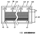
次に、図9〜図11を用いて、食器位置調節部材100を支持体22、23、33、34に装着して、先頭に位置する皿37の表面側と最後尾に位置する皿37の裏面側を規制する位置間の距離を調節可能として複数の皿37を収納した例を説明する。食器位置調節部材100は、例えばシリコンゴム等の弾性を有する材料で構成し、挿入口100aを支持体22、23、33、34の円周方向からに挿入して軸孔100b部分で保持させて装着する。食器位置調節部材100が弾性を有することから、支持体22、23、33、34に着脱自在に装着することができるとともに、支持体22、23、33、34の軸長方向にも移動させることができるように構成しているものである。   Next, using FIG. 9 to FIG. 11, the tableware position adjusting member 100 is attached to the supports 22, 23, 33, 34, and the surface side of the plate 37 positioned at the top and the plate 37 positioned at the tail An example will be described in which a plurality of dishes 37 are accommodated so that the distance between positions for regulating the back surface side can be adjusted. The tableware position adjustment member 100 is made of an elastic material such as silicon rubber, for example, and the insertion port 100a is inserted from the circumferential direction of the supports 22, 23, 33, and 34 and is held by the shaft hole 100b portion. Installing. Since the tableware position adjusting member 100 has elasticity, the tableware position adjusting member 100 can be detachably attached to the supports 22, 23, 33, and 34, and can also be moved in the axial direction of the supports 22, 23, 33, and 34. It is configured to be able to.

学校給食に用いる収納具14は、前記したように皿37の収納数を20〜40個とするが、この収納数の範囲において、例えば定格の収納数を20個、25個、30個、35個、40個とした収納具14を用意し、クラス別の生徒数に応じて定格の収納数の異なる収納具14を組み合わせて用いる。前記のように収納具14を組み合わせて用いるが、クラスの生徒数の若干の変動によって、皿37の収納数も変動する場合がある。皿37の収納数を例えば20個を収納具14の定格の収納数として設定した場合、生徒数が減少したときには、収納具14に収納する皿37の収納数も減少し、前記した所定のスペース(L2)が大きくななる。これによって収納具14を水平方向にしたときに複数の皿37の傾斜角度が大きくなり収納具14内での複数の皿37の姿勢がばらつくとともに不安定となって、後述する洗浄時に互いに隣り合う皿37を洗浄水によって確実に離間させることができなくなることが生じる。   As described above, the storage device 14 used for school lunches has a storage capacity of 20 to 40 dishes 37. Within this storage capacity range, for example, the rated storage capacity is 20, 25, 30, 35. The storage tools 14 having 40 pieces are prepared, and the storage tools 14 having different rated storage numbers are used in combination according to the number of students for each class. As described above, the storage device 14 is used in combination, but the storage number of the dishes 37 may also vary depending on the slight variation in the number of students in the class. For example, when the number of stored dishes 37 is set to 20 as the rated number of stored containers 14, when the number of students decreases, the number of stored dishes 37 stored in the storage apparatus 14 also decreases. (L2) becomes large. As a result, the inclination angle of the plurality of dishes 37 increases when the storage tool 14 is set in the horizontal direction, and the postures of the plurality of dishes 37 in the storage tool 14 vary and become unstable, and are adjacent to each other during cleaning, which will be described later. The dish 37 cannot be reliably separated by the washing water.

このため、例として図9、図10に示すように、20個を定格の皿37の収納数として設定した収納具14内に、例えば収納数が2個減少したときに食器位置調節部材100を用いて、前記所定のスペース(L2)を最適寸法に調節するものである。皿37の周端部37cの2個分の間隔(ピッチ)に相当する位置に、食器位置調節部材100を支持体22、23、33、34に装着し、図6に示す20個を定格の皿37の収納数として収納した場合と所定のスペース(L2)を同一に調節する。この場合は食器位置調節部材100が先頭に位置する皿37の表面側37aの位置規制部材17、28の機能を備えることになる。なお(L1−2N)は、収納数が2個減少したときの積み重ねた皿37の先頭(最上部)に位置する皿37の表面37aと、最後尾(最下部)位置する皿37の裏面37bとの全長を示す。 For this reason, as shown in FIG. 9 and FIG. 10 as an example, the tableware position adjusting member 100 is placed in the storage device 14 in which 20 is set as the storage number of the rated dishes 37, for example, when the storage number decreases by two. Used to adjust the predetermined space (L2) to an optimum dimension. The tableware position adjusting member 100 is mounted on the support bodies 22, 23, 33, and 34 at positions corresponding to the interval (pitch) of the two peripheral end portions 37c of the plate 37, and the 20 pieces shown in FIG. The predetermined space (L2) is adjusted in the same manner as when the number of plates 37 is stored. In this case, the tableware position adjusting member 100 has the functions of the position regulating members 17 and 28 on the surface side 37a of the plate 37 at the head. Note that (L1-2N) indicates the front surface 37a of the plate 37 positioned at the top (uppermost portion) of the stacked plates 37 and the rear surface 37b of the plate 37 positioned at the rearmost (lowermost) position when the number of stored items decreases by two. And the full length.

次に、図12〜15に基づいて、基本的な洗浄の動作、作用および洗浄における食器の姿勢状態変化を説明する。なお収納具に複数の食器37を収納した状態は、先ず図6、図7に示したものをベースとして説明する。また図中において、Wは噴射された洗浄水の流れを示す。   Next, based on FIGS. 12-15, the fundamental washing | cleaning operation | movement, an effect | action, and the posture state change of the tableware in washing | cleaning are demonstrated. In addition, the state which accommodated the several tableware 37 in the storage tool is demonstrated based on what was first shown in FIG. 6, FIG. Moreover, in the figure, W shows the flow of the jetted washing water.

図12(a)は、移動方向における先頭に位置する収納具14に収納された皿37の表面37aの洗浄状態を示す。先頭に位置する皿37の表面37aに対し、ノズル10、11から間隔(S4)部分に洗浄水が噴射される。これによってノズル10、11からの洗浄水が皿37の表面37a部において衝突流となって拡散し汚れを除去するものである。特に皿37の表面37a部と枠17、28との間で洗浄水が跳ね返りながら表面37a部に当たることによって汚れを確実に除去するものである。   Fig.12 (a) shows the washing | cleaning state of the surface 37a of the dish 37 accommodated in the storage tool 14 located in the head in the moving direction. Washing water is sprayed from the nozzles 10 and 11 to the space (S4) portion on the front surface 37a of the dish 37 located at the head. As a result, the washing water from the nozzles 10 and 11 becomes a collision flow on the surface 37a of the dish 37 and diffuses to remove dirt. In particular, the cleaning water splashes between the surface 37a portion of the dish 37 and the frames 17 and 28 and strikes the surface 37a portion to reliably remove the dirt.

図12(a)の状態においては、複数の食器37は所定角度に傾斜した姿勢であるが、ノズル10、11からの洗浄水が皿37の表面37aへの動圧を与え、また皿37の表面37a部と枠17、28との間隔を上方から下方へ洗浄水が流動することによって、図12(b)に示すように、皿37の表面37aの下部が枠17、28から離れて離間し、先頭から最後尾に位置する複数の皿37が所定角度に傾斜した姿勢から略鉛直姿勢に変化する。さらに皿37の表面37a部と枠17、28との間隔を上方から下方へ洗浄水が流動し、皿37の表面37aの汚れを除去するものである。   In the state of FIG. 12A, the plurality of dishes 37 are inclined at a predetermined angle, but the washing water from the nozzles 10 and 11 gives dynamic pressure to the surface 37 a of the dish 37, As the washing water flows from above to below the space between the surface 37a and the frames 17, 28, the lower portion of the surface 37a of the dish 37 is separated from the frames 17, 28 as shown in FIG. Then, the plurality of dishes 37 positioned from the head to the tail changes from a posture inclined at a predetermined angle to a substantially vertical posture. Further, the washing water flows from the upper side to the lower side of the space between the surface 37a portion of the plate 37 and the frames 17 and 28, thereby removing dirt on the surface 37a of the plate 37.

図13(a)は、図12(b)の状態から固定配置したノズル10、11に対し、コンベア2により収納具14が移動して、洗浄水が先頭に位置する皿37の周端部37cに当たっている状態を示す。ノズル10、11から噴射する洗浄水は、所定の幅を有し、また洗浄水はその中央部の流速が外周部の流速よりも早い速度分布となっている。さらに周端部37cの厚さ(幅)は小さく、所定の曲率を有する構造となっている。これらによって洗浄水は皿37の周端部37cに当たるとき周端部37cの両側に分流され、この分流量の割合は収納具14の移動によりごく短時間に変化することになる。なおノズル10、11から噴射する洗浄水の収納具14の移動方向における幅は細く絞る必要はなく、例えば互いに隣り合う皿37の周端部37のピッチ寸法程度でよい。   FIG. 13A shows the peripheral end portion 37c of the dish 37 in which the storage tool 14 is moved by the conveyor 2 with respect to the nozzles 10 and 11 fixedly arranged from the state of FIG. Indicates the state of hitting. The washing water sprayed from the nozzles 10 and 11 has a predetermined width, and the washing water has a velocity distribution in which the flow velocity at the central portion is faster than the flow velocity at the outer peripheral portion. Furthermore, the thickness (width) of the peripheral end portion 37c is small and has a structure having a predetermined curvature. As a result, the washing water is diverted to both sides of the peripheral end portion 37 c when it hits the peripheral end portion 37 c of the dish 37, and the proportion of the flow rate changes in a very short time due to the movement of the storage tool 14. The width in the moving direction of the storage device 14 for the cleaning water sprayed from the nozzles 10 and 11 does not need to be narrowed, and may be, for example, about the pitch dimension of the peripheral end portions 37 of the plates 37 adjacent to each other.

したがって、収納具14の移動により先頭に位置する皿37の周端部37cから枠17、28側への洗浄水の分流成分の量が、先頭に位置する皿37の周端部37cから隣り合う二番目の皿37側への洗浄水の分流成分の量よりも多いときは、皿37の表面37a部と枠17、28は図12(b)に示す離間した状態にある。   Therefore, the amount of the diversion component of the washing water from the peripheral edge 37c of the tray 37 positioned at the head to the frames 17 and 28 due to the movement of the storage tool 14 is adjacent to the peripheral edge 37c of the tray 37 positioned at the head. When the amount of the diversion component of the washing water to the second dish 37 side is larger, the surface 37a portion of the dish 37 and the frames 17, 28 are in a separated state as shown in FIG.

さらに、収納具14の移動により先頭に位置する皿37の周端部37cから隣り合う二番目の皿37側への洗浄水の分流成分の量が、先頭に位置する皿37の周端部37cから枠17、28側への洗浄水の分流成分の量よりも多くなると、上方側の周端部37cの間隔(S3)に入り込んだ洗浄水の動圧および静圧が、先頭に位置する皿37の裏面37bおよび二番目の皿37の表面37aに作用してこれらを押し広げ、図13(b)に示すように先頭に位置する皿37は、枠17、28側へ支持体22、23、33、34を周端部37cが滑って移動して枠17、28へ接触し、同時に先頭に位置する皿37と隣り合う二番目の皿37とが接触した状態から離れて離間する。   Furthermore, the amount of the diversion component of the washing water from the peripheral end portion 37c of the dish 37 positioned at the head to the adjacent second dish 37 side by the movement of the storage tool 14 is the peripheral edge portion 37c of the dish 37 positioned at the head. If the amount of the diversion component of the washing water from the frame 17 to the frame 17 or 28 becomes larger, the dynamic pressure and static pressure of the washing water that has entered the interval (S3) between the upper peripheral end portions 37c are located at the top. It acts on the rear surface 37b of the plate 37 and the surface 37a of the second plate 37 to spread them, and the plate 37 located at the head as shown in FIG. , 33 and 34, the peripheral end 37c slides and contacts the frames 17 and 28. At the same time, the plate 37 located at the head and the second plate 37 adjacent to each other are separated from each other.

前記離間した間隔内を洗浄水が上部から下部方向および上部から横方向に流動し、先頭に位置する食器37の裏面37bおよび二番目の食器37の表面37aの汚れを除去して洗浄するものである。洗浄水が離間した間隔内を流動するとき、食器37の表面37aおよび裏面37bの汚れを確実に除去するとともに、離間した間隔の形成を保持することができる。   Washing water flows from the upper part to the lower part and from the upper part to the lateral part in the spaced intervals, and the dirt on the back surface 37b of the tableware 37 located at the top and the surface 37a of the second tableware 37 is removed and washed. is there. When the cleaning water flows in the spaced intervals, the dirt on the front surface 37a and the back surface 37b of the tableware 37 can be surely removed and the formation of the spaced intervals can be maintained.

前記したように、分流量の割合は収納具14の移動によりごく短時間に変化することから、図13(a)から図13(b)に示す状態の移行はほぼ瞬時に行われ、収納具14に収納した複数の皿37は略鉛直姿勢を維持したままの状態となる。図13(b)に示す状態において、洗浄水の流動により先頭に位置する皿37の裏面37bと隣り合う二番目の皿37の表面37aの汚れを除去するものである。   As described above, since the ratio of the partial flow rate changes in a very short time due to the movement of the storage device 14, the transition from the state shown in FIG. 13 (a) to FIG. 13 (b) is performed almost instantaneously. The plurality of dishes 37 stored in 14 are maintained in a substantially vertical posture. In the state shown in FIG. 13B, dirt on the surface 37a of the second dish 37 adjacent to the back surface 37b of the dish 37 positioned at the head is removed by the flow of the washing water.

図13(a)、(b)に示す状態において、収納具14に収納した複数の皿37は略鉛直姿勢を維持したままの状態となることから、所定角度(θ3)傾斜して収納した状態での上方側の周端部37cの間隔(S3)は、皿37を鉛直方向に積み重ねて収納具14に収納したときの周端部37cの間隔(S1)とほぼ同一となる。これによって互いに隣り合う皿37の上方側の周端部37cの間隔が広くなり、洗浄水がより互いに隣り合う皿37の周端部37cの間隔に入りやすくなる。   In the state shown in FIGS. 13A and 13B, the plurality of dishes 37 stored in the storage device 14 is maintained in a substantially vertical posture, and is stored at a predetermined angle (θ3). The interval (S3) between the upper peripheral end portions 37c is substantially the same as the interval (S1) between the peripheral end portions 37c when the plates 37 are stacked in the vertical direction and stored in the storage tool 14. As a result, the interval between the peripheral end portions 37c on the upper side of the plates 37 adjacent to each other is widened, and the cleaning water is more likely to enter the interval between the peripheral end portions 37c of the plates 37 adjacent to each other.

図14(a)は、図13(b)の状態から固定配置したノズル10、11に対し、コンベア2により収納具14が移動して、洗浄水が二番目に位置する皿37の周端部37cに当たっている状態を示す。前記図13(a)、図13(b)における状態変化と同様に、
収納具14の移動により二番目に位置する皿37の周端部37cから先頭に位置する皿37側への洗浄水の分流成分の量が、二番目から隣り合う三番目の皿37側への洗浄水の分流成分の量よりも多いときは、先頭に位置する皿37の裏面37bと二番目に位置する皿37の表面37aは図13(b)に示す離間した状態にある。
FIG. 14A shows the peripheral edge of the dish 37 where the storage tool 14 is moved by the conveyor 2 relative to the nozzles 10 and 11 fixedly arranged from the state of FIG. The state which hits 37c is shown. Similar to the state change in FIG. 13 (a) and FIG. 13 (b),
The amount of the diversion component of the wash water from the peripheral end portion 37c of the second dish 37 to the first dish 37 side by the movement of the storage tool 14 is changed from the second to the third dish 37 side adjacent to the second dish 37. When it is larger than the amount of the diversion component of the washing water, the back surface 37b of the dish 37 located at the top and the surface 37a of the dish 37 located second are in a separated state as shown in FIG.

さらに、収納具14の移動により二番目に位置する皿37の周端部37cから隣り合う三番目の皿37側への洗浄水の分流成分の量が、二番目に位置する皿37の周端部37cから先頭に位置する皿37側への洗浄水の分流成分の量よりも多くなると、図14(b)に示すように二番目に位置する皿37は先頭に位置する皿37側へ支持体22、23、33、34を滑って移動して先頭に位置する皿37へ接触し、同時に二番目に位置する皿37と隣り合う三番目の皿37とが接触した状態から離れて離間する。   Furthermore, the amount of the diversion component of the washing water from the peripheral end portion 37c of the second dish 37 to the adjacent third dish 37 side by the movement of the storage tool 14 is the peripheral edge of the second dish 37. When the amount of the diversion component of the washing water from the portion 37c to the top plate 37 is increased, the second plate 37 is supported to the top plate 37 as shown in FIG. 14 (b). The body 22, 23, 33, 34 is slid and moved to contact the top plate 37, and at the same time, the second plate 37 and the adjacent third plate 37 are separated from the contacted state. .

前記したように、分流量の割合は収納具14の移動によりごく短時間に変化することから、図14(a)から図14(b)に示す状態の移行はほぼ瞬時に行われ、収納具14に収納した複数の皿37は略鉛直姿勢を維持したままの状態となる。図14(b)に示す状態において、洗浄水の流動により二番目に位置する皿37の裏面37bと隣り合う三番目の皿37の表面37aの汚れを除去するものである。これ以降、収納具14の移動により前記した同様の動作、作用を繰り返し、収納具14に収納した食器37の洗浄を順次行うものである。   As described above, since the ratio of the partial flow rate changes in a very short time due to the movement of the storage device 14, the transition from the state shown in FIG. 14 (a) to FIG. 14 (b) is performed almost instantaneously. The plurality of dishes 37 stored in 14 are maintained in a substantially vertical posture. In the state shown in FIG. 14B, the dirt on the surface 37a of the third dish 37 adjacent to the back surface 37b of the second dish 37 is removed by the flow of the washing water. Thereafter, the same operation and action as described above are repeated by moving the storage tool 14, and the tableware 37 stored in the storage tool 14 is sequentially washed.

図15(a)は、収納具14の移動により、ノズル10、11からの洗浄水が、最後尾に位置する皿37の裏面37bの位置に移動したときの洗浄状態を示す。ノズル10、11の洗浄水は、最後尾に位置する皿37の裏面37bとベース板16、27との間隔(S6)に入り、収納具14のベース板16、27の面と最後尾に位置する皿37の裏面37bとの間で衝突を繰り返し最後尾に位置する皿37の裏面37bの汚れを除去し洗浄する。収納具14に収納した複数の皿37は、最後尾に位置する皿37の裏面37bが洗浄水に押されていることにより略鉛直方向の姿勢となっているものである。   FIG. 15A shows a cleaning state when the cleaning water from the nozzles 10 and 11 is moved to the position of the rear surface 37b of the dish 37 located at the end by the movement of the storage tool 14. FIG. The cleaning water of the nozzles 10 and 11 enters the space (S6) between the back surface 37b of the plate 37 located at the tail and the base plates 16 and 27, and is located at the surface and the tail of the base plates 16 and 27 of the storage device 14. The rear surface 37b of the plate 37 located at the rear end is removed and cleaned by repeatedly colliding with the back surface 37b of the plate 37. The plurality of dishes 37 stored in the storage device 14 is in a substantially vertical orientation when the back surface 37b of the dish 37 located at the rearmost end is pushed by the cleaning water.

一般的に食器の表面よりも食器の裏面の汚れは少ないが、前記作用により最後尾に位置する皿37の裏面37bの汚れを確実に除去するものである。なお図12〜15に示した洗浄動作時において、収納具14自体もノズル10、11から噴射した洗浄水および皿37からの洗浄水の流動によって洗浄されるものである。   In general, the back surface of the tableware is less dirty than the surface of the tableware, but the above operation reliably removes the stain on the back surface 37b of the plate 37 located at the tail. In the cleaning operation shown in FIGS. 12 to 15, the container 14 itself is also cleaned by the flow of the cleaning water sprayed from the nozzles 10 and 11 and the cleaning water from the dish 37.

図15(b)は、図15(a)の状態から収納具14の移動により、ノズル10、11からの洗浄水が収納具14のベース板16、27より外れた位置に移動したときの洗浄状態を示す。このときはノズル10、11からの洗浄水が複数の皿37に当たらないので、図7に示すように複数の皿37は収納時と同様に所定角度(θ3)に傾斜した状態に戻ることになる。   FIG. 15B shows the cleaning when the cleaning water from the nozzles 10 and 11 is moved to a position away from the base plates 16 and 27 of the storage tool 14 by the movement of the storage tool 14 from the state of FIG. Indicates the state. At this time, since the washing water from the nozzles 10 and 11 does not hit the plurality of dishes 37, the plurality of dishes 37 return to a state inclined at a predetermined angle (θ3) as in the case of storage as shown in FIG. Become.

以上のように、図12〜15に示した洗浄動作を、荒洗浄ゾーン7a、中間洗浄ゾーン7b、仕上げ洗浄ゾーン7cにおいて行い、収納具14とともに収納した皿37の洗浄を完了する。洗浄を終了した皿37は、収納具14に収納したまま、次工程で例えば乾燥、殺菌等を行い保管されるものである。なお一つの洗浄ゾーンにおいて、収納具14の一方向の移動により図12〜15に示した洗浄動作を複数回行うようにしてもよく、必要に応じて選択する。   As described above, the cleaning operation shown in FIGS. 12 to 15 is performed in the rough cleaning zone 7a, the intermediate cleaning zone 7b, and the final cleaning zone 7c, and the cleaning of the dish 37 stored together with the storage tool 14 is completed. The dish 37 that has been cleaned is stored in the storage tool 14 by being dried, sterilized, or the like in the next step. In one cleaning zone, the cleaning operation shown in FIGS. 12 to 15 may be performed a plurality of times by movement in one direction of the container 14 and is selected as necessary.

次に、図9〜11に示した食器位置調節部材100を設けて収納具に複数の皿を収納した場合の洗浄動作を図16により説明する。   Next, a cleaning operation when the tableware position adjusting member 100 shown in FIGS. 9 to 11 is provided and a plurality of dishes are stored in the storage tool will be described with reference to FIG.

図16(a)は、移動方向における先頭に位置する収納具14に収納された皿37の表面37aの洗浄状態を示す。先頭に位置する皿37の表面37aに対し、ノズル10、11から洗浄水が噴射される。これによってノズル10、11からの洗浄水が皿37の表面37a部において衝突流となって拡散し汚れを除去するものである。特に皿37の表面37a部と枠17、28との間で洗浄水が跳ね返りながら表面37a部に当たることによって汚れを確実に除去するものである。   FIG. 16A shows a cleaning state of the surface 37a of the dish 37 stored in the storage tool 14 located at the head in the moving direction. Washing water is sprayed from the nozzles 10 and 11 to the surface 37a of the dish 37 located at the head. As a result, the washing water from the nozzles 10 and 11 becomes a collision flow on the surface 37a of the dish 37 and diffuses to remove dirt. In particular, the cleaning water splashes between the surface 37a portion of the dish 37 and the frames 17 and 28 and strikes the surface 37a portion to reliably remove the dirt.

図16(a)の状態においては、複数の皿37は所定角度に傾斜した姿勢であるが、ノズル10、11からの洗浄水が皿37の表面37aへの動圧を与え、また皿37の表面37a部と枠17、28との間隔を上方から下方へ洗浄水が流動することによって、図16(b)に示すように、皿37の表面37aの下部が食器位置調節部材100から離れて離間し、先頭から最後尾に位置する複数の皿37が所定角度に傾斜した姿勢から略鉛直姿勢に変化する。さらに皿37の表面37a部と枠17、28との間隔を上方から下方へ洗浄水が流動し、皿37の表面37aの汚れを除去するものである。以降、図13〜図15に示す洗浄時における皿37の姿勢状態変化を示す図と同様であるので説明を省略する。   In the state of FIG. 16A, the plurality of dishes 37 are inclined at a predetermined angle, but the washing water from the nozzles 10 and 11 gives dynamic pressure to the surface 37 a of the dish 37, As the washing water flows from above to below the space between the surface 37a and the frames 17, 28, the lower portion of the surface 37a of the dish 37 is separated from the tableware position adjusting member 100 as shown in FIG. The plurality of dishes 37 that are spaced apart and located from the head to the tail change from a posture inclined at a predetermined angle to a substantially vertical posture. Further, the washing water flows from the upper side to the lower side of the space between the surface 37a portion of the plate 37 and the frames 17 and 28, thereby removing dirt on the surface 37a of the plate 37. Hereafter, since it is the same as the figure which shows the attitude | position state change of the plate | plate 37 at the time of washing | cleaning shown in FIGS. 13-15, description is abbreviate | omitted.

また本実施例においては、断面が円形である棒状の支持体22、23、33、34と皿37の周端部37cとはほぼ点接触となり滑り抵抗を減少させることができる。支持体22、23および33、34は、平滑性のよい加工表面または少なくとも表面が樹脂等であることが好ましく、この場合には支持体22、23および33、34と皿37の周端部37cとの滑り性を良くして皿37の移動をスムーズにし、洗浄時における互いに隣り合う皿37の離間動作と姿勢変化をより確実に行うことができる。   Further, in this embodiment, the rod-like supports 22, 23, 33, 34 having a circular cross section and the peripheral end portion 37c of the plate 37 are almost in point contact, and slip resistance can be reduced. The supports 22, 23 and 33, 34 are preferably processed surfaces having good smoothness, or at least the surface thereof is preferably a resin or the like. In this case, the supports 22, 23, 33, 34 and the peripheral edge 37c of the dish 37 are used. And the movement of the plate 37 can be made smooth, and the separating operation and the posture change of the plates 37 adjacent to each other during cleaning can be more reliably performed.

また、収納具14の支持体22、23および33、34の数、断面形状、配置位置等は、実施例に限定されるものではなく、食器の形状、大きさ、質量、材質等によって、洗浄時の食器の傾斜姿勢および傾斜姿勢から鉛直方向への移動の安定性を考慮して最適条件に設定すればよい。実施例においては、収納部15を下にして収納具14を水平方向(横方向)の姿勢にして洗浄を行うので、複数の食器の質量を収納部15の支持体22、23が受けて支持することになる。したがって収納部15の支持体22、23の数を保持部26の支持体33、34の数よりも多くしてもよく、この場合には安定性をより向上させることができる。   Further, the number, the cross-sectional shape, the arrangement position, and the like of the supports 22, 23 and 33, 34 of the storage device 14 are not limited to the embodiment, and the cleaning is performed according to the shape, size, mass, material, etc. of the tableware. The optimal condition may be set in consideration of the tilting posture of the tableware and the stability of the movement from the tilting posture to the vertical direction. In the embodiment, since the cleaning is performed with the storage unit 15 facing down and the storage device 14 in the horizontal direction (lateral direction), the supports 22 and 23 of the storage unit 15 receive and support the mass of a plurality of dishes. Will do. Therefore, the number of the supports 22 and 23 of the storage unit 15 may be larger than the number of the supports 33 and 34 of the holding unit 26, and in this case, the stability can be further improved.

本発明の実施例の収納具14は、複数の皿37の周端部37cが支持体22、23、33、34を自由に滑って重ね方向に沿って移動自在に支持するとともに、先頭に位置する皿37の表面37a側と最後尾に位置する皿37の裏面37b側のみの位置を規制して、表面37a側と裏面37b側を水平方向に重ねた複数の皿37を、重ね方向に沿った移動および鉛直方向の姿勢変化を所定範囲内で自在となるように収納するものである。   In the storage device 14 according to the embodiment of the present invention, the peripheral end portions 37c of the plurality of dishes 37 freely slide the support bodies 22, 23, 33, and 34 so as to be movable along the overlapping direction, and are positioned at the top. A plurality of dishes 37 in which the front surface 37a side and the back surface 37b side are overlapped in the horizontal direction are regulated along the stacking direction by restricting the positions of only the front surface 37a side and the rear surface 37b side of the last dish 37. The movement and vertical posture change are accommodated within a predetermined range.

これによって、従来のように個々の皿37の周端部を支持する必要がなく、寸法にばらつきのある皿37、外縁同士のピッチが小さく近接した皿37、喫食後の残飯、肉片等の固形物が付着した皿37を、積み重ねてそのまま収納具に挿入、収納することができる。また複数の皿37の個々の嵌め込み具合の確認も不要となり、複数の皿37の収納および取り出しを極めて容易にして収納性を向上させることができる。   As a result, it is not necessary to support the peripheral end of each dish 37 as in the prior art, and the dish 37 with variability in dimensions, the dish 37 in which the pitch between the outer edges is small and close, solid food after eating, meat pieces, etc. The dishes 37 to which the objects are attached can be stacked and inserted into the storage device as they are. In addition, it is not necessary to check the degree of fitting of the plurality of dishes 37, and the storage and take-out of the plurality of dishes 37 can be made extremely easy and the storage property can be improved.

さらに、従来は個々の皿37の周端部を支持するため、支持部材による皿37へ応力がかかることがあり、収納および取り出し、持ち運び、車両による運搬等のときに皿37を破損する恐れがあった。これに対して本発明の収納具は、個々の皿37の周端部を支持する必要がないので前記のような破損を生じることがない。   Further, conventionally, since the peripheral edge of each plate 37 is supported, stress may be applied to the plate 37 by the support member, and the plate 37 may be damaged during storage, removal, carrying, transportation by a vehicle, and the like. there were. On the other hand, since the storage device of the present invention does not need to support the peripheral ends of the individual dishes 37, the above-described damage does not occur.

また、積み重ねた皿37の全長に対して所定スペースだけ与えて収納すればよく、複数の皿37をコンパクトに収納して、収納具自体の小型化、軽量化を図ることができる。さらに構造の簡素化により、収納具に収納した複数の皿37へ噴射する洗浄水の流れに対して妨げとなる構成要素が少なく、複数の皿37の洗浄を確実に行うことができる。また収納具自体の洗浄も確実に行うことができるとともに、複数の皿37の汚れ成分が引っかかり収納具に残ってしまうこともない。このように収納具の構成を簡素化するとともに皿37の収納性を向上させることができる。   Further, only a predetermined space may be provided and stored with respect to the total length of the stacked dishes 37, and the plurality of dishes 37 can be stored in a compact manner, so that the storage tool itself can be reduced in size and weight. Furthermore, due to the simplification of the structure, there are few components that obstruct the flow of the cleaning water sprayed to the plurality of dishes 37 stored in the storage tool, and the plurality of dishes 37 can be reliably cleaned. In addition, the storage device itself can be reliably cleaned, and the dirt component of the plurality of dishes 37 is caught and does not remain in the storage device. Thus, the structure of the storage tool can be simplified and the storage performance of the dish 37 can be improved.

さらに、皿37の収納数の変動に対して、簡単な手段によって先頭に位置する皿37の表面側と最後尾に位置する皿37の裏面側を規制する位置間の距離を調節可能としたことによって、皿37の収納数が変動しても皿37の姿勢を安定化させることができる。また収納具の共用化をより図ることができ、収納数別に用意する収納具の種類を削減することができる。   Furthermore, the distance between the positions for regulating the front surface side of the plate 37 located at the head and the back surface side of the plate 37 located at the rearmost position can be adjusted by simple means with respect to fluctuations in the number of plates 37 stored. Thus, the posture of the plate 37 can be stabilized even if the number of plates 37 stored varies. Further, the storage tools can be shared more and the types of storage tools prepared according to the number of storage can be reduced.

また、複数の皿37の重ね方向に食器位置調節部材100を設けて、先頭に位置する皿37の表面側と最後尾に位置する皿37の裏面側を規制する位置間の距離を調節可能としたことによって、皿37の収納数の変動に対して、収納具14全体の変更の必要がなく柔軟に対応することができる。   Further, the tableware position adjusting member 100 is provided in the stacking direction of the plurality of dishes 37, and the distance between the positions for regulating the front surface side of the dish 37 located at the head and the back surface side of the dish 37 located at the rearmost can be adjusted. As a result, it is possible to flexibly cope with the change in the number of the dishes 37 stored without the need to change the entire storage tool 14.

また、食器位置調節部材100を支持体22、23、33、34に備えたことによって、食器位置調節部材を簡単に装着することができる。   Moreover, by providing the tableware position adjusting member 100 on the supports 22, 23, 33, 34, the tableware position adjusting member can be easily mounted.

さらに、食器位置調節部材100を複数の皿37を重ね方向に移動可能としたことによって、皿37の収納数のより多くの変動に対応することができる。また、食器位置調節部材100を着脱自在としたことによって、食器位置調節部材100の必要性に応じて簡単に対応することができる。   Furthermore, by allowing the tableware position adjusting member 100 to move the plurality of dishes 37 in the stacking direction, it is possible to cope with more fluctuations in the number of dishes 37 stored. Moreover, by making the tableware position adjusting member 100 detachable, it is possible to easily cope with the necessity of the tableware position adjusting member 100.

また、収納具14を水平方向(横方向)にした際に、皿37の重心が皿37の裏面37b側に位置することによって、複数の皿37は、裏面37b側を下方として周端部37cが支持体22、23、33、34を滑って、複数の皿37は互いにその一部が接触し、折り重なるようにして同方向に所定角度(θ3)に傾斜した姿勢となるものである。このように個々の皿37を支持し、この支持機構を操作して複数の皿37を傾斜させる必要がなく、収納具14を水平方向にするだけで複数の皿37が傾斜した姿勢となるので、洗浄時における操作作業を簡素化することができる。さらに複数の皿37の姿勢を安定化させた状態で洗浄装置に投入、搬送することができる。   Further, when the storage tool 14 is set in the horizontal direction (lateral direction), the center of gravity of the dish 37 is positioned on the back surface 37b side of the dish 37, so that the plurality of dishes 37 have the peripheral end portion 37c with the back surface 37b side downward. Slides on the supports 22, 23, 33, and 34, and the plurality of dishes 37 are in contact with each other and folded in a predetermined angle (θ3) in the same direction so as to overlap each other. Thus, it is not necessary to support the individual dishes 37 and operate the support mechanism to incline the plurality of dishes 37, and the plurality of dishes 37 are inclined only by placing the storage device 14 in the horizontal direction. The operation work at the time of cleaning can be simplified. Further, the plurality of dishes 37 can be charged and transported to the cleaning device in a stabilized state.

また、互いに隣り合う皿37の下方側の周端部37cの間隔を、上方側の周端部37cの間隔よりも広くなるようにして複数の皿37を収納する。これによって複数の皿37の姿勢をより安定化させた状態で洗浄装置に投入、搬送することができる。また洗浄後に保管する際、皿37の表面37a側と裏面37b側に付着した洗浄水が流出しやすく乾燥をより早めることができる。   Further, the plurality of dishes 37 are accommodated such that the interval between the lower peripheral end portions 37c of the adjacent dishes 37 is larger than the interval between the upper peripheral end portions 37c. As a result, the plurality of dishes 37 can be charged and transported to the cleaning device in a more stabilized state. Moreover, when storing after washing | cleaning, the washing water adhering to the surface 37a side and the back surface 37b side of the dish 37 tends to flow out, and can dry more quickly.

さらに、本発明の実施例の洗浄方法は、表面37a側と裏面37b側を水平方向に重ねた複数の食器である皿37の周端部37cを重ね方向に沿って複数の支持体22、23、33、34により支持するとともに、前記複数の皿37の内、先頭に位置する皿37の表面37a側と最後尾に位置する皿37の裏面37b側の位置を規制して、複数の皿37を重ね方向に沿った移動および姿勢変化を所定範囲内で自在となるようにして収納具14に収納し、前記収納具14に収納した複数の皿37の周端部にノズル10、11から洗浄水を重ね方向に沿って順次噴射し、前記ノズル10、11から噴射した洗浄水により、接触した互いに隣り合う皿37を離して離間させ、離間した間隔に流入した洗浄水の流動により複数の皿37の洗浄を順次行うものである。   Further, in the cleaning method of the embodiment of the present invention, the peripheral ends 37c of the plate 37, which is a plurality of tableware in which the front surface 37a side and the back surface 37b side are stacked in the horizontal direction, are arranged along the stacking direction. , 33, and 34, and among the plurality of dishes 37, the positions of the front surface 37 a side of the dish 37 positioned at the front and the back surface 37 b side of the dish 37 positioned at the rearmost are regulated, so that the plurality of dishes 37 Is stored in the storage device 14 so that movement and posture change along the overlapping direction can be freely performed within a predetermined range, and cleaning is performed from the nozzles 10 and 11 on the peripheral ends of the plurality of dishes 37 stored in the storage device 14. Water is sequentially sprayed along the overlapping direction, and the wash water sprayed from the nozzles 10 and 11 separates and separates the adjacent dishes 37 from each other. 37 washings in sequence It is intended.

前記したように、皿37の個々ごとに周端部37cを支持、拘束せずに所定範囲内で重ね方向の移動、姿勢変化を自由にして収納し、この周端部37cに重ね方向に沿って順次噴射する。これによって個々の皿37が洗浄水の流動に瞬時に追従して動いて揺動し、互いに隣り合う皿37が接触状態と離れた非接触状態を順次繰り返しながら離間する。前記洗浄水が離間した間隔内を流動するとき、汚れを確実に除去するとともに離間した間隔の形成を保持することがでる。 As described above, the peripheral end portion 37c is supported and restrained for each individual plate 37, and the movement and change of posture in the overlapping direction are freely stored within a predetermined range without being restrained, and the peripheral end portion 37c is moved along the overlapping direction. Inject sequentially. As a result, the individual dishes 37 immediately follow the flow of the washing water and swing, and the adjacent dishes 37 are separated while sequentially repeating the contact state and the non-contact state. When the washing water flows in the spaced intervals, it is possible to reliably remove dirt and to maintain the formation of the spaced intervals.

また、互いに隣り合う皿37が接触状態と離れた非接触状態を順次繰り返しながら、皿37が複数の支持体22、23、33、34に沿って移動、揺動し、さらに互いに隣り合う皿37が早い速度で接触しあうことになる。この移動および接触時の反動によって皿37に付着した汚れを除去することができ、残渣物の剥離を促進して洗浄性能をより高めることができる。さらに皿37の周端部37cが移動することによって周端部37c部分および収納具14自体の汚れも確実に除去することができる。   In addition, the plates 37 move and swing along the plurality of supports 22, 23, 33, 34 while sequentially repeating the contact state and the non-contact state in which the plates 37 are separated from each other, and the plates 37 that are adjacent to each other. Will contact each other at a high speed. By this movement and recoil at the time of contact, dirt attached to the dish 37 can be removed, and peeling of the residue can be promoted to improve the cleaning performance. Furthermore, the movement of the peripheral end portion 37c of the dish 37 can surely remove the contamination of the peripheral end portion 37c portion and the storage device 14 itself.

このように、個々の皿37の周端部37cの支持を不要とし、且つ互いに隣り合う皿37の間に洗浄水が流動するに必要な所定スペースを有して複数の皿37を収納具14に収納すればよく、収納具14を小型化することができる。これにより洗浄装置に、同時により多くの収納具14を投入して洗浄することができる。また前記したように互いに隣り合う皿37が瞬時に離間し、且つ汚れを確実に除去することができる。したがって、収納具にコンパクトに収納した皿37の汚れを確実にかつ効率的に除去することができるものである。   In this manner, the support of the peripheral end portion 37c of each dish 37 is not required, and the plurality of dishes 37 are stored in the storage device 14 with a predetermined space necessary for the washing water to flow between the dishes 37 adjacent to each other. The storage tool 14 can be reduced in size. As a result, a larger number of storage devices 14 can be put into the cleaning device at the same time for cleaning. Further, as described above, the plates 37 adjacent to each other can be instantaneously separated and the dirt can be reliably removed. Therefore, it is possible to reliably and efficiently remove the dirt on the dish 37 stored compactly in the storage tool.

また、本実施例においては、ノズル10、11から噴射した洗浄水により、所定角度傾斜した姿勢で収納した複数の皿37を略鉛直の姿勢に変化させて接触した互いに隣り合う皿37を離して離間させるものである。従来のように個々の皿37を支持して鉛直の姿勢にし、皿37の間に洗浄水を噴射して洗浄する場合には、洗浄水が皿37の表面37aおよび裏面37bに十分接触しないで流動するため、汚れを確実に除去できない恐れがある。これに対して、ノズル10、11からから噴射した洗浄水の流動により略鉛直の姿勢にまで変化させるもので、互いに隣り合う皿37を確実に離間させるとともに、洗浄水は、皿37の表面37aおよび裏面37bに必ず接触して流動することになり、さらに略鉛直の姿勢とすることで汚れ成分の落下を促進して汚れを確実に除去することができる。   Further, in the present embodiment, the wash dishes sprayed from the nozzles 10 and 11 change the plurality of dishes 37 stored in a posture inclined at a predetermined angle into a substantially vertical posture and separate the adjacent plates 37 that are in contact with each other. They are separated. When the individual dishes 37 are supported in a vertical posture as in the prior art, and cleaning water is sprayed between the dishes 37 for cleaning, the cleaning water does not sufficiently contact the front surface 37a and the back surface 37b of the dish 37. Since it flows, there is a possibility that dirt cannot be removed reliably. On the other hand, it is changed to a substantially vertical posture by the flow of the cleaning water sprayed from the nozzles 10 and 11, and the dishes 37 adjacent to each other are reliably separated from each other, and the cleaning water is supplied to the surface 37 a of the dish 37. In addition, the fluid flows in contact with the back surface 37b, and by adopting a substantially vertical posture, it is possible to promote the fall of the dirt component and remove the dirt reliably.

また、皿37の周端部37cに複数のノズル10、11より洗浄水を重ね方向に沿って噴射することによって、皿37の姿勢を安定させた状態で離間させるとともに、十分な洗浄水が離間した間隔に入り込み汚れを確実に除去することができる。さらに皿37の周端部37cの間隔に複数のノズル10、11から皿37の略中央部へ洗浄水を噴射することによって、複数のノズル10、11からの洗浄水が離間した間隔内で衝突流となって拡散し、洗浄水の噴射の無い周端部37c側から外方に排出する高速の洗浄水流を形成し、汚れを確実に除去することができる。なお本実施例においては、各洗浄ゾーンにおいてノズル数を2個としたがこれに限定するものではなく、皿37の外形寸法、形状等により互いに隣り合う皿37の離間および洗浄状態に応じて選択すればよい。   Further, by spraying the cleaning water from the plurality of nozzles 10 and 11 to the peripheral end portion 37c of the dish 37 along the overlapping direction, the dish 37 is separated in a stable state and sufficient washing water is separated. The dirt can be surely removed by entering the gap. Further, the cleaning water is sprayed from the plurality of nozzles 10 and 11 to the substantially central portion of the dish 37 at the interval of the peripheral end portion 37c of the dish 37, so that the cleaning water from the plurality of nozzles 10 and 11 collides within the interval. It is possible to form a high-speed washing water flow that diffuses as a flow and discharges outward from the peripheral end portion 37c side where no washing water is jetted, so that dirt can be reliably removed. In this embodiment, the number of nozzles is two in each cleaning zone. However, the number of nozzles is not limited to this, and it is selected according to the distance between adjacent dishes 37 and the cleaning state depending on the external dimensions and shape of the dishes 37. do it.

さらに、皿37の収納数の変動に対して、簡単な手段によって先頭に位置する皿37の表面側と最後尾に位置する皿37の裏面側を規制する位置間の距離を調節可能としたことによって、皿37の姿勢を安定化させることができる。したがって、皿37の収納数が変動しても互いに隣り合う皿37を確実に離間させることができ、汚れを確実に除去することができる。   Furthermore, the distance between the positions for regulating the front surface side of the plate 37 located at the head and the back surface side of the plate 37 located at the rearmost position can be adjusted by simple means with respect to fluctuations in the number of plates 37 stored. Thus, the posture of the dish 37 can be stabilized. Therefore, even if the number of stored dishes 37 varies, adjacent dishes 37 can be reliably separated from each other, and dirt can be reliably removed.

なお、所定スペース(L2)の寸法は、複数の皿37の鉛直面に対する傾斜角度(θ3)、互いに隣り合う皿37の洗浄時における必要な離間距離を考慮し、最適条件に設定すればよい。所定スペース(L2)に相当する離間距離は、洗浄水が互いに隣り合う皿37の表面37aおよび裏面37bの全面に流動する寸法でよく、大きな距離を必要としない。皿37の種類、形状、寸法、質量等によって異なるが、傾斜角度(θ3)は例えば5〜10度、離間距離は例えば10〜20ミリメートルに設定する。したがって皿37を収納具14にコンパクトに収納し、収納した状態のまま洗浄することができる。   The dimension of the predetermined space (L2) may be set to an optimum condition in consideration of an inclination angle (θ3) with respect to the vertical surface of the plurality of dishes 37 and a necessary separation distance when cleaning the dishes 37 adjacent to each other. The separation distance corresponding to the predetermined space (L2) may be a dimension in which the cleaning water flows over the entire surface 37a and back surface 37b of the plates 37 adjacent to each other, and does not require a large distance. Although depending on the type, shape, size, mass, and the like of the plate 37, the inclination angle (θ3) is set to 5 to 10 degrees, for example, and the separation distance is set to 10 to 20 millimeters, for example. Therefore, the dish 37 can be stored compactly in the storage tool 14 and washed while being stored.

また、収納具14の移動速度は、洗浄水の噴射量および噴射速度、互いに隣り合う皿37が離間して洗浄水が流動している時間と相関し、皿37の汚れが多い場合には移動速度をより遅くし、汚れが少ない場合には移動速度をより早くすればよく、状況に応じて設定する。通常収納具14の移動速度は例えば分速0.5〜1メートルに設定する。   Further, the moving speed of the storage device 14 correlates with the amount and speed of washing water jetting and the time during which the washing water flows while the adjacent dishes 37 are separated from each other. If the speed is made slower and if there is little dirt, the moving speed should be made faster and set according to the situation. The moving speed of the normal storage tool 14 is set to 0.5 to 1 meter per minute, for example.

なお、前記した洗浄状態において、洗浄水により複数の皿37を所定角度傾斜した姿勢から略鉛直姿勢に変化させたが、所定角度(θ3)傾斜した姿勢を若干鉛直方向に変化させ、傾斜した姿勢のまま、互いに隣り合う皿37を接触状態から非接触状態として離間させて洗浄水を流動させて洗浄を行うようにしてもよい。この場合の非接触状態における互いに隣り合う皿37の上方側の間隔は、例えば10ミリメートル以下と狭くなるが、この状態においてもノズル10、11からの洗浄水を皿37の上方側の周端部37cの間隔に入り込ませ、さらに皿37の下方側に抜けるようにして流動させて洗浄することができる。   In the above-described cleaning state, the plurality of dishes 37 were changed from the posture inclined at a predetermined angle by the cleaning water to the substantially vertical posture, but the posture inclined at the predetermined angle (θ3) was slightly changed to the vertical direction to incline the posture. Alternatively, the plates 37 adjacent to each other may be separated from the contact state to the non-contact state, and the cleaning water may be flowed to perform cleaning. In this case, the distance between the upper sides of the plates 37 adjacent to each other in a non-contact state is as narrow as, for example, 10 millimeters or less. It can be washed by flowing into the space 37c and further flowing downward from the dish 37.

前記した皿37の所定角度(θ3)傾斜した姿勢から鉛直方向への姿勢の変化角度は、例えばノズル10、11からの洗浄水の量、噴射速度、洗浄スペース7内での収納具14の移動速度等によって調節することができる。ノズル10、11からの洗浄水の量を減少させること、噴射速度を遅くすること、洗浄スペース7内での収納具14の移動速度をより早くすることのうち、少なくともいずれかを調節することによって、鉛直方向への姿勢の変化角度は小さくなる傾向となり、互いに隣り合う食器の上方側の離間した間隔も狭くなる。これは、食器の形状、質量および汚れの程度によって最適条件に設定すればよい。   The angle of change of the posture of the dish 37 from the posture inclined at a predetermined angle (θ3) to the vertical direction is, for example, the amount of washing water from the nozzles 10, 11, the jetting speed, and the movement of the container 14 within the washing space 7. Can be adjusted by speed etc. By adjusting at least one of reducing the amount of cleaning water from the nozzles 10 and 11, reducing the spraying speed, and increasing the moving speed of the storage tool 14 in the cleaning space 7. The change angle of the posture in the vertical direction tends to be small, and the spacing between the upper sides of the adjacent tableware is also narrowed. What is necessary is just to set this to optimal conditions with the shape of a tableware, mass, and the grade of dirt.

また皿37の所定角度(θ3)傾斜した姿勢から鉛直方向への姿勢の変化角度を少なくして傾斜したまま洗浄水を噴射する場合には、図7および図8に示すように、互いに隣り合う皿37の周端部37cの高さ方向に段差(S5)が形成されているとともに、ノズル10、11は鉛直面に対して所定角度(θ1)を有して設けていることによって、ノズル10、11から噴射された洗浄水は、段差(S5)部分に当たって捕捉され、皿37の上方側の周端部37cの間隔に入り込み易い状態となる。   Further, when the washing water is jetted while being inclined while reducing the change angle of the posture in the vertical direction from the posture inclined by the predetermined angle (θ3) of the plate 37, as shown in FIGS. 7 and 8, they are adjacent to each other. A step (S5) is formed in the height direction of the peripheral end portion 37c of the plate 37, and the nozzles 10 and 11 are provided with a predetermined angle (θ1) with respect to the vertical plane, whereby the nozzle 10 The washing water sprayed from 11 and 11 is caught by hitting the step (S5) portion, and easily enters the interval between the peripheral end portions 37c on the upper side of the plate 37.

前記した段差(S5)部分による洗浄水の捕捉作用により、傾斜した姿勢のまま複数の皿37を順次離間させて洗浄することができる。この場合には収納具14に収納した複数の皿37も傾斜した姿勢となっている。   Due to the action of trapping the washing water by the step (S5) described above, the plurality of dishes 37 can be sequentially separated and washed in the inclined posture. In this case, the plurality of dishes 37 stored in the storage tool 14 are also inclined.

なお、図示しないが、収納具14を一方向の移動から駆動手段により往復移動させて皿37の洗浄を行うか、または収納具14を固定し、駆動手段によりノズル10、11を往復移動させて皿37の洗浄を行うことによって、洗浄装置の小型化が可能となり、省スペース化を図ることができる。特に洗浄する皿37の個数の比較的少ない場合に最適である。   Although not shown, the container 14 is moved back and forth by a driving means from one direction to clean the dish 37, or the container 14 is fixed and the nozzles 10 and 11 are moved back and forth by the driving means. By washing the dish 37, it is possible to reduce the size of the washing apparatus and save space. This is particularly suitable when the number of dishes 37 to be cleaned is relatively small.

なお、丸形状の食器としてお椀があるが、収納具および洗浄方法は前記皿37と同様の構成、洗浄動作、作用、効果となるものである。   Although there is a bowl as a round tableware, the storage tool and the cleaning method have the same configuration, cleaning operation, action, and effect as the dish 37.

次に、食器である四角形状のトレイの洗浄方法について図17〜図29を参照しながら説明する。洗浄装置はトレイを収納した収納具以外は図1、図2に示したものと同様のものを用いるものである。なお四角形状の食器としては、仕切り皿もあるが洗浄方法としてはトレイとほぼ同様である。   Next, a method for cleaning a rectangular tray that is tableware will be described with reference to FIGS. The cleaning device is the same as that shown in FIGS. 1 and 2 except for the storage device storing the tray. In addition, although square dishes have a partition plate, the washing method is almost the same as that of the tray.

図17はトレイの収納具の概観斜視図、図18は図17の収納具の上面図、図19は複数のトレイを鉛直方向(縦方向)に積み重ねた状態を示す概観図、図20は鉛直方向に積み重ねたトレイを収納具に収納した状態を示す正面図、図21は収納具を鉛直方向から水平方向(横方向)に倒した状態におけるトレイの姿勢を示す図、図22はトレイの周端部の一部拡大図、図23は食器位置調節部材を設けて鉛直方向に積み重ねたトレイを収納具に収納した状態を示す正面図、図24は食器位置調節部材を設けて収納具を鉛直方向から水平方向に倒した状態におけるトレイの姿勢を示す図、図25〜28は食器位置調節部材を設けないで収納具に複数のトレイを収納した場合の洗浄時におけるトレイの姿勢状態変化を示す図、図29は食器位置調節部材を設けて収納具に複数のトレイを収納した場合の洗浄開始時におけるトレイの姿勢状態変化を示す図である。なお食器位置調節部材100は、図11の示すものと同一である。   17 is a schematic perspective view of the tray storage device, FIG. 18 is a top view of the storage device of FIG. 17, FIG. 19 is a general view showing a state in which a plurality of trays are stacked in the vertical direction (vertical direction), and FIG. 21 is a front view showing a state in which the trays stacked in the direction are stored in the storage device, FIG. 21 is a view showing the posture of the tray when the storage device is tilted from the vertical direction to the horizontal direction (lateral direction), and FIG. FIG. 23 is a front view showing a state in which trays stacked in the vertical direction with the tableware position adjusting member provided therein are stored in the storage device, and FIG. 24 is a table with the tableware position adjustment member provided in the vertical direction. The figure which shows the attitude | position of the tray in the state which fell in the horizontal direction from the direction, FIGS. 25-28 show the attitude | position state change of the tray at the time of washing | cleaning at the time of accommodating a several tray in an accommodating tool, without providing a tableware position adjustment member. Figure 29 shows tableware position It is a diagram illustrating the posture change of the tray at the cleaning start time in the case of accommodating a plurality of trays in the storage device by providing a section member. The tableware position adjusting member 100 is the same as that shown in FIG.

図17のトレイ51の収納具38の概観斜視図および図18の収納具38の上面図に示すように、収納具38は収納部39を構成している。収納部39はベース板40、枠41を有し、ベース板40と枠41は所定長さの支柱42、43、44、45により一体化されている。さらに断面が円形である棒状の支持体46、47、48、49がベース板40と枠41の間に固定されている。   As shown in the schematic perspective view of the storage tool 38 of the tray 51 in FIG. 17 and the top view of the storage tool 38 in FIG. 18, the storage tool 38 constitutes a storage part 39. The storage unit 39 includes a base plate 40 and a frame 41, and the base plate 40 and the frame 41 are integrated by support columns 42, 43, 44, 45 having a predetermined length. Further, rod-like supports 46, 47, 48, and 49 having a circular cross section are fixed between the base plate 40 and the frame 41.

図19、図20に示すように、喫食後における未洗浄の食器であるトレイ51は、トレイ51の表面51aを上にして所定個数(例えば20)鉛直方向(縦方向)に積み重ねる。これを一単位として縦方向の姿勢にした収納具38の収納部39に収納する。最下部のトレイ51の裏面51bがベース板40上に乗り、トレイ51の周端部51cが支持体48、49に接触するまで挿入口50部分から押し込んで収納する。所定個数縦方向に積み重ねたトレイ51は、支持体46、47、48、49により周端部51cの複数個所が支持され収納するものである。また収納具38に積み重ねたトレイ51を収納した際に、積み重ねたトレイ51の高さ(L4)に対して最上部のトレイ51と枠41とに所定のスペース(L5)を有するように設定しているものである。(S7)は隣り合うトレイ51の周端部51cの間隔を示す。所定のスペース(L5)は、例えば10〜20ミリメートルに設定する。   As shown in FIGS. 19 and 20, trays 51 that are unwashed dishes after eating are stacked in a predetermined number (for example, 20) in the vertical direction (longitudinal direction) with the surface 51 a of the tray 51 facing up. This is stored as a unit in the storage part 39 of the storage tool 38 in a vertical posture. The back surface 51b of the lowermost tray 51 is placed on the base plate 40, and is pushed in from the insertion port 50 until the peripheral end 51c of the tray 51 contacts the supports 48 and 49. A predetermined number of trays 51 stacked vertically are supported by a plurality of support portions 46, 47, 48, 49 at a plurality of peripheral end portions 51 c and stored therein. Further, when the stacked trays 51 are stored in the storage tool 38, the uppermost tray 51 and the frame 41 are set to have a predetermined space (L5) with respect to the height (L4) of the stacked trays 51. It is what. (S7) indicates the interval between the peripheral end portions 51c of the adjacent trays 51. The predetermined space (L5) is set to 10 to 20 millimeters, for example.

トレイ51を鉛直方向に積み重ね、これを一単位として鉛直方向の姿勢にした収納具38に収納するようにしたが、収納具38を水平方向の姿勢として、積み重ねたトレイ51を収納することもできる。収納具38を鉛直方向または水平方向の姿勢として、トレイ51を少数ごとに所定個数収納してもよい。   The trays 51 are stacked in the vertical direction, and the trays 51 are stored in the storage tool 38 in the vertical position as a unit. However, the stacked trays 51 can be stored in the storage tool 38 in the horizontal position. . A predetermined number of trays 51 may be stored for each small number with the storage tool 38 in a vertical or horizontal orientation.

なお、収納具38は支柱42、43を手で持って移動させることができるが、取手(図示なし)を設けてもよい。また収納したトレイ51の収納具38からの抜けを防ぐ支持体を設けていないが、収納具14のように開閉する保持部(図示なし)を設けて全周から保持してもよい。   The storage tool 38 can be moved by holding the columns 42 and 43 by hand, but a handle (not shown) may be provided. Further, although a support for preventing the stored tray 51 from coming off from the storage tool 38 is not provided, a holding part (not shown) that opens and closes like the storage tool 14 may be provided and held from the entire circumference.

収納具38に複数のトレイ51を収納した後、収納具38を水平方向の姿勢にして洗浄スペース7のコンベア2上に投入する。収納具38を鉛直方向から水平方向にした際の複数のトレイ51の姿勢状態を図21に示す。   After the plurality of trays 51 are stored in the storage tool 38, the storage tool 38 is placed in a horizontal posture and placed on the conveyor 2 in the cleaning space 7. FIG. 21 shows the posture state of the plurality of trays 51 when the storage tool 38 is changed from the vertical direction to the horizontal direction.

前記したように、鉛直方向の収納具38に積み重ねたトレイ51を収納した際に、積み重ねたトレイ51の高さ(L4)に対して最上部のトレイ51と枠41とに所定のスペース(L5)を有するように設定しているものである。先頭のトレイ51の表面51a側の下部が枠41(位置規制部材)に接触し、最後尾のトレイ51の裏面51b側の上部の周端部51cまたはトレイ51の一部がベース板40(位置規制部材)に接触して、両端の位置が規制される。これによって水平方向に重ねた複数のトレイ51を、重ね方向に沿った移動および鉛直方向の姿勢変化を所定範囲内で自在となるように収納するものである。   As described above, when the stacked trays 51 are stored in the vertical storage tool 38, a predetermined space (L5) is formed between the uppermost tray 51 and the frame 41 with respect to the height (L4) of the stacked trays 51. ). The lower part on the front surface 51a side of the first tray 51 is in contact with the frame 41 (position regulating member), and the upper peripheral end 51c on the rear surface 51b side of the rearmost tray 51 or a part of the tray 51 is the base plate 40 (position). The position of both ends is regulated in contact with the regulating member. Thus, the plurality of trays 51 stacked in the horizontal direction are accommodated so that movement along the stacking direction and change in posture in the vertical direction can be freely performed within a predetermined range.

収納具38を水平方向にした際に、トレイ51の重心がトレイ51の裏面51b側に位置することによって、複数のトレイ51はトレイ51の裏面51b側を下方として周端部51cが支持体46、47、48、49を滑って、互いにその一部が接触し、折り重なるようにして同方向に所定角度(θ4)に傾斜した姿勢となっている。またトレイ51の傾斜角度は、先頭に位置するトレイ51と最後尾に位置するトレイ51とで異なり、先頭に位置するトレイ51の傾斜角度(θ4)を最大とし、最後尾に位置するトレイ51側方向につれて傾斜角度が徐々に小さくなった状態となる。   When the storage tool 38 is set in the horizontal direction, the center of gravity of the tray 51 is positioned on the back surface 51b side of the tray 51, so that the plurality of trays 51 have the back end 51b side of the tray 51 facing down and the peripheral end portion 51c is the support 46. , 47, 48, and 49, and a part of them are in contact with each other and folded so as to be folded in the same direction at a predetermined angle (θ4). In addition, the inclination angle of the tray 51 is different between the tray 51 located at the head and the tray 51 located at the tail, and the tray 51 located at the tail is located on the side of the tray 51 located at the tail. The inclination angle gradually decreases with the direction.

また、傾斜した複数のトレイ51の下方側の周端部51cは支持体48、49に接触し、さらに先頭に位置するトレイ51の傾斜角度(θ4)を最大とし、最後尾に位置するトレイ51側方向につれて傾斜角度が徐々に小さくなった状態となっていることから、複数のトレイ51の上方側の周端部51cの高さは、最後尾に位置するトレイ51の周端部51cから先頭に位置するトレイ51の周端部51cにかけて徐々に低くなる状態となっている。   Further, the lower peripheral end portion 51c of the plurality of inclined trays 51 is in contact with the supports 48, 49, and the tray 51 positioned at the rearmost position has the maximum inclination angle (θ4) of the tray 51 positioned at the head. Since the inclination angle gradually decreases in the lateral direction, the height of the peripheral end portion 51c on the upper side of the plurality of trays 51 is first from the peripheral end portion 51c of the tray 51 located at the end. It is in a state of gradually lowering toward the peripheral end portion 51c of the tray 51 located in the position.

また、図22に複数のトレイ51を収納具38に収納し、収納具38を水平方向にしたときの先頭部に位置するトレイ51の上方側の周端部51cおよび最後尾部に位置するトレイ51の上方側の周端部51cの一部拡大図を示す。   Further, in FIG. 22, a plurality of trays 51 are stored in the storage tool 38, and the tray 51 positioned at the upper peripheral end 51c and the rearmost portion of the tray 51 positioned at the top when the storage tool 38 is set in the horizontal direction. The partially enlarged view of the peripheral edge part 51c of the upper side of is shown.

複数のトレイ51の上方側の周端部51cの高さは、最後尾に位置するトレイ51の周端部51cから先頭に位置するトレイ51の周端部51cにかけて徐々に低くなる状態となっている。これによって図22に示すように、互いに隣り合うトレイ51の周端部51cの高さ方向に段差(S10)が形成されるとともに、互いに隣り合うトレイ51は表面51a側と裏面51b側の一部が接触することによって、周端部51c間に間隔(S7)が形成される。   The height of the peripheral end 51c on the upper side of the plurality of trays 51 is gradually lowered from the peripheral end 51c of the tray 51 located at the end to the peripheral end 51c of the tray 51 located at the top. Yes. As a result, as shown in FIG. 22, a step (S10) is formed in the height direction of the peripheral end portion 51c of the adjacent trays 51, and the adjacent trays 51 are part of the front surface 51a side and the back surface 51b side. Makes a gap (S7) between the peripheral ends 51c.

また、複数のトレイ51が折り重なるようにして同方向に所定角度(θ4)に傾斜した姿勢となっていることから、先頭に位置するトレイ51の上方側の周端部51cと収納具38の枠41との間に間隔(S9)が形成されている。また、最後尾に位置するトレイ51の裏面51b側の一部がベース板40に接触することによって、最後尾に位置するトレイ51の上方側の周端部51cとベース板40との間に間隔(S11)が形成されている。   Further, since the plurality of trays 51 are folded so as to be inclined at a predetermined angle (θ4) in the same direction, the upper peripheral end portion 51c of the tray 51 located at the head and the frame of the storage tool 38 are arranged. An interval (S9) is formed between the terminal 41 and the terminal 41. Further, a part of the rear surface 51b side of the tray 51 located at the rearmost part contacts the base plate 40, so that a gap is formed between the upper peripheral end 51c of the tray 51 located at the rearmost end and the base plate 40. (S11) is formed.

次に、図23、図24を用いて、食器位置調節部材100を支持体46、47、48、49に装着して、先頭に位置するトレイ51の表面側と最後尾に位置するトレイ51の裏面側を規制する位置間の距離を調節可能として複数のトレイ51を収納した例を説明する。食器位置調節部材100は、例えばシリコンゴム等の弾性を有する材料で構成し、挿入口100aを支持体46、47、48、49の円周方向からに挿入して軸孔100b部分で保持させて装着する。食器位置調節部材100が弾性を有することから、支持体46、47、48、49に着脱自在に装着することができるとともに、支持体46、47、48、49の軸長方向にも移動させることができるように構成しているものである。   Next, using FIG. 23 and FIG. 24, the tableware position adjusting member 100 is attached to the supports 46, 47, 48, and 49, and the front side of the tray 51 located at the front and the tray 51 located at the rear are An example will be described in which a plurality of trays 51 are accommodated so that the distance between positions for regulating the back surface side can be adjusted. The tableware position adjusting member 100 is made of a material having elasticity such as silicon rubber, for example, and the insertion port 100a is inserted from the circumferential direction of the supports 46, 47, 48, 49 and held by the shaft hole 100b portion. Installing. Since the tableware position adjusting member 100 has elasticity, it can be detachably attached to the supports 46, 47, 48, 49 and also moved in the axial direction of the supports 46, 47, 48, 49. It is configured to be able to.

基本構成は、図23、図24に示すように、20個を定格のトレイ51の収納数として設定した収納具38内に、例えば収納数が2個減少したときに食器位置調節部材100を用いて、前記所定のスペース(L5)を最適寸法に調節するものである。トレイ51の周端部51cの2個分の間隔(ピッチ)に相当する位置に、食器位置調節部材100を支持体46、47、48、49に装着し、図20に示す20個を定格のトレイ51の収納数として収納した場合と所定のスペース(L5)を同一に調節する。なお(L4−2N)は、収納数が2個減少したときの積み重ねたトレイ51の先頭(最上部)に位置するトレイ51の表面51aと、最後尾(最下部)位置するトレイ51の裏面51bとの全長を示す。 As shown in FIGS. 23 and 24, the basic configuration uses the tableware position adjustment member 100 when, for example, the number of storage is reduced by two in the storage device 38 in which 20 is set as the number of storage of the rated tray 51. Then, the predetermined space (L5) is adjusted to an optimum dimension. The tableware position adjusting member 100 is attached to the supports 46, 47, 48, and 49 at positions corresponding to the interval (pitch) of the two peripheral end portions 51c of the tray 51, and the 20 pieces shown in FIG. The predetermined space (L5) is adjusted in the same manner as when the number of trays 51 is stored. Note that (L4-2N) is the front surface 51a of the tray 51 located at the top (topmost) of the stacked trays 51 when the number of storage is reduced by two, and the back surface 51b of the tray 51 located at the rearmost (bottommost). And the full length.

以下、図25〜28に基づいて、洗浄の動作、作用および洗浄におけるトレイ51の姿勢状態変化を説明する。洗浄装置は図1、図2と基本構成を同一とし、トレイ51を収納した収納具38を投入して洗浄を行う点のみ異なるものである。また収納具38には食器位置調節部材100を装着していない場合である。なお図中において、Wは噴射された洗浄水の流れを示す。   Hereinafter, based on FIGS. 25 to 28, the operation and action of the cleaning and the change in the posture state of the tray 51 in the cleaning will be described. The cleaning apparatus has the same basic configuration as that shown in FIGS. 1 and 2, and differs only in that the storage tool 38 storing the tray 51 is inserted to perform cleaning. In addition, the tableware position adjusting member 100 is not attached to the storage tool 38. In the figure, W indicates the flow of the jetted cleaning water.

図25(a)は、移動方向における先頭に位置する収納具38に収納されたトレイ51の表面51aの洗浄状態を示す。先頭に位置するトレイ51の表面51aに対し、ノズル10、11から間隔(S9)部分に洗浄水が噴射される。これによってノズル10、11からの洗浄水がトレイ51の表面51aにおいて衝突流となって拡散し汚れを除去するものである。特にトレイ51の表面51aと枠41との間で洗浄水が跳ね返りながら表面51aに当たることによって汚れを確実に除去するものである。   FIG. 25A shows a cleaning state of the surface 51a of the tray 51 stored in the storage tool 38 positioned at the head in the moving direction. Washing water is sprayed from the nozzles 10 and 11 to the space (S9) on the front surface 51a of the tray 51 located at the head. As a result, the cleaning water from the nozzles 10 and 11 becomes a collision flow on the surface 51a of the tray 51 and diffuses to remove dirt. In particular, the cleaning water splashes between the surface 51a of the tray 51 and the frame 41 and strikes the surface 51a while repelling, so that the dirt is surely removed.

図25(a)の状態においては、複数のトレイ51は所定角度に傾斜した姿勢であるが、ノズル10、11からの洗浄水がトレイ51の表面51aへ動圧を与え、またトレイ51の表面51aと枠41との間隔を上方から下方へ洗浄水が流動することによって、図25(b)に示すように、トレイ51の表面51aの下部が枠41から離れて離間し、先頭から最後尾に位置する複数のトレイ51が所定角度に傾斜した姿勢から略鉛直姿勢に変化する。さらにトレイ51の表面51aと枠41との間隔を上方から下方へ洗浄水が流動し、トレイ51の表面51aの汚れを除去するものである。   In the state of FIG. 25A, the plurality of trays 51 are inclined at a predetermined angle, but the washing water from the nozzles 10 and 11 applies dynamic pressure to the surface 51 a of the tray 51, and the surface of the tray 51 As the washing water flows from above to below the space between the frame 51a and the frame 41, as shown in FIG. 25 (b), the lower part of the surface 51a of the tray 51 is separated from the frame 41, and from the head to the tail. The plurality of trays 51 positioned in the position change from a posture inclined at a predetermined angle to a substantially vertical posture. Further, the cleaning water flows from the upper side to the lower side of the space between the surface 51a of the tray 51 and the frame 41, and the dirt on the surface 51a of the tray 51 is removed.

図26(a)は、図25(b)の状態から固定配置したノズル10、11に対し、コンベア2により収納具38が移動して、洗浄水が先頭に位置するトレイ51の周端部51cに当たっている状態を示す。ノズル10、11から噴射する洗浄水は、所定の幅を有し、また洗浄水はその中央部の流速が外周部の流速よりも早い速度分布となっている。さらに周端部51cの厚さ(幅)は小さく、所定の曲率を有する構造となっている。これらによって洗浄水はトレイ51の周端部51cに当たるとき周端部51cの両側に分流され、この分流量の割合は収納具38の移動によりごく短時間に変化することになる。   FIG. 26A shows the peripheral end 51c of the tray 51 in which the storage tool 38 is moved by the conveyor 2 with respect to the nozzles 10 and 11 fixedly arranged from the state of FIG. Indicates the state of hitting. The washing water sprayed from the nozzles 10 and 11 has a predetermined width, and the washing water has a velocity distribution in which the flow velocity at the central portion is faster than the flow velocity at the outer peripheral portion. Further, the thickness (width) of the peripheral end portion 51c is small and has a structure having a predetermined curvature. As a result, when the washing water hits the peripheral end portion 51c of the tray 51, it is diverted to both sides of the peripheral end portion 51c, and the proportion of the flow rate changes in a very short time due to the movement of the storage tool 38.

したがって、収納具38の移動により先頭に位置するトレイ51の周端部51cから枠41側への洗浄水の分流成分の量が、先頭に位置するトレイ51の周端部51cから隣り合う二番目のトレイ51側への洗浄水の分流成分の量よりも多いときは、トレイ51の表面51aと枠41は図25(b)に示す離間した状態にある。   Accordingly, the amount of the diversion component of the washing water from the peripheral end 51c of the tray 51 positioned at the head to the frame 41 side by the movement of the storage tool 38 is the second adjacent from the peripheral end 51c of the tray 51 positioned at the head. When the amount of the diversion component of the washing water to the tray 51 side is larger, the surface 51a of the tray 51 and the frame 41 are in a separated state as shown in FIG.

さらに、収納具38の移動により先頭に位置するトレイ51の周端部51cから隣り合う二番目のトレイ51側への洗浄水の分流成分の量が、先頭に位置するトレイ51の周端部51cから枠41側への洗浄水の分流成分の量よりも多くなると、図26(b)に示すように周端部51cの間隔(S7)に入り込んだ洗浄水の動圧および静圧が、先頭に位置するトレイ51の裏面51bおよび二番目のトレイ51の表面51aに作用してこれらを押し広げ、先頭に位置するトレイ51は枠41側へ支持体46、47、48、49を周端部51cが滑って移動して枠41へ接触し、同時に先頭に位置するトレイ51と隣り合う二番目のトレイ51とが接触した状態から離れて離間する。   Furthermore, the amount of the diversion component of the washing water from the peripheral end portion 51c of the tray 51 positioned at the head to the adjacent second tray 51 side by the movement of the storage tool 38 is the peripheral end portion 51c of the tray 51 positioned at the head. If the amount of the diversion component of the washing water from the frame 41 to the frame 41 side becomes larger, the dynamic pressure and the static pressure of the washing water entering the interval (S7) of the peripheral end 51c as shown in FIG. Acts on the rear surface 51b of the tray 51 located at the front and the front surface 51a of the second tray 51 to spread them, and the tray 51 located at the front places the supports 46, 47, 48, 49 toward the frame 41 side. 51c slides and contacts the frame 41. At the same time, the tray 51 located at the head and the adjacent second tray 51 are separated from each other.

前記離間した間隔内を洗浄水が上部から下部方向および上部から横方向に流動し、先頭に位置するトレイ51の裏面51bおよび二番目のトレイ51の表面51aの汚れを除去して洗浄するものである。洗浄水が離間した間隔内を流動するとき汚れを確実に除去するとともに、離間した間隔の形成を保持することができる。   Wash water flows from the upper part to the lower direction and from the upper part to the lateral direction in the spaced intervals, and the dirt on the back surface 51b of the tray 51 located at the head and the surface 51a of the second tray 51 is removed and washed. is there. When the washing water flows in the spaced intervals, it is possible to reliably remove the dirt and to maintain the formation of the spaced intervals.

前記したように、分流量の割合は収納具38の移動によりごく短時間に変化することから、図26(a)から図26(b)に示す状態の移行はほぼ瞬時に行われ、収納具38に収納した複数のトレイ51は略鉛直姿勢を維持したままの状態となる。図26(b)に示す状態において、洗浄水の流動により先頭に位置するトレイ51の裏面51bと隣り合う二番目のトレイ51の表面51aの汚れを除去するものである。   As described above, since the ratio of the partial flow rate changes in a very short time due to the movement of the storage tool 38, the state transition from FIG. 26 (a) to FIG. 26 (b) takes place almost instantaneously. The plurality of trays 51 housed in 38 are kept in a substantially vertical posture. In the state shown in FIG. 26 (b), dirt on the front surface 51a of the second tray 51 adjacent to the back surface 51b of the tray 51 located at the head is removed by the flow of cleaning water.

図27(a)は、図26(b)の状態から固定配置したノズル10、11に対し、コンベア2により収納具38が移動して、洗浄水が二番目に位置するトレイ51の周端部51cに当たっている状態を示す。前記図26(a)、図26(b)における状態変化と同様に、収納具38の移動により二番目に位置するトレイ51の周端部51cから先頭に位置するトレイ51側への洗浄水の分流成分の量が、二番目から隣り合う三番目のトレイ51側への洗浄水の分流成分の量よりも多いときは、先頭に位置するトレイ51の裏面51bと二番目に位置するトレイ51の表面51aは図26(b)に示す離間した状態にある。   FIG. 27A shows the peripheral end of the tray 51 where the storage device 38 is moved by the conveyor 2 relative to the nozzles 10 and 11 fixedly arranged from the state of FIG. A state of hitting 51c is shown. Similarly to the state change in FIGS. 26 (a) and 26 (b), the washing water from the peripheral end portion 51c of the tray 51 positioned second by the movement of the storage tool 38 to the tray 51 side positioned at the head is provided. When the amount of the diversion component is larger than the amount of the diversion component of the washing water from the second to the adjacent third tray 51, the rear surface 51b of the tray 51 located at the head and the tray 51 located second. The surface 51a is in a separated state as shown in FIG.

さらに、収納具38の移動により二番目に位置するトレイ51の周端部51cから隣り合う三番目のトレイ51側への洗浄水の分流成分の量が、二番目に位置するトレイ51の周端部51cから先頭に位置するトレイ51側への洗浄水の分流成分の量よりも多くなると、図27(b)に示すように二番目に位置するトレイ51は先頭に位置するトレイ51側へ移動して先頭に位置するトレイ51へ接触し、同時に二番目に位置するトレイ51と隣り合う三番目のトレイ51とが接触した状態から離れて離間する。   Furthermore, the amount of the diversion component of the washing water from the peripheral end portion 51c of the second tray 51 positioned next to the adjacent third tray 51 by the movement of the storage tool 38 is the peripheral end of the second tray 51. When the amount of the diversion component of the washing water from the portion 51c to the head tray 51 side becomes larger, the second tray 51 moves to the head tray 51 side as shown in FIG. Then, the first tray 51 is contacted, and at the same time, the second tray 51 and the adjacent third tray 51 are separated from the contact state.

前記したように、分流量の割合は収納具38の移動によりごく短時間に変化することから、図27(a)から図27(b)に示す状態の移行はほぼ瞬時に行われ、収納具38に収納した複数のトレイ51は略鉛直姿勢を維持したままの状態となる。図27(b)に示す状態において、洗浄水の流動により二番目に位置するトレイ51の裏面51bと隣り合う三番目のトレイ51の表面51aの汚れを除去するものである。これ以降、収納具38の移動により前記した同様の動作、作用を繰り返し、収納具38に収納したトレイ51の洗浄を順次行うものである。   As described above, since the ratio of the divided flow rate changes in a very short time due to the movement of the storage tool 38, the transition from the state shown in FIG. 27 (a) to FIG. 27 (b) is performed almost instantaneously. The plurality of trays 51 housed in 38 are maintained in a substantially vertical posture. In the state shown in FIG. 27B, the dirt on the front surface 51a of the third tray 51 adjacent to the back surface 51b of the second tray 51 is removed by the flow of the washing water. Thereafter, the same operation and action as described above are repeated by the movement of the storage tool 38, and the tray 51 stored in the storage tool 38 is sequentially washed.

図28(a)は、収納具38の移動により、ノズル10、11からの洗浄水が、最後尾に位置するトレイ51の裏面51bの位置に移動したときの洗浄状態を示す。ノズル10、11の洗浄水は、最後尾に位置するトレイ51の裏面51bとベース板40との間隔(S11)に入り、収納具38のベース板40の面と最後尾に位置するトレイ51の裏面51bとの間で衝突を繰り返し最後尾に位置するトレイ51の裏面51bの汚れを除去し洗浄する。収納具38に収納した複数のトレイ51は、最後尾に位置するトレイ51の裏面51bが洗浄水に押されていることにより鉛直方向の姿勢となっているものである。   FIG. 28A shows a cleaning state when the cleaning water from the nozzles 10 and 11 is moved to the position of the back surface 51b of the tray 51 located at the end by the movement of the storage tool 38. FIG. The cleaning water of the nozzles 10 and 11 enters the space (S11) between the back surface 51b of the tray 51 located at the tail and the base plate 40, and the tray 51 located at the tail and the surface of the base plate 40 of the storage tool 38. The collision with the back surface 51b is repeated, and the back surface 51b of the tray 51 located at the tail is removed and cleaned. The plurality of trays 51 stored in the storage tool 38 are in the vertical direction when the back surface 51b of the tray 51 located at the tail is pushed by the cleaning water.

一般的に食器の表面よりも裏面の汚れは少ないが、前記作用により最後尾に位置するトレイ51の裏面51bの汚れを確実に除去するものである。なお図25〜28に示した洗浄動作時において、収納具38自体もノズル10、11から噴射した洗浄水およびトレイ51からの洗浄水の流動によって洗浄されるものである。   In general, the back surface is less soiled than the surface of the tableware, but the above-described action reliably removes the stain on the back surface 51b of the tray 51 located at the end. 25 to 28, the container 38 itself is also cleaned by the flow of the cleaning water sprayed from the nozzles 10 and 11 and the cleaning water from the tray 51.

図28(b)は、図28(a)の状態から収納具38の移動により、ノズル10、11からの洗浄水が収納具38のベース板40より外れた位置に移動したときの洗浄状態を示す。このときはノズル10、11からの洗浄水が複数のトレイ51に当たらないので、図21に示すように複数のトレイ51は収納時と同様に所定角度(θ4)に傾斜した状態に戻ることになる。   FIG. 28B shows a cleaning state when the cleaning water from the nozzles 10 and 11 is moved to a position away from the base plate 40 of the storage tool 38 by the movement of the storage tool 38 from the state of FIG. Show. At this time, since the washing water from the nozzles 10 and 11 does not hit the plurality of trays 51, the plurality of trays 51 return to the state inclined at a predetermined angle (θ4) as shown in FIG. Become.

以上のように、図25〜28に示した洗浄動作を、荒洗浄ゾーン7a、中間洗浄ゾーン7b、仕上げ洗浄ゾーン7cにおいて行い、収納具38とともに収納したトレイ51の洗浄を完了する。洗浄を終了したトレイ51は、収納具38に収納したまま、次工程で例えば乾燥、殺菌等を行い保管されるものである。なお一つの洗浄ゾーンにおいて、収納具38の一方向の移動により図25〜28に示した洗浄動作を複数回行うようにしてもよく、必要に応じて選択する。   As described above, the cleaning operation shown in FIGS. 25 to 28 is performed in the rough cleaning zone 7a, the intermediate cleaning zone 7b, and the final cleaning zone 7c, and the cleaning of the tray 51 stored together with the storage tool 38 is completed. The tray 51 that has been cleaned is stored in the storage tool 38 by being dried, sterilized, or the like in the next step while being stored. In one cleaning zone, the cleaning operation shown in FIGS. 25 to 28 may be performed a plurality of times by one-way movement of the storage tool 38, and is selected as necessary.

次に、図23、24に示した食器位置調節部材100を設けて収納具に複数のトレイを収納した場合の洗浄動作を図29により説明する。   Next, a cleaning operation when the tableware position adjusting member 100 shown in FIGS. 23 and 24 is provided and a plurality of trays are stored in the storage tool will be described with reference to FIG.

図29(a)は、移動方向における先頭に位置する収納具38に収納されたトレイ51の表面51aの洗浄状態を示す。先頭に位置するトレイ51の表面51aに対し、ノズル10、11から間隔(S9)部分に洗浄水が噴射される。これによってノズル10、11からの洗浄水がトレイ51の表面51aにおいて衝突流となって拡散し汚れを除去するものである。特にトレイ51の表面51aと枠41との間で洗浄水が跳ね返りながら表面51aに当たることによって汚れを確実に除去するものである。   FIG. 29A shows a cleaning state of the surface 51a of the tray 51 stored in the storage tool 38 positioned at the head in the moving direction. Washing water is sprayed from the nozzles 10 and 11 to the space (S9) on the front surface 51a of the tray 51 located at the head. As a result, the cleaning water from the nozzles 10 and 11 becomes a collision flow on the surface 51a of the tray 51 and diffuses to remove dirt. In particular, the cleaning water splashes between the surface 51a of the tray 51 and the frame 41 and strikes the surface 51a while repelling, so that the dirt is surely removed.

図29(a)の状態においては、複数のトレイ51は所定角度に傾斜した姿勢であるが、ノズル10、11からの洗浄水がトレイ51の表面51aへ動圧を与え、またトレイ51の表面51aと枠41との間隔を上方から下方へ洗浄水が流動することによって、図29(b)に示すように、トレイ51の表面51aの下部が食器位置調節部材100から離れて離間し、先頭から最後尾に位置する複数のトレイ51が所定角度に傾斜した姿勢から略鉛直姿勢に変化する。さらにトレイ51の表面51aと枠41との間隔を上方から下方へ洗浄水が流動し、トレイ51の表面51aの汚れを除去するものである。以降、図26〜図28に示す洗浄時における皿37の姿勢状態変化を示す図と同様であるので説明を省略する。   In the state of FIG. 29A, the plurality of trays 51 are inclined at a predetermined angle, but the washing water from the nozzles 10 and 11 applies dynamic pressure to the surface 51 a of the tray 51, and the surface of the tray 51 As the washing water flows from the upper side to the lower side of the space between the frame 51a and the frame 41, the lower part of the surface 51a of the tray 51 is separated from the tableware position adjustment member 100 as shown in FIG. From the posture in which the plurality of trays 51 positioned at the tail end are inclined at a predetermined angle from the posture to the substantially vertical posture. Further, the cleaning water flows from the upper side to the lower side of the space between the surface 51a of the tray 51 and the frame 41, and the dirt on the surface 51a of the tray 51 is removed. Hereinafter, since it is the same as the figure which shows the attitude | position state change of the plate | plate 37 at the time of washing | cleaning shown in FIGS. 26-28, description is abbreviate | omitted.

なお、トレイ51の収納具38およびこの洗浄方法は、先に説明した丸形形状をした皿37を食器例として説明した例と同様の作用、効果が得られるものである。   The storage device 38 of the tray 51 and this cleaning method can obtain the same operations and effects as the example described using the round-shaped dish 37 described above as an example of tableware.

(実施例2)
以下、本発明の実施例2を図30〜図36を参照しながら説明する。図30は本発明の実施例2の食器である皿の洗浄方法を実施する洗浄装置の基本構成を示す正面構成図、図31は図30のB−B線における側断面図、図32〜35は洗浄時における皿の姿勢状態変化を示す図、図36は食器位置調節部材100を設けて収納具に複数の皿を収納した場合の洗浄開始時における皿の姿勢状態変化を示す図である。
(Example 2)
A second embodiment of the present invention will be described below with reference to FIGS. FIG. 30 is a front configuration diagram showing a basic configuration of a cleaning apparatus for performing a dish cleaning method that is a tableware according to Embodiment 2 of the present invention, FIG. 31 is a side sectional view taken along line BB in FIG. 30, and FIGS. FIG. 36 is a diagram showing a change in the posture state of the dish at the start of cleaning when the tableware position adjusting member 100 is provided and a plurality of dishes are stored in the storage tool.

実施例1においては、皿37の上半部から洗浄水を噴射するノズル10、11を配置して洗浄するようにしたが、本発明の実施例2おいては、皿37の下半部から洗浄水を噴射するノズル52、53および上半部から洗浄水を噴射するノズル54、55を配置して洗浄するようにしたものである。なお被洗浄物である食器としては、実施例1で説明した皿37とし、この収納具14も共通として説明する。実施例1と同一箇所は同一番号を付し説明を省略する。   In the first embodiment, the nozzles 10 and 11 for injecting the cleaning water are arranged from the upper half of the dish 37 to perform cleaning. However, in the second embodiment of the present invention, the lower half of the dish 37 is used. The nozzles 52 and 53 for injecting the cleaning water and the nozzles 54 and 55 for injecting the cleaning water from the upper half are arranged for cleaning. In addition, as the tableware which is a to-be-cleaned object, it is set as the plate | plate 37 demonstrated in Example 1, and this storage tool 14 is demonstrated as common. The same parts as those in the first embodiment are denoted by the same reference numerals and the description thereof is omitted.

図30、図31に示すように、ノズル52、53は、鉛直中心を挟んで所定角度(θ5)を有して配置し、皿37の下半部側より皿37の略中央部に向けて洗浄水を噴射する。またノズル52、53は、鉛直面に対して所定角度(θ6)を有して配置しているものである。またノズル54、55は、鉛直中心を挟んで所定角度(θ7)を有し、皿37の上半部側より略鉛直方向に食器37の略中央部に向けて洗浄水を噴射する位置に配置している。なお前記所定角度(θ5)は(θ7)よりも小さい角度に設定している。さらにノズル52、53、54、55の各々と皿37との距離は、皿37の複数の大きさに対応させるため、最も大きい皿37をベースにできるだけ皿37の周端部に近接した位置に配置している。   As shown in FIGS. 30 and 31, the nozzles 52 and 53 are arranged with a predetermined angle (θ5) across the vertical center, and are directed from the lower half side of the plate 37 toward the substantially central portion of the plate 37. Spray cleaning water. The nozzles 52 and 53 are arranged with a predetermined angle (θ6) with respect to the vertical plane. The nozzles 54 and 55 have a predetermined angle (θ7) across the vertical center, and are arranged at positions where the washing water is jetted from the upper half side of the dish 37 toward the substantially central part of the tableware 37 in the substantially vertical direction. is doing. The predetermined angle (θ5) is set to an angle smaller than (θ7). Further, the distance between each of the nozzles 52, 53, 54, and 55 and the dish 37 is set as close to the peripheral edge of the dish 37 as possible with the largest dish 37 as a base in order to correspond to a plurality of sizes of the dish 37. It is arranged.

また、皿37の周端部37cに、ノズル52、53から皿37の下半部側より噴射する洗浄水の水量を、ノズル54、55から皿37の上半部側より噴射する洗浄水の水量よりも多く設定してある。また皿37の下半部側より噴射する洗浄水の噴射速度を、皿37の上半部側より噴射する洗浄水の噴射速度よりも速く設定しているものである。なおノズル52、53から噴射する洗浄水の収納具14の移動方向における幅は細く絞る必要はなく、例えば互いに隣り合う皿37の周端部37のピッチ寸法程度でよい。さらにノズル54、55から噴射する洗浄水の収納具14の移動方向における幅は、ノズル52、53から噴射する洗浄水の幅よりも広く(例えば2〜3倍程度)噴射するものである。   Further, the amount of cleaning water sprayed from the nozzles 52 and 53 from the lower half side of the dish 37 to the peripheral end portion 37c of the dish 37 is set to be the amount of cleaning water sprayed from the nozzles 54 and 55 from the upper half side of the dish 37. Set more than the amount of water. Further, the spraying speed of the cleaning water sprayed from the lower half side of the dish 37 is set faster than the spraying speed of the cleaning water sprayed from the upper half side of the dish 37. It is not necessary to narrow the width in the moving direction of the storage device 14 for the cleaning water sprayed from the nozzles 52 and 53, and it may be, for example, about the pitch size of the peripheral end portions 37 of the plates 37 adjacent to each other. Furthermore, the width in the moving direction of the cleaning water storage device 14 sprayed from the nozzles 54 and 55 is wider than the width of the cleaning water sprayed from the nozzles 52 and 53 (for example, about 2 to 3 times).

次に、図32〜35に基づいて、洗浄の動作、作用および洗浄における皿の姿勢状態変化を説明する。収納具14には食器位置調節部材100を設けていないものである。なお図中において、Wは噴射された洗浄水の流れを示す。図32は、収納具14の移動方向に対して先頭に位置する皿37の洗浄状態を示す。先頭に位置する皿37の表面37aに対し、ノズル54、55から洗浄水が噴射され、この表面の汚れを除去する。このときノズル54、55が所定角度(θ7)を有して配置されていることから皿37の上半部側より皿37の略中央部に向けて洗浄水を噴射する。   Next, based on FIGS. 32 to 35, the operation and action of the cleaning and the change in the posture state of the dish in the cleaning will be described. The storage device 14 is not provided with the tableware position adjusting member 100. In the figure, W indicates the flow of the jetted cleaning water. FIG. 32 shows a cleaning state of the dish 37 positioned at the head with respect to the moving direction of the storage tool 14. Washing water is sprayed from the nozzles 54 and 55 onto the surface 37a of the dish 37 located at the head, and the dirt on the surface is removed. At this time, since the nozzles 54 and 55 are arranged at a predetermined angle (θ7), the cleaning water is sprayed from the upper half side of the plate 37 toward the substantially central portion of the plate 37.

これによって、ノズル54、55からの洗浄水が皿37の表面37aにおいて衝突流となって拡散し汚れを確実に除去するものである。またこの状態においては、先頭に位置する皿37の表面37aに対し洗浄水の押し圧力が作用していることにより、複数の皿37は所定角度に傾斜したままの姿勢である。このとき、皿37の下半部側よりノズル52、53から噴射する洗浄水は、先頭に位置する皿37の下方部に到達していない状態である。   As a result, the washing water from the nozzles 54 and 55 diffuses as a collision flow on the surface 37a of the dish 37, and the dirt is reliably removed. In this state, the pressing force of the washing water acts on the surface 37a of the dish 37 located at the head, so that the plurality of dishes 37 remain inclined at a predetermined angle. At this time, the cleaning water sprayed from the nozzles 52 and 53 from the lower half side of the dish 37 does not reach the lower part of the dish 37 located at the head.

図33は、固定配置したノズル52、53、54、55に対し、コンベア2により収納具14が移動して先頭に位置する皿37とこれと隣り合う二番目の皿37の下方側の周端部37cの間隔(S2)にノズル52、53からの洗浄水が入り込み、またノズル52、53からの洗浄水の入り込みによって広がった上方側の周端部37cの間隔にノズル54、55からの洗浄水が入り込んで、先頭に位置する皿37の裏面37bと二番目の皿37の表面37aの洗浄を行う状態を示す。   FIG. 33 shows the lower end of the second plate 37 adjacent to the plate 37 positioned at the head of the storage device 14 moved by the conveyor 2 relative to the fixedly arranged nozzles 52, 53, 54, 55. The cleaning water from the nozzles 52 and 53 enters the interval (S2) between the nozzles 52 and 53, and the cleaning from the nozzles 54 and 55 increases at the interval between the upper peripheral end portion 37c widened by the entrance of the cleaning water from the nozzles 52 and 53. A state in which water enters and the rear surface 37b of the top plate 37 and the front surface 37a of the second plate 37 are cleaned is shown.

図33において、収納具14の移動により、ノズル52、53からの洗浄水が、先頭に位置する皿37の下方側の周端部37cを過ぎて、先頭に位置する皿37とこれと隣り合う二番目の皿37の下方側の周端部37cの間隔(S2)の位置に移動する。このとき先頭に位置する皿37とこれと隣り合う二番目の皿37の下方側の周端部37cの間隔(S2)に、ノズル52、53から食器37の下半部側より皿37の略中央部に向けて噴射した洗浄水が入り込み洗浄水の上方への流動により、二番目以降の複数の皿37、および先頭に位置する皿37が傾斜した姿勢から鉛直方向の姿勢に変化し始める。   In FIG. 33, due to the movement of the storage tool 14, the washing water from the nozzles 52 and 53 passes through the peripheral end portion 37c on the lower side of the top plate 37 and is adjacent to the top plate 37. It moves to the position of the interval (S2) between the peripheral end portions 37c on the lower side of the second dish 37. At this time, the distance between the lower end 37c of the dish 37 positioned at the head and the second dish 37 adjacent to the dish 37 is the abbreviation of the dish 37 from the nozzles 52 and 53 from the lower half of the tableware 37. As the wash water sprayed toward the center enters and flows upward of the wash water, the second and subsequent dishes 37 and the dish 37 located at the head start to change from a tilted attitude to a vertical attitude.

これによって、上方側の周端部37cの間隔(S3)も広くなり、ノズル54、55から皿37の上半部側より皿37の略中央部に向けて噴射した洗浄水が入り込む。これにより図33に示すように先頭に位置する皿37は枠17、28側へ支持体22、23、33、34を周端部37cが滑って移動して枠17、28へ接触し、同時に先頭に位置する皿37と隣り合う二番目の皿37とが接触した状態から離れて離間する。   As a result, the interval (S3) between the upper peripheral end portion 37c is increased, and the cleaning water sprayed from the nozzles 54 and 55 toward the substantially central portion of the plate 37 from the upper half side of the plate 37 enters. As a result, as shown in FIG. 33, the pan 37 located at the head moves the support members 22, 23, 33, 34 to the frame 17, 28 side and the peripheral end 37c slides to contact the frames 17, 28, and at the same time. The plate 37 located at the head and the second plate 37 adjacent to each other are separated from the contact state.

前記した洗浄水の水量、噴射速度が複数のノズル52、53とノズル54、55間で異なることに加え、ノズル52、53は、図30に示すように鉛直面に対して所定角度(θ6)に傾斜して配置していることから、二番目の食器37の下方側の周端部37cおよびこの近傍の皿37の表面37aに衝突して、二番目の皿37に対して速度エネルギーが作用することになり、二番目以降の複数の皿37が、傾斜姿勢から鉛直方向の姿勢により瞬時に移動する。さらに先頭に位置する皿37の裏面37bに、二番目の皿37の表面37aからの洗浄水の跳ね返りにより、先頭に位置する皿37の裏面37bに反力が作用することになり、先頭に位置する皿37も傾斜姿勢から鉛直方向の姿勢により瞬時に変化する。   In addition to the difference in the amount of water and the jetting speed of the washing water between the plurality of nozzles 52, 53 and the nozzles 54, 55, the nozzles 52, 53 have a predetermined angle (θ6) with respect to the vertical plane as shown in FIG. Since the second tableware 37 is disposed so as to be inclined, it collides with the peripheral end portion 37c on the lower side of the second tableware 37 and the surface 37a of the plate 37 in the vicinity thereof, and the speed energy acts on the second tableware 37. Thus, the second and subsequent plurality of dishes 37 are instantaneously moved from the inclined posture to the vertical posture. Further, a reaction force acts on the back surface 37b of the top plate 37 due to the splash of washing water from the front surface 37a of the second plate 37 on the back surface 37b of the top plate 37. The dish 37 to be changed also changes instantaneously from the tilted posture to the vertical posture.

ノズル52、53からの洗浄水が、先頭に位置する皿37の下方側の周端部37cを過ぎると、図32から図33に示す状態の移行はほぼ瞬時に行われ、収納具14に収納した複数の皿37は略鉛直姿勢を維持したままの状態となる。   When the cleaning water from the nozzles 52 and 53 passes through the peripheral end portion 37c on the lower side of the dish 37 positioned at the head, the transition of the state shown in FIGS. 32 to 33 is performed almost instantaneously and stored in the storage tool 14. The plurality of dishes 37 are maintained in a substantially vertical posture.

また、皿37の周端部37cの間隔に複数のノズル52、53、54、55から皿37の略中央部へ洗浄水を順次噴射することによって、十分な洗浄水が間隔に入り込み、隣り合う皿37を順次確実に離間させるとともに、皿37の表面37aと裏面37bの間隔において複数のノズル52、53、54、55からの洗浄水が衝突流となって拡散し、洗浄水の噴射の無い周端部37c側から外方に排出する高速の洗浄水流を形成し、汚れを確実に除去することができる。   In addition, by sequentially injecting the cleaning water from the plurality of nozzles 52, 53, 54, 55 to the substantially central portion of the plate 37 at the interval between the peripheral end portions 37c of the plate 37, sufficient cleaning water enters the interval and is adjacent. The plates 37 are sequentially and reliably separated from each other, and the wash water from the plurality of nozzles 52, 53, 54, 55 is diffused as a collision flow at the interval between the front surface 37a and the back surface 37b of the plate 37, and there is no jet of wash water. A high-speed washing water flow discharged outward from the peripheral end portion 37c side can be formed, and the dirt can be reliably removed.

図34(a)は、図33の状態から固定配置したノズル52、53に対し、コンベア2により収納具14が移動して、洗浄水が二番目に位置する皿37の周端部37cに当たっている状態を示す。収納具14の移動により二番目に位置する皿37の周端部37cから先頭に位置する皿37側への洗浄水の分流成分の量が、二番目から隣り合う三番目の皿37側への洗浄水の分流成分の量よりも多いときは、先頭に位置する皿37の裏面37bと二番目に位置する皿37の表面37aは図33に示す離間した状態にある。   In FIG. 34 (a), the container 14 is moved by the conveyor 2 with respect to the nozzles 52, 53 fixedly arranged from the state of FIG. 33, and the washing water hits the peripheral end portion 37c of the dish 37 positioned second. Indicates the state. The amount of the diversion component of the wash water from the peripheral end portion 37c of the second dish 37 to the first dish 37 side by the movement of the storage tool 14 is changed from the second to the third dish 37 side adjacent to the second dish 37. When it is larger than the amount of the diversion component of the washing water, the back surface 37b of the dish 37 located at the head and the surface 37a of the dish 37 located second are in a separated state as shown in FIG.

さらに、収納具14の移動により二番目に位置する皿37の周端部37cから隣り合う三番目の皿37側への洗浄水の分流成分の量が、二番目に位置する皿37の周端部37cから先頭に位置する皿37側への洗浄水の分流成分の量よりも多くなると、図34(b)に示すように二番目に位置する皿37は先頭に位置する皿37側へ移動して先頭に位置する皿37へ接触し、同時に二番目に位置する皿37と隣り合う三番目の皿37とが接触した状態から離れて離間する。   Furthermore, the amount of the diversion component of the washing water from the peripheral end portion 37c of the second dish 37 to the adjacent third dish 37 side by the movement of the storage tool 14 is the peripheral edge of the second dish 37. When the amount of the diversion component of the washing water from the portion 37c to the top plate 37 is increased, the second plate 37 moves to the top plate 37 as shown in FIG. 34 (b). Then, the plate 37 is in contact with the top plate 37, and at the same time, the second plate 37 and the adjacent third plate 37 are separated from the contacted state.

前記したように、分流量の割合は収納具14の移動によりごく短時間に変化することから、図34(a)から図34(b)に示す状態の移行はほぼ瞬時に行われ、収納具14に収納した複数の皿37は略鉛直姿勢を維持したままの状態となる。図34(b)に示す状態において、洗浄水の流動により二番目に位置する皿37の裏面37bと隣り合う三番目の皿37の表面37aの汚れを除去するものである。これ以降、収納具14の移動により前記した同様の動作、作用を繰り返し、収納具14に収納した皿37の洗浄を順次行うものである。   As described above, since the ratio of the partial flow rate changes in a very short time due to the movement of the storage device 14, the transition from the state shown in FIG. 34 (a) to FIG. 34 (b) is performed almost instantaneously. The plurality of dishes 37 stored in 14 are maintained in a substantially vertical posture. In the state shown in FIG. 34 (b), dirt on the surface 37a of the third dish 37 adjacent to the back surface 37b of the second dish 37 is removed by the flow of the washing water. Thereafter, the same operation and action as described above are repeated by the movement of the storage tool 14, and the dishes 37 stored in the storage tool 14 are sequentially washed.

図35(a)は、収納具14の移動により、ノズル52、53、54、55からの洗浄水が、最後尾に位置する皿37の裏面37bの位置に移動したときの洗浄状態を示す。ノズル52、53からの洗浄水は、最後尾に位置する皿37の裏面37bとベース板16、27との間隔(S6)に入り、収納具14のベース板16、27の面と最後尾に位置する皿37の裏面37bとの間で衝突を繰り返し最後尾に位置する皿37の裏面37bの汚れを除去し洗浄する。収納具14に収納した複数の皿37は、最後尾に位置する皿37の裏面37bが洗浄水に押されていることにより鉛直方向の姿勢となっているものである。   FIG. 35A shows a cleaning state when the cleaning water from the nozzles 52, 53, 54, 55 is moved to the position of the rear surface 37 b of the dish 37 located at the rear end by the movement of the storage tool 14. The washing water from the nozzles 52 and 53 enters the space (S6) between the back surface 37b of the plate 37 located at the tail and the base plates 16 and 27, and is applied to the surfaces of the base plates 16 and 27 of the storage device 14 and the tail. The collision is repeated between the rear surface 37b of the dish 37 and the dirt on the rear surface 37b of the dish 37 located at the end is removed and washed. The plurality of dishes 37 stored in the storage device 14 are in a vertical posture by pressing the back surface 37b of the dish 37 located at the rearmost end by the washing water.

一般的に食器の表面よりも食器の裏面の汚れは少ないが、前記作用により最後尾に位置する皿37の裏面37bの汚れを確実に除去するものである。なお図32〜35に示した洗浄動作時において、収納具14自体もノズル52、53、54、55から噴射した洗浄水および皿37からの洗浄水の流動によって洗浄されるものである。   In general, the back surface of the tableware is less dirty than the surface of the tableware, but the above operation reliably removes the stain on the back surface 37b of the plate 37 located at the tail. 32 to 35, the container 14 itself is also cleaned by the flow of the cleaning water sprayed from the nozzles 52, 53, 54, and 55 and the cleaning water from the dish 37.

図35(b)は、図35(a)の状態から収納具14の移動により、ノズル52、53、54、55からの洗浄水が収納具14のベース板16、27より外れた位置に移動したときの洗浄状態を示す。このときはノズル52、53からの洗浄水が複数の皿37に当たらないので、図7に示すように複数の皿37は収納時と同様に所定角度(θ3)に傾斜した状態に戻ることになる。   In FIG. 35 (b), the cleaning water from the nozzles 52, 53, 54, and 55 is moved to a position where it is removed from the base plates 16 and 27 of the storage tool 14 by the movement of the storage tool 14 from the state of FIG. 35 (a). The cleaning state is shown. At this time, since the washing water from the nozzles 52 and 53 does not hit the plurality of dishes 37, as shown in FIG. 7, the plurality of dishes 37 return to a state inclined at a predetermined angle (θ3) as in the storage. Become.

以上のように、図32〜35に示した洗浄動作を、荒洗浄ゾーン7a、中間洗浄ゾーン7b、仕上げ洗浄ゾーン7cにおいて行い、収納具14とともに収納した皿37の洗浄を完了する。洗浄を終了した皿37は、収納具14に収納したまま、次工程で例えば乾燥、殺菌等を行い保管されるものである。なお一つの洗浄ゾーンにおいて、収納具14の一方向の移動により図32〜35に示した洗浄動作を複数回行うようにしてもよく、必要に応じて選択する。なお実施例1において説明したトレイ51も同様にして洗浄することができるものである。   As described above, the cleaning operation shown in FIGS. 32 to 35 is performed in the rough cleaning zone 7a, the intermediate cleaning zone 7b, and the final cleaning zone 7c, and the cleaning of the dish 37 stored together with the storage device 14 is completed. The dish 37 that has been cleaned is stored in the storage tool 14 by being dried, sterilized, or the like in the next step. In one cleaning zone, the cleaning operation shown in FIGS. 32 to 35 may be performed a plurality of times by movement in one direction of the storage device 14 and is selected as necessary. The tray 51 described in the first embodiment can be cleaned in the same manner.

次に、図9〜11に示した食器位置調節部材100を設けて収納具に複数の食器を収納した場合の洗浄動作を図36に示す。図33〜図35に示す洗浄時における皿37の姿勢状態変化を示す図と同様であるので説明を省略する。   Next, FIG. 36 shows a cleaning operation when the tableware position adjusting member 100 shown in FIGS. 9 to 11 is provided and a plurality of tableware is stored in the storage tool. Since it is the same as the figure which shows the attitude | position state change of the dish 37 at the time of washing | cleaning shown in FIGS. 33-35, description is abbreviate | omitted.

なお、図32〜35および図36に示した洗浄動作においては、ノズル52、53から皿37の下半部側より皿37の略中央部に向けて洗浄水を噴射し、さらにノズル54、55から皿37の上半部側より皿37の略中央部に向けて洗浄水を噴射する構成として洗浄を行うようにしたが、ノズル52、53からのみ、皿37の下半部側より皿37の略中央部に向けて洗浄水を噴射して洗浄するようにしてもよい。この場合にはノズル52、53からの洗浄水が皿37の下方側の周端部37cの間隔に入り込み、互いに隣り合う皿37を離間させ、皿37の上方側に抜けるようにして洗浄水を流動させて洗浄することができる。なお先頭に位置する皿37の表面37aの洗浄を行うには、収納具14の枠17、28に開口(図示なし)を設け、この開口部をノズル52、53からの洗浄水を通過させて皿37の表面37aに噴射させればよい。   In the cleaning operation shown in FIGS. 32 to 35 and FIG. 36, cleaning water is sprayed from the nozzles 52 and 53 toward the substantially central portion of the dish 37 from the lower half side of the dish 37, and the nozzles 54 and 55 are further sprayed. In this case, the cleaning water is sprayed from the upper half side of the plate 37 toward the substantially central portion of the plate 37. However, only the nozzles 52 and 53 are used to perform the cleaning from the lower half side of the plate 37. You may make it wash | clean by spraying washing water toward the approximate center part. In this case, the wash water from the nozzles 52 and 53 enters the space between the peripheral end portions 37 c on the lower side of the dish 37, the adjacent dishes 37 are separated from each other, and the wash water is drained to the upper side of the dish 37. It can be washed by flowing. In order to clean the front surface 37a of the dish 37 located at the head, openings (not shown) are provided in the frames 17 and 28 of the container 14, and the cleaning water from the nozzles 52 and 53 is passed through the openings. What is necessary is just to inject on the surface 37a of the dish 37.

また、ノズル52、53からの洗浄水により互いに隣り合う皿37を離間させて、皿37の表面37aおよび裏面37bを洗浄水の流動により洗浄するとともに、ノズル54、55からシャワー状の洗浄水を皿37の上方側から噴射させるようにしてもよい。この場合には、洗浄済みの皿37への汚れの再付着を防止することができる。   Further, the dishes 37 adjacent to each other are separated from each other by the washing water from the nozzles 52 and 53, the front surface 37 a and the back surface 37 b of the dish 37 are washed by the flow of washing water, and shower-like washing water is discharged from the nozzles 54 and 55. You may make it inject from the upper side of the plate | plate 37. FIG. In this case, it is possible to prevent the dirt from reattaching to the cleaned dish 37.

また、前記した洗浄状態において、洗浄水により複数の皿37を所定角度傾斜した姿勢から略鉛直姿勢に変化させたが、所定角度(θ3)傾斜した姿勢を若干鉛直方向に変化させ、傾斜した姿勢のまま、互いに隣り合う皿37を接触状態から非接触状態として離間させて洗浄水を流動させて洗浄を行うようにしてもよい。この場合の非接触状態における互いに隣り合う皿37の上方側の間隔は、例えば10ミリメートル以下と狭くなるが、この状態においてもノズル52、53からの洗浄水を皿37の下方側の周端部37cの間隔に入り込ませ、さらに皿37の上方側に抜けるようにして流動させて洗浄することができる。   Further, in the above-described cleaning state, the plurality of dishes 37 are changed from the posture inclined at a predetermined angle by the cleaning water to the substantially vertical posture, but the posture inclined at the predetermined angle (θ3) is slightly changed in the vertical direction to be inclined. Alternatively, the plates 37 adjacent to each other may be separated from the contact state to the non-contact state, and the cleaning water may be flowed to perform cleaning. In this case, the interval between the upper sides of the plates 37 adjacent to each other in a non-contact state becomes as narrow as 10 millimeters or less, for example. It can be washed by flowing into the space 37c and further flowing upwardly from the plate 37.

前記した皿37の所定角度(θ3)傾斜した姿勢から鉛直方向への姿勢の変化角度は、例えばノズル52、53からの洗浄水の量、噴射速度、洗浄スペース7内での収納具14の移動速度等によって調節することができる。ノズル52、53からの洗浄水の量を減少させること、噴射速度を遅くすること、洗浄スペース7内での収納具14の移動速度をより早くすることのうち、少なくともいずれかを調節することによって、鉛直方向への姿勢の変化角度は小さくなる傾向となり、互いに隣り合う食器の上方側の離間した間隔も狭くなる。これは、食器の形状、質量および汚れの程度によって最適条件に設定すればよい。   The change angle of the posture of the dish 37 from the posture inclined at a predetermined angle (θ3) to the vertical direction is, for example, the amount of cleaning water from the nozzles 52 and 53, the spraying speed, and the movement of the storage tool 14 in the cleaning space 7. Can be adjusted by speed etc. By adjusting at least one of reducing the amount of washing water from the nozzles 52 and 53, slowing the jetting speed, and speeding up the moving speed of the storage tool 14 in the washing space 7 The change angle of the posture in the vertical direction tends to be small, and the spacing between the upper sides of the adjacent tableware is also narrowed. What is necessary is just to set this to optimal conditions with the shape of a tableware, mass, and the grade of dirt.

なお、実施例2における洗浄方法も実施例1と同様の作用、効果が得られるものである。   The cleaning method in Example 2 can also obtain the same operations and effects as those in Example 1.

以上のように、本発明の食器の洗浄方法によれば、食器を収納具にコンパクトに収納するとともに、食器の収納数が変動しても食器の汚れを確実にかつ効率的に除去することができる。また本発明の食器の収納具によれば、構成を簡素化するとともに、食器の収納性を向上させ、さらに食器の収納数が変動しても食器の姿勢を安定化させることができる。 As described above, according to the tableware cleaning method of the present invention, tableware can be stored compactly in a storage tool, and stains on tableware can be reliably and efficiently removed even if the number of stored tableware varies. kill at. According to the tableware storage tool of the present invention, the configuration can be simplified, the tableware storage property can be improved, and the tableware posture can be stabilized even if the number of tableware stored varies.

食器に限らず、例えば機械加工部品等の被洗浄物の洗浄用途にも適用できる。   The present invention is not limited to tableware, and can also be applied to cleaning objects to be cleaned such as machined parts.

本発明の実施例1の食器の洗浄方法を実施する洗浄装置の基本構成を示す正面構成図。BRIEF DESCRIPTION OF THE DRAWINGS The front block diagram which shows the basic composition of the washing | cleaning apparatus which enforces the washing | cleaning method of the tableware of Example 1 of this invention. 図1のA−A線における側断面図。The sectional side view in the AA of FIG. 食器例である皿の収納具の概観斜視図。The general-view perspective view of the storage tool of the plate which is an example of tableware. 図3の収納具の上面図。The top view of the storage tool of FIG. 複数の皿を鉛直方向に積み重ねた状態を示す概観図。The general-view figure which shows the state which piled up several dishes in the perpendicular direction. 鉛直方向に積み重ねた皿を収納具に収納した状態を示す正面図。The front view which shows the state which accommodated the plate piled up in the perpendicular direction in the storage tool. 収納具を鉛直方向から水平方向に倒した状態における皿の姿勢を示す図。The figure which shows the attitude | position of the plate in the state which fell the storage tool from the vertical direction to the horizontal direction. 複数の皿を収納具に収納し、収納具を水平方向にしたときの先頭部に位置する皿の上半部の周端部および最後尾部に位置する皿の上方側の周端部の一部拡大図。A part of the upper edge of the upper half of the dish located at the top and the upper edge of the dish located at the end of the dish when a plurality of dishes are stored in the storage Enlarged view. 食器位置調節部材を設けて鉛直方向に積み重ねた皿を収納具に収納した状態を示す正面図。The front view which shows the state which provided the tableware position adjustment member and accommodated the plate | stacked on the vertical direction in the storage tool. 食器位置調節部材を設けて収納具を鉛直方向から水平方向に倒した状態における皿の姿勢を示す図。The figure which shows the attitude | position of the dish in the state which provided the tableware position adjustment member and fell the storage tool from the vertical direction to the horizontal direction. 食器位置調節部材の概観斜視図。The general-view perspective view of a tableware position adjustment member. (a)(b)食器位置調節部材を設けないで収納具に複数の皿を収納した場合の洗浄時における皿の姿勢状態変化を示す図。(A) (b) The figure which shows the attitude | position state change of the dish at the time of washing | cleaning at the time of accommodating a several dish in an accommodation tool without providing a tableware position adjustment member. (a)(b)食器位置調節部材を設けないで収納具に複数の皿を収納した場合の洗浄時における皿の姿勢状態変化を示す図。(A) (b) The figure which shows the attitude | position state change of the dish at the time of washing | cleaning at the time of accommodating a several dish in an accommodation tool without providing a tableware position adjustment member. (a)(b)食器位置調節部材を設けないで収納具に複数の皿を収納した場合の洗浄時における皿の姿勢状態変化を示す図。(A) (b) The figure which shows the attitude | position state change of the dish at the time of washing | cleaning at the time of accommodating a several dish in an accommodation tool without providing a tableware position adjustment member. (a)(b)食器位置調節部材を設けないで収納具に複数の皿を収納した場合の洗浄時における皿の姿勢状態変化を示す図。(A) (b) The figure which shows the attitude | position state change of the dish at the time of washing | cleaning at the time of accommodating a several dish in an accommodation tool without providing a tableware position adjustment member. (a)(b)食器位置調節部材を設けて収納具に複数の皿を収納した場合の洗浄開始時における皿の姿勢状態変化を示す図。(A) (b) The figure which shows the attitude | position state change of the dish at the time of a washing | cleaning start at the time of providing a tableware position adjustment member and accommodating a several dish in a storage tool. トレイの収納具の概観斜視図。The perspective view of the outline of the tray storage tool. 図17の収納具の上面図。The top view of the storage tool of FIG. 複数のトレイを鉛直方向(縦方向)に積み重ねた状態を示す概観図。The general-view figure which shows the state which stacked | stacked the several tray in the perpendicular direction (vertical direction). 鉛直方向に積み重ねたトレイを収納具に収納した状態を示す正面図。The front view which shows the state which accommodated the tray accumulated in the perpendicular direction in the storage tool. 収納具を鉛直方向から水平方向(横方向)に倒した状態におけるトレイの姿勢を示す図。The figure which shows the attitude | position of a tray in the state which fell the storage tool from the vertical direction to the horizontal direction (lateral direction). トレイの周端部の一部拡大図。The partial enlarged view of the peripheral edge part of a tray. 食器位置調節部材を設けて鉛直方向に積み重ねたトレイを収納具に収納した状態を示す正面図。The front view which shows the state which provided the tableware position adjustment member and stored the tray piled up in the perpendicular direction in the storage tool. 食器位置調節部材を設けて収納具を鉛直方向から水平方向に倒した状態におけるトレイの姿勢を示す図。The figure which shows the attitude | position of the tray in the state which provided the tableware position adjustment member and fell the storage tool from the vertical direction to the horizontal direction. (a)(b)食器位置調節部材を設けないで収納具に複数のトレイを収納した場合の洗浄時におけるトレイの姿勢状態変化を示す図。(A) (b) The figure which shows the attitude | position state change of the tray at the time of washing | cleaning at the time of accommodating a some tray in a storage tool without providing a tableware position adjustment member. (a)(b)食器位置調節部材を設けないで収納具に複数のトレイを収納した場合の洗浄時におけるトレイの姿勢状態変化を示す図。(A) (b) The figure which shows the attitude | position state change of the tray at the time of washing | cleaning at the time of accommodating a some tray in a storage tool without providing a tableware position adjustment member. (a)(b)食器位置調節部材を設けないで収納具に複数のトレイを収納した場合の洗浄時におけるトレイの姿勢状態変化を示す図。(A) (b) The figure which shows the attitude | position state change of the tray at the time of washing | cleaning at the time of accommodating a some tray in a storage tool without providing a tableware position adjustment member. (a)(b)食器位置調節部材を設けないで収納具に複数のトレイを収納した場合の洗浄時におけるトレイの姿勢状態変化を示す図。(A) (b) The figure which shows the attitude | position state change of the tray at the time of washing | cleaning at the time of accommodating a some tray in a storage tool without providing a tableware position adjustment member. (a)(b)食器位置調節部材を設けて収納具に複数のトレイを収納した場合の洗浄開始時におけるトレイの姿勢状態変化を示す図。(A) (b) The figure which shows the attitude | position state change of the tray at the time of the washing | cleaning start at the time of providing a tableware position adjustment member and accommodating a several tray in the storage tool. 本発明の実施例2の食器である皿の洗浄方法を実施する洗浄装置の基本構成を示す正面構成図。The front block diagram which shows the basic composition of the washing | cleaning apparatus which implements the washing | cleaning method of the dish which is the tableware of Example 2 of this invention. 図30のB−B線における側断面図。The sectional side view in the BB line of FIG. 食器位置調節部材を設けないで収納具に複数の皿を収納した場合の洗浄時における皿の姿勢状態変化を示す図。The figure which shows the attitude | position state change of the dish at the time of washing | cleaning at the time of accommodating a several dish in a storage tool, without providing a tableware position adjustment member. 食器位置調節部材を設けないで収納具に複数の皿を収納した場合の洗浄時における皿の姿勢状態変化を示す図。The figure which shows the attitude | position state change of the dish at the time of washing | cleaning at the time of accommodating a several dish in a storage tool, without providing a tableware position adjustment member. (a)(b)食器位置調節部材を設けないで収納具に複数の皿を収納した場合の洗浄時における皿の姿勢状態変化を示す図。(A) (b) The figure which shows the attitude | position state change of the dish at the time of washing | cleaning at the time of accommodating a several dish in an accommodation tool without providing a tableware position adjustment member. (a)(b)食器位置調節部材を設けないで収納具に複数の皿を収納した場合の洗浄時における皿の姿勢状態変化を示す図。(A) (b) The figure which shows the attitude | position state change of the dish at the time of washing | cleaning at the time of accommodating a several dish in an accommodation tool without providing a tableware position adjustment member. 食器位置調節部材を設けて収納具に複数の皿を収納した場合の洗浄開始時における皿の姿勢状態変化を示す図。The figure which shows the attitude | position state change of the dish at the time of a washing | cleaning start at the time of providing a tableware position adjustment member and accommodating a several dish in a storage tool.

1 洗浄装置
2 コンベア(搬送手段)
3 仕切部材
4 下部外郭体
5 機器スペース
6 上部外郭体
7 洗浄スペース
7a 荒洗浄ゾーン
7b 中間洗浄ゾーン
7c 仕上げ洗浄ゾーン
8 洗浄水タンク
9 ポンプ
10、11 ノズル
12、13 配管
14 収納具
15 収納部
16 ベース板(位置規制部材)
17 枠(位置規制部材)
18、19、20、21 支柱
22、23 支持体
24 取手
25 回動部材
26 保持部
27 ベース板(位置規制部材)
28 枠(位置規制部材)
29、30、31、32 支柱
33、34 支持体
35 回動部材
36 フック部材
37 皿(食器、被洗浄物)
37a 皿の表面
37b 皿の裏面
37c 皿の周端部
37d 糸底
38 収納具
39 収納部
40 ベース板(位置規制部材)
41 枠(位置規制部材)
42、43、44、45 支柱
46、47、48、49 支持体
50 挿入口
51 トレイ(食器、被洗浄物)
51a トレイの表面
51b トレイの裏面
51c トレイの周端部
52、53、54、55 ノズル
100 食器位置調節部材(位置規制部材)
100a 挿入口
100b 軸孔
1 Cleaning device 2 Conveyor (conveying means)
DESCRIPTION OF SYMBOLS 3 Partition member 4 Lower outer body 5 Equipment space 6 Upper outer body 7 Cleaning space 7a Rough cleaning zone 7b Intermediate cleaning zone 7c Finishing cleaning zone 8 Washing water tank 9 Pump 10, 11 Nozzle 12, 13 Piping 14 Storage 15 Storage unit 16 Base plate (position restriction member)
17 Frame (position regulating member)
18, 19, 20, 21 Posts 22, 23 Support body 24 Handle 25 Rotating member 26 Holding portion 27 Base plate (position regulating member)
28 Frame (position regulating member)
29, 30, 31, 32 Prop 33, 34 Support 35 Rotating member 36 Hook member 37 Dish (tableware, object to be cleaned)
37a Plate surface 37b Plate back surface 37c Plate peripheral edge 37d Thread bottom 38 Storage tool 39 Storage unit 40 Base plate (position regulating member)
41 Frame (position regulating member)
42, 43, 44, 45 Prop 46, 47, 48, 49 Support 50 Insert 51 Tray (tableware, objects to be cleaned)
51a Front surface of tray 51b Back surface of tray 51c Peripheral end of tray 52, 53, 54, 55 Nozzle 100 Tableware position adjustment member (position restriction member)
100a Insertion port 100b Shaft hole

Claims (1)

表面側と裏面側を水平方向に重ねた複数の食器の周端部を重ね方向に沿って複数の支持体により支持し、前記複数の食器の内、先頭に位置する食器の表面側と最後尾に位置する食器の裏面側の位置を所定のスペースを有するようにして位置規制部材で規制するとともに、前記複数の食器を重ね方向に沿った移動および姿勢変化を前記所定のスペース内で自在となるようにして収納具に収納した複数の食器に洗浄水を順次噴射して洗浄を行う食器の洗浄方法であって、
食器の収納数が減少したとき、前記位置規制部材で複数の食器の最後尾に位置する食器の裏面側の位置を規制し、前記複数の支持体の各々に保持させて装着する複数の食器位置調節部材で前記複数の食器の先頭に位置する食器の表面側の周端部の位置を規制して前記所定のスペースを10〜20ミリメートルとし、前記先頭に位置する食器の傾斜角度(θ3、θ4)を鉛直面に対して5〜10度とし、これを最大として最後尾側に位置する食器の傾斜角度を順次小さくして同方向に傾斜した姿勢で収納具に収納し、前記ノズルを、鉛直中心を挟んで互いに所定角度(θ2)有して複数配置し、前記食器の上方側の周端部に前記複数のノズルから前記食器の略中央部に向けて洗浄水を重ね方向に沿って順次噴射し、前記複数のノズルから噴射した洗浄水を互いに隣り合う食器間内で衝突流として拡散させ、前記食器の表面と裏面に洗浄水の動圧および静圧を作用させて、前記傾斜した姿勢で収納した複数の食器を鉛直方向の姿勢に変化させて接触した互いに隣り合う食器を離して前記所定のスペースの寸法を離間距離として離間させ、離間した間隔に流入した洗浄水の流動により複数の食器の洗浄を順次行うとともに、洗浄後は収納した複数の食器が傾斜した姿勢に戻るようにしたことを特徴とする食器の洗浄方法。
The peripheral ends of a plurality of tableware in which the front side and the back side are overlapped in the horizontal direction are supported by a plurality of supports along the overlap direction, and the front side and the tail end of the tableware located at the top of the plurality of tablewares The position of the back side of the tableware located at the position is restricted by the position restricting member so as to have a predetermined space, and the movement of the plurality of tableware along the stacking direction and the posture change can be freely performed within the predetermined space. In this way, the cleaning method of the tableware is to wash by sequentially spraying the cleaning water to the plurality of tableware stored in the storage tool,
When the number of tableware stored is reduced, the position regulating member regulates the position of the back side of the tableware located at the end of the plurality of tableware, and holds the plurality of tableware positions to be mounted on each of the plurality of supports. The adjustment member regulates the position of the peripheral end portion on the surface side of the tableware positioned at the top of the plurality of tableware to make the predetermined space 10 to 20 mm, and the inclination angle (θ3, θ4) of the tableware positioned at the top ) Is set to 5 to 10 degrees with respect to the vertical plane, and this is maximized, and the inclination angle of the tableware located on the rearmost side is sequentially reduced, and stored in the storage device in a posture inclined in the same direction. A plurality of nozzles are arranged with a predetermined angle (θ2) across the center, and the cleaning water is sequentially applied from the plurality of nozzles toward the substantially central portion of the tableware along the overlapping direction at the peripheral end on the upper side of the tableware. Sprayed and sprayed from the plurality of nozzles Purified water is diffused as impinging stream in between tableware adjacent said by applying a dynamic pressure and static pressure of the washing water to the surface and back of dishes, the inclined plurality of tableware vertical posture housed in attitude The adjacent tablewares that are changed in contact with each other are separated, and the dimensions of the predetermined space are separated as a separation distance , and a plurality of dishes are sequentially washed by the flow of washing water that has flowed into the separated intervals. A method for cleaning tableware, wherein a plurality of stored tableware returns to an inclined posture.
JP2007061396A 2007-03-12 2007-03-12 How to wash dishes Active JP4727605B2 (en)

Priority Applications (1)

Application Number Priority Date Filing Date Title
JP2007061396A JP4727605B2 (en) 2007-03-12 2007-03-12 How to wash dishes

Applications Claiming Priority (1)

Application Number Priority Date Filing Date Title
JP2007061396A JP4727605B2 (en) 2007-03-12 2007-03-12 How to wash dishes

Publications (3)

Publication Number Publication Date
JP2008220549A JP2008220549A (en) 2008-09-25
JP2008220549A5 JP2008220549A5 (en) 2010-04-22
JP4727605B2 true JP4727605B2 (en) 2011-07-20

Family

ID=39839852

Family Applications (1)

Application Number Title Priority Date Filing Date
JP2007061396A Active JP4727605B2 (en) 2007-03-12 2007-03-12 How to wash dishes

Country Status (1)

Country Link
JP (1) JP4727605B2 (en)

Families Citing this family (3)

* Cited by examiner, † Cited by third party
Publication number Priority date Publication date Assignee Title
JP5592066B2 (en) * 2008-09-29 2014-09-17 株式会社中西製作所 Tableware washing equipment
JP5205297B2 (en) * 2009-01-28 2013-06-05 日本調理機株式会社 Tableware bowl
JP2010178965A (en) * 2009-02-06 2010-08-19 Nihon Choriki Tray basket

Citations (2)

* Cited by examiner, † Cited by third party
Publication number Priority date Publication date Assignee Title
JP2002346492A (en) * 2001-03-23 2002-12-03 Isamu Fujita Dust removing equipment for plastic molded container
JP2004275992A (en) * 2003-03-19 2004-10-07 Fp Corp Vessel washing device

Family Cites Families (1)

* Cited by examiner, † Cited by third party
Publication number Priority date Publication date Assignee Title
JPH10137172A (en) * 1996-11-08 1998-05-26 Nakanishi Seisakusho:Kk Dish cage and dish-washing method

Patent Citations (2)

* Cited by examiner, † Cited by third party
Publication number Priority date Publication date Assignee Title
JP2002346492A (en) * 2001-03-23 2002-12-03 Isamu Fujita Dust removing equipment for plastic molded container
JP2004275992A (en) * 2003-03-19 2004-10-07 Fp Corp Vessel washing device

Also Published As

Publication number Publication date
JP2008220549A (en) 2008-09-25

Similar Documents

Publication Publication Date Title
JP4823926B2 (en) How to wash dishes
JP2008173258A5 (en)
CN102834040B (en) Plate-rack, dishwasher basket and dish-washing machine
JP4727605B2 (en) How to wash dishes
JP3975220B1 (en) Dishwashing bowl and dishwashing method
JP5057930B2 (en) Tableware washing method and tableware washing apparatus
JP2008220549A5 (en)
JP4701226B2 (en) How to wash dishes
JP5448399B2 (en) Dishwasher
JP5006157B2 (en) Tableware storage device, tableware cleaning method, and tableware cleaning apparatus
JP5487497B2 (en) Dishwasher and washing machine
JP4819726B2 (en) Tableware cleaning method and tableware storage
JP5449726B2 (en) Tableware storage and tableware cleaning method
JP5553658B2 (en) Cleaning method
JP5661907B2 (en) How to wash dishes
JP5339613B2 (en) Tableware basket
JP6013008B2 (en) Tableware basket
JP5592066B2 (en) Tableware washing equipment
JP5202201B2 (en) Dishwasher
JP2010068937A (en) Washing method
JP4833557B2 (en) Transport device
JP6282422B2 (en) How to handle tableware
FI112166B (en) Dishwasher for trays
JP4468829B2 (en) Cleaning device
JP6349432B2 (en) Tableware bowl

Legal Events

Date Code Title Description
A521 Request for written amendment filed

Free format text: JAPANESE INTERMEDIATE CODE: A523

Effective date: 20100310

A621 Written request for application examination

Free format text: JAPANESE INTERMEDIATE CODE: A621

Effective date: 20100310

A871 Explanation of circumstances concerning accelerated examination

Free format text: JAPANESE INTERMEDIATE CODE: A871

Effective date: 20100310

A975 Report on accelerated examination

Free format text: JAPANESE INTERMEDIATE CODE: A971005

Effective date: 20100408

A131 Notification of reasons for refusal

Free format text: JAPANESE INTERMEDIATE CODE: A131

Effective date: 20100517

A521 Request for written amendment filed

Free format text: JAPANESE INTERMEDIATE CODE: A523

Effective date: 20100716

A02 Decision of refusal

Free format text: JAPANESE INTERMEDIATE CODE: A02

Effective date: 20100929

A521 Request for written amendment filed

Free format text: JAPANESE INTERMEDIATE CODE: A523

Effective date: 20101228

A911 Transfer to examiner for re-examination before appeal (zenchi)

Free format text: JAPANESE INTERMEDIATE CODE: A911

Effective date: 20110111

TRDD Decision of grant or rejection written
A01 Written decision to grant a patent or to grant a registration (utility model)

Free format text: JAPANESE INTERMEDIATE CODE: A01

Effective date: 20110406

A01 Written decision to grant a patent or to grant a registration (utility model)

Free format text: JAPANESE INTERMEDIATE CODE: A01

A61 First payment of annual fees (during grant procedure)

Free format text: JAPANESE INTERMEDIATE CODE: A61

Effective date: 20110413

R150 Certificate of patent or registration of utility model

Free format text: JAPANESE INTERMEDIATE CODE: R150

Ref document number: 4727605

Country of ref document: JP

Free format text: JAPANESE INTERMEDIATE CODE: R150

FPAY Renewal fee payment (event date is renewal date of database)

Free format text: PAYMENT UNTIL: 20140422

Year of fee payment: 3

R250 Receipt of annual fees

Free format text: JAPANESE INTERMEDIATE CODE: R250

R250 Receipt of annual fees

Free format text: JAPANESE INTERMEDIATE CODE: R250

R250 Receipt of annual fees

Free format text: JAPANESE INTERMEDIATE CODE: R250

R250 Receipt of annual fees

Free format text: JAPANESE INTERMEDIATE CODE: R250

R250 Receipt of annual fees

Free format text: JAPANESE INTERMEDIATE CODE: R250

R250 Receipt of annual fees

Free format text: JAPANESE INTERMEDIATE CODE: R250

R250 Receipt of annual fees

Free format text: JAPANESE INTERMEDIATE CODE: R250

R250 Receipt of annual fees

Free format text: JAPANESE INTERMEDIATE CODE: R250

R250 Receipt of annual fees

Free format text: JAPANESE INTERMEDIATE CODE: R250

R250 Receipt of annual fees

Free format text: JAPANESE INTERMEDIATE CODE: R250

R250 Receipt of annual fees

Free format text: JAPANESE INTERMEDIATE CODE: R250