JP4726552B2 - Electric bicycle - Google Patents
Electric bicycle Download PDFInfo
- Publication number
- JP4726552B2 JP4726552B2 JP2005178663A JP2005178663A JP4726552B2 JP 4726552 B2 JP4726552 B2 JP 4726552B2 JP 2005178663 A JP2005178663 A JP 2005178663A JP 2005178663 A JP2005178663 A JP 2005178663A JP 4726552 B2 JP4726552 B2 JP 4726552B2
- Authority
- JP
- Japan
- Prior art keywords
- case
- control circuit
- unit
- drive unit
- motor
- Prior art date
- Legal status (The legal status is an assumption and is not a legal conclusion. Google has not performed a legal analysis and makes no representation as to the accuracy of the status listed.)
- Expired - Lifetime
Links
Images


Landscapes
- Motor Or Generator Frames (AREA)
- Connection Of Motors, Electrical Generators, Mechanical Devices, And The Like (AREA)
Description
本発明は電動自転車に関する。 The present invention relates to an electric bicycle.
ペダルからの人の踏力による人力駆動力に、電動モータにより発生するモータ駆動ユニットの補助駆動力を加えることができるように構成した電動自転車は既に知られている(例えば、特許文献1等)。 An electric bicycle configured to be able to apply an auxiliary driving force of a motor driving unit generated by an electric motor to a human driving force generated by a person's stepping force from a pedal is already known (for example, Patent Document 1).
この種の電動自転車は、図7、図8に示すように、ペダル1からの踏力を、モータ駆動ユニット2内部に設けられたトルクセンサ3により検出し、この踏力に応じて電動モータ4で発生した補助駆動力を減速機構5を介して駆動スプロケット6から出力し、これらの人力駆動力と補助駆動力とを合わせてチェーン7を介して後輪8側に伝達し、これにより坂道などでも楽に走行できるように構成している。なお、図7における19は、モータ駆動ユニット2の右側(進行方向に向かって右側:以下、左側、右側とは進行方向に向かって左側、右側をいう)に取り付けられたチェーンガイド装置で、チェーン7が良好に駆動スプロケット6に噛み合うように案内している。また、20は、モータ駆動ユニット2に給電するバッテリユニットである。
In this type of electric bicycle, as shown in FIGS. 7 and 8, the pedaling force from the pedal 1 is detected by a
図8に示すように、モータ駆動ユニット2内は、クランク軸9が挿通されて回転自在に支持されているとともに、クランク軸9に外嵌されたクランク外嵌軸10に対して隙間を介して臨むようにトルクセンサ3が配設されたトルク検出部11と、電動モータ4が収容されているモータ部12と、電動モータ4の出力軸4aが突入されているとともにこの出力軸4aに噛み合う減速歯車5aなどの減速機構5が収容されている減速機構部13と、制御回路16が収容されている制御回路部17とに区分され、これらトルク検出部11、モータ部12、減速機構部13および制御回路部17がそれぞれ独立した空間に配置されている。なお、21は、クランク軸9と一体的に回転して、人力駆動力をチェーン7に伝達するクランクスプロケットである。
As shown in FIG. 8, the
モータ駆動ユニット2の外殻部分などをなすユニットケース15について、図8および図9(ユニットケースだけを示す)を参照しながら、具体的に述べると、ユニットケース15は、モータ部12の外殻をなすモータケース部15aと、モータ部12以外の部分、すなわち、トルク検出部11、制御回路部17および減速機構部13の左側(電動自転車の進行方向に向かって左側)の側壁部(トルク検出部11については左側筒状部分)などをなす左ケース部15bと、右側の側壁部(トルク検出部11については右側筒状部分)などをなす右ケース部15cとから構成され、これらのケース部15a,15b,15cが複数のボルト等を用いて組み付けられる。そして、左ケース部15bにおいてモータ部12に臨む箇所である隔壁部15dにより、モータ部12と、減速機構部13および制御回路部17とが左右に仕切られている。また、左ケース部15bの一部(電動モータ4の回転軸を回転自在に支持する右側のモータ軸受18の近傍箇所)から右側に、かつ側面視して円弧状に延びるように左仕切壁部15eが形成され、また、右ケース部15cの一部から左側に、かつ側面視して円弧状に延びるように右仕切壁部15fが一体形成されており、左仕切壁部15eの先端部と右仕切壁部15fの先端部とが突き合わされて、これらの左仕切壁部15eと右仕切壁部15fとにより、減速機構部13と制御回路部17とが前後方向(一部は上下方向)に対して仕切られている。
The
ここで、減速機構部13内には、内部に設けられた歯車の噛み合わせを良好に維持するためのグリスが適量充填されており、また、噛合箇所の磨耗による粉塵なども発生するため、これらのグリスや粉塵が、制御回路部17に侵入しないように、左仕切壁部15eおよび右仕切壁部15fにより、減速機構部13と制御回路部17とが前後方向または上下方向に対して完全に分離された状態で仕切られている。
Here, the
なお、モータ駆動ユニット2は、概略的に以下のようにして組みつけられる。まず、モータケース部15aに電動モータ4などを組み込んで、左ケース部15bを合わせる。次に左ケース部15bのトルク検出部11の箇所に、クランク軸9や、トルクセンサ3、クランク外嵌軸10などを組み付け、また、左ケース部15bの減速機構部13の箇所に、減速歯車5aなどの減速機構5を組み付ける。さらに、図10に示すように、右ケース部15cの制御回路部17の箇所に制御回路16を配置し、この制御回路16に接続された各種の配線コード16aを左ケース部15bの隔壁部15dやトルク検出部11などに設けられたコネクタ部16cに接続した状態で、左ケース部15bと右ケース部15cとを合わせてボルト等で締結する。この後、減速機構5の出力軸に駆動スプロケット6を取り付けるとともに、クランク軸9にクランクおよびペダル1を取り付ける。
しかしながら、従来の電動自転車のモータ駆動ユニット2では、図8、図9に示すように、左仕切壁部15eおよび右仕切壁部15fにより、減速機構部13と制御回路部17とを前後方向(一部は上下方向)に完全に仕切って並べた配置であったため、モータ駆動ユニット2が大型化せざるを得ない欠点があった。
However, in the
これに起因して、モータ駆動ユニット2の配置空間として前後方向にも比較的大きな空間が必要となり、モータ駆動ユニット2の後部が、後輪8に当接しないように少し前側に寄せて配置しなければならないなど、モータ駆動ユニット2の配置が制限されてしまったり、不具合を生じたりすることがあった。具体例を述べると、このような従来のモータ駆動ユニット2の構成において、トルク検出部11と減速機構部13との間に制御回路部17を完全に収容できるように、トルク検出部11のクランク軸9と、減速機構部13の駆動スプロケット6との距離を大きめに設定すると、モータ駆動ユニット2の後部が、後輪8に当接してしまう不具合があった。また、電動自転車は自転車であり、自転車のJIS規格により自転車はその全長を所定寸法(1m90cm)以下にすることが決められているので、従来の構成では、上記のような配置(トルク検出部11と減速機構部13との間に制御回路部17を完全に収容できる配置)とすることができなかった。したがって、従来の電動自転車では、図7〜図9に示すように、制御回路部17の前部17aを、トルク検出部11の下方に配置するとともに、トルク検出部11よりもさらに前方に突出するように配置せざるを得ないという配置上の制限を生じ、モータ駆動ユニット2が大きかったり、前方に突出したりすることで、路面に障害物があった場合に、前記障害物に衝突する可能性が高くなるなどの不具合を生じていた。
Due to this, a relatively large space is also required in the front-rear direction as an arrangement space for the
さらに、モータ駆動ユニット2の組立時において左ケース部15bと右ケース部15cとを合わせた際に、左仕切壁部15eと右仕切壁部15fとにより、制御回路16に接続された各種の配線コード16aを挟み込んで損傷させることがあった。
Further, when the
本発明は上記不具合を解消するもので、減速機構などからグリスや粉塵などが制御回路の配設空間に侵入することを防止できながら、モータ駆動ユニットを小型化することができ、しかも、組立時に配線コードを損傷することのない電動自転車を提供することを目的とするものである。 The present invention solves the above-mentioned problems, and while preventing grease and dust from entering the control circuit installation space from a speed reduction mechanism, the motor drive unit can be reduced in size, and at the time of assembly. An object of the present invention is to provide an electric bicycle that does not damage a wiring cord.
上記課題を解決するために本発明は、人力駆動力に加える補助駆動力を発生するモータ駆動ユニットを備え、このモータ駆動ユニットに、クランク軸が挿通され回転自在に支持されるクランク軸配設部と、減速機および電動モータが配設された駆動部と、制御回路が配設されるとともにクランク軸配設部と前記減速機との間に配置された制御回路部と、これらのクランク軸配設部、駆動部および制御回路部を収容するユニットケースとが設けられた電動自転車であって、前記ユニットケースを、電動モータの外殻をなすモータケース部と、駆動部および制御回路部の一方の側壁部をなす第1ケース部と、駆動部および制御回路部の他方の側壁部をなす第2ケース部とから構成し、前記第1ケース部および第2ケース部のそれぞれに、制御回路部を覆う回路覆い部を形成し、前記第1ケース部に、前記駆動部と制御回路部との間を仕切るように第1ケース部の内壁部から前記第2ケース部の内壁部に向かって延びる仕切壁部を、前記第2ケース部の内壁部に達しないで隙間を有する状態に形成し、前記第1ケース部の仕切壁部の端縁にその外周部が重なりかつその内周部が減速機に設けられた出力軸側に延びる状態で駆動部カバーを取り付け、この駆動部カバーにより駆動部の制御回路部寄り部分を覆い、前記第2ケース部の回路覆い部を前記減速機の出力軸近傍まで延ばすとともに、前記減速機の出力軸近傍箇所で減速機側に屈曲させて前記駆動部カバーに当接する補助仕切壁部を形成することで、制御回路部の空間を、電動モータの出力軸よりもクランク軸配設部側から離れた箇所にある前記減速機の出力軸近傍まで拡張させたことを特徴とする。 In order to solve the above-mentioned problems, the present invention includes a motor drive unit that generates an auxiliary drive force to be added to a human drive force, and a crankshaft arrangement portion that is rotatably supported by a crankshaft inserted into the motor drive unit. When the reduction gear and the electric motor is disposed a drive unit, a control circuit unit disposed between the control circuit is arranged Rutotomoni crankshaft arrangement portion and the reducer, these crankshaft An electric bicycle provided with an arrangement part , a drive part, and a unit case that accommodates a control circuit part, wherein the unit case includes a motor case part that forms an outer shell of the electric motor, and a drive part and a control circuit part. A first case part forming one side wall part and a second case part forming the other side wall part of the drive part and the control circuit part are provided, and a control circuit is provided in each of the first case part and the second case part. The forming the circuit cover portion for covering, in the first case portion, extending toward the inner wall of the second case portion from the inner wall portion of the first case portion so as to partition between the driver and the control circuit unit the partition wall portion, the second form in a state with a gap not reach the inner wall portion of the case portion, the outer peripheral portion thereof is heavy as Li Kui the inner peripheral portion to the edge of the partition wall portion of the first case portion There attaching the drive unit cover while extending the output shaft side which is provided on the speed reducer, the drive unit cover has covered the control circuit section inner portion of the drive unit, the reduction of the circuit cover portion of the second case portion The auxiliary circuit is extended to the vicinity of the output shaft of the speed reducer and bent to the speed reducer side near the output shaft of the speed reducer to form an auxiliary partition wall portion that abuts the drive unit cover. The part farther away from the crankshaft side than the motor output shaft To the output shaft near the reduction gear in it is characterized in that is expanded.
この構成により、モータ駆動ユニットにおける駆動部の制御回路部寄り部分が、ユニットケースの仕切壁部と駆動部カバーとにより覆われるので、駆動部の減速機構や駆動モータ部分などからグリスや粉塵などが制御回路の配設空間に侵入することを防止でき、これにより、駆動部カバーとユニットケースの第2ケース部との間の空間に制御回路部の制御回路を配置すること、すなわち、制御回路部の制御回路と駆動部とを、側面視して重なるように配置することが可能となる。したがって、重なるように配置した距離分だけモータ駆動ユニットを小型化することができ、モータ駆動ユニットの配置の自由度を高めることができる。 With this configuration, the control circuit section inner portion of the drive unit in the motor drive unit, since covered by a partition wall and the drive unit cover of the unit case, and the like reduction mechanism and a drive motor portion of the drive unit grease or dust etc. Can be prevented from entering the installation space of the control circuit, whereby the control circuit of the control circuit unit is arranged in the space between the drive unit cover and the second case part of the unit case, that is, the control circuit It is possible to arrange the control circuit of the unit and the drive unit so as to overlap in a side view. Therefore, it is possible to reduce the size of the motor drive unit by the distance that is arranged so as to overlap, and it is possible to increase the degree of freedom of arrangement of the motor drive unit.
また、予め駆動部カバーを装着して駆動部の制御回路部寄り部分を覆った後に、制御回路部の制御回路の配線コードを配線することで、モータ駆動ユニットの組立時に配線コードを挟み込んで損傷させることがなくなる。 In addition, by attaching the drive unit cover in advance and covering the portion near the control circuit part of the drive unit, wiring the control circuit wiring circuit wiring cord, the wiring cord is pinched when the motor drive unit is assembled and damaged. It will not let you.
また本発明は、仕切壁部と駆動部カバーとの接合部をラビリンス構造としたことを特徴とする。これにより、仕切壁部と駆動部カバーとの接合部を介して、減速機構などからグリスや粉塵などが制御回路配設空間に侵入することをより確実に防止することができる。 Further, the present invention is characterized in that the joint portion between the partition wall portion and the drive portion cover has a labyrinth structure. Thereby, it can prevent more reliably that grease, dust, etc. penetrate | invade into control-circuit arrangement | positioning space from a deceleration mechanism etc. via the junction part of a partition wall part and a drive part cover.
以上のように本発明によれば、駆動部の減速機構や駆動モータ部分などからグリスや粉塵などが制御回路の配設空間に侵入することを防止できながら、モータ駆動ユニットを前後方向などに対して小型化することができ、モータ駆動ユニットの配置の自由度を高めることができる。また、モータ駆動ユニットを小型化することで、路面の障害物などに当接する確率も小さくなり、当接時の衝撃による制御回路の損傷なども低減できて、電動自転車としての信頼性が向上する。 As described above, according to the present invention, it is possible to prevent grease and dust from entering the control circuit installation space from the speed reduction mechanism of the drive unit and the drive motor portion, etc. And the degree of freedom of arrangement of the motor drive unit can be increased. In addition, by reducing the size of the motor drive unit, the probability of contact with obstacles on the road surface is reduced, and damage to the control circuit due to impact at the time of contact can be reduced, improving the reliability as an electric bicycle. .
以下、本発明の実施の形態に係るモータ駆動ユニットを備えた電動自転車について、図面を参照しながら説明する。なお、従来の電動自転車と同様な構成要素には同符号を付して、その説明は省略する。また、以下の説明において、左側、右側とは、電動自転車の進行方向に向かって左側、右側である向きであるとして説明する。 Hereinafter, an electric bicycle provided with a motor drive unit according to an embodiment of the present invention will be described with reference to the drawings. In addition, the same code | symbol is attached | subjected to the component similar to the conventional electric bicycle, and the description is abbreviate | omitted. Further, in the following description, the left side and the right side will be described as directions that are the left side and the right side in the traveling direction of the electric bicycle.
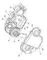
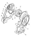
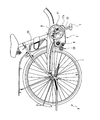
図1は本発明の実施の形態に係る電動自転車の右側面図、図2は同電動自転車のモータ駆動ユニットの概略的な平面断面図(駆動力伝達構造等をわかり易く表示するため、各回転軸中心を結んだ切断線で概略的に切断した状態を示す)、図3は同モータ駆動ユニットのユニットケースのみの平面断面図、図4、図5はそれぞれ同モータ駆動ユニット(モータ部を除く)の概略的な分解斜視図である。 FIG. 1 is a right side view of an electric bicycle according to an embodiment of the present invention, and FIG. 2 is a schematic plan sectional view of a motor drive unit of the electric bicycle. FIG. 3 is a plan sectional view of only the unit case of the motor drive unit, and FIGS. 4 and 5 respectively show the motor drive unit (excluding the motor portion). FIG.
図2などに示すように、この電動自転車のモータ駆動ユニット30でも、モータ駆動ユニット30の外殻部分などをなすユニットケース31が、モータ部12の外殻をなすモータケース部32と、モータ部12以外の外殻部分、すなわち、トルク検出部11、制御回路部17および減速機構部13の、左側の側壁部(一方の内壁部)をなす第1ケース部としての左ケース部33と、右側の側壁部(他方の内壁部)をなす第2ケース部としての右ケース部34との、3つのケース部から構成され、これらのケース部32,33,34が複数のボルト等を用いて組み合わせられてユニットケース31として一体化されている。また、左ケース部33においてモータ部12に臨むように一体形成された部分である隔壁部33aにより、モータ部12と、減速機構部13および制御回路部17とが左右に仕切られている。なお、この実施の形態では、減速機構部13とモータ部12とにより駆動部が構成されている。
As shown in FIG. 2 and the like, also in the
また、左ケース部33の一部(電動モータ4の回転軸4aを回転自在に支持する右側のモータ軸受18の近傍箇所)から電動自転車の右側に向けて、かつ側面視して略円弧状に延びるように仕切壁部33bが一体形成されているが、この仕切壁部33bは、ユニットケース31の右側壁部をなす右ケース部34に達しないで、右ケース部34に対して隙間を有する位置までしか延設されていない。一方、このモータ駆動ユニット30では、減速機構部13の前側寄り部分を覆う駆動部カバー40が設けられており、この駆動部カバー40は、左ケース部33の仕切壁部33bの端縁にその外周部が重なる状態で取り付けられている。この実施の形態においては、左ケース部33の仕切壁部33bの端縁に設けられた凸部33c(図4参照)と、駆動部カバー40に形成された凹部40a(図5参照)とが嵌合する状態で、互いの端縁同士が重ねられている。駆動部カバー40は側面視して略円弧形状とされ、後縁部は駆動スプロケット6の出力軸6aの外周部近傍箇所まで延設されている。なお、33fはトルク検出部11の左側部分を覆う筒状部である。
Further, from a part of the left case portion 33 (a portion in the vicinity of the right motor bearing 18 that rotatably supports the
また、右ケース部34には、トルク検出部11の右側部分を覆う筒状部34aと、この筒状部34aの後方箇所から後方に延びて制御回路部17を略箱形状に収容する回路覆い部34bと、減速機構部13の右側部分を覆う減速機構覆い部34cとが一体形成され、減速機構覆い部34cには、駆動スプロケット6の出力軸6aの右側の出力軸受36を受ける軸支部34dも一体形成されているが、さらに、軸支部34dと減速機構覆い部34cとの接続箇所近傍から左側に延びる補助仕切壁部34fも一体形成され、この補助仕切壁部34fの先端が駆動部カバー40に突き合わされている。
Further, the
そして特に、このモータ駆動ユニット30では、右ケース部34の回路覆い部34bと左ケース部33の隔壁部33aとの間だけでなく、右ケース部34の回路覆い部34bと駆動部カバー40との間も、制御回路16が収容される制御回路部17として用いられている。したがって、制御回路部17の制御回路16と減速機構部13は、側面視して(クランク軸心方向に沿う方向に見て)重なるように配置されている。
In particular, in the
この構成により、モータ駆動ユニット30における減速機構部13の制御回路部17寄り部分が、左ケース部33の仕切壁部33bおよび駆動部カバー40により覆われるので、減速機構部13からグリスや粉塵などが制御回路16の配設空間である制御回路部17に侵入することを防止できる。
With this configuration, the portion near the
また、上記構成により、駆動部カバー40とユニットケース31の他方の内壁部としての右ケース部34の回路覆い部34bとの間の空間にも制御回路部17の制御回路16を配置すること、すなわち、制御回路部17の制御回路16と減速機構部13とを、側面視して重なるように配置することが可能となるので、重なるように配置した距離分だけモータ駆動ユニット30を前後方向に対して小型化することができ、モータ駆動ユニット30の配置の自由度を高めることができる。また、モータ駆動ユニット30を小型化することで、路面の障害物などに当接する確率も小さくなり、当接時の衝撃による制御回路16の損傷なども低減できて信頼性が向上する。
Further, with the above configuration, the
また、予め駆動部カバー40を左ケース部33の仕切壁部33bに装着して減速機構部13の制御回路部寄り部分を覆った後に、制御回路部17の制御回路16の配線コード16aを配線することで、左ケース部33に右ケース部34を組み付ける時に配線コード16aを挟み込んで損傷させることがなくなり、これによっても信頼性が向上する。
In addition, after the
なお、上記の実施の形態では、駆動部カバー40の外周部が左ケース部33の仕切壁部33bの先端部に付き合わせられるように配置した場合を述べたが、これに限るものではなく、図6に示すように、駆動部カバー40の外周部と、左ケース部33の仕切壁部33bの先端部とが減速歯車5aの半径方向に沿う方向に対して重なるような形状に駆動部カバー40の外周端部40cや仕切壁部33bの先端部を形成して、いわゆるラビリンス構造を採用してもよく、これによれば、減速機構部13からグリスや粉塵などが制御回路16の配設空間である制御回路部17に侵入することを一層確実に防止できる。
In the above-described embodiment, the case where the outer peripheral portion of the
また、上記実施の形態では、右ケース部34に補助仕切壁部34fが一体形成されている場合を述べたが、この補助仕切壁部34fを設けずに、駆動部カバー40の後縁部を、出力軸受36の外周部前側に突き合わして覆う構成としてもよい。
In the above embodiment, the case where the auxiliary
また、上記実施の形態では、減速機構部13からグリスや粉塵などが制御回路部17に侵入することを防止した構造としたが、電動モータとして小型のものを用いて、前記減速機構部内に電動モータも収容されている構造とした場合や、減速機構部13がなくて電動モータの出力軸に駆動スプロケットを直接取り付けた構造とした場合でも、同様な構成を採用することは可能である。
In the above embodiment, grease or dust is prevented from entering the
本発明の電動自転車ならびにモータ駆動ユニットは、ペダルからの人の踏力による人力駆動力に、電動モータにより発生するモータ駆動ユニットの補助駆動力を加えることができるように構成した電動自転車に特に適しているが、その他の物品に用いられるモータ駆動ユニットの構造としても利用可能である。 The electric bicycle and the motor drive unit of the present invention are particularly suitable for an electric bicycle configured to be able to add the auxiliary drive force of the motor drive unit generated by the electric motor to the human drive force generated by the pedaling force of the person from the pedal. However, it can also be used as a structure of a motor drive unit used for other articles.
4 電動モータ
6 駆動スプロケット
11 トルク検出部
12 モータ部
13 減速機構部
17 制御回路部
30 モータ駆動ユニット
31 ユニットケース
32 モータケース部
33 左ケース部(一方の側壁部)
33a 隔壁部
34 右ケース部(他方の側壁部)
33b 仕切壁部
40 駆動部カバー
4
Claims (2)
前記ユニットケースを、電動モータの外殻をなすモータケース部と、駆動部および制御回路部の一方の側壁部をなす第1ケース部と、駆動部および制御回路部の他方の側壁部をなす第2ケース部とから構成し、
前記第1ケース部および第2ケース部のそれぞれに、制御回路部を覆う回路覆い部を形成し、
前記第1ケース部に、前記駆動部と制御回路部との間を仕切るように第1ケース部の内壁部から前記第2ケース部の内壁部に向かって延びる仕切壁部を、前記第2ケース部の内壁部に達しないで隙間を有する状態に形成し、
前記第1ケース部の仕切壁部の端縁にその外周部が重なりかつその内周部が減速機に設けられた出力軸側に延びる状態で駆動部カバーを取り付け、この駆動部カバーにより駆動部の制御回路部寄り部分を覆い、
前記第2ケース部の回路覆い部を前記減速機の出力軸近傍まで延ばすとともに、前記減速機の出力軸近傍箇所で減速機側に屈曲させて前記駆動部カバーに当接する補助仕切壁部を形成することで、制御回路部の空間を、電動モータの出力軸よりもクランク軸配設部側から離れた箇所にある前記減速機の出力軸近傍まで拡張させた電動自転車。 A motor driving unit for generating the auxiliary driving force applied to the human power, the motor drive unit, a crank shaft disposing portion crankshaft is supported freely inserted rotated, the speed reducer and the electric motor is disposed and have been driving unit, and a control circuit unit disposed between the control circuit is arranged Rutotomoni crankshaft arrangement portion and the reducer, these crankshaft arrangement portion, a drive and control circuit unit An electric bicycle provided with a unit case for housing,
The unit case includes a motor case portion that forms an outer shell of the electric motor, a first case portion that forms one side wall portion of the drive portion and the control circuit portion, and a second case portion that forms the other side wall portion of the drive portion and the control circuit portion. Consists of two case parts,
In each of the first case portion and the second case portion, a circuit cover portion that covers the control circuit portion is formed,
Wherein the first case portion, a partition wall portion extending from the inner wall portion of the first case portion to the inner wall of the second case portion to partition between the driver and the control circuit unit, the second case not reach the inner wall parts are formed in a state where a gap,
The drive unit cover attached in a state that the outer peripheral portion to the edge of the partition wall portion that overlap with Li Kui inner peripheral portion thereof extending output shaft provided on the reduction gear of the first case portion, by the drive unit cover not covering the control circuit part closer to the part of the drive unit,
The circuit cover portion of the second case portion extends to the vicinity of the output shaft of the speed reducer, and an auxiliary partition wall portion that is bent toward the speed reducer side near the output shaft of the speed reducer and abuts on the drive portion cover is formed. By doing so, the electric bicycle in which the space of the control circuit section is expanded to the vicinity of the output shaft of the speed reducer located farther from the crankshaft arrangement portion side than the output shaft of the electric motor .
Priority Applications (1)
| Application Number | Priority Date | Filing Date | Title |
|---|---|---|---|
| JP2005178663A JP4726552B2 (en) | 2005-06-20 | 2005-06-20 | Electric bicycle |
Applications Claiming Priority (1)
| Application Number | Priority Date | Filing Date | Title |
|---|---|---|---|
| JP2005178663A JP4726552B2 (en) | 2005-06-20 | 2005-06-20 | Electric bicycle |
Publications (2)
| Publication Number | Publication Date |
|---|---|
| JP2006353045A JP2006353045A (en) | 2006-12-28 |
| JP4726552B2 true JP4726552B2 (en) | 2011-07-20 |
Family
ID=37648275
Family Applications (1)
| Application Number | Title | Priority Date | Filing Date |
|---|---|---|---|
| JP2005178663A Expired - Lifetime JP4726552B2 (en) | 2005-06-20 | 2005-06-20 | Electric bicycle |
Country Status (1)
| Country | Link |
|---|---|
| JP (1) | JP4726552B2 (en) |
Families Citing this family (7)
| Publication number | Priority date | Publication date | Assignee | Title |
|---|---|---|---|---|
| JP5393354B2 (en) * | 2009-08-31 | 2014-01-22 | 本田技研工業株式会社 | Electric motorcycle |
| JP6081810B2 (en) * | 2013-02-13 | 2017-02-15 | アスモ株式会社 | Motor actuator |
| JP6456060B2 (en) * | 2014-07-02 | 2019-01-23 | 日本電産サンキョー株式会社 | Geared motor and automatic switching unit |
| CN107672732A (en) * | 2017-11-08 | 2018-02-09 | 广州市快易达工贸有限公司 | A kind of built-in motor using dynamic pickup electrical combination |
| CN110715027B (en) * | 2018-07-13 | 2023-03-14 | 富田电机股份有限公司 | Power assembly of electric locomotive |
| ES2881082T3 (en) * | 2018-08-09 | 2021-11-26 | Fukuta Electric & Machinery Co Ltd | Power set for electric scooter |
| JP2023098435A (en) * | 2021-12-28 | 2023-07-10 | ニデック株式会社 | drive unit, electric vehicle |
Family Cites Families (5)
| Publication number | Priority date | Publication date | Assignee | Title |
|---|---|---|---|---|
| JP2000335476A (en) * | 1999-05-31 | 2000-12-05 | Matsushita Electric Ind Co Ltd | Drive unit for bicycle with auxiliary power and bicycle with auxiliary power |
| JP2001206275A (en) * | 2000-01-28 | 2001-07-31 | Matsushita Electric Ind Co Ltd | Electric assisted bicycle |
| JP2001213382A (en) * | 2000-01-31 | 2001-08-07 | Matsushita Electric Ind Co Ltd | Bicycle with auxiliary power |
| JP4079642B2 (en) * | 2002-01-23 | 2008-04-23 | 松下電器産業株式会社 | Electric bicycle motor unit |
| JP4311722B2 (en) * | 2003-09-12 | 2009-08-12 | 株式会社ミツバ | Electric motor with reduction mechanism |
-
2005
- 2005-06-20 JP JP2005178663A patent/JP4726552B2/en not_active Expired - Lifetime
Also Published As
| Publication number | Publication date |
|---|---|
| JP2006353045A (en) | 2006-12-28 |
Similar Documents
| Publication | Publication Date | Title |
|---|---|---|
| JP6936186B2 (en) | Drive unit for human-powered vehicles | |
| JP5634645B1 (en) | Electric assist bicycle | |
| JP6926167B2 (en) | Drive unit and electric auxiliary bicycle | |
| JP4726552B2 (en) | Electric bicycle | |
| WO2020100901A1 (en) | Electric bicycle motive force transmission unit and electric bicycle | |
| JPWO2014009995A1 (en) | Electric assist bicycle | |
| EP3441296B1 (en) | Drive unit and electrically assisted bicycle | |
| US12325489B2 (en) | Power module of electric assisted bicycle | |
| JP2007118920A (en) | Electric power steering apparatus for automobile | |
| JPWO2019103022A1 (en) | Electric assisted bicycle drive unit and electrically assisted bicycle | |
| TW201922567A (en) | Bicycle component | |
| TW201922571A (en) | Bicycle drive unit | |
| JP3617728B2 (en) | Electric auxiliary vehicle | |
| JP2022121335A (en) | Drives and electric vehicles | |
| JP2019142351A (en) | Power-assisted bicycle and driving unit | |
| JP2024149551A (en) | Drive unit for human-powered vehicles | |
| TW201922570A (en) | Bicycle drive unit | |
| JP2008189136A (en) | Electric auxiliary device for power assisted bicycle, and power assisted bicycle | |
| JPWO2020175524A1 (en) | Motor unit and electric bicycle | |
| US11292553B2 (en) | Bicycle with a power assist transmission device | |
| JP2020079016A (en) | Power transmission unit for electric bicycle and electric bicycle | |
| JP2007176221A (en) | Motor unit and electric bicycle using the same | |
| JP3182506B2 (en) | Power unit for electric bicycle | |
| JP2023098435A (en) | drive unit, electric vehicle | |
| JP2022121334A (en) | Drives and electric vehicles |
Legal Events
| Date | Code | Title | Description |
|---|---|---|---|
| RD04 | Notification of resignation of power of attorney |
Free format text: JAPANESE INTERMEDIATE CODE: A7424 Effective date: 20080430 |
|
| A621 | Written request for application examination |
Free format text: JAPANESE INTERMEDIATE CODE: A621 Effective date: 20080620 |
|
| A977 | Report on retrieval |
Free format text: JAPANESE INTERMEDIATE CODE: A971007 Effective date: 20101215 |
|
| A131 | Notification of reasons for refusal |
Free format text: JAPANESE INTERMEDIATE CODE: A131 Effective date: 20110105 |
|
| A521 | Request for written amendment filed |
Free format text: JAPANESE INTERMEDIATE CODE: A523 Effective date: 20110215 |
|
| TRDD | Decision of grant or rejection written | ||
| A01 | Written decision to grant a patent or to grant a registration (utility model) |
Free format text: JAPANESE INTERMEDIATE CODE: A01 Effective date: 20110315 |
|
| A61 | First payment of annual fees (during grant procedure) |
Free format text: JAPANESE INTERMEDIATE CODE: A61 Effective date: 20110412 |
|
| R151 | Written notification of patent or utility model registration |
Ref document number: 4726552 Country of ref document: JP Free format text: JAPANESE INTERMEDIATE CODE: R151 |
|
| FPAY | Renewal fee payment (event date is renewal date of database) |
Free format text: PAYMENT UNTIL: 20140422 Year of fee payment: 3 |
|
| EXPY | Cancellation because of completion of term |